

Page 1
SERVICE MANUAL LCD COLOUR TELEVISION
LC-20C2E
SERVICE MANUAL
S81Y6LC-20C2E
LCD COLOUR TELEVISION
MODEL LC-20C2E
MODEL
In the interests of user-safety (Required by safety regulations in some countries) the set should be restored to its
original condition and only parts identical to those specified
be used.
LC-20C2E
CONTENTS
Page
» IMPORTANT SERVICE SAFETY PRECAUTION ................................................................................ 2
» ELECTRICAL SPECIFICATIONS......................................................................................................... 3
» OPERATION MANUAL......................................................................................................................... 4
» OUTLINE DIMENSION FIGURE .......................................................................................................... 5
» DISASSEMBLY OF THE SET .............................................................................................................. 6
» ADJUSTING PROCEDURE OF EACH SECTION ............................................................................... 9
» TROUBLE SHOOTING TABLE ..........................................................................................................12
» CHASSIS LAYOUT............................................................................................................................. 17
» BLOCK DIAGRAMS ........................................................................................................................... 20
» DESCRIPTION OF SCHEMATIC DIAGRAM ..................................................................................... 23
» OVERALL SCHEMATIC DIAGRAM ................................................................................................... 24
» SCHEMATIC DIAGRAMS................................................................................................................... 26
» PRINTED WIRING BOARD ASSEMBLIES........................................................................................ 46
» PARTS LIST
Ë
ELECTRICAL PARTS .................................................................................................................... 50
INVERTER A UNIT................................................................................................................ ......... 50
INVERTER B UNIT ........................................................................................................................ 50
MAIN UNIT ..................................................................................................................................... 50
VIDEO UNIT................................................................................................................................... 54
SWITCH UNIT................................................................................................................................ 55
S-OUT UNIT................................................................................................................................... 55
Ë
CABINET PARTS LIST .................................................................................................................. 56
Ë
SUPPLIED ACCESSORIES PARTS.............................................................................................. 56
Ë
PACKING PARTS........................................................................................................................... 56
Ë
CABINET AND MECHANICAL PARTS.......................................................................................... 57
» PACKING OF THE SET...................................................................................................................... 58
SHARP CORPORATION
1
Page 2
LC-20C2E
5
5
Ë
Service work should be perfomed only by qualified service technicians who are thoroughly
familiar with all safety checks and the servicing guidelines which follow:
IMPORTANT SERVICE SAFETY PRECAUTION
WARNING
1. For continued safety, no modification of any circuit
should be attempted.
2. Disconnect AC power before servicing.
CAUTION
FOR CONTINUED PROTECTION
AGAINST A RISK OF FIRE REPLACE
ONLY WITH SAME TYPE FUSE.
F1 (2A, 250V), F2 (1.6A, 250V), F4 (315mA, 250V)
FUSE.
BEFORE RETURNING THE RECEIVER
(Fire & Shock Hazard)
Before returning the receiver to the user, perform the
following safety checks:
1. Inspect all lead dress to make certain that leads are not
pinched, and check that hardware is not lodged between
the chassis and other metal parts in the receiver.
2. Inspect all protective devices such as non-metallic
control knobs, insulation materials, cabinet backs,
adjustment and compartment covers or shields, isolation
resistor-capacitor networks, mechanical insulators, etc.
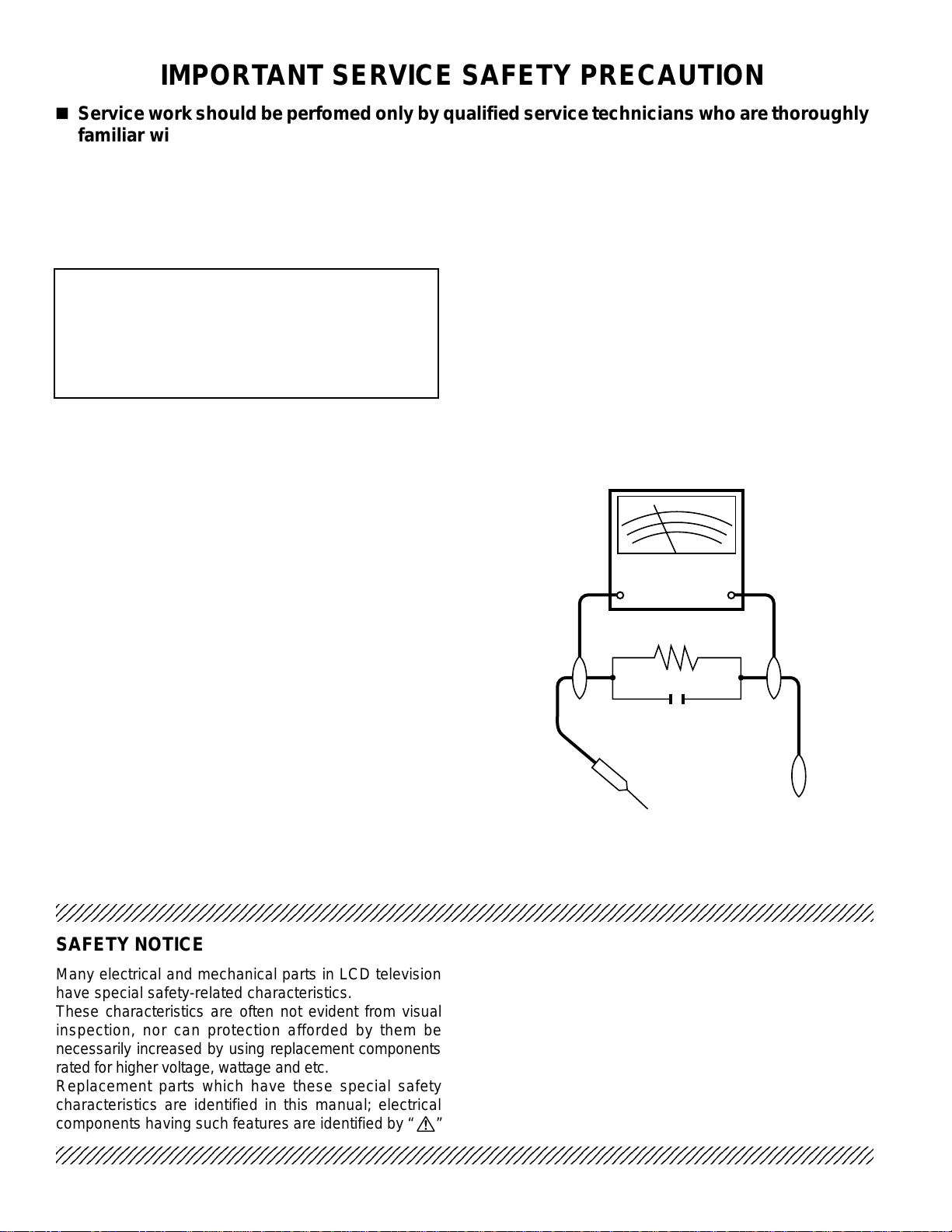
3. T o be sure that no shock hazard exists, check for leakage
current in the following manner.
• Plug the AC cord directly into a 110~240 volt AC outlet,
and connect the DC power cable into the receiver's DC
jack. (Do not use an isolation transformer for this test).
• Using two clip leads, connect a 50k ohm, 10 watt resistor
paralleled by a 0.15µF capacitor in series with all
exposed metal cabinet parts and a known earth ground,
such as electrical conduit or electrical ground connected
to earth ground.
• Use an AC voltmeter having with 5000 ohm per volt, or
higher, sensitivity or measure the AC voltage drop across
the resisor.
• Connect the resistor connection to all exposed metal
parts having a return to the chassis (antenna, metal
cabinet, screw heads, knobs and control shafts,
escutcheon and etc.) and measure the AC voltage drop
across the resistor.
All checks must be repeated with the AC cord plug
connection reversed. (If necessary, a nonpolarized
adaptor plug must be used only for the purpose of
completing these checks.)
Any reading of 0.75V peak (this corresponds to 0.5
milliamp. peak AC.) or more is excessive and indicates
a potential shock hazard which must be corrected before
returning the monitor to the owner.
DVM
AC SCALE
50k ohms.
10W
0.15 µF
TEST PROBE
TO EXPOSED
METAL PARTS
CONNECT TO
KNOWN EARTH
GROUND
234567890123456789012345678901212345678901234567890123456789012123456789012345678901234567890121234
SAFETY NOTICE
Many electrical and mechanical parts in LCD television
have special safety-related characteristics.
These characteristics are often not evident from visual
inspection, nor can protection afforded by them be
necessarily increased by using replacement components
rated for higher voltage, wattage and etc.
Replacement parts which have these special safety
characteristics are identified in this manual; electrical
and shaded areas in the
Schematic Diagrams
For continued protection, replacement parts must be
identical to those used in the original circuit.
The use of a substitute replacement parts which do not
have the same safety characteristics as the factory
recommended replacement parts shown in this service
manual, may create shock, fire or other hazards.
components having such features are identified by “ å”
234567890123456789012345678901212345678901234567890123456789012123456789012345678901234567890121234
2
Replacement Parts Lists
.
and
Page 3

ELECTRICAL SPECIFICATIONS
Items .............................................................20" LCD COLOUR TV, Model: LC-20C2E
LCD panel .................................................................................. 19.7" BLACK TFT LCD
Number of pixels........................................................................................ 921,600 dots
Video colour system ........................................................................PAL/SECAM/NTSC
TV FUNCTION
TV Standard (CCIR) .......................................................................BG/L/DK, I, M, N
TV Tuning System ..................................................................... Auto preset 197 ch.
STEREO/BILINGUAL ............................................................................NICAM, IGR
AUTO PRESET ................................................................................................... Yes
CATV.....................................................................................................~Hyper Band
Brightness....................................................................................................... 430 cd/m
Lamp life ....................................................................................................60,000 hours
Viewing angles....................................................................................... H: 160° V: 160°
Audio amplifier ................................................................................................. 2.5W × 2
Speakers....................................................................................................5 cm φ 2 pcs.
Terminals
A V-IN1................................................................................................................ RGB
AV-IN2.............................................................................. S-VIDEO, VIDEO, AUDIO
OUT ................................................................................................................AUDIO
ANTENNA............................................................................................................DIN
HEADPHONES........................................................................3.5 mm φ jack (Front)
OSD language ...................... English/German/French/Spanish/Italian/Swedish/Dutch/
Power requirement .................................................. DC 13V, AC 110 - 240 V, 50/60 Hz
Power consumption ........................................................... 42W (Connected to DC13V)
Dimensions .............................................476.6mm (W) × 556.4mm (H) × 229.4mm (D)
Weight................................................................... 8.0 kg, incl. stand, excl. accessories
Accessories ........................................ R/C, Batteries, AC adaptor, Power supply cord,
Operation manual, Cable clamp
LC-20C2E
2
Specifications are subject to change without prior notice.
3
Page 4
LC-20C2E
OPERATION MANUAL
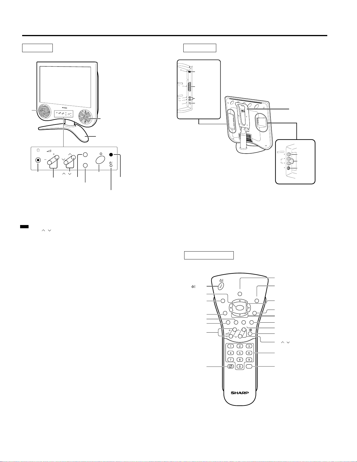
Controls Terminals
Front view
To change the vertical angle of the LCD
TV set, tilt the screen up to 5 degrees
forward or 10 degrees backward. The TV
set can also be rotated 40 degrees
horizontally. Please adjust the angle so
that the TV set can be watched most
comfortably.
Speaker
(Left)
Control panel
Headphone
CH
TV/VIDEO
MENU
CH ( )/( )
Volume (+)/(–)
TV/VIDEO
MENU
A green indicator lights when the power is on and a red
indicator lights when in the standby mode (the indicator
Power/Standby indicator
will not light when the main power is off).
Speaker (Right)
Table stand
MAIN POWER
Remote sensor
window
AV-IN 1
RGB
AUDIO OUT
POW
INPUT
DC13V
L
R
ER
Antenna
AV-IN 1
(21-pin EuroSCART)
AUDIO OUT (L)
AUDIO OUT (R)
POWER INPUT
DC 13 V
Rear view
AV-IN 2
S-VIDEO
VIDEO
AUDIO
Carring handle
L
R
VIDEO
AUDIO (L)
AUDIO (R)
S-VIDEO
Note:
TV/VIDEO, CH(
the remote control. Fundamentally, this operation manual provides a description based on operation using the
remote control.
)/( ), and Volume (+)/(–) on the main unit have the same functions as the same buttons on
Remote control
(Power)
OK, Programme Table
INFO
Turns on the menu
information when
the menu is displayed.
GREEN, Sound Menu
RED, Picture Menu
TEXT
Volume (+)/(–)
Flashback
Returns to the
previous channel.
SOUND
INFO
iE
T
(
RED)(GREEN)(YELLOW)(CYAN
CH
END
OK
MENUTEXT
M
)
TV/VIDEO
SOUND
Switches the sound mode.
END, Status Display
Turns on the status display
when the menu is not
displayed.
Upward / Downward
Selection
MENU
Right / Left Selection
CYAN, Teletext Subtitle
YELLOW, Standard Value
Mute
CH ( )/( )
Channel Select
TV/VIDEO
4
Page 5
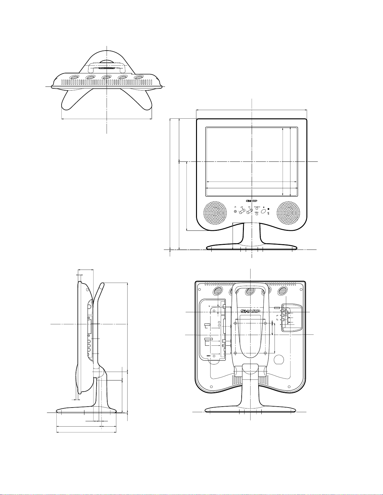
OUTLINE DIMENSION FIGURE
476.6
379
187
401.3
556.4
403.28
298.8
300.8
LC-20C2E
9
56.5
0.5
295.8
296.3
369.4
110
1
AV-IN 1
AUDIO OUT
POWER
INPUT
DC12V
18
100
RGB
L
R
2815 49 66.5
48
S-VIDEO
3.5
AV-IN 2
VIDEO
15
L
AUDIO
15
R
16
100
8
163.9
18.5
229.4
12.5
65.5
256.9
220.4
1
Units: mm
5
Page 6
LC-20C2E
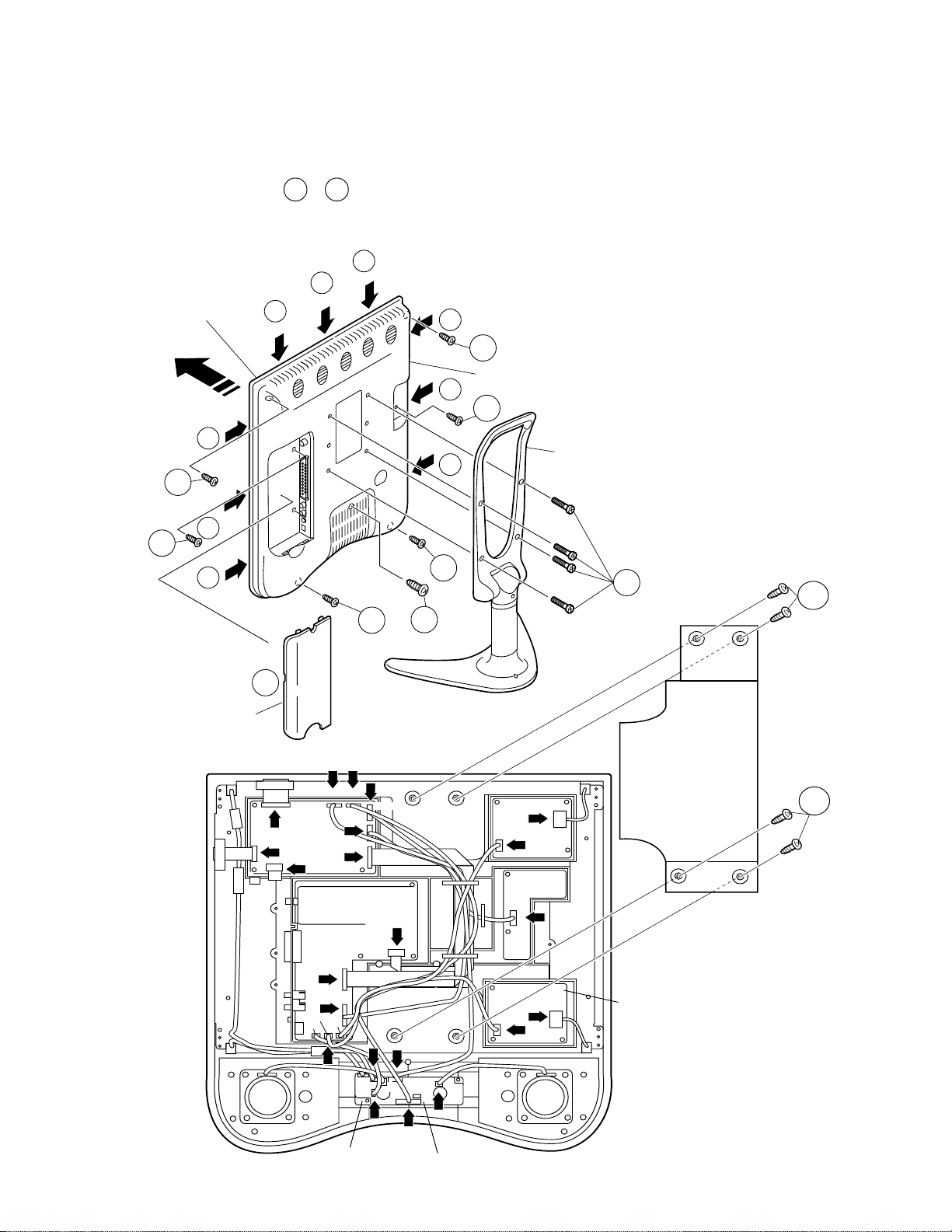
DISASSEMBLY OF THE SET
1. Remove 4 screws from the stand.
2. Detatch the terminal cover.
3. Remove 5 screws from the B cabinet.
4. Remove 3 screws.
5. A cabinet is opened in order of 5-1 ~ 5-9, and B cabinet is removed.
6. Remove 4 screws and detatch the stand fixing angle.
7. Disconnect the connectors from the PWBs.
5-4
5-5
Cabinet A
5-7
3
5-8
4
5-9
Terminal Cover
5-6
5-3
3
Cabinet B
5-2
4
Stand
5-1
3
1
6
3
3
2
7
7
SC1202
P2003 P3301
SC1201
(Main PWB)
7
P701
7
P903
SC901
(Tuner Unit)
SC902
7
P904
P702
P703
P3601
P3604
(SWITCH PWB)
SC802
P3602
P901
7
P305
P3302
P4004
7
(S-OUT PWB)
6
(Inverter A
PWB)
P6751P6755
7
(Video PWB)
P5001
7
P6551
7
P6555
P304
(Inverter B PWB)
6
Page 7
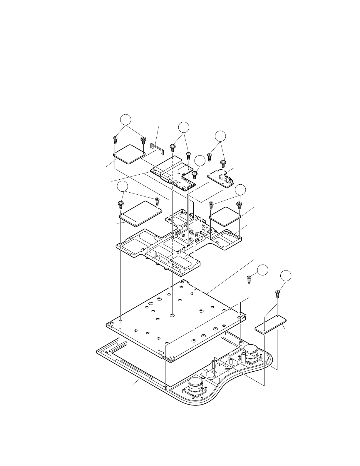
8. Remove 2 screws from the INVERTER A PWB.
9. Remove 4 screws from the TUNER PWB.
10.Remove 2 screws from the VIDEO PWB.
11.Remove 3 screws from the MAIN PWB.
12.Remove 2 screws from the INVERTER B PWB.
13.Remove 2 screws form the LCD panel.
14.Remove 2 screws from the S-OUT PWB.
LC-20C2E
Inverter A PWB
Tuner Unit
Main PWB
11
8
21pin Terminal
Fixing Angle
9
10
9
Video PWB
12
Inverter B PWB
Chassis Frame
LCD Panel
13
14
A Cabinet
Switch PWB
7
Page 8
LC-20C2E
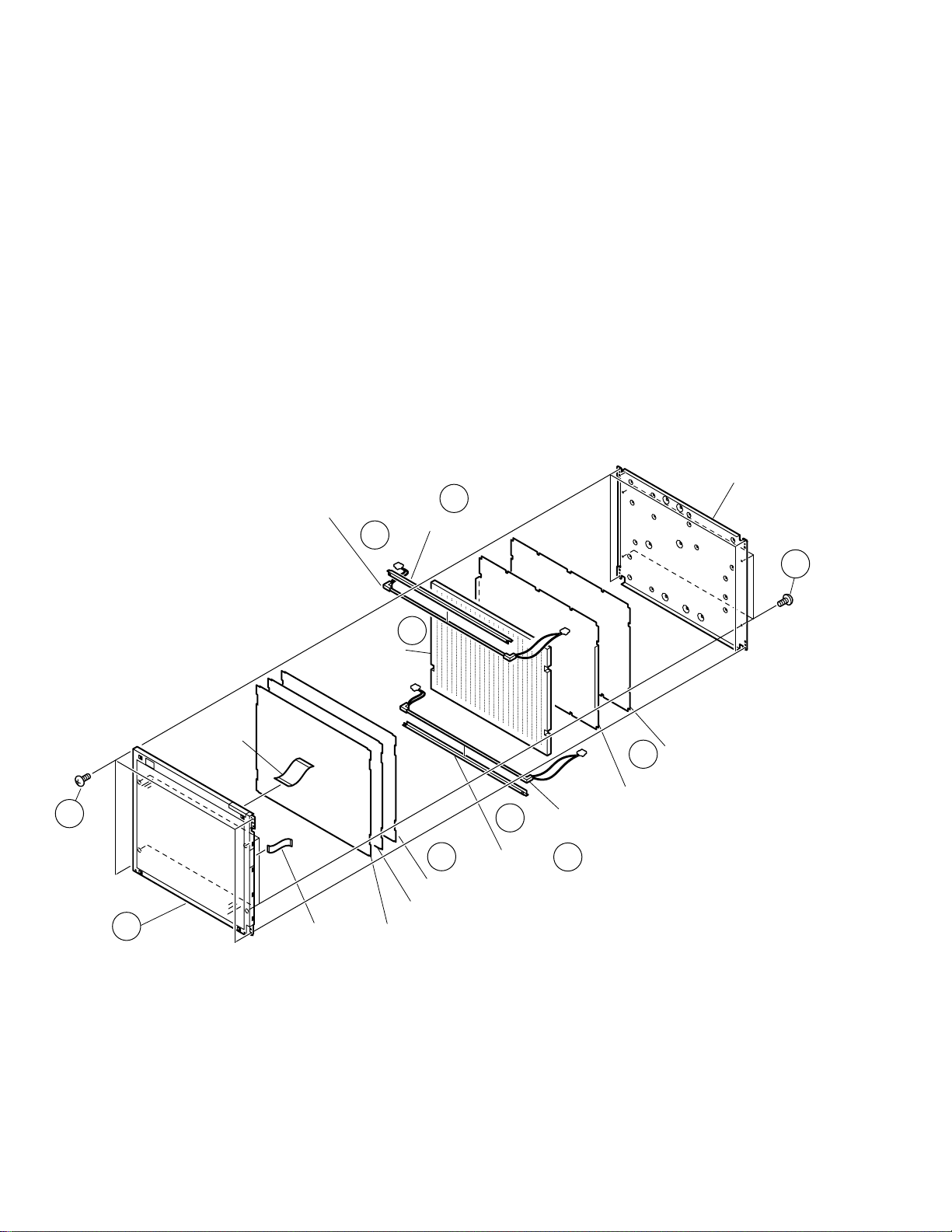
• Precautions in handling the LCD panels.
1. Work in a clean room. (with humidities below 50%)
2. Be sure to wear an anti-static armband.
3. Handle the panels on an electroconductive mat.
4. Be careful not to fall, shake and shock the panels.
5. Use an ionizer. (within 30cm)
15.Remove 8 screws from the LCD unit and detach the shielding plate.
16.Remove 2 reflevction sheets.
17.Remove the fluorescent lamp.
18.Remove the light guide.
19.Remove the spacer.
20.Remove the diffusion sheet, prizm sheet and D-BEFE.
21.Remove the LCD Panel.
15
21
LCD Panel
Source-FFC
Fluorescent Lamp
17
Light Guide
GATE-FFC
Spacer
18
Prizm Sheet
D-BEFE
19
17
20
Diffusion Sheet
Fluorescent Lamp
Spacer
19
Shielding Plate
Reflection Sheet 2
16
Reflection Sheet 1
15
8
Page 9
LC-20C2E
ADJUSTING PROCEDURE OF EACH SECTION
[1] Entering the MAIN side adjustment process mode
There are three methods below.
1) Press the “Adjustment process key” on the remote control after turning on the power.
2) Pressing both the MENU key and the TV/VIDEO key on the main body, turn on the power. Then, press the
volume DOWN key and the tuning DOWN key at the same time.
3) Turn on the power with falling either KEY4 (pin 81 of microcomputer) or KEY5 (pin 82 of microcomputer) to “L”.
[Note] For the method 3), the ROM is initialized at the same time. Therefore, 3) must be executed if IC2004 or
IC2001 is changed. For 1) or 2), the main body only enters the MAIN side adjustment process.
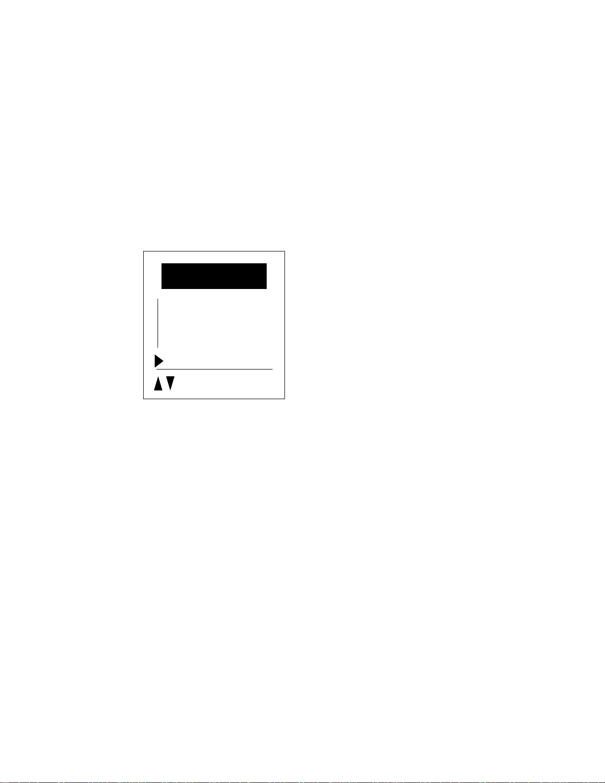
[2] Entering the TUNER side adjustment process mode
4) Entering the TUNER side adjustment process
MENU key on the main body → Cursor UP key (remote control) → Select the position shown in the figure below
and press the M key (remote control) within 1 second. → Enters the adjustment process.
Direct control at TV
Black level
Contrast
Colour
: select
M: Back
E: End
[3] Adjustment
MAIN side adjustment (Press the “M” key to move the cursor and press the volume UP/DOWN key to make an
adjustment.)
• Power supply voltage adjustment (+B 5V)
• Model setting
• Inch size setting
• COMMON BIAS adjustment of LCD module
• CUTOFF adjustment
TUNER side adjustment (Press the tuning UP/DOWN key to move the cursor and press the volume UP/DOWN key
to make an adjustment.)
• Horizontal size adjustment (LCD adjustments)
• Video adjustment (other adjustments)
Y delay
Subcontrast
Subcolour
Subbrightness
Tint offset
AGC gain start
The TUNER side adjustment is possible. However, it is recommended to replace EAROM (I2).
9
Page 10
LC-20C2E
3-1. +B adjustment
PAL/PAL60 SECAM NTSC
y delay 7 6
RF
AV1 tint offset 1 1 1
AV2 sub contrast 0 2 0
AVS
AGC gain start 23
Page 9 of MAIN side adjustment process +B-ADJ
Adjust the voltage of the pin 13 of P2002 to 5.0V±0.05V.
tint offset 0 0
sub contrast 2 2
sub colour 25 25
y delay 7 5 4
sub colour 30 30 20
y delay 7 5 1
tint offset 1 1 1
sub contrast 0 0 0
sub colour 30 30 30
3-2. Model setting
Page 9 of MAIN side adjustment process MODEL
Set to C2E.
3-3. Inch size setting
Page 9 of MAIN side adjustment process INCH SIZE
Set to 20.
3-4. COMMON BIAS adjustment of LCD module
Page 9 of MAIN side adjustment process COM BIAS
Input the picture of gray scale and adjust it so as to obtain the best contrast.
3-5. CUTOFF adjustment
Page 9 of MAIN side adjustment process R CUTOFF, B CUTOFF
Adjust it so as to obtain the optimal colour balance.
10
Page 11
[4] Lamp error detection
4-1. Functional description
This LCD colour television has a function (lamp error detection) to be turned OFF automatically for safety
when the lamp or lamp circuit is abnormal.
If the lamp or lamp circuit is abnormal, or some other errors happen, and the lamp error detection is
executed, the followings occur.
1 The main unit of television is turned OFF 5 seconds after it is turned ON. (The power LED on the front side
of TV turns from green to red.)
2 If the situation 1 happens 5 times sequentially , television can not be turned ON. (The power LED remains
red.)
4-2. Countermeasures
4-2-1. Check when turning OFF the lamp error detection
When television is turned OFF by the lamp error detection mentioned above, it enters the adjustment
process with the power LED red. Entering the adjustment process turns OFF the error detection and
turns ON TV.
This enables the operation check to detect errors in the lamp or lamp circuit.
Check whether "ERROR NO RESET" on line 7, page 1 of the adjustment process is 1 or more. If it is 1
or more, it indicates the lamp error detection was executed.
4-2-2. Resetting of the lamp error count
After confirming that the lamp or lamp circuit is normal, reset the lamp error count. Select "ERROR NO
RESET" on line 5, page 1 of the adjustment process and set the number to 0 using the volume button.
LC-20C2E
Page 1 of the adjustment process
1
+ B – A D J 160
M O D E L C2E
I NCH I S I ZE 20
N T S C P W M F R Q 0C0
ERROR NORESET 5
P M U T E OFF
Reset 0
C 2 E V E R 1 . 0 0
Afterwards, perform the operation check to confirm that the lamp error detection does not function.
11
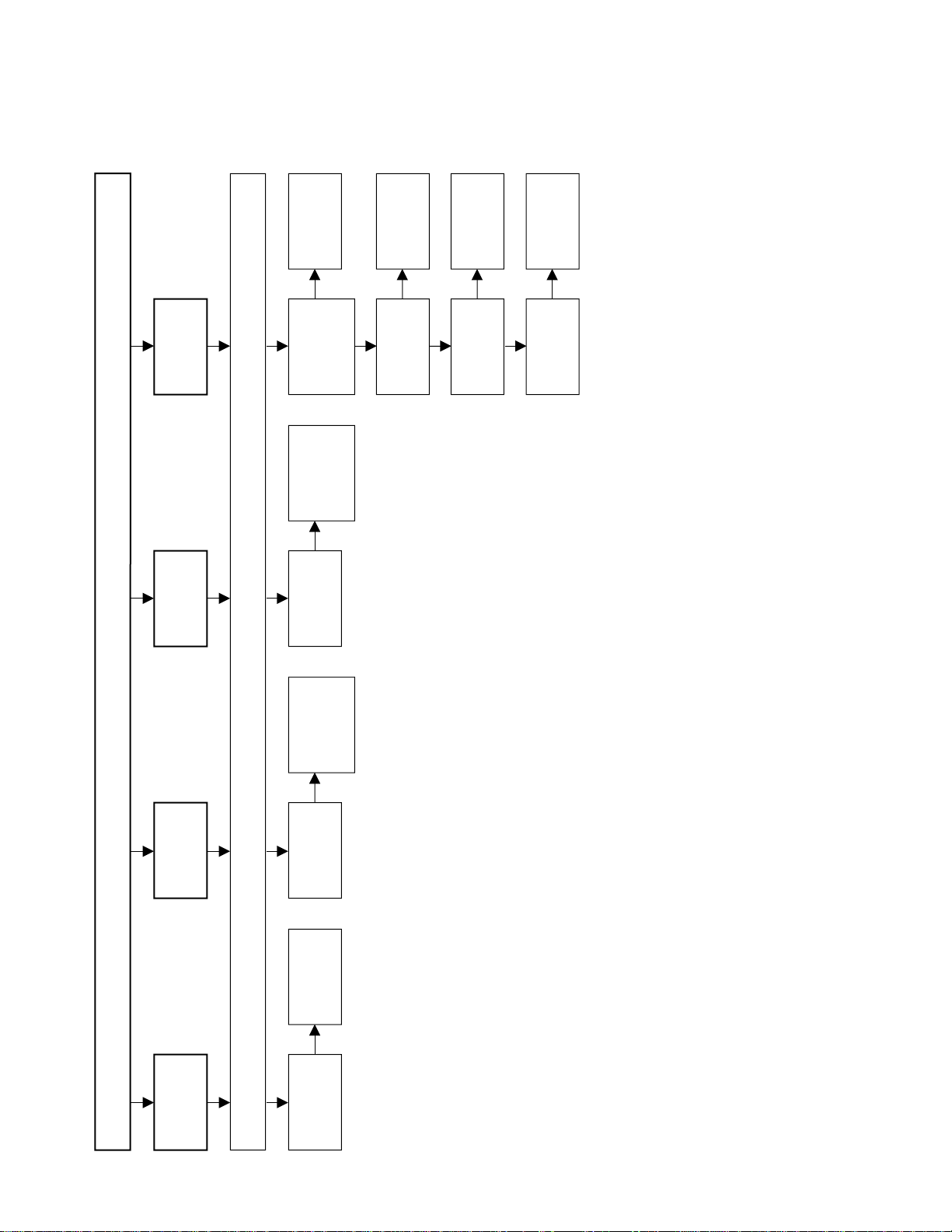
Page 12
LC-20C2E
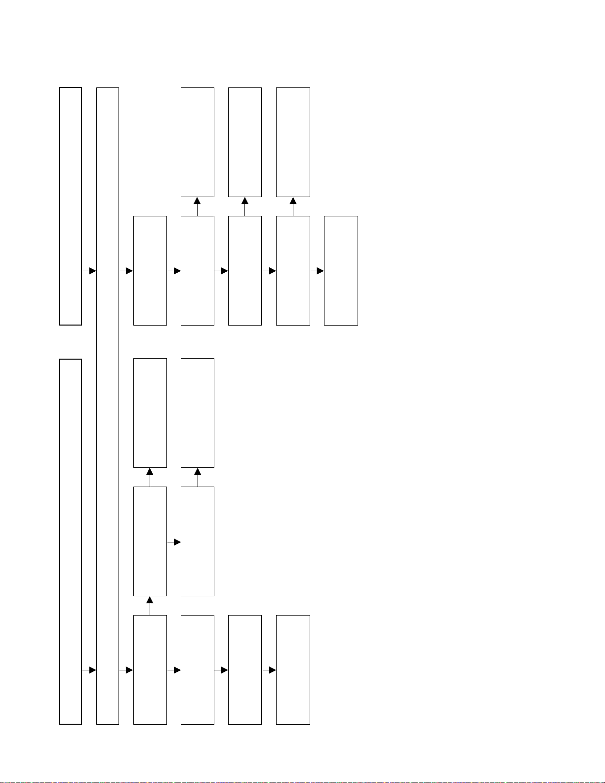
No picture, No sound
Check all the settings microprocessor's adjust process menu.
Do F2, F3, F4 and F5
function?
Are T701's secondary
outputs, +38V, +16V, +9V,
+5V and -8V normal?
Remove F2, F3, F4 and F5
and check the load side.
Is there short-circuiting?
Is there short-circuiting of
T701 primary side periphery,
Q751, Q753 and P901.
Replace F2, F3, F4 and F5.
Check P901 and
connection cable.
Is T701's primary oscillator
waveform normal?
Check T701's secondary
load.
Yes Yes
No
No No
No
Yes
Fluorecent lamp failure to light up
Does F1 function?
Is the pin 34 of IC1201 in
the "H" state?
Is the Q3603 short-circuiting?
Is there short-circuiting of
T5701 and T5702 primary
side periphery, Q751~Q753.
Yes
Yes
No
No
No
Yes
Replace the fluorecent lamp
with new one and check
again.
Yes
Check the OFL1 line, IC1201
and their peripheral parts.
Check Q3603 and their
peripheral parts.
Check T5701, T5702,
Q5701~Q5703 and
connection cable.
TROUBLE SHOOTING TABLE
12
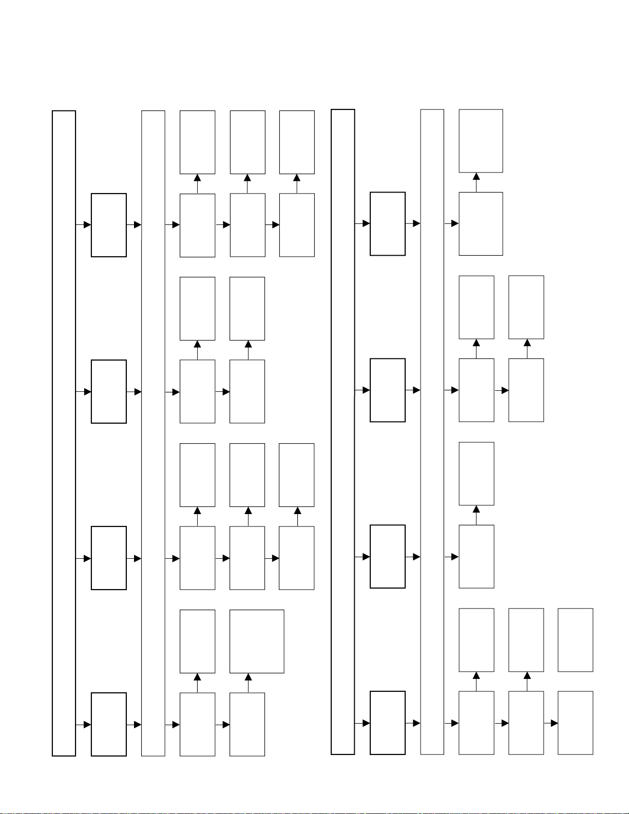
Page 13
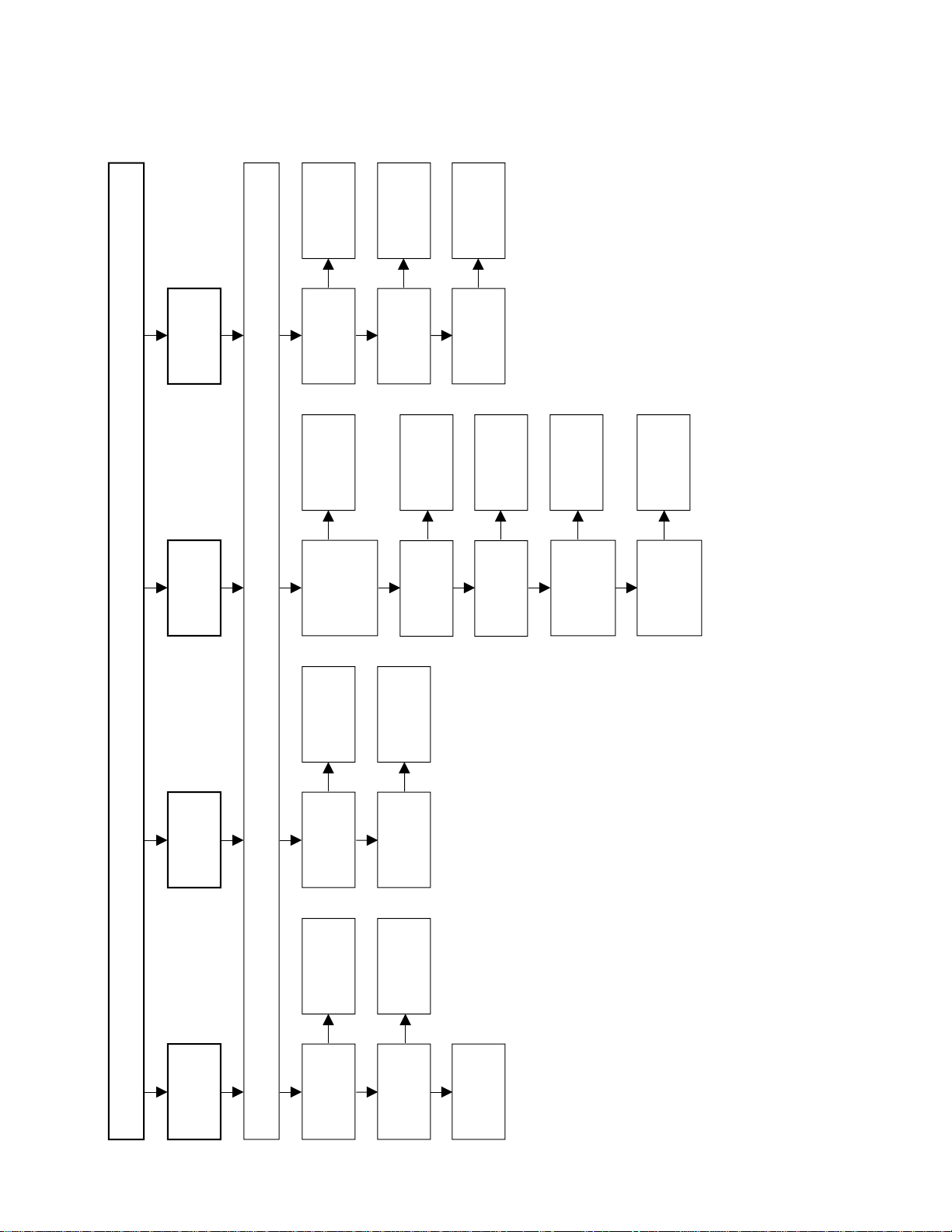
TROUBLE SHOOTING TABLE (Continued)
No picture
Check all the settings microprocessor's adjust process menu.
Is in/output of
IC801 normal?
Is in/output of
IC1201 normal?
Check IC801
and its
peripheral parts.
Check IC1201
and its
peripheral parts.
Check IC402
and its
peripheral parts.
Check IC801,
AV1 line and its
peripheral parts.
Check LCD
panel voltages
and waveform.
Yes
Yes
No
No
No picture
at all
Is in/output of
IC402 normal?
Is input at pin
73 of IC801
normal?
Yes
No
No
No TV and
VIDEO 1
output
Is voltages at
pin 3 of W7 and
pins 3, 4, 5 of
W14 tuner
normal?
Is output at pin
2 of W7 tuner
normal?
Check the
power line.
Check tuner
and its
peripheral parts.
Is input at pin
3 of IC402
normal?
Is the pins 2
and 4 of IC402
at "H" and "L"
state?
Yes
Yes
No
No
No
No
No
Yes
No TV output
Is the pins 65
and 66 of
IC2001 at "H"
and "L" state?
Yes
Check the its
line.
Check the its
line.
Check IC402
and its
peripheral parts.
Is input at pin
1 of IC402
normal?
Is the pins 2
and 4 of IC402
at "L" state?
Check the its
line.
Check the its
line.
Check IC402
and its
peripheral parts.
Is the pins 65
and 66 of IC2001
at "L" state?
Yes
Yes
No
No
No
No VIDEO 1
output
LC-20C2E
13
Page 14
LC-20C2E
No picture
Check all the settings microprocessor's adjust process menu.
Is input at pin
74 of IC801
normal?
Check the AV2
line and their
peripheral parts.
Check the W9,
SY-line, SC-line
and their
peripheral parts.
No
No VIDEO 2
output
Is input at pins
71 and 72 of
IC801 normal?
No
No S-VIDEO
output
Is input at pin
70 of IC801
normal?
Check the
V2VO line and
their
peripheral parts.
No
No line
output
Is input at pins
1, 2, 3, 56, 57
and 79 of IC801
normal?
Is output at pins
11, 13 and 16
of I4 normal?
Check IC801
and their
peripheral parts.
Check I13 and
their
peripheral parts.
Check I9 and
their
peripheral parts.
Check I4 and
their
peripheral parts.
Is output at pins
11, 13 and 16
of I13 normal?
Yes
Yes
No
No
No
No TELETEX
output
Is output at pins
44~49 of I9
normal?
Yes
No
TROUBLE SHOOTING TABLE (Continued)
14
Page 15
TROUBLE SHOOTING TABLE (Continued)
No picture
Check all the settings microprocessor's adjust process menu.
Is source GND
normal?
Is CSCOM
waveform
normal?
Check R1212
and their
peripheral parts.
Check IC1109,
Q1101, Q1102,
D1101, R1120,
R1130 and their
peripheral parts.
Check R1231
and their
peripheral parts.
Yes
No
No
Becomes
dark
No
Time passes,
becomes
dark
Is gate GND
normal?
Is gate clock
(GCK) normal?
Check R1223
and gate aray
peripheral parts.
Yes
No
Check D1201
and their
peripheral parts.
No
Is B-5.5V being
outputted?
Is VCC being
outputted?
Check T701's
secondary +5V
outputs line?
Yes
No
Is GSP
waveform
normal?
Check R1223
and their
peripheral parts.
Yes
No
Becomes
white.
Is 3.3V VHS
being
outputted?
Is source clock
normal?
Check +3.3V
outputs line of
IC752.
Check R1210,
R1211 and their
peripheral parts.
Check FB1203
and gate aray
peripheral parts.
Is output of LBR
and HG
normal?
Yes
Yes
No
No
No
Vertical line
output
No picture
Check all the settings microprocessor's adjust process menu.
Is output of
R0~R5
normal?
Is output of
G0~G5
normal?
Is output of
B0~B5
normal?
Check R1202,
R1203 and their
peripheral parts.
Check R1204,
R1205 and their
peripheral parts.
Check R1206,
R1207 and their
peripheral parts.
Check T701's
secondary +5V
outputs line.
Yes
Yes
No
No
Colour is
unusual
Is VLS 5V
being
outputted?
No
Picture
image is
gloomy
Is in/output of
SPIO and
SPOI normal?
Check R1209
and their
peripheral parts.
No
No picture
image
inversion
Is output V0,
V16, V32, V48
and V63
normal?
Check IC1106,
IC1107, IC1108
and their
peripheral parts.
No
Gradation
defect
Is output of U/D
normal?
Check Q1201
and their
peripheral parts.
Yes
No
LC-20C2E
15
Page 16

LC-20C2E
No sound
Check all the settins microprocessor's adjust process menu.
Is the pin 53 of
IC2001 in the
"L" state?
Is output at pins
26 and 27 of
IC901 normal?
Is output at pins
1 and 7 of
IC903 normal?
Yes
Yes
No
No
No
No
No
No sound
from front
speakers
Is output at pins
1 and 7 of
IC303 normal?
Yes
Is output at pins
8 and 12 of
IC3305 normal?
Yes
Muting effect is
on. Check the
FSMUTE line.
Check IC901
and their
peripheral parts.
Check IC903
and their
peripheral parts.
Check IC303
and their
peripheral parts.
Check IC3305
and their
peripheral parts.
Check front
speaker and
connection
cable.
Yes
Is the pin 53 of
IC2001 in the
"L" state?
Is output at pins
26 and 27 of
IC901 normal?
Is output at pins
1 and 7 of
IC903 normal?
Yes
Yes
No
No
No
No
No
No
Is output at pins
1 and 7 of
IC303 normal?
Yes
Is output at pins
8 and 12 of
IC3305 normal?
Yes
Muting effect is
on. Check the
FSMUTE line.
Check IC901
and their
peripheral parts.
Check IC903
and their
peripheral parts.
Check IC303
and their
peripheral parts.
Check IC3305
and their
peripheral parts.
Yes
Is output at
Q301 normal?
Check Q301
connection
cable.
No sound
from
headphone
TV sound
failure
Is output at pins
37 and 38 of
IC901 normal?
Is output at pins
1 and 7 of
IC902 normal?
Check IC901
and their
peripheral parts.
Check IC902
and their
peripheral parts.
Yes
No
No
No
No sound
from output
line
Is output at pin
1 of W7 tuner
normal?
Is input at pin
67 of IC901
normal?
Check the tuner
and their
peripheral parts.
Check IC901,
MONOS/SIF
line and their
peripheral parts.
Yes
No
TROUBLE SHOOTING TABLE (Continued)
16
Page 17

CHASSIS LAYOUT
INVERTER A Unit
H
G
F
INVERTER B Unit
LC-20C2E
E
D
TUNER Unit
C
B
A
123456
17
Page 18

LC-20C2E
MAIN Unit (Side-A)
H
G
F
E
MAIN Unit (Side-B)
D
C
B
A
123456
18
Page 19

VIDEO Unit
H
G
F
LC-20C2E
SWITCH Unit
E
D
C
S-OUT Unit
B
A
123456
19
Page 20

LC-20C2E
BLOCK DIAGRAMS
Ë
J
I
SC902
H
G
J5001
F
SC5001
E
D
C
B
MAIN BLOCK DIAGRAM
AV
OUTPUT
TUNER
INPUT
AV1
INPUT/
OUTPUT
I2C bus
AV2 INPUT
S INPUT
OSD
SC801
DC 13V
P901
PWM
IC702
SC2 OUT L/R
SIF
TV V
V2 L/R
V2 V
V2 LO/RO
V2 VO
SCL, SDA
V1 L/R
V1 IN
V1 SY
V1 SC
OSDHD
OSDVD
OSDR, OSDG, OSDB
SUBCLK, SUBIN, SUBOUT, M/S IN, M/S OUT
PA VCC
INV VCC
SIG VCC
DC/DC
T701
PA DC 13V
INV DC 13V
LC-20C2E
J4001
AUDIO
DACA_L/R
MSP
DACM_L/R
IC901
BUFFER
TV/AV
SELECTION
IC402
2
I
C
+5V REG IC751
+38V
+16V
+9V
+5V
-8V
IC902
SYNC SEPARATE
Q204
Q202
Q203
IC201
IC401
CSYNC
AV1
AV2
VO
AV3
SC
+5V
+31V
+14V
+8V
HD
VPC
IC801
HSY
ANALOG
SWITCH
IC2007
HSY2
CSYNC
2
C
I
2
I
C
AMPLIFER
IC304
IC903
UV0~UV7, VP_Y0~VP_Y7
HSY
VSY
LLC1, LLC2, FIELD
CONTROL SIGNAL
MP_CLK, MPDA, DAC1CS
2
I
C
MICON
IC2001
REMOTE CONTROL
RECEIVER
KEY
LPF
CS
INV
DC13V
2
E
PROM
IC2004
RESET
IC2002
2
C
I
INV VCC
L/R
REVERSE
IC303
FIFO
IC1202
LCD
CONTROLLER
IC1201
MP_CLK, MPDA, DAC1CS
OFL1
DC/AC
INVERTER
DRIVE
Q3603
Q6551, 6552, 6555,
Q6751, 6752, 6755
AUDIO
AMPLIFER
IC3305
PA VCC
PA DC12V
ANALOG MULTIPLEXER
R0~R5, G0~G5, B0~B5, CK
GRADUATION
POWER FOR
LCD
IC1102~IC1108, IC1110
CS
L_ERR
DAC
IC1101
FLSP
FRSP
IC1205
V0,V16,V32
V48,V64
VCOM
COMMON DRIVE
LAMP ERROR
DET
DC/AC
TRANCE
T6551~T6553,
T6751~T6753
HEAD PHONE
JACK
FRONT SPEAKER
L/R
GCK
LCD
PANEL
CSCOM
IC1109
LAMP
+3.3V REG
IC752
+3.3V
A
1 2 3 4 5 6 7 8 9
20
10 11 12 13 14 15 16 17 18 19
21
Page 21

LC-20C2E
I
2
C bus
AV1
INPUT/
OUTPUT
TUNER
INPUT
AV
OUTPUT
AV1
INPUT/
OUTPUT
ANT
INPUT
AV
OUTPUT
SCL, SDA
HVR_VPC, G_ VPC, B_VPC
SUBCLK
SUBIN
SUBOUT
M/S IN
M/S OUT
V OUT VPC
SC1 OUT L/R MSP
V IN3 VPC
SC2 IN L/R MSP
V IN2 VPC
AN IN1 MSP
SC2 OUT L/R MSP
SC902
I
2
C
I
2
C
I
2
C
OSD
SC802
DC 13V
P904
ANALOG SWITCH
I4
MICON
I9
ANALOG SWITCH
I13
R_OSD, G_OSD, B_OSD
H
V
TUNER
W7, W14
SOUND(L/R)
RF
AV1 SOUND(L/R)
AV1 PICTURE
R_SCART, G_SCART, B_SCART
AV1 SOUND OUTPUT(L/R)
AV1 PICTURE OUTPUT
SCL, SDA
I
2
C
I
2
C
E
2
PROM
I2
ROM
I3
MEMORY
I6
DC JACK
J3702
SC903
J902
J903
Ë
H
TUNER BLOCK DIAGRAM
G
F
E
D
C
B
A
123456
22
Page 22

DESCRIPTION OF SCHEMATIC DIAGRAM
LC-20C2E
IMPORTANT SAFETY NOTICE:
PARTS MARKED WITH
"å "( )
ARE
INPORTANT FOR MAINTAINING THE SAFETY OF
THE SET.
BE SURE TO REPLACE THESE PARTS WITH
SPECIFIED ONES FORMAINT AINING THE SAFETY
AND PERFORMANCE OF THE SET.
CAUTION:
This circuit diagram is original one, therefore there
may be a slight difference from yours.
1. When the exclusive-use AC adapter is used, the
colour bar signal of colour bar generator for service
is input to get the normal screen. When the audio is
minimized, the voltage value is measured with the
20 kΩ/V tester.
2. When the exclusive-use AC adapter is used, the
colour density, lightness and colour hue are set to
the center position, and the signal of colour bar
generator for service is observed to get waveform.
The wave form test point is indicated with the mark
( ) in the wiring diagram.
[Item]
Resistors
Nonindication Carbon-film resistor
C Solid resistor
S Metal-oxide-film resistor
N Metal-film resistor
W Cement resistor
T Special resistor
Capacitors
Nonndication Ceramic capacitor
ML Mylar capacitor
PF Polypropylene
film capacitor
TA Tantalum capacitor
Styrol capacitor
3. Indication of resistors and capacitors
[Resistors]
Unit : Nonindication … Ω, K…kΩ,
M…MΩ
Error : Nonindication … ±5%
F…±1%
D…±0.5%
[Capacitor]
Unit :Nonindication or µ … µF,
P or p … pF
23
Page 23

LC-20C2E
LC-20C2E
OVERALL SCHEMATIC DIAGRAM
J
I
H
G
F
LCD SOURCE
MAIN PWB
LCD GATE
SWITCH PWB
S-OUT PWB
BACK LIGHT
E
D
VIDEO PWB
C
B
INVERTER A PWB
INVERTER B PWB
A
1 2 3 4 5 6 7 8 9
24
TUNER PWB
10 11 12 13 14 15 16 17 18 19
RUNTK0704CEZZ
25
Page 24

LC-20C2E
SCHEMATIC DIAGRAMS
Ë Ë
Ë INVERTER A Unit
Ë Ë
H
G
F
E
D
C
B
A
123456
26
Page 25

Ë Ë
Ë INVERTER B Unit
Ë Ë
H
G
F
LC-20C2E
E
D
C
B
A
123456
27
Page 26

LC-20C2E
Ë Ë
Ë MAIN Unit - 1/6
Ë Ë
J
I
H
G
LC-20C2E
F
E
D
C
B
A
1 2 3 4 5 6 7 8 9
28
10 11 12 13 14 15 16 17 18 19
29
Page 27

LC-20C2E
Ë Ë
Ë MAIN Unit - 2/6
Ë Ë
J
I
H
G
LC-20C2E
F
E
D
C
B
A
1 2 3 4 5 6 7 8 9
30
10 11 12 13 14 15 16 17 18 19
31
Page 28

LC-20C2E
Ë Ë
Ë MAIN Unit - 3/6
Ë Ë
J
I
H
G
LC-20C2E
F
E
D
C
B
A
1 2 3 4 5 6 7 8 9
32
10 11 12 13 14 15 16 17 18 19
33
Page 29

LC-20C2E
Ë Ë
Ë MAIN Unit - 4/6
Ë Ë
J
I
H
G
LC-20C2E
F
E
D
C
B
A
1 2 3 4 5 6 7 8 9
34
10 11 12 13 14 15 16 17 18 19
35
Page 30

LC-20C2E
Ë Ë
Ë MAIN Unit - 5/6
Ë Ë
J
I
H
G
LC-20C2E
F
E
D
C
B
A
1 2 3 4 5 6 7 8 9
36
10 11 12 13 14 15 16 17 18 19
37
Page 31

LC-20C2E
LC-20C2E
Ë Ë
Ë MAIN Unit - 6/6
Ë Ë
J
I
H
G
å AND SHADED COMPONENTS=SAFETY RELATED PARTS
F
E
D
C
B
A
1 2 3 4 5 6 7 8 9
38
10 11 12 13 14 15 16 17 18 19
39
Page 32

LC-20C2E
Ë Ë
Ë VIDEO Unit
Ë Ë
H
G
F
E
D
C
B
A
123456
40
Page 33

Ë Ë
Ë SWITCH Unit
Ë Ë
H
G
F
LC-20C2E
E
D
C
B
A
123456
41
Page 34

LC-20C2E
Ë Ë
Ë S-OUT Unit
Ë Ë
J
I
H
G
LC-20C2E
F
E
D
C
B
A
1 2 3 4 5 6 7 8 9
42
10 11 12 13 14 15 16 17 18 19
43
Page 35

LC-20C2E
LC-20C2E
Ë Ë
Ë TUNER Unit
Ë Ë
J
I
H
G
å AND SHADED COMPONENTS=SAFETY RELATED PARTS
F
E
D
C
B
A
1 2 3 4 5 6 7 8 9
44
10 11 12 13 14 15 16 17 18 19
45
Page 36

LC-20C2E
PRINTED WIRING BOARD ASSEMBLIES
H
G
F
E
D
C
B
Inverter A Unit
A
123456
Inverter B Unit
46
Page 37

LC-20C2E
H
G
F
E
Main Unit (Side-A)
D
C
B
A
Main Unit (Side-B)
123456
47
Page 38

LC-20C2E
H
G
F
E
D
C
B
Video Unit (Side-A)
Video Unit (Side-B)
A
123456
48
Page 39

LC-20C2E
H
G
Switch Unit (Side-A)
F
E
D
C
Switch Unit (Side-B)
S-OUT Unit (Side-A)
B
A
123456
S-OUT Unit (Side-B)
49
Page 40

LC-20C2E
Ref. No. Part No. ★ Description Code Ref. No. Part No. ★ Description Code
Replacement parts which have these special safety characteristics identified in this manual: electrical components having
such features are identified by
Replacement Parts Lists and schematic diagrams.
The use of a substitute replacement part which does not have
the same safety characteristics as the factory recommended
replacement parts shown in this service manual may create
shock, fire or other hazards.
“
HOW TO ORDER REPLACEMENT PARTS
To have your order filled promptly and correctly, please furnish
the following informations.
1. MODEL NUMBER 2. REF. NO.
3. PART NO. 4. DESCRIPTION
PARTS LIST
PARTS REPLACEMENT
“å”
and shaded area in the
C6760 VCKYCY1CB333K J 0.033 16V Ceramic AA
C6761 VCEAPW1CN477M J 470 16V Electrolytic AE
C6762 VCEAPW1CN477M J 470 16V Electrolytic AE
C6765 RC-FZ0175CEZZ J 0.15 50V M.Polypro AG
RESISTORS
R6751 VRS-TW2ED332J J 3.3k 1/4W Metal Oxide AB
R6752 VRS-TW2ED332J J 3.3k 1/4W Metal Oxide AB
R6753 VRS-TX2HF000J J 0 1/2W Metal Oxide AA
R6754 VRS-TX2HF000J J 0 1/2W Metal Oxide AA
R6755 VRS-CY1JF822J J 8.2k 1/16W Metal Oxide AA
R6756 VRS-TQ2BD333J J 33k 1/8W Metal Oxide AA
”
R6757 VRS-TX2HF000J J 0 1/2W Metal Oxide AA
R6758 VRS-TQ2BD000J J 0 1/8W Metal Oxide AA
R6759 VRS-TX2HF000J J 0 1/2W Metal Oxide AA
R6760 VRS-TX2HF000J J 0 1/2W Metal Oxide AA
R6761 VRS-TQ2BD000J J 0 1/8W Metal Oxide AA
R6762 VRS-TQ2BD000J J 0 1/8W Metal Oxide AA
R6763 VRS-TX2HF000J J 0 1/2W Metal Oxide AA
R6764 VRS-TX2HF000J J 0 1/2W Metal Oxide AA
MISCELLANEOUS PARTS
MARK★: SPARE PARTS-DELIVERY SECTION
Ref. No. Part No. ★ Description Code
P6751 QPLGN0562FJZZY J Plug, 3pin AE
P6755 QPLGN0175FJZZ J Plug, 3pin AD
DUNTKA430DE02
LCD MODULE UNIT
RLCDT0060CEZZ J LCD Panel EP
Q6551 VSFZT1053A/-1 J FZT1053A AG
Q6552 VSFZT1053A/-1 J FZT1053A AG
Q6555 VS2SA1037KQ-1 J 2SA1037KQ AA
INVERTER B UNIT
TRANSISTORS
LAMP UNIT
COILS AND TRANSFORMERS
CAPACITORS
RESISTORS
MISCELLANEOUS PARTS
DUNTKA551DE02
MAIN UNIT
INTEGRATED CIRCUITS
å KLMP-0117CEZZ J Lamp Unit BA
å KLMP-0118CEZZ J Lamp Unit BA
PRINTED WIRING BOARD ASSEMBLIES
(NOT REPLACEMENT ITEM)
DUNTKA400DE02 J Inverter A Unit —
DUNTKA430DE02 J Inverter B Unit —
DUNTKA551FE02 J Main Unit —
DUNTKA552DE02 J Video Unit —
DUNTKA553DE02 J Switch Unit —
DUNTKA554DE02 J S-Out unit —
PRINTED WIRING BOARD ASSEMBLIES
RUNTK0704CEZZ J Tuner Unit CF
DUNTKA400DE02
INVERTER A UNIT
TRANSISTORS
Q6751 VSFZT1053A/-1 J FZT1053A AG
Q6752 VSFZT1053A/-1 J FZT1053A AG
Q6755 VS2SA1037KQ-1 J 2SA1037KQ AA
COILS AND TRANSFORMERS
L6752 RCiLC0142CEZZ J Coil, 33µHAG
L6753 RCiLC0142CEZZ J Coil, 33µHAG
T6751 RTRNZ0798CEZZQ J Transformer AM
T6752 RTRNZ0798CEZZQ J Transformer AM
T6753 RTRNZ0798CEZZQ J Transformer AM
CAPACITORS
C6752 RC-FZ0175CEZZ J 0.15 50V M.Polypro AG
C6759 VCKYCY1CB333K J 0.033 16V Ceramic AA
L6552 RCiLC0142CEZZ J Coil, 33 µHAG
L6553 RCiLC0142CEZZ J Coil, 33 µHAG
T6551 RTRNZ0798CEZZQ J Transformer AM
T6552 RTRNZ0798CEZZQ J Transformer AM
T6553 RTRNZ0798CEZZQ J Transformer AM
C6552 RC-FZ0175CEZZ J 0.15 50V M.Polypro AG
C6559 VCKYCY1CB333K J 0.033 16V Ceramic AA
C6560 VCKYCY1CB333K J 0.033 16V Ceramic AA
C6561 VCEAPW1CN477M J 470 16V Electrolytic AE
C6562 VCEAPW1CN477M J 470 16V Electrolytic AE
C6565 RC-FZ0175CEZZ J 0.15 50V M.Polypro AG
R6551 VRS-TW2ED332J J 3.3k 1/4W Metal Oxide AB
R6552 VRS-TW2ED332J J 3.3k 1/4W Metal Oxide AB
R6553 VRS-TX2HF000J J 0 1/2W Metal Oxide AA
R6554 VRS-TX2HF000J J 0 1/2W Metal Oxide AA
R6555 VRS-CY1JF822J J 8.2k 1/16W Metal Oxide AA
R6556 VRS-TQ2BD333J J 33k 1/8W Metal Oxide AA
R6557 VRS-TX2HF000J J 0 1/2W Metal Oxide AA
R6558 VRS-TQ2BD000J J 0 1/8W Metal Oxide AA
R6559 VRS-TX2HF000J J 0 1/2W Metal Oxide AA
R6560 VRS-TX2HF000J J 0 1/2W Metal Oxide AA
R6561 VRS-TQ2BD000J J 0 1/8W Metal Oxide AA
R6562 VRS-TQ2BD000J J 0 1/8W Metal Oxide AA
R6563 VRS-TX2HF000J J 0 1/2W Metal Oxide AA
R6564 VRS-TX2HF000J J 0 1/2W Metal Oxide AA
P6551 QPLGN0562FJZZY J Plug, 3pin AE
P6555 QPLGN0175FJZZ J Plug, 3pin AD
IC201 VHiNJM2147M-1 J NJM2147M-TE1 AF
IC303 VHiNJM2283F-1 J NJM2283M AF
50
Page 41

LC-20C2E
Ref. No. Part No. ★ Description Code
DUNTKA551DE02
MAIN UNIT (Continued)
IC304 VHiBH3543F+-1 J BH3543F-E2 AE
IC401 VHiBA7046F/-1 J BA7046F AF
IC402 VHiNJM2235M-1 J NJM2235M AE
IC702 VHiNJM2377M-1 J NJM2377M AK
IC751 VHiAN8005M/-1 J AN8005M AD
IC752 VHiBA033FP/-1 J BA033FP-E2 AG
IC801 VHiVPC3230D-1 J VPC3230D-QA-B2 BG
IC901 RH-iX3371CEZZ J MSP3410G-QA-B5 BD
IC902 VHiNJM4560M-1 J NJM4560M AG
IC903 VHiNJM4560M-1 J NJM4560M AG
IC1101 VHiMB8346BV-1 J MB88346BPFV AN
IC1102 VHiNJM4565V-1 J NJM4565V AF
IC1103 VHiNJM4565V-1 J NJM4565V AF
IC1104 VHiNJM4565V-1 J NJM4565V AF
IC1105 VHiBU4053V/-1 J BU4053BCFV-E2 AE
IC1106 VHiNJM4580V-1 J NJM4580V AE
IC1107 VHiNJM4580V-1 J NJM4580V AE
IC1108 VHiNJM4580V-1 J NJM4580V AE
IC1109 VHiNJM353M/-1 J NJM353M AG
IC1110 VHiBU4053V/-1 J BU4053BCFV-E2 AE
IC1201 RH-iX3378CEZZ J LR38797 AY
IC1202 VHiPD485505-2 J UPD485505G-25 AY
IC1203 VHiTC4W53U/-1 J TC4W53FU AF
IC1204 VHiTC4024BF-1 J TC4024BF AG
IC1205 VHiTC4052BF1E J TC4052BF AF
IC2001 RH-iX3565CEN1Q J M306V0EEFP BA
IC2002 VHiPST529DM-1 J PST529DMT AE
IC2004 VHiBR24C08F-1 J BR24C08F-E2 AF
IC2006 VHiTC7W04U/-1 J TC7W04FU AD
IC2007 VHiTC4W53U/-1 J TC4W53FU AF
TRANSISTORS
Q201 VS2SC2712Y/-1 J 2SC2712Y AB
Q202 VS2SC2712Y/-1 J 2SC2712Y AB
Q203 VSFMY3/////-1 J FMY3 AB
Q204 VS2SC2712Y/-1 J 2SC2712Y AB
Q301 VSDTC314TK/-1 J DTC314TK AC
Q401 VS2SC2712Y/-1 J 2SC2712Y AB
Q420 VS2SA1162Y/-1 J 2SA1162Y AB
Q421 VS2SA1162Y/-1 J 2SA1162Y AB
Q702 VS2SK2503//-1 J 2SK2503 AE
Q703 VS2SC2712Y/-1 J 2SC2712Y AB
Q751 VS2SA1162Y/-1 J 2SA1162Y AB
Q752 VSDTC144EE/-1 J DTC144EE AA
Q753 VS2SA1162Y/-1 J 2SA1162Y AB
Q758 VSFMMT718//-1 J FMMT718 AE
Q759 VSDTC144EE/-1 J DTC144EE AA
Q820 VS2SA1162Y/-1 J 2SA1162Y AB
Q1101 VS2SA1729//-1 J 2SA1729 AF
Q1102 VS2SC4520//-1 J 2SC4520 AE
Q1201 VSDTC144EE/-1 J DTC144EE AA
Q1202 VSDTC144EE/-1 J DTC144EE AA
Q2004 VSDTC144EE/-1 J DTC144EE AA
Q2005 VSDTA144EE/-1 J DTA144EE AA
Q2006 VSDTC144EE/-1 J DTC144EE AA
Q3603 VSDTC114YE/-1 J DTC114YE AB
DIODES
D201 VHDDAN222//-1 J DAN222 AA
D301 VHDMA3120WA-1 J MA3120WA AK
D302 VHDMA3120WA-1 J MA3120WA AK
D702 VHDSFPB56//2E J SFPB56 AC
D703 VHD1SS250//1E J 1SS250 AB
D704 VHD1SS250//1E J 1SS250 AB
D705 VHDSFPB74//2E J SFPB74 AD
D706 VHDSFPB74//2E J SFPB74 AD
D707 VHDDAN222//-1 J DAN222 AA
D709 VHDDAN222//-1 J DAN222 AA
D760 VHDDAN222//-1 J DAN222 AA
D821 VHDDAN222//-1 J DAN222 AA
D1101 VHD1SS250//1E J 1SS250 AB
D1201 VHDDAN222//-1 J DAN222 AA
D2001 VHDDAN222//-1 J DAN222 AA
Ref. No. Part No. ★ Description Code
PACKAGED CIRCUITS
X801 RCRSC0012CEZZ J Crystal AH
X901 RCRSB0250GEZZ J Crystal AG
FILTERS
FL401 RFiLC0470CEZZY J Filter AG
FL801 RFiLC0470CEZZY J Filter AG
X2002 RFiLZ0169TAZZY J Filter AD
COILS AND TRANSFORMERS
L701 RCiLC0130CEZZ J Coil AG
L702 RCiLC0055CEZZ J Coil AD
L703 RCiLC0057CEZZ J Coil AD
L706 RCiLC0130CEZZ J Coil AG
L804 RCiLC0055CEZZ J Coil AD
L805 RCiLC0055CEZZ J Coil AD
L901 VP-1M4R7J1R2N J Peaking 4.7µHAB
L902 VP-1M101J7R7N J Peaking 100µHAC
L1201 VP-1M470J5R4N J Peaking 47µHAC
L1202 VP-1M100J1R6N J Peaking 10µHAC
L1203 VP-1M220J2R9N J Peaking 22µHAC
L1204 VP-1M220J2R9N J Peaking 22µHAC
L1205 VP-1M220J2R9N J Peaking 22µHAC
å T701 RTRNZ0800CEZZY J Transformer AM
CAPACITORS
C201 VCKYTV1HF104Z J 0.1 50V Ceramic AA
C202 VCKYCY1EF104Z J 0.1 25V Ceramic AA
C203 RC-KZ1025CEZZ J 1 10V Ceramic AB
C204 RC-KZ1025CEZZ J 1 10V Ceramic AB
C205 VCKYCY1EF104Z J 0.1 25V Ceramic AA
C206 VCKYCY1HB103K J 0.01 50V Ceramic AA
C334 VCKYTV1CF105Z J 1 16V Ceramic AB
C335 VCKYCY1HB682K J 6800p 50V Ceramic AA
C336 VCKYCY1HB682K J 6800p 50V Ceramic AA
C337 VCKYTV1CF105Z J 1 16V Ceramic AB
C338 VCKYTV1CF105Z J 1 16V Ceramic AB
C339 VCEAPF0JW476M J 47 6.3V Electrolytic AB
C340 RC-KZ1025CEZZ J 1 10V Ceramic AB
C341 VCEAPF1CW476M J 47 16V Electrolytic AC
C342 VCEAPF1CW476M J 47 16V Electrolytic AC
C401 VCKYTV1AB105K J 1 10V Ceramic AD
C402 VCKYCY1HB102K J 1000p 50V Ceramic AA
C403 VCKYCY1EF104Z J 0.1 25V Ceramic AA
C404 VCEAPF1AN476M J 47 10V Electrolytic AD
C405 VCKYCY1HB222K J 2200p 50V Ceramic AA
C406 VCKYTV1AB105K J 1 10V Ceramic AD
C407 VCCCCY1HH101J J 100p 50V Ceramic AA
C408 VCKYTV1AB105K J 1 10V Ceramic AD
C409 VCKYTV1AB105K J 1 10V Ceramic AD
C410 VCKYCY1EF104Z J 0.1 25V Ceramic AA
C413 VCCCCY1HH331J J 330p 50V Ceramic AA
C414 VCCCCY1HH331J J 330p 50V Ceramic AA
C701 VCCCCY1HH471J J 470p 50V Ceramic AA
C706 VCKYCY1HB562K J 5600p 50V Ceramic AA
C710 VCKYTV1CF105Z J 1 16V Ceramic AB
C711 VCKYCY1EB103K J 0.01 25V Ceramic AA
C712 VCEAPT1CN226M J 22 16V Electrolytic AC
C713 RC-EZ1176CEZZ J 100 16V Electrolytic AK
C716 VCKYTV1CF105Z J 1 16V Ceramic AB
C719 RC-EZ0420CEZZ J 100 25V Electrolytic AE
C721 VCEASD1HN336M J 33 50V Electrolytic AD
C722 VCKYTV1HF104Z J 0.1 50V Ceramic AA
C728 VCKYTV1HF104Z J 0.1 50V Ceramic AA
C729 VCKYTV1CF105Z J 1 16V Ceramic AB
C731 VCCCCY1HH181J J 180p 50V Ceramic AA
C733 RC-EZ0538CEZZ J 330 16V Electrolytic AE
C734 VCKYTV1CF105Z J 1 16V Ceramic AB
C735 RC-EZ0416CEZZ J 330 6.3V Electrolytic AD
C737 RC-EZ1339CEZZ J 220 16V Electrolytic AD
C738 RC-KZ1025CEZZ J 1 10V Ceramic AB
C740 VCEAPF1EN475M J 4.7 25V Electrolytic AC
C741 VCKYTV1CF105Z J 1 16V Ceramic AB
C747 VCKYTV1HB562K J 5600p 50V Ceramic AA
C748 RC-EZ1339CEZZ J 220 16V Electrolytic AD
C749 RC-EZ1177CEZZ J 150 6.3V Electrolytic AH
51
Page 42

LC-20C2E
Ref. No. Part No. ★ Description Code Ref. No. Part No. ★ Description Code
DUNTKA551DE02
MAIN UNIT (Continued)
C751 VCKYTV1CF105Z J 1 16V Ceramic AB
C752 VCEAPF1CN226M J 22 16V Electrolytic AD
C753 VCKYTV1CF105Z J 1 16V Ceramic AB
C755 VCKYCY1CF334Z J 0.33 16V Ceramic AA
C756 VCEAPF0JN226M J 22 6.3V Electrolytic AD
C798 VCKYCY1EF104Z J 0.1 25V Ceramic AA
C801 VCEAPF1CN106M J 10 16V Electrolytic AD
C802 VCKYCY1EF104Z J 0.1 25V Ceramic AA
C803 VCCCCY1HH7R0D J 7.0p 50V Ceramic AA
C804 VCCCCY1HH7R0D J 7.0p 50V Ceramic AA
C805 RC-KZ1025CEZZ J 1 10V Ceramic AB
C806 RC-KZ1025CEZZ J 1 10V Ceramic AB
C809 VCEAPK1CN107M J 100 16V Electrolytic AD
C810 VCKYCY1EF104Z J 0.1 25V Ceramic AA
C812 RC-KZ1025CEZZ J 1 10V Ceramic AB
C813 RC-KZ1025CEZZ J 1 10V Ceramic AB
C814 VCKYCY1HB102K J 1000p 50V Ceramic AA
C815 VCKYTV1CF684Z J 0.68 16V Ceramic AB
C816 VCKYTV1CF684Z J 0.68 16V Ceramic AB
C817 VCKYTV1CF684Z J 0.68 16V Ceramic AB
C818 RC-KZ1025CEZZ J 1 10V Ceramic AB
C819 RC-KZ1025CEZZ J 1 10V Ceramic AB
C820 VCKYCY1EF104Z J 0.1 25V Ceramic AA
C821 VCEAPW1CN477M J 470 16V Electrolytic AE
C822 RC-KZ1025CEZZ J 1 10V Ceramic AB
C823 RC-KZ1025CEZZ J 1 10V Ceramic AB
C826 VCEAPF0GW107M J 100 4.0V Electrolytic AC
C827 VCKYCY1EF104Z J 0.1 25V Ceramic AA
C828 RC-KZ1025CEZZ J 1 10V Ceramic AB
C829 RC-KZ1025CEZZ J 1 10V Ceramic AB
C830 VCKYCY1CF224Z J 0.22 16V Ceramic AA
C831 VCKYCY1CF224Z J 0.22 16V Ceramic AA
C832 VCKYCY1CF224Z J 0.22 16V Ceramic AA
C833 VCEAPF0GW107M J 100 4.0V Electrolytic AC
C834 VCKYCY1EF104Z J 0.1 25V Ceramic AA
C835 VCEAPF0JW107M J 100 6.3V Electrolytic AC
C836 RC-KZ1025CEZZ J 1 10V Ceramic AB
C837 RC-KZ1025CEZZ J 1 10V Ceramic AB
C838 VCEAPF0GW107M J 100 4.0V Electrolytic AC
C839 RC-KZ1025CEZZ J 1 10V Ceramic AB
C840 VCKYTV1CF684Z J 0.68 16V Ceramic AB
C902 VCKYCY1EF104Z J 0.1 25V Ceramic AA
C905 VCEAPF1CW106M J 10 16V Electrolytic AB
C906 VCEAPF1CW106M J 10 16V Electrolytic AB
C909 VCKYCY1HB682K J 6800p 50V Ceramic AA
C910 VCKYCY1HB682K J 6800p 50V Ceramic AA
C911 VCEAPF1CW106M J 10 16V Electrolytic AB
C912 VCEAPF1CW106M J 10 16V Electrolytic AB
C913 VCKYCY1EF104Z J 0.1 25V Ceramic AA
C914 RC-EZ0417CEZZY J 150 16V Electrolytic AD
C915 VCEAPF1HW335M J 3.3 50V Electrolytic AB
C916 VCKYCY1EF104Z J 0.1 25V Ceramic AA
C919 RC-KZ1025CEZZ J 1 10V Ceramic AB
C920 RC-KZ1025CEZZ J 1 10V Ceramic AB
C921 RC-KZ1025CEZZ J 1 10V Ceramic AB
C922 RC-KZ1025CEZZ J 1 10V Ceramic AB
C923 VCKYCY1EF104Z J 0.1 25V Ceramic AA
C924 VCEAPF1CW106M J 10 16V Electrolytic AB
C925 RC-KZ1025CEZZ J 1 10V Ceramic AB
C927 VCCCCY1HH560J J 56p 50V Ceramic AA
C928 VCCCCY1HH560J J 56p 50V Ceramic AA
C929 VCCCCY1HH560J J 56p 50V Ceramic AA
C930 VCCCCY1HH5R0C J 5.0p 50V Ceramic AA
C931 VCCCCY1HH5R0C J 5.0p 50V Ceramic AA
C932 VCKYCY1EF104Z J 0.1 25V Ceramic AA
C933 RC-EZ0417CEZZY J 150 16V Electrolytic AD
C935 VCEAPF1CW226M J 22 16V Electrolytic AB
C937 RC-EZ0417CEZZY J 150 16V Electrolytic AD
C938 RC-EZ0417CEZZY J 150 16V Electrolytic AD
C939 VCKYCY1HB561K J 560p 50V Ceramic AA
C940 VCKYCY1HB152K J 1500p 50V Ceramic AA
C941 VCKYCY1HB152K J 1500p 50V Ceramic AA
C942 VCKYCY1HB561K J 560p 50V Ceramic AA
C943 VCKYCY1EF104Z J 0.1 25V Ceramic AA
C944 VCEAPF1CW106M J 10 16V Electrolytic AB
C945 VCEAPF1HW225M J 2.2 50V Electrolytic AB
C946 VCEAPF1HW225M J 2.2 50V Electrolytic AB
C954 VCEAPF1CW106M J 10 16V Electrolytic AB
C955 VCKYTV1CF105Z J 1 16V Ceramic AB
C956 VCKYTV1CF105Z J 1 16V Ceramic AB
C957 VCEAPF1EW475M J 4.7 25V Electrolytic AB
C958 VCEAPF1EW475M J 4.7 25V Electrolytic AB
C961 VCKYCY1HB102K J 1000p 50V Ceramic AA
C962 VCKYCY1HB102K J 1000p 50V Ceramic AA
C963 VCKYCY1HB102K J 1000p 50V Ceramic AA
C964 VCKYCY1HB102K J 1000p 50V Ceramic AA
C965 VCKYTV1CF105Z J 1 16V Ceramic AB
C1101 VCKYCY1EF104Z J 0.1 25V Ceramic AA
C1102 VCKYCY1EF104Z J 0.1 25V Ceramic AA
C1103 VCKYCY1EF104Z J 0.1 25V Ceramic AA
C1104 VCKYCY1EF104Z J 0.1 25V Ceramic AA
C1105 VCKYCY1EF104Z J 0.1 25V Ceramic AA
C1106 VCKYCY1EF104Z J 0.1 25V Ceramic AA
C1107 VCKYCY1EF104Z J 0.1 25V Ceramic AA
C1108 VCKYCY1EF104Z J 0.1 25V Ceramic AA
C1109 VCKYCY1EF104Z J 0.1 25V Ceramic AA
C1110 VCKYCY1EF104Z J 0.1 25V Ceramic AA
C1111 VCKYCY1EF104Z J 0.1 25V Ceramic AA
C1112 VCKYCY1EF104Z J 0.1 25V Ceramic AA
C1113 VCKYCY1EF104Z J 0.1 25V Ceramic AA
C1114 VCKYCY1EF104Z J 0.1 25V Ceramic AA
C1115 VCKYCY1EF104Z J 0.1 25V Ceramic AA
C1116 VCKYCY1EF104Z J 0.1 25V Ceramic AA
C1117 VCCCCY1HH560J J 56p 50V Ceramic AA
C1118 VCKYCY1EF104Z J 0.1 25V Ceramic AA
C1119 VCKYTV1CF105Z J 1 16V Ceramic AB
C1120 VCKYTV1EF104Z J 0.1 25V Ceramic AB
C1122 VCKYTV1CF105Z J 1 16V Ceramic AB
C1123 VCKYCY1EF104Z J 0.1 25V Ceramic AA
C1124 VCKYCY1EF104Z J 0.1 25V Ceramic AA
C1125 VCEAPF0JN107M J 100 6.3V Electrolytic AD
C1126 VCEAPW1CN477M J 470 16V Electrolytic AE
C1129 VCEAPW1CN477M J 470 16V Electrolytic AE
C1130 RC-EZ1141CEZZY J 15 16V Electrolytic AG
C1202 VCKYCY1HB103K J 0.01 50V Ceramic AA
C1203 VCKYCY1EF104Z J 0.1 25V Ceramic AA
C1204 VCCCCY1HH220J J 22p 50V Ceramic AA
C1205 VCCCCY1HH220J J 22p 50V Ceramic AA
C1206 VCEAPF1HN106M J 10 50V Electrolytic AD
C1207 VCKYCY1EF104Z J 0.1 25V Ceramic AA
C1208 VCKYTV1HF104Z J 0.1 50V Ceramic AA
C1209 VCEASH0JN227MY J 220 6.3V Electrolytic AC
C1210 VCEAPF0GW107M J 100 4.0V Electrolytic AC
C1211 VCKYCY1EF104Z J 0.1 25V Ceramic AA
C1212 VCKYCY1EF104Z J 0.1 25V Ceramic AA
C1213 VCEAPF0JW107M J 100 6.3V Electrolytic AC
C1214 VCEAPF0GW107M J 100 4.0V Electrolytic AC
C1215 RC-KZ1025CEZZ J 1 10V Ceramic AB
C1216 VCEAPF1VW226M J 22 35V Electrolytic AB
C1218 VCEAPF1CN106M J 10 16V Electrolytic AD
C1219 VCKYCY1EF104Z J 0.1 25V Ceramic AA
C1220 VCKYCY1EF104Z J 0.1 25V Ceramic AA
C1222 VCKYCY1EF104Z J 0.1 25V Ceramic AA
C2001 VCKYCY1HB102K J 1000p 50V Ceramic AA
C2002 VCCCCY1HH221J J 220p 50V Ceramic AA
C2003 VCEAPF1HW105M J 1 50V Electrolytic AB
C2006 VCKYCY1EF104Z J 0.1 25V Ceramic AA
C2007 VCKYCY1EF104Z J 0.1 25V Ceramic AA
C2009 VCKYCY1EF104Z J 0.1 25V Ceramic AA
C2010 VCKYCY1EF104Z J 0.1 25V Ceramic AA
C2011 VCCCCY1HH220J J 22p 50V Ceramic AA
C2016 VCKYCY1EF104Z J 0.1 25V Ceramic AA
C2017 VCKYCY1EF104Z J 0.1 25V Ceramic AA
C2026 VCCCCY1HH470J J 47p 50V Ceramic AA
RESISTORS
R201 VRS-CY1JF102J J 1k 1/16W Metal Oxide AA
R202 VRS-CY1JF103F J 10k 1/16W Metal Oxide AA
R203 VRS-CY1JF243F J 24k 1/16W Metal Oxide AA
R204 VRS-CY1JF223F J 22k 1/16W Metal Oxide AA
52
Page 43

LC-20C2E
Ref. No. Part No. ★ Description Code
DUNTKA551DE02
MAIN UNIT(Continued)
R205 VRS-CY1JF103J J 10k 1/16W Metal Oxide AA
R206 VRS-CY1JF103F J 10k 1/16W Metal Oxide AA
R207 VRS-CY1JF622F J 6.2k 1/16W Metal Oxide AA
R208 VRS-CY1JF473F J 47k 1/16W Metal Oxide AA
R209 VRS-CY1JF113F J 11k 1/16W Metal Oxide AA
R210 VRS-CY1JF242F J 2.4k 1/16W Metal Oxide AA
R211 VRS-CY1JF332F J 3.3k 1/16W Metal Oxide AA
R212 VRS-CY1JF332F J 3.3k 1/16W Metal Oxide AA
R213 VRS-CY1JF682F J 6.8k 1/16W Metal Oxide AA
R214 VRS-CY1JF122F J 1.2k 1/16W Metal Oxide AA
R215 VRS-CY1JF102J J 1k 1/16W Metal Oxide AA
R216 VRS-CY1JF153J J 15k 1/16W Metal Oxide AA
R217 VRS-CY1JF102J J 1k 1/16W Metal Oxide AA
R218 VRS-CY1JF391J J 390 1/16W Metal Oxide AA
R219 VRS-TV1JD103J J 10k 1/10W Metal Oxide AA
R220 VRS-CY1JF102J J 1k 1/16W Metal Oxide AA
R221 VRS-TQ2BD000J J 0 1/8W Metal Oxide AA
R301 VRS-CY1JF682J J 6.8k 1/16W Metal Oxide AA
R302 VRS-CY1JF182J J 1.8k 1/16W Metal Oxide AA
R341 VRS-CY1JF104J J 100k 1/16W Metal Oxide AA
R345 VRS-CY1JF000J J 0 1/16W Metal Oxide AA
R346 VRS-CY1JF000J J 0 1/16W Metal Oxide AA
R347 VRS-CY1JF000J J 0 1/16W Metal Oxide AA
R350 VRS-CY1JF392J J 3.9k 1/16W Metal Oxide AA
R351 VRS-CY1JF392J J 3.9k 1/16W Metal Oxide AA
R401 VRS-CY1JF104J J 100k 1/16W Metal Oxide AA
R402 VRS-CY1JF333J J 33k 1/16W Metal Oxide AA
R403 VRS-CY1JF103J J 10k 1/16W Metal Oxide AA
R404 VRS-CY1JF101J J 100 1/16W Metal Oxide AA
R405 VRS-CY1JF681J J 680 1/16W Metal Oxide AA
R406 VRS-CY1JF102J J 1k 1/16W Metal Oxide AA
R408 VRS-CY1JF102J J 1k 1/16W Metal Oxide AA
R409 VRS-CY1JF103J J 10k 1/16W Metal Oxide AA
R410 VRS-CY1JF474J J 470k 1/16W Metal Oxide AA
R414 VRS-CY1JF105J J 1M 1/16W Metal Oxide AA
R415 VRS-CY1JF105J J 1M 1/16W Metal Oxide AA
R416 VRS-CY1JF105J J 1M 1/16W Metal Oxide AA
R417 VRS-CY1JF331J J 330 1/16W Metal Oxide AA
R418 VRS-CY1JF101J J 100 1/16W Metal Oxide AA
R419 VRS-CY1JF101J J 100 1/16W Metal Oxide AA
R420 VRS-CY1JF332J J 3.3k 1/16W Metal Oxide AA
R421 VRS-CY1JF332J J 3.3k 1/16W Metal Oxide AA
R422 VRS-CY1JF471J J 470 1/16W Metal Oxide AA
R424 VRS-CY1JF331J J 330 1/16W Metal Oxide AA
R427 VRS-CY1JF561J J 560 1/16W Metal Oxide AA
R428 VRS-CY1JF561J J 560 1/16W Metal Oxide AA
R430 VRS-CY1JF000J J 0 1/16W Metal Oxide AA
R450 VRS-CY1JF102J J 1k 1/16W Metal Oxide AA
R452 VRS-CY1JF103J J 10k 1/16W Metal Oxide AA
R453 VRS-CY1JF103J J 10k 1/16W Metal Oxide AA
R454 VRS-CA1JF103J J 10k 1/16W Metal Oxide AA
R455 VRS-CY1JF101J J 100 1/16W Metal Oxide AA
R456 VRS-CY1JF101J J 100 1/16W Metal Oxide AA
R705 VRS-TX2HF000J J 00 1/2W Metal Oxide AA
R706 VRS-CR3AD821J J 820 1W Metal Oxide AC
R708 VRS-CY1JF272F J 2.7k 1/16W Metal Oxide AA
R709 VRS-CY1JF123F J 12k 1/16W Metal Oxide AA
R711 VRS-CY1JF184J J 180k 1/16W Metal Oxide AA
R712 VRS-CY1JF683F J 68k 1/16W Metal Oxide AA
R713 VRS-CY1JF133F J 13k 1/16W Metal Oxide AA
R715 VRS-CY1JF000J J 0 1/16W Metal Oxide AA
R717 VRS-CY1JF152F J 1.5k 1/16W Metal Oxide AA
R718 VRS-CY1JF274J J 270k 1/16W Metal Oxide AA
R719 VRS-CY1JF563F J 56k 1/16W Metal Oxide AA
R720 VRS-CY1JF473J J 47k 1/16W Metal Oxide AA
R721 VRS-CY1JF103J J 10k 1/16W Metal Oxide AA
R722 VRS-CY1JF105J J 1M 1/16W Metal Oxide AA
R723 VRS-CY1JF682J J 6.8k 1/16W Metal Oxide AA
R726 VRS-CY1JF1R0J J 1 1/16W Metal Oxide AA
R729 VRS-TQ2BD000J J 0 1/8W Metal Oxide AA
R732 VRS-TW2ED222J J 2.2k 1/4W Metal Oxide AA
R733 VRS-TQ2BD683J J 68k 1/8W Metal Oxide AA
R734 VRS-CY1JF393J J 39k 1/16W Metal Oxide AA
Ref. No. Part No. ★ Description Code
R735 VRS-CY1JF223J J 22k 1/16W Metal Oxide AA
R736 VRS-CY1JF1R0J J 1 1/16W Metal Oxide AA
R741 VRS-TQ2BD000J J 0 1/8W Metal Oxide AA
R747 VRS-CY1JF000J J 0 1/16W Metal Oxide AA
R748 VRS-CY1JF000J J 0 1/16W Metal Oxide AA
R751 VRS-CY1JF1R0J J 1 1/16W Metal Oxide AA
R752 VRS-CY1JF154J J 150k 1/16W Metal Oxide AA
R753 VRS-CY1JF274J J 270k 1/16W Metal Oxide AA
R775 VRS-CY1JF000J J 0 1/16W Metal Oxide AA
R777 VRS-CY1JF102J J 1k 1/16W Metal Oxide AA
R787 VRS-CY1JF472J J 4.7k 1/16W Metal Oxide AA
R788 VRS-TW2ED102J J 1k 1/4W Metal Oxide AA
R789 VRS-CY1JF102J J 1k 1/16W Metal Oxide AA
R790 VRS-CY1JF102J J 1k 1/16W Metal Oxide AA
R791 VRS-CY1JF000J J 0 1/16W Metal Oxide AA
R801 VRS-CB1JF221J J 220 1/16W Metal Oxide AC
R802 VRS-CB1JF220J J 22 1/16W Metal Oxide AC
R803 VRS-CB1JF220J J 22 1/16W Metal Oxide AC
R804 VRS-CA1JF101J J 100 1/16W Metal Oxide AA
R810 VRS-CB1JF220J J 22 1/16W Metal Oxide AC
R811 VRS-CY1JF222J J 2.2k 1/16W Metal Oxide AA
R812 VRS-CY1JF000J J 0 1/16W Metal Oxide AA
R813 VRS-CB1JF220J J 22 1/16W Metal Oxide AC
R814 VRS-CY1JF332J J 3.3k 1/16W Metal Oxide AA
R815 VRS-CY1JF000J J 0 1/16W Metal Oxide AA
R816 VRS-CY1JF470J J 47 1/16W Metal Oxide AA
R817 VRS-CY1JF332J J 3.3k 1/16W Metal Oxide AA
R818 VRS-CY1JF331J J 330 1/16W Metal Oxide AA
R819 VRS-CY1JF000J J 0 1/16W Metal Oxide AA
R820 VRS-CA1JF102J J 1k 1/16W Metal Oxide AA
R821 VRS-CY1JF102J J 1k 1/16W Metal Oxide AA
R822 VRS-CY1JF101J J 100 1/16W Metal Oxide AA
R824 VRS-CY1JF000J J 0 1/16W Metal Oxide AA
R825 VRS-CY1JF000J J 0 1/16W Metal Oxide AA
R826 VRS-CY1JF101J J 100 1/16W Metal Oxide AA
R827 VRS-CY1JF563J J 56k 1/16W Metal Oxide AA
R828 VRS-CY1JF153J J 15k 1/16W Metal Oxide AA
R830 VRS-CY1JF561J J 560 1/16W Metal Oxide AA
R836 VRS-CY1JF000J J 0 1/16W Metal Oxide AA
R838 VRS-CY1JF000J J 0 1/16W Metal Oxide AA
R840 VRS-CY1JF221J J 220 1/16W Metal Oxide AA
R850 VRS-CY1JF470J J 47 1/16W Metal Oxide AA
R901 VRS-CY1JF101J J 100 1/16W Metal Oxide AA
R902 VRS-CY1JF101J J 100 1/16W Metal Oxide AA
R903 VRS-CY1JF101J J 100 1/16W Metal Oxide AA
R905 VRS-CY1JF000J J 0 1/16W Metal Oxide AA
R909 VRS-CY1JF102J J 1k 1/16W Metal Oxide AA
R910 VRS-CY1JF102J J 1k 1/16W Metal Oxide AA
R913 VRS-CY1JF000J J 0 1/16W Metal Oxide AA
R914 VRS-CY1JF000J J 0 1/16W Metal Oxide AA
R915 VRS-CY1JF000J J 0 1/16W Metal Oxide AA
R916 VRS-CY1JF000J J 0 1/16W Metal Oxide AA
R917 VRS-CY1JF105J J 1M 1/16W Metal Oxide AA
R918 VRS-CY1JF822F J 8.2k 1/16W Metal Oxide AA
R919 VRS-CY1JF822F J 8.2k 1/16W Metal Oxide AA
R920 VRS-CY1JF822F J 8.2k 1/16W Metal Oxide AA
R921 VRS-CY1JF822F J 8.2k 1/16W Metal Oxide AA
R922 VRS-CY1JF223J J 22k 1/16W Metal Oxide AA
R923 VRS-CY1JF223J J 22k 1/16W Metal Oxide AA
R924 VRS-CY1JF473J J 47k 1/16W Metal Oxide AA
R925 VRS-CY1JF473J J 47k 1/16W Metal Oxide AA
R951 VRS-CY1JF000J J 0 1/16W Metal Oxide AA
R952 VRS-CY1JF104J J 100k 1/16W Metal Oxide AA
R954 VRS-CY1JF000J J 0 1/16W Metal Oxide AA
R955 VRS-CY1JF104J J 100k 1/16W Metal Oxide AA
R958 VRS-CY1JF433J J 43k 1/16W Metal Oxide AA
R959 VRS-CY1JF433J J 43k 1/16W Metal Oxide AA
R960 VRS-CY1JF433J J 43k 1/16W Metal Oxide AA
R961 VRS-CY1JF433J J 43k 1/16W Metal Oxide AA
R962 VRS-CY1JF153J J 15k 1/16W Metal Oxide AA
R963 VRS-CY1JF223J J 22k 1/16W Metal Oxide AA
R964 VRS-CY1JF473J J 47k 1/16W Metal Oxide AA
R965 VRS-CY1JF473J J 47k 1/16W Metal Oxide AA
R966 VRS-CY1JF153J J 15k 1/16W Metal Oxide AA
R967 VRS-CY1JF153J J 15k 1/16W Metal Oxide AA
R968 VRS-CY1JF472J J 4.7k 1/16W Metal Oxide AA
R969 VRS-CY1JF472J J 4.7k 1/16W Metal Oxide AA
53
Page 44

LC-20C2E
Ref. No. Part No. ★ Description Code Ref. No. Part No. ★ Description Code
DUNTKA551DE02
MAIN UNIT (Continued)
R1101 VRS-CA1JF333J J 33k 1/16W Metal Oxide AA
R1102 VRS-CA1JF103J J 10k 1/16W Metal Oxide AA
R1103 VRS-CA1JF103J J 10k 1/16W Metal Oxide AA
R1104 VRS-CA1JF333J J 33k 1/16W Metal Oxide AA
R1105 VRS-CY1JF104J J 100k 1/16W Metal Oxide AA
R1106 VRS-CA1JF333J J 33k 1/16W Metal Oxide AA
R1107 VRS-CA1JF103J J 10k 1/16W Metal Oxide AA
R1108 VRS-CA1JF103J J 10k 1/16W Metal Oxide AA
R1109 VRS-CA1JF333J J 33k 1/16W Metal Oxide AA
R1110 VRS-CY1JF104J J 100k 1/16W Metal Oxide AA
R1111 VRS-CY1JF104J J 100k 1/16W Metal Oxide AA
R1112 VRS-CY1JF103F J 10k 1/16W Metal Oxide AA
R1113 VRS-CA1JF333J J 33k 1/16W Metal Oxide AA
R1114 VRS-CY1JF103F J 10k 1/16W Metal Oxide AA
R1115 VRS-CY1JF102J J 1k 1/16W Metal Oxide AA
R1116 VRS-CY1JF102J J 1k 1/16W Metal Oxide AA
R1117 VRS-CY1JF102J J 1k 1/16W Metal Oxide AA
R1118 VRS-CY1JF823F J 82k 1/16W Metal Oxide AA
R1119 VRS-CY1JF472F J 4.7k 1/16W Metal Oxide AA
R1120 VRS-TX2HF3R3J J 3.3 1/2W Metal Oxide AB
R1121 VRS-CY1JF391J J 390 1/16W Metal Oxide AA
R1123 VRS-CY1JF391J J 390 1/16W Metal Oxide AA
R1124 VRS-CY1JF472F J 4.7k 1/16W Metal Oxide AA
R1125 VRS-TX2HF101J J 100 1/2W Metal Oxide AA
R1126 VRS-CY1JF000J J 0 1/16W Metal Oxide AA
R1127 VRS-TX2HF2R2J J 2.2 1/2W Metal Oxide AB
R1128 VRS-CY1JF105J J 1M 1/16W Metal Oxide AA
R1129 VRS-CY1JF563F J 56k 1/16W Metal Oxide AA
R1130 VRS-TX2HF1R5JY J 1.5 1/2W Metal Oxide AB
R1131 VRS-CY1JF105J J 1M 1/16W Metal Oxide AA
R1132 VRS-CY1JF000J J 0 1/16W Metal Oxide AA
R1133 VRS-CY1JF223F J 22k 1/16W Metal Oxide AA
R1134 VRS-CY1JF822F J 8.2k 1/16W Metal Oxide AA
R1135 VRS-CY1JF561J J 560 1/16W Metal Oxide AA
R1136 VRS-CY1JF000J J 0 1/16W Metal Oxide AA
R1137 VRS-CY1JF000J J 0 1/16W Metal Oxide AA
R1138 VRS-CY1JF000J J 0 1/16W Metal Oxide AA
R1139 VRS-CY1JF562J J 5.6k 1/16W Metal Oxide AA
R1144 VRS-CY1JF000J J 0 1/16W Metal Oxide AA
R1146 VRS-CY1JF000J J 0 1/16W Metal Oxide AA
R1148 VRS-CY1JF820J J 82 1/16W Metal Oxide AA
R1149 VRS-CY1JF000J J 0 1/16W Metal Oxide AA
R1202 VRS-CB1JF220J J 22 1/16W Metal Oxide AC
R1203 VRS-CA1JF220J J 22 1/16W Metal Oxide AA
R1204 VRS-CB1JF220J J 22 1/16W Metal Oxide AC
R1205 VRS-CA1JF220J J 22 1/16W Metal Oxide AA
R1206 VRS-CB1JF220J J 22 1/16W Metal Oxide AC
R1207 VRS-CA1JF220J J 22 1/16W Metal Oxide AA
R1208 VRS-CY1JF560J J 56 1/16W Metal Oxide AA
R1209 VRS-CA1JF220J J 22 1/16W Metal Oxide AA
R1210 VRS-CY1JF220J J 22 1/16W Metal Oxide AA
R1211 VRS-CY1JF221J J 220 1/16W Metal Oxide AA
R1212 VRS-CY1JF000J J 0 1/16W Metal Oxide AA
R1213 VRS-CY1JF223J J 22k 1/16W Metal Oxide AA
R1214 VRS-CB1JF101J J 100 1/16W Metal Oxide AA
R1216 VRS-CY1JF103J J 10k 1/16W Metal Oxide AA
R1217 VRS-CY1JF101J J 100 1/16W Metal Oxide AA
R1218 VRS-CA1JF101J J 100 1/16W Metal Oxide AA
R1219 VRS-CY1JF000J J 0 1/16W Metal Oxide AA
R1220 VRS-CY1JF472J J 4.7k 1/16W Metal Oxide AA
R1221 VRS-CB1JF332J J 3.3k 1/16W Metal Oxide AC
R1222 VRS-CB1JF101J J 100 1/16W Metal Oxide AA
R1223 VRS-CA1JF101J J 100 1/16W Metal Oxide AA
R1225 VRS-CY1JF472J J 4.7k 1/16W Metal Oxide AA
R1228 VRS-CY1JF000J J 0 1/16W Metal Oxide AA
R1230 VRS-CY1JF562J J 5.6k 1/16W Metal Oxide AA
R1231 VRS-CY1JF000J J 0 1/16W Metal Oxide AA
R1232 VRS-CY1JF101J J 100 1/16W Metal Oxide AA
R1233 VRS-CY1JF101J J 100 1/16W Metal Oxide AA
R1234 VRS-CY1JF472J J 4.7k 1/16W Metal Oxide AA
R1237 VRS-TW2ED472J J 4.7k 1/4W Metal Oxide AA
R2001 VRS-CY1JF102J J 1k 1/16W Metal Oxide AA
R2003 VRS-CA1JF223J J 22k 1/16W Metal Oxide AA
R2007 VRS-CY1JF223J J 22k 1/16W Metal Oxide AA
R2008 VRS-CY1JF101J J 100 1/16W Metal Oxide AA
R2009 VRS-CY1JF102J J 1k 1/16W Metal Oxide AA
R2010 VRS-CY1JF101J J 100 1/16W Metal Oxide AA
R2011 VRS-CB1JF101J J 100 1/16W Metal Oxide AA
R2012 VRS-CA1JF103J J 10k 1/16W Metal Oxide AA
R2013 VRS-CA1JF223J J 22k 1/16W Metal Oxide AA
R2014 VRS-CA1JF101J J 100 1/16W Metal Oxide AA
R2015 VRS-CB1JF331J J 330 1/16W Metal Oxide AC
R2016 VRS-CY1JF103J J 10k 1/16W Metal Oxide AA
R2017 VRS-CA1JF102J J 1k 1/16W Metal Oxide AA
R2018 VRS-CY1JF101J J 100 1/16W Metal Oxide AA
R2019 VRS-CY1JF471J J 470 1/16W Metal Oxide AA
R2020 VRS-CY1JF105J J 1M 1/16W Metal Oxide AA
R2022 VRS-CA1JF101J J 100 1/16W Metal Oxide AA
R2025 VRS-CY1JF223J J 22k 1/16W Metal Oxide AA
R2026 VRS-CY1JF101J J 100 1/16W Metal Oxide AA
R2027 VRS-CY1JF223J J 22k 1/16W Metal Oxide AA
R2028 VRS-CB1JF101J J 100 1/16W Metal Oxide AA
R2029 VRS-CY1JF223J J 22k 1/16W Metal Oxide AA
R2030 VRS-CA1JF333J J 33k 1/16W Metal Oxide AA
R2033 VRS-CB1JF101J J 100 1/16W Metal Oxide AA
R2041 VRS-CY1JF101J J 100 1/16W Metal Oxide AA
R2051 VRS-CY1JF000J J 0 1/16W Metal Oxide AA
R2052 VRS-CY1JF223J J 22k 1/16W Metal Oxide AA
R2064 VRS-CY1JF223J J 22k 1/16W Metal Oxide AA
R2068 VRS-CY1JF101J J 100 1/16W Metal Oxide AA
R2072 VRS-CY1JF101J J 100 1/16W Metal Oxide AA
R2085 VRS-CY1JF000J J 0 1/16W Metal Oxide AA
R2086 VRS-CY1JF332J J 3.3k 1/16W Metal Oxide AA
R2087 VRS-CY1JF182J J 1.8k 1/16W Metal Oxide AA
R3341 VRS-CA1JF000J J 00 1/16W Metal Oxide AB
R3380 VRS-TQ2BD000J J 0 1/8W Metal Oxide AA
R3381 VRS-TQ2BD000J J 0 1/8W Metal Oxide AA
R3610 VRS-CY1JF103J J 10k 1/16W Metal Oxide AA
MISCELLANEOUS PARTS
FB701 RBLN-0095CEZZ J Ferrite Bead AD
FB702 RBLN-0051TAZZ J Ferrite Bead AC
FB703 RBLN-0051TAZZ J Ferrite Bead AC
FB704 RBLN-0051TAZZ J Ferrite Bead AC
FB705 RBLN-0095CEZZ J Ferrite Bead AD
FB706 RBLN-0051TAZZ J Ferrite Bead AC
FB708 RBLN-0095CEZZ J Ferrite Bead AD
FB709 RBLN-0090CEZZ J Ferrite Bead AD
FB801 RBLN-0090CEZZ J Ferrite Bead AD
FB802 RBLN-0090CEZZ J Ferrite Bead AD
FB1201 RBLN-0090CEZZ J Ferrite Bead AD
FB1203 RBLN-0076TAZZ J Ferrite Bead AC
P901 QPLGN1078GEZZ J Plug, 10pin(MB) AC
P903 QPLGN0720REZZ J Plug, 7pin(VA) AB
P2002 QPLGN1320REZZ J Plug, 13pin(MC) AC
P2003 QPLGN1258REZZ J Plug, 12pin(MS) AE
P3311 QPLGN1258REZZ J Plug, 12pin AE
P3301 QPLGN1478GEZZ J Plug, 14pin(MO) AC
SC801 QSOCN0224FJZZ J Socket, 20pin(MT) AE
SC901 QSOCN0490FJZZ J Socket, 30pin(MA) AF
SC1201 QSOCN0461FJZZ J Socket, 53pin(LS) AH
SC1202 QSOCN0206FJZZ J Socket, 30pin(LG) AF
DUNTKA551DE02
VIDEO UNIT
DIODE
D5701 RH-EX1271CEZZ J Zener Diode AB
CAPACITORS
C5712 VCEAPF1CW106M J 10 16V Electrolytic AB
C5713 VCEAPF1CW106M J 10 16V Electrolytic AB
RESISTORS
R5705 VRS-TQ2BD750J J 75 1/8W Metal Oxide AA
R5706 VRS-TQ2BD750J J 75 1/8W Metal Oxide AA
R5707 VRS-TQ2BD750J J 75 1/8W Metal Oxide AA
54
Page 45

LC-20C2E
Ref. No. Part No. ★ Description Code
DUNTKA551DE02
VIDEO UNIT (Continued)
R5708 VRS-CY1JF153J J 15k 1/16W Metal Oxide AA
R5709 VRS-CY1JF153J J 15k 1/16W Metal Oxide AA
R5710 VRS-CY1JF101J J 100 1/16W Metal Oxide AA
R5711 VRS-CY1JF101J J 100 1/16W Metal Oxide AA
R5712 VRS-CY1JF101J J 100 1/16W Metal Oxide AA
R5713 VRS-CY1JF101J J 100 1/16W Metal Oxide AA
R5714 VRS-CY1JF101J J 100 1/16W Metal Oxide AA
MISCELLANEOUS PARTS
J5001 QJAKG0068CEZZ J Jack AG
P5001 QPLGN0720REZZ J Plug, 7pin(VA) AB
SC5001 QSOCD0456CEZZ J Socket AE
DUNTKA553DE02
SWITCH UNIT
TRANSISTORS
Q4003 VSDTC144EE/-1 J DTC144EE AA
Q4007 VSUMG4/////-1 J UMG4 AC
DIODES
D4008 RH-EX0891CEZZ J Zener Diode AC
D4009 RH-EX0879CEZZ J Zener Diode AD
D4010 RH-EX0879CEZZ J Zener Diode AD
D4012 RH-EX0879CEZZ J Zener Diode AD
D4014 RH-PX0421CEZZ J PhotoDiode AD
D4022 RH-EX0879CEZZ J Zener Diode AD
CAPACITORS
C4018 RC-KZ1025CEZZ J 1 10V Ceramic AB
C4020 VCKYCY1HB222K J 2200p 50V Ceramic AA
C4021 VCKYCY1HB222K J 2200p 50V Ceramic AA
RESISTORS
R4005 VRS-CY1JF123J J 12k 1/16W Metal Oxide AA
R4006 VRS-CY1JF822J J 8.2k 1/16W Metal Oxide AA
R4011 VRS-CY1JF123J J 12k 1/16W Metal Oxide AA
R4012 VRS-CY1JF822J J 8.2k 1/16W Metal Oxide AA
R4013 VRS-TX2HF220J J 22 1/2W Metal Oxide AB
R4015 VRS-TX2HF220J J 22 1/2W Metal Oxide AB
R4021 VRS-CY1JF101J J 100 1/16W Metal Oxide AA
R4023 VRS-CY1JF472J J 4.7k 1/16W Metal Oxide AA
R4024 VRS-CY1JF471J J 470 1/16W Metal Oxide AA
R4029 VRS-CY1JF472J J 4.7k 1/16W Metal Oxide AA
R4030 VRS-CY1JF000J J 0 1/16W Metal Oxide AA
SWITCHES
S4701 QSW-P0035GEZZ J Switch AF
SW4002 QSW-K0108CEZZ J Switch, CH AD
SW4003 QSW-K0108CEZZ J Switch, CH AD
SW4004 QSW-K0108CEZZ J Switch, MENU AD
SW4006 QSW-K0108CEZZ J Switch, TV/VIDEO AD
SW4007 QSW-K0108CEZZ J Switch, VOL(+) AD
SW4008 QSW-K0108CEZZ J Switch, VOL(-) AD
MISCELLANEOUS PARTS
FB4020 RBLN-0062CEZZ J Ferrite Bead AC
FB4021 RBLN-0062CEZZ J Ferrite Bead AC
J4001 QJAKJ0063CEZZ J Jack AF
P4004 QPLGN1264TAZZ J Plug, 12pin(MS) AE
RMC4002
SLD4001PSLDM4646CEFW J Shield AD
RRMCU0239CEZZ J Remote Receiver AG
DUNTKA554DE02
S-OUT UNIT
Ref. No. Part No. ★ Description Code
TRANSISTORS
Q3304 VSDTC314TK/-1 J DTC314TK AC
Q3305 VSDTC314TK/-1 J DTC314TK AC
Q3307 VSDTC314TK/-1 J DTC314TK AC
Q3308 VSDTC314TK/-1 J DTC314TK AC
Q3306 VS2SC2712Y/-1 J 2SC2712Y AB
Q3600 VSUPA606T//-1 J UPA606T AD
Q3601 VSUPA606T//-1 J UPA606T AD
Q3602 VSUPA606T//-1 J UPA606T AD
DIODES
D3301 VHDDAN222//-1 J DAN222 AA
D3302 RH-EX1396CEZZY J Zener Diode AB
D3600 VHDiMN10///-1 J IMN10 AB
D3601 VHDiMN10///-1 J IMN10 AB
D3602 VHDiMN10///-1 J IMN10 AB
D3603 VHDiMN10///-1 J IMN10 AB
CAPACITORS
C3359 VCEAPF1HW225M J 2.2 50V Electrolytic AB
C3360 VCEAPF1CW107M J 100 16V Electrolytic AD
C3361 VCEAPF1HW105M J 1 50V Electrolytic AB
C3362 VCKYCY1HB102K J 1000p 50V Ceramic AA
C3363 VCEAPF1HW225M J 2.2 50V Electrolytic AB
C3364 VCEAPF1HW105M J 1 50V Electrolytic AB
C3365 VCKYCY1HB102K J 1000p 50V Ceramic AA
C3366 VCEAPF1HW225M J 2.2 50V Electrolytic AB
C3367 VCEAPF1CW106M J 10 16V Electrolytic AB
C3368 VCEAPF1CW106M J 10 16V Electrolytic AB
C3369 RC-EZ1274CEZZ J 100 16V Electrolytic AD
C3370 VCKYTV1CF105Z J 1 16V Ceramic AB
C3372 RC-EZ1274CEZZ J 100 16V Electrolytic AD
C3600 VCKYTQ1EF105Z J 1 25V Ceramic AD
C3601 VCKYTQ1EF105Z J 1 25V Ceramic AD
C3602 VCKYTQ1EF105Z J 1 25V Ceramic AD
C3603 VCKYTQ1EF105Z J 1 25V Ceramic AD
C3604 VCKYTQ1EF105Z J 1 25V Ceramic AD
C3605 VCKYTQ1EF105Z J 1 25V Ceramic AD
RESISTORS
R3358 VRS-CY1JF562J J 5.6k 1/16W Metal Oxide AA
R3360 VRS-CY1JF102J J 1k 1/16W Metal Oxide AA
R3361 VRS-CY1JF102J J 1k 1/16W Metal Oxide AA
R3362 VRS-CY1JF332J J 3.3k 1/16W Metal Oxide AA
R3363 VRS-CY1JF332J J 3.3k 1/16W Metal Oxide AA
R3364 VRS-CY1JF122J J 1.2k 1/16W Metal Oxide AA
R3365 VRS-CY1JF332J J 3.3k 1/16W Metal Oxide AA
R3366 VRS-CY1JF332J J 3.3k 1/16W Metal Oxide AA
R3368 VRS-CR3AD1R0J J 1 1W Metal Oxide AC
R3370 VRS-CY1JF223J J 22k 1/16W Metal Oxide AA
R3371 VRS-CY1JF682J J 6.8k 1/16W Metal Oxide AA
R3372 VRS-CY1JF103J J 10k 1/16W Metal Oxide AA
R3373 VRS-CY1JF682J J 6.8k 1/16W Metal Oxide AA
R3375 VRS-TW2ED000J J 0 1/4W Metal Oxide AB
R3376 VRS-CY1JF000J J 0 1/16W Metal Oxide AA
R3600 VRS-CA1JF222J J 2.2k 1/16W Metal Oxide AA
R3601 VRS-CB1JF222J J 2.2k 1/16W Metal Oxide AC
R3603 VRS-CB1JF824JY J 820k 1/16W Metal Oxide AC
R3604 VRS-CA1JF824JY J 820k 1/16W Metal Oxide AB
R3605 VRS-CB1JF562J J 5.6k 1/16W Metal Oxide AC
R3606 VRS-CA1JF562J J 5.6k 1/16W Metal Oxide AA
R3607 VRS-CY1JF563J J 56k 1/16W Metal Oxide AA
MISCELLANEOUS PARTS
P304 QPLGN0174FJZZ J Plug, 2pin(SL) AC
P305 QPLGN0174FJZZ J Plug, 2pin(SR) AC
P3302 QPLGN1478GEZZ J Plug, 14pin(MO) AC
P3307 QPLGN0420REZZ J Plug, 4pin AA
P3601 QPLGN0378GEZZ J Plug, 3pin(IB) AB
P3602 QPLGN0378GEZZ J Plug, 3pin(IC) AB
P3604 QPLGN0278GEZZ J Plug, 2pin(VD) AA
IC3305 VHiLA4635A+-1S J LA4635A AM
INTEGRATED CIRCUIT
55
Page 46

LC-20C2E
Ref. No. Part No. ★ Description Code Ref. No. Part No. ★ Description Code
CABINET PARTS LIST
1 CCABA2428CE01 J Cabinet A Ass'y BG
1-1 ———————— - Cabinet A —
1-2 GCOVA1942CEZZ J R/C Cover AD
1-3 GCOVA1943CEKA J Bolume Button Cap (Blue) AD
1-4 GCOVA1943CEKB J CH Button Cap (Green) AD
1-5 JBTN-2067CEKZ J Operation Button AE
1-6 PSPAG0379CEZZ J Spacer AC
1-7 PSPAH0255CE00 J Spacer AA
1-8 PSPAH0335CE00 J Spacer AB
1-9 PSPAH0445CE00 J Spacer AB
1-10 PSPAH0676CEZZ J Spacer AA
1-12 VSP0050PBP58R J Speaker AU
1-13 XETSD40P06000 J Screw, x8 AA
1-14 PSPAH0678CEZZ J Spacer AA
2 CCABB2315CE01 J Cabinet B Ass'y BA
2-1 ———————— - Cabinet B —
2-2 HiNDP5733CESA J Badge AD
2-3 HiNDP5818CESA J Model Indicator AG
2-4 PSPAH0682CE00 J Spacer AB
2-5 PSPAH0681CE00 J Spacer AB
3 CDAi-1122CE01 J Stand Ass'y BS
3-1 GCOVA1945CESA J Stand Grip AK
3-2 GDAi-1122CESA J Stand Base AZ
3-3 GDAi-1123CESA J Stand Joint AQ
3-4 GDAi-3049CESA J Stand Swivel AQ
3-5 GDAi-3050CESA J Grip AU
3-6 GLEGG9093CEZZ J Foot Rubber, x6 AC
3-7 JHNDP0103CESA J Stand handle AX
3-8 LANGG0114CEFW J Hinge Angle, x2 AE
3-9 LX-BZ3441CEFN J Screw AD
3-10 MHNG-3034CEFW J Hinge(L) AV
3-11 MHNG-3035CEFW J Hinge(R) AV
3-12 MHNG-3036CEFW J Swivel Hinge AX
3-13 PSPAZ0415CEZZ J Cushion, x2 AB
3-14 XCSSN50P25000 J Screw,x4 AB
3-15 XCBSD50P25000 J Screw,x4 AB
3-16 XESSD40P14000 J Screw,x8 AB
3-17 XESSN40P10000 J Screw,x8 AB
3-18 XWHSN50-16120 J Washer,x4 AB
3-19 PSPAT0079CEZZ J Spacer,x2 AC
å 4 KLMP-0117CEZZ J Lamp (Upper) BA
å 5 KLMP-0118CEZZ J Lamp (Lower) BA
6 LANGQ9206CEFW J ITO Earth Angle, x4 AF
7 PGiDM0065CEZZ J Light Guide BG
8 PSHEP0216CEZZ J D-BEFE BS
9 PSHEP0255CEZZ J Prizm Sheet BB
10 PSHEP0248CEZZ J Diffusion Sheet AR
11 PSHEP0251CEZZ J Reflection Sheet 1 AL
12 PSHEP0250CEZZ J Reflection Sheet 2 AL
13 PSLDM4657CEFW J Shield AV
14 PSPAK0003CEZZ J Spacer,x2 AG
15 PSPAK0004CEZZ J Spacer,x4 AB
16 QCNW-5850CEZZ J FFC AF
17 QCNW-5856CEZZ J Gate FFC AE
18 QEARZ0053CEZZ J Gasket AC
19 RLCDT0060CEZZ J LCD Panel EP
20 XBBSD30P06000 J Screw,x8 AA
21 GCOVA1947CEKA J Terminal Cover AK
22 GCOVA2082CEKA J Chassis Frame AR
23 JBTN-2066CEKA J Button, Power AD
24 LX-BZ3442CEFF J Screw,x4 AB
26 XBBSD40P06000 J Screw,x4 AA
27 XBBSF30P06000 J Screw,x3 AA
28 XEBSF30P10000 J Screw,x2 AA
29 XEBSD40P12000 J Screw,x2 AA
30 XBPSD30P10JS0 J Screw,x6 AA
31 TLABN0352CEZZ J No. label AA
(LC-20C2E)
31 TLABN0353CEZZ J No. label AA
(LC-20C2K)
32 XEBSF40P16000 J Screw,x5 AA
33 QCNW-5983CEZZ J Connecting Cord (MT) AG
35 QCNW-5984CEZZ J Connecting Cord (MA) AG
36 QCNW-5986CEZZ J Connecting Cord (MB/MO/ AT
VA/MS)
37 QCNW-5990CEZZ J Connecting Cord (VE/VF) AE
38 LHLDW1025TAZZ J Holder AB
39 LHLDF1208CEZZ J Holder AB
40 PSPAH0261CE00 J Spacer,x3 AA
41 QCNW-A068WJZZ J Connecting Cord (GND) AE
42 QCNW-A097WJZZ J Connecting Cord (GND) AC
43 XEBSD30P06000 J Screw,x6 AA
44 QCNW-5992CEZZ J Connecting Cord (VD) AD
45 XBBSF30P08000 J Screw,x2 21pin Fix AA
46 XEBSD30P08000 J Screw,x1 AA
47 LANGK0782CEFW J 21pin terminal Fix Angle AF
48 CANGT9037CE01 J Stand Angle Ass’y AU
49 LX-WZ3206CEFD J Washer AB
50 NSFTZ0158CEFW J Shaft AD
51 PSLDM9141CEZZ J Gasket AG
SUPPLIED ACCESSORIES
LHLDW0109CESA J Cabel Clamp AD
å QACCK0002TAZZ J AC Cord (LC-20C2E) AM
å QACCB0016TAZZ J AC Cord (LC-20C2E(K)) AV
TiNS-7412CEZZ J Opearation Manual AY
RRMCG1656CESA J Infrared Remote Control AV
Unit
å UADP-0218CEZZ J AC Adaptor BU
SSAKA0160CEZZ J Operation Manual AB
Polyethylene Bag
PACKING PARTS
(NOT REPLACEMENT ITEM)
SPAKC5552CEZZ - Packing Case —
SPAKH0150CEZZ - Protection Sheet —
SPAKP0912CEZZ - Wrapping Paper —
SPAKX2943CEZZ - Buffer Material —
SSAKH0176CEZZ - Protection Bag —
TLABK0001TAZZ - No. Label —
56
Page 47

CABINET AND MECHANICAL PARTS
LC-20C2E
A
H
20
19
E
C
G
1
1-9
F
1-11
N
1-2
O
E
1-8
1-1
1-6
1-3
1-4
1-6
M
1-12
1-14
1-5
1-10
1-14
1-12
A
18
12
11
G
D
7
14
4
13
P
1-13
E
36
E
38
1-9
23
D
1-13
B
M
M
R
Y
C
D P
F
39
28
Switch PWB
Video PWB
40
40
40
38
20
29
B
Y
41
Q
I
S-OUT PWB
I
F
36
Inverter A PWB
G
30
H
Inverter
B PWB
22
44
38
N
H
C
5
14
2
Q
26
R
A
32
B
2-3
2-2
27
27
6
15
J
16
15
K
17
N
10
9
8
R
S
L
43
43
T
37
3-13
A
V
S
L
36
Main PWB
36
35
30
43
Z
S
Y
49
V
L
I
T
U
37
T
U
3-7
3-11
3-16
3-19
3-8
3-12
3-16
3-4
33
F
L
E
47
Tuner Unit
43
30
3-1
3-3
3-19
3-14
3-5
3-8
3-17
V
39
43
30
42
J
Z
K
V
24
3-16
3-10
3-13
Y
F
I
30
T
S
30
U
U
3-17
31
21
B
3-2
M
48
32
3
3-18
3-15
2-4
A
2-5
M
2-1
3-9
3-6
123456
57
Page 48

LC-20C2E
QACCK0002TAZZ(LC-20C2E)
QACCB0016TAZZ(LC-20C2E(K))
(Power Supply Cord)
å
UADP-0218CEZZ
å
(AC Adaptor)
★ SPAKX2943CEZZ
(Buffer Material)
Top
PACKING OF THE SET
RRMCG1656CESA
(Remote Control)
SSAKA0160CEZZ
(Operation Manual
Polyethylene Bag)
TiNS-7412CEZZ
(Operation Manual)
LHLDW0109CESA
(Cable Clamp)
(Battery)
★ SSAKH0176CEZZ
(Protection Bag)
★SPAKX2943CEZZ
(Buffer Material)
Bottom
★ SPAKP0912CEZZ
(Wrapping Paper)
★ SPAKH0150CEZZ
(Protection Sheet)
★ TLABK0001TAZZ
(No. Label)
★ SPAKC5552CEZZ
(Packing Case)
★ Not Replacement Item
58
Page 49

LC-20C2E
59
Page 50

LC-20C2E
COPYRIGHT C 2001 BY SHARP CORPORATION
ALL RIGHTS RESERVED.
No part of this publication may be reproduced,
stored in a retrieval system, or transmitted in
any form or by any means, electronic, mechanical,
photocopying, recording, or otherwise, without
prior written permission of the publisher.
DJapanPJapan TQ1186-S
Aug. 2001 Printed in JAPAN
NA. KY
SHARP CORPORATION
AV Systems Group
Quality & Reliability Control Center
Yaita, Tochigi 329-2193, Japan
 Loading...