

Page 1

MODEL
HN-VA401SU
PowerLine Ethernet
Adapter Kit
OPERATION MANUAL
Page 2

FCC regulatory information
WARNING
- FCC Regulations state that any unauthorized changes or modifications to this equipment
not expressly approved by the manufacturer could void the user’s authority to operate this equipment.
Note: This equipment has been tested and found to comply with the limits for a Class B digital
device, pursuant to Part 15 of the FCC Rules.
These limits are designed to provide reasonable protection against harmful interference in a
residential installation.
This equipment generates, uses and can radiate radio frequency energy and, if not installed
and used in accordance with the instructions, may cause harmful interference to radio
communications. However, there is no guarantee that interference will not occur in a particular
installation. If this equipment does cause harmful interference to radio or television reception,
which can be determined by turning the equipment off and on, the user is encouraged to try to
correct the interference by one or more of the following measures:
- Reorient or relocate the receiving antenna.
- Increase the separation between the equipment and the receiver.
- Connect the equipment into an outlet on a circuit different from that to which the receiver is connected.
- Consult the dealer or an experienced radio/TV technician for help.
Declaration of Conformity
SHARP PowerLine Ethernet Adapter, HN-VA400U and HN-VA100U
This device complies with Part 15 of FCC rules. Operation is subject to the following two
conditions: (1) this device may not cause harmful interference, and (2) this device must accept
any interference received, including interference that may cause undesired operation.
Responsible Party:
SHARP ELECTRONICS CORPORATION
Sharp Plaza, Mahwah, New Jersey 07430-1163
TEL: 800-237-4277
Page 3

Table of Contents
Introduction 2
Unpacking Checklist 3
Safety Information 3
Electrical Interference Information 4
Network Security 5
A Look at the PLC Adapter 6
Installation 8
Registering an Additional Adapter 11
Troubleshooting 13
Indicators on the PLC adapters 16
Canceling the Registration of an Adapter 18
Specifications 19
1
Page 4
Introduction
Introduction
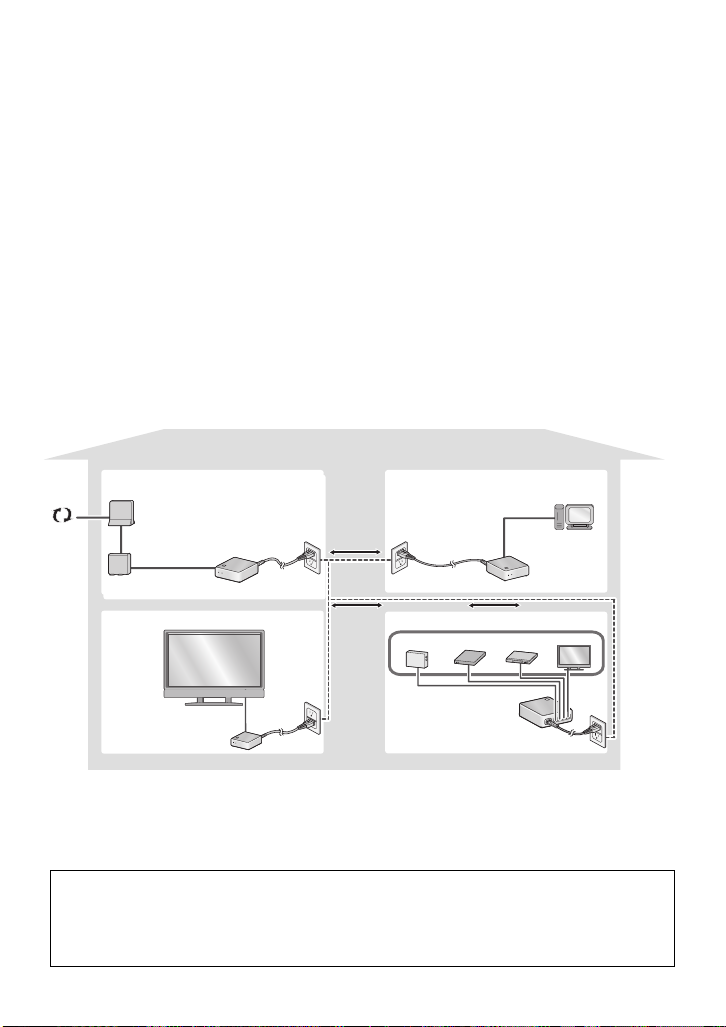
Thank you for purchasing a SHARP PLC (PowerLine Communication)
adapter kit.
The SHARP PLC adapter kit lets you use the existing electrical wiring in
your house to create a home network. Simply plug the adapters into
electrical outlets at the desired locations, and then connect your computer
and other devices to the adapters with LAN cables (two LAN cables are
provided).
If you have Broadband Internet
service, connect your router to one of
the adapters to allow all your network
Data can be exchanged at
speeds of up to 85 Mbps
on your powerline network.
devices to access the Internet.
Internet
Connect a network-enabled
AQUOS LCD-TV to your
powerline network with ease.
PLC adapter
PLC adapter
Up to four devices can
be connected to the
HN-VA400U adapter.
Two adapters are provided in the kit. Additional adapters (HN-VA400U/
HN-VA100U) can be purchased to expand your network. A total of 16
adapters (including the adapters in this kit) can be used.
2
Page 5
Unpacking Checklist
Unpacking Checklist
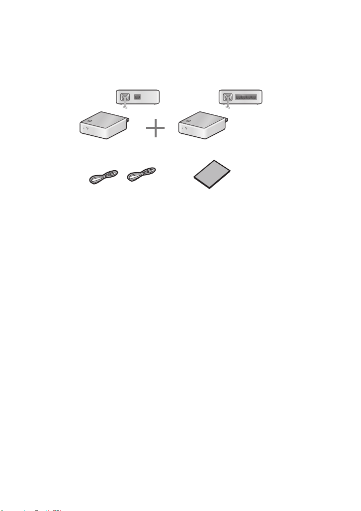
1-port PLC adapter
(HN-VA100U)
LAN
POWER
LAN cables (2): 59.1" (1.5 m)
4-port PLC adapter
(HN-VA400U)
POW
ER
Operation manual
LAN1 LAN2 LAN3 LAN4
(Part order number: QCNWG337DXHZZ)
Safety Information
Do not disassemble the adapter or attempt any procedures not described
in this manual. Refer all servicing to qualified service personnel.
Do not install or use the adapter near water, or when you are wet. For
example, do not install the adapter near a bath tub, kitchen sink or in a wet
basement. Do not spill any liquids on the adapter.
Unplug the adapter from the electrical outlet and consult a qualified
service representative if any of the following situations occur:
- Liquid has been spilled into the adapter or the adapter has been
exposed to rain or water.
- The adapter produces odors, smoke, or unusual noises.
- The power cord is frayed or damaged.
Do not install the adapter near heat sources such as radiators or stoves.
Do not place on top of other electrical devices.
Do not touch the adapter or the power cord during a lightning storm.
Do not use the adapter outdoors.
3
Page 6
Electrical Interference Information
Do not cover the adapter with a blanket or cloth. Excessive heating may
result and cause fire.
The power outlet must be installed near the adapter and must be easily
accessible.
Do not connect a cable other than a LAN cable to the LAN port on the
adapter. Connecting a different type of cable may cause the adapter to
overheat and result in fire.
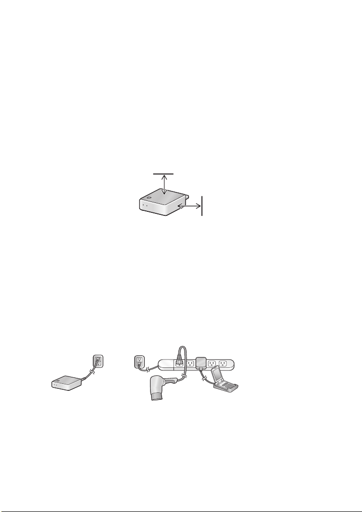
Keep at least 4 inches free around the sides and top of the adapter to
allow air circulation and cooling.
4 inches
4 inches
Electrical Interference Information
Devices that may interfere with the powerline network
Cell phone chargers, battery chargers, vacuums, power tools, hair dryers,
and other appliances may cause noise on your power line that will affect
the performance and communication speed of the adapters. It is
recommended that you use noise filters between these devices and the
electrical outlets where they are plugged in.
PLC adapter
Power strip with
built-in noise filter
Devices that may be affected by the powerline network
The powerline network may interfere with the operation of short-wave
radio, wireless devices such as cordless mice, cordless keyboards and
remote controls, and other devices connected to the same power line
such as touch lamps and dimmers.
4
Page 7

Network Security
Network Security
To prevent others using nearby power lines from accessing or
eavesdropping on your network, only adapters that have been registered
are permitted to connect to the network. In addition, the adapters
communicate using 128-bit AES encryption. Encryption is automatically
enabled when an adapter is registered on your network. (Note that
although 128-bit AES encryption provides a high level of security, it does
not guarantee 100% protection against unauthorized access to your
network.)
♦The adapters in your SHARP PLC adapter kit have been registered at
the factory and 128-bit AES encryption has been enabled.
♦In the event that you transfer one of your adapters to another person or
send an adapter out for service, it is recommended that you cancel the
registration of the adapter (see page 18).
♦If you lose an adapter, it is recommended that you cancel the
registration of your remaining adapters (see page 18) and then reregister the adapters.
Compatibility with other PLC systems
The PLC adapters use the HomePlug® AV 1.1
standard to communicate.
The PLC adapters cannot communicate with adapters that use a previous
HomePlug standard. However, the PLC adapters can coexist on the same
power line with previous HomePlug adapters without mutual interference.
The PLC adapters cannot communicate or coexist with adapters that use
a standard other than HomePlug AV.
The SHARP PLC adapter kit is only for use in the U.S.A.
5
Page 8
A Look at the PLC Adapter
A Look at the PLC Adapter
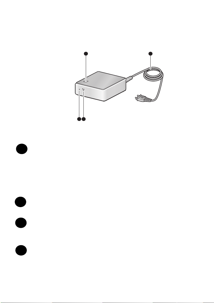
Front
1 4
POWER
2 3
SET button
1
This button is used to register the adapter on the network.
The two adapters in the HN-VA401SU kit have already been
registered. Registration using the SET button is only necessary
when you have purchased an additional adapter, or have canceled
the registration of an adapter. (The SET button is also used to
cancel the network registration of the adapter.)
POWER indicator
2
This lights green when the power is on (see page 16).
PLC indicator
3
This lights steadily when communication is possible, and blinks
when communication is taking place (see page 16).
Power cord
4
Plug this into an electrical outlet to connect the adapter to the
network.
6
Page 9

Rear
A Look at the PLC Adapter
LAN
LA
N
1L
A
N
2
L
A
N
3
LA
N
4
5
LAN ports
5
Connect network devices such as a computer, router, and TV to
these ports using LAN cables. (Two LAN cables are provided;
please purchase additional cables separately as needed.)
Note: The HN-VA100U adapter has only one LAN port.
♦The indicator at the bottom right of each LAN port blinks while
communication is taking place:
Blinks green: Communicating by 100BASE-TX
Blinks orange or red: Communicating by 10BASE-T
If both indicators (at the bottom left and right of each LAN port)
are off, the power is either off or the adapter is not connected to
the network correctly.
7
Page 10

Installation
Installation
1
Plug the power cords of the adapters into electrical outlets at the desired
locations of your house.
• It is recommended that you plug each adapter directly into an electrical
outlet. Plugging the adapters into a surge protector or other device may
impair performance. (The adapters have their own surge protection.)
• The POWER indicator on each adapter will blink orange and green while
the adapter starts up.
Do not plug the
adapter into the same
outlet as another AC
adapter or charger
Do not plug the
adapter into a power
strip with a built-in
noise filter
Do not plug the
adapter into the same
power strip as
another AC adapter
or charger
If you already have a HomePlug AV 1.1 network
If you are adding the adapters to an existing HomePlug AV 1.1 network,
you must first cancel the registration of the adapters (page 18), and then
register them using an existing adapter on the network (page 11).
8
Page 11

Installation
POWER
2
Make sure that the PLC indicator on each adapter lights steady green. This
indicates that the adapter is able to communicate.
• To be able to communicate, the adapter must be registered. The two
adapters
you are adding a separately purchased adapter, see page
in the HN-VA401SU kit have been registered at the factory. If
11 to register
the adapter.
3
For each device (router, computer, network TV, etc.) that you wish to
connect to your home network, insert one end of a LAN cable into the LAN
port on the device and insert the other end into a LAN port on one of the
adapters. Firmly insert the cable ends until they “click” into place.
• Two LAN cables are provided in the kit. If you need additional cables,
please purchase 10BaseT-100BaseTX straight-through (regular) cables.
Router
Computer, network TV, etc.
LAN1 LAN2
LAN3 LAN4
L
A
N
9
Page 12

Installation
Note: Do not connect two PLC adapters together by a LAN cable
L
A
N
L
A
N
♦The maximum distance (length of power line) over which PLC adapters
can communicate is about 492 ft. (150 m). However, this will vary
depending on line conditions such as the amount of noise on your
power lines.
♦A communication speed of up to 85 Mbps is possible. However, the
distance between adapters, noise on the line, and other factors may
cause slower speeds. If you find that communication is not satisfactory,
try plugging the adapter into a different outlet.
♦Communication may be slow or impossible on some power line
systems. In particular, if your power lines consist of two different
systems of differing phase, or if lines are separated by a breaker or
other equipment, communication between the two systems or lines may
be slow or impossible. In this case, try plugging the adapter into a
different outlet.
10
Page 13

Registering an Additional Adapter
POWER
Registering an Additional Adapter
If you purchase an additional adapter, follow the steps below to register
the adapter. The new adapter cannot be used until it is registered.
♦Up to 16 adapters can be used on one network.
1
Plug the new adapter into an outlet next to one of the existing adapters.
• Check the PLC indicator on the existing adapter and make sure it is solidly
lit or blinking (registration is not possible if the existing adapter is not able to
communicate normally on the network).
Existing adapter
2
Hold down the SET button on the existing adapter for about 2 seconds and
then release it.
• When you release the SET button, the POWER indicator will blink.
• Do not hold the SET button down too long (if it is held down for about 10
seconds, the registration will be cleared).
SET
New adapter
11
Page 14

Registering an Additional Adapter
SET
POWER
3
Hold down the SET button on the new adapter for about 2 seconds and
then release it (this must be done within 2 minutes of completing Step 2).
• When you release the SET button, the POWER indicator will blink and
registration will begin. During registration, communication on the network
may stop temporarily. Registration may take up to 30 seconds.
• Important: Do not remove either adapter from the outlet while registration
is taking place.
POWER
4
When registration is completed, the POWER indicator on both adapters
will stop blinking and the PLC indicator on both adapters will light solidly or
blink. Remove the new adapter from the outlet and plug it into the outlet
where you wish to use it.
• If the PLC indicator on the new adapter does not light up and instead the
POWER indicator blinks in the pattern
2 blinks OFF 2 blinks OFF ...
registration was not successful. Cancel the registration of the adapter as
explained on page 18, and then try registration again.
12
Page 15

Troubleshooting
Troubleshooting
If you have any problems with the adapter, first refer to the following
troubleshooting guide. If you cannot solve the problem, call 1-800-BE-SHARP.
Problem Solution
The POWER indicator is
off even though the
adapter is plugged into an
outlet.
Communication is not
possible on the network
• Make sure that the adapter is plugged into a
standard (120 V, 60 Hz) outlet.
• Make sure the outlet has power. Try plugging
the adapter into a different outlet.
• If the temperature of the adapter rises to the
point that operation will be impaired, the
adapter will automatically stop operating.
Unplug the adapter and let it cool. Once the
adapter has cooled, try using it again.
•Is the PLC indicator on or blinking? If not, try
plugging the adapters into outlets that are as
close to each other as possible. If the PLC
indicator still does not light, it is possible that
the registration of an adapter has been
canceled. Re-register the adapter as
explained on page 11. If the PLC indicator
lights in some outlets but not in others, it is
likely that some condition of your power lines
prevents communication in some outlets. Use
the adapters in outlets where communication
is possible.
• If the PLC indicator lights normally but the
LAN port indicators do not light, make sure
the LAN cables are firmly inserted in their
ports. Make sure that the LAN cables are
category 5 or 6 cables that support
100BASE-TX.
13
Page 16

Troubleshooting
Connection to the Internet
is not possible.
Network communication is
slow or intermittent.
• To connect to the Internet via the network,
you must have a Broadband Internet
connection (cable or DSL). Make sure your
cable or DSL modem is correctly connected
to your router, and that your router is correctly
connected to one of the PLC adapters. No
special settings are required to connect to
the Internet through the PLC network,
however, your computers and router must be
correctly set to access the Internet (check
with your Internet service provider).
• If any of the adapters are connected to a
power strip with a surge protector or noise
filter, communication may be impaired.
Connect all adapters directly to their
electrical outlets. If you must plug an adapter
into a power strip, use a power strip without a
noise filter or surge protector, and one that
does not have a long cord.
• Other appliances may be causing noise on
your power lines. Use noise filters for
appliances such as
cell phone chargers,
battery chargers, vacuums, power tools,
and hair dryers, and use these appliances
as far as possible from the PLC adapters.
14
• If adapters are located too far apart,
communication may be impaired. The
maximum distance is 492 ft. (150 m),
however, this may vary depending on line
conditions.
• Are you also using PLC adapters of a
different standard on your power lines? This
may impair communication. If you must use
other adapters, use them as far away as
possible from your SHARP PLC adapters.
Page 17

Troubleshooting
A PLC adapter does not
operate, or does not
operate correctly.
Other devices such as
touch lights or dimmers do
not operate correctly.
The PLC indicator blinks
even though no data is
being sent over the
network.
• Unplug the adapter from the electrical outlet
for at least 10 seconds and then plug it back
in. This will restart the adapter.
If the adapter still does not operate correctly,
cancel the registration as explained on page
18, and then re-register it as explained on
page 11.
If the adapter still does not operate correctly,
call 1-800-BE-SHARP.
• Try plugging the appliance into a different
outlet. Use the appliance as far away as
possible from the PLC adapters.
• The adapters periodically communicate with
each other to check the connection, and this
causes the PLC indicator to blink. This is
normal.
• AES 128-bit encryption is used to prevent
outsiders from gaining access to your
network. However, this does not guarantee
100% protection. If you are concerned that
somebody may be trying to use your network,
remove the adapters from the outlets when
you are not using the network.
15
Page 18

Indicators on the PLC adapters
Indicators on the PLC adapters
POWER indicator
ON The power is on
Blinking • The adapter is starting up (the adapter blinks
orange and green during startup).
• An adapter is being registered (see page 11).
OFF The power is off.
2 blinks > OFF > 2 blinks >
OFF...
Registration of a new adapter failed (see page
11).
PLC indicator
The PLC indicator indicates both the status of PLC communication and
the communication speed.
Communication status
ON Communication is possible.
Blinking The adapter is communicating on the network
(the interval of blinking may vary depending on
communication conditions).
OFF The adapter is not connected to the network or
the power is off.
16
Page 19

Indicators on the PLC adapters
Communication speed*
Green The adapters are able to communicate at a
speed of 30 Mbps or higher.
Orange The adapters are able to communicate at a
speed of 10 to 30 Mbps.
Red The adapters are able to communicate at a
speed of no more than 10 Mbps.
* The speed indication is only correct after communication has begun. The speed
indicated is an approximate maximum for data transfer by UDP between
adapters. It is not the effective speed between computers on the network. If
more than two adapters are connected, it is the speed between the two adapters
with the best communication speed.
17
Page 20

Canceling the Registration of an Adapter
SET
Canceling the Registration of an Adapter
To cancel the network registration of an adapter, follow the steps below.
This should be done in the following situations:
♦You attempted to register a separately purchased adapter, but
registration failed.
♦You wish to change the registration of an adapter to a different network.
♦You are going to discard or give an adapter to someone else, or have an
adapter serviced.
♦If you suspect that someone is using an adapter to gain unauthorized
access to your network, cancel the registration of all adapters on your
network and then re-register the adapters.
Note: Perform the following steps with the adapter plugged into an
electrical outlet.
1
On the adapter whose registration you want to cancel, hold down the SET
button on the adapter until the POWER indicator turns off (about 10
seconds) and then release the button.
2
Wait until the POWER indicator turns back on. Registration cancellation is
now complete.
• Important: Do not remove the adapter from the outlet until the POWER
indicator turns on, as cancellation may not be complete. (It may take as
long as 30 seconds for cancellation to be completed.)
• To use the adapter again, you will need to register it as explained on page
11.
18
Page 21

Specifications
Communication standard HomePlug AV 1.1
*1
Communication speed
PHY rate (theoretical value): 200 Mbps max.
Effective speed:
85 Mbps max. (UDP)
55 Mbps max. (TCP)
Specifications
*2
Maximum number of
connectable adapters
16 adapters
*3
Frequency band 2 MHz to 30 MHz
Access method CSMA/CA (PLC interface side)
Encryption method AES 128-bit
Modulation method Windowed OFDM
Error correction method Advanced turbo coding
Communication range 492 ft. (150 m) maximum (varies depending
on environment)
LAN interface
IEEE 802.3u (100Base-TX)
IEEE 802.3 (10Base-T)
MDI/MDI-X Automatic detection
CSMA/CD (access method on LAN port side)
*1
The actual communication speed (effective communication speed) may be
affected by power line conditions (structure of equipment, length of lines, etc.),
other electrical appliances, and network conditions.
UDP is a data communication protocol used on the Internet, and although the
data communication reliability of UDP is low, processing is simple and the
communication speed is fast, and thus UDP is often used for video streaming.
TCP is also a data communication protocol used on the Internet, and although
TCP is slower than UDP, it has higher reliability and thus is commonly used for
general communication.
*2
Measured using FTP from a Windows® PC to a Linux® server.
*3
The maximum number of adapters is a recommended value. As the number of
PLC adapters and other devices connected to the network increases, the
communication speed slows.
19
Page 22

Specifications
Number of LAN ports HN-VA100U: 1 port
HN-VA400U: 4 ports
Power requirements 120 V AC, 60 Hz
Power consumption HN-VA100U: 4.4 W maximum
HN-VA400U: 5.0 W maximum
Dimensions (W x H x D) 118 mm x 42 mm x 91 mm (excluding
protrusions)
Weight HN-VA100U: 340 g (approx.)
HN-VA400U: 350 g (approx.)
Operating temperature 0° - 40°C
Humidity 25% - 85% (no condensation)
20
Page 23

U.S.A. only
LIMITED WARRANTY
SHARP ELECTRONICS CORPORATION warrants to the first end user purchaser that this Sharp
brand product (the "Product"), when shipped in its original container, will be free from defective
workmanship and materials, and agrees that it will, at its option, either repair the defect or replace
the defective Product or part thereof with a new or remanufactured equivalent at no charge to the
purchaser for parts or labor for the period(s) set forth below.
This warranty does not apply to any appearance items of the Product nor to the additional excluded
item(s) set forth below nor to any product the exterior of which has been damaged or defaced,
which has been subjected to misuse, abnormal service or handling, or which has been altered or
modified in design or construction.
In order to enforce the rights under this limited warranty, the purchaser should follow the steps set
forth below and provide proof of purchase to the servicer.
To the extent permitted by applicable state law, the warranties set forth herein are in lieu of, and
exclusive of, all other warranties, express or implied. Specifically, ALL OTHER WARRANTIES
OTHER THAN THOSE SET FORTH ABOVE ARE EXCLUDED. ALL EXPRESS AND IMPLIED
WARRANTIES INCLUDING THE WARRANTIES OF MERCHANTABILITY, FITNESS FOR USE,
AND FITNESS FOR A PARTICULAR PURPOSE ARE SPECIFICALLY EXCLUDED. If, under applicable state law, implied warranties may not validly be disclaimed or excluded, the duration of such
implied warranties is limited to the period(s) from the date of purchase set forth below.
Neither the sales personnel of the seller nor any other person is authorized to make any warranties
other than those described above, or to extend the duration of any warranties beyond the time
period described above on behalf of Sharp.
The warranties described herein shall be the sole and exclusive warranties granted by Sharp and
shall be the sole and exclusive remedy available to the purchaser. Correction of defects, in the
manner and for the period of time described herein, shall constitute complete fulfillment of all
liabilities and responsibilities of Sharp to the purchaser with respect to the Product, and shall
constitute full satisfaction of all claims, whether based on contact, negligence, strict liability or
otherwise. In no event shall Sharp be liable, or in any way responsible, for any damages or defects
in the Product which were caused by repairs or attempted repairs performed by anyone other than
an authorized servicer. Nor shall Sharp be liable or in any way responsible for any incidental or
consequential economic or property damage. Some states do not allow limits on warranties or on
remedies for breach in certain transactions; in such state the limits herein may not apply.
Your Product:
Warranty Period for this Product:
Where to obtain service:
To find out the location of the nearest Shar p Authorized Servicer,
call Sharp toll free at 1-800-BE-SHARP.
What to do to obtain service:
Be sure to have proof of purchase available. If you ship or mail the
Product, be sure it is packaged carefully.
PowerLine Ethernet Adapter Kit
One year parts and labor from date of purchase.
At a Sharp Authorized Servicer located in the United States.
Ship (prepaid) or carry in your Product to a Sharp Authorized Servicer.
For product information, customer assistance or to purchase accessories, please visit
http://www.sharpusa.com or call 1-800-BE-SHARP.
SHARP ELECTRONICS CORPORATION
Sharp Plaza,
Mahwah, New Jersey 07430-1163
Page 24

SHARP ELECTRONICS CORPORATION
Sharp Plaza, Mahwah, New Jersey 07430-1163
1-800-BE-SHARP
http://www.sharpusa.com
SHARP CORPORATION
Please record the model number and serial number below, for easy
reference, in case of loss or theft. These numbers are located on the
rear side of the unit. Space is also provided for other relevant
information.
Model Number
Serial Number
Date of Purchase
Place of Purchase
FOR YOUR RECORDS
HN-VA401SU
PRINTED IN THAILAND
(TINSE4561XHTZ)
 Loading...