

Page 1
GP2Y0A21YK0F
1
GP2Y0A21YK0F
Distance Measuring Sensor Unit
Measuring distance: 10 to 80 cm
Analog output type
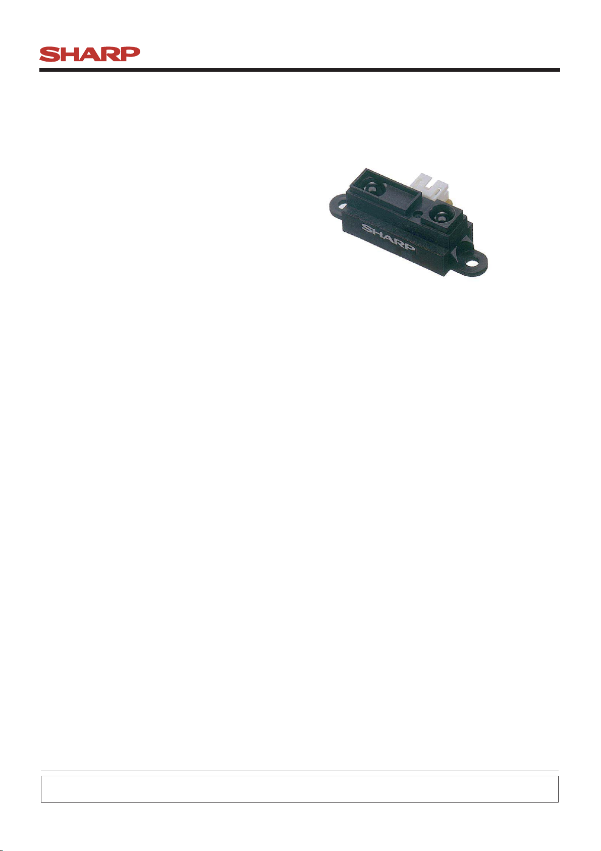
■Description
GP2Y0A21YK0F is a distance measuring sensor unit,
composed of an integrated combination of PSD
(position sensitive detector) , IRED (infrared emitting
diode) and signal processing circuit.
The variety of the reflectivity of the object, the
environmental temperature and the operating duration
are not influenced easily to the distance detection
because of adopting the triangulation method.
This device outputs the voltage corresponding to the
detection distance. So this sensor can also be used as
a proximity sensor.
■Features
1. Distance measuring range : 10 to 80 cm
2. Analog output type
3. Package size : 29.5×13×13.5 mm
4. Consumption current : Typ. 30 mA
5. Supply voltage : 4.5 to 5.5 V
■Agency approvals/Compliance
1. Compliant with RoHS directive (2002/95/EC)
■Applications
1. Touch-less switch
(Sanitary equipment, Control of illumination, etc. )
2. Robot cleaner
3. Sensor for energy saving
(ATM, Copier, Vending machine)
4. Amusement equipment
(Robot, Arcade game machine)
Notice The content of data sheet is subject to change without prior notice.
In the absence of confirmation by device specification sheets, SHARP takes no responsibility for any defects that may occur in equipment using any SHARP
devices shown in catalogs, data books, etc. Contact SHARP in order to obtain the latest device specification sheets before using any SHARP device.
Sheet No.: E4-A00201EN
Date Dec.01.2006
©SHARP Corporation
Page 2
GP2Y0A21YK0F
2
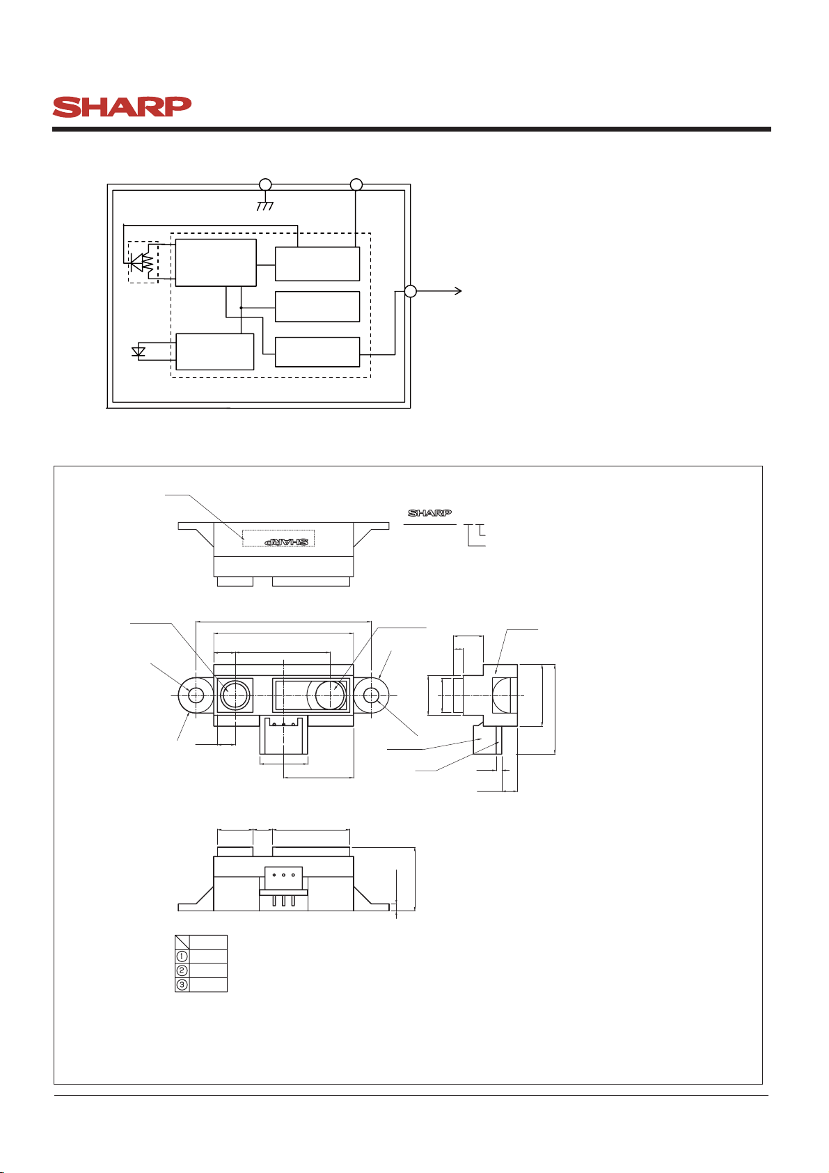
■Block diagram
PSD
Signal
processing circuit
LED drive circuit
LED
■Outline Dimensions
(Stamp)
GND
Voltage regulator
Oscillation circuit
Output circuit
Distance measuring IC
Vcc
2Y0A21 F 4Z
Vo
Stamp(Example)
2Y0A21 F 4 Z
Model name
Month(1 to 9,X,Y,Z)
Year(2005:5)
(Unit : mm)
Light emitter
φ3.2hole
*
4.5
R3.75
3.75
7.5 4.15 16.3
Connector signal
signal name
VO
GND
CC
V
37
29.5
*
20±0.1
10.1
14.75
①②③
Connector :
J.S.T.TRADING COMPANY,LTD,
S3B-PH
Light detector
R3.75
φ3.2hole
Connector
13.5
2-1.5
PWB
6.3
2
8.4
7.2
Materials
Lens :Acrylic acid resin
(Visible light cut-off resin)
Case :Carbonic ABS
(Conductive resin)
PWB :Paper phenol
1.2
(3.3)
Lens case
13
-0.3
+0.5
(18.9 )
Note 1. The dimensions marked * are described the dimensions of lens center position.
Note 2. Unspecified tolerances shall be ± 0.3 mm.
Note 3. The dimensions in parenthesis are shown for reference.
Product mass : Approx. 3.6g
Sheet No.: E4-A00201EN
Page 3
GP2Y0A21YK0F
3
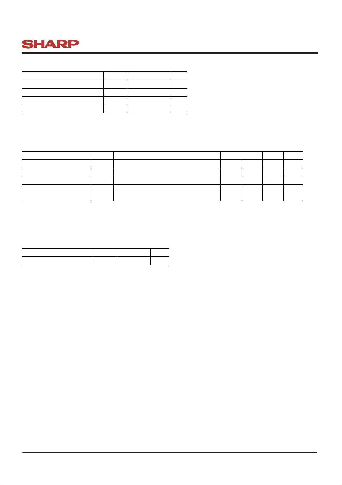
■Absolute Maximum Ratings
Parameter
Supply voltage
Output terminal voltage
Operating temperature
Storage temperature
Symbol Rating Unit
V
CC
V
O
T
opr
T
stg
■Electro-optical Characteristics
(Ta=25℃,VCC=5V)
-0.3 to +7 V
-0.3 to VCC+0.3
-10 to +60
-40 to +70
V
℃
℃
(Ta=25℃,VCC=5V)
Parameter Symbol Conditions MIN. TYP. MAX. Unit
Average supply current
I
CC
L=80cm (Note 1) ― 30 40 mA
Distance measuring ΔL(Note 1)10― 80 cm
Output voltage
Output voltage differential
V
ΔV
O
O
Output voltage differece between
L=80cm (Note 1) 0.25 0.4 0.55 V
L=10cm and L=80cm (Note 1)
1.65 1.9 2.15 V
* L : Distance to reflective object
Note 1 : Using reflective object : White paper (Made by Kodak Co., Ltd. gray cards R-27・white face, reflectance; 90%)
■Recommended operating conditions
Parameter Symbol Rating Unit
Supply voltage
V
CC
4.5 to 5.5 V
Sheet No.: E4-A00201EN
Page 4

Fig. 1 Timing chart
4
Vcc(Power supply)
GP2Y0A21YK0F
38.3ms±9.6ms
Distance measuring operating
Vo(Output)
First measurement
Second
measurement
MAX 5.0ms
nth
measurement
Second output First outputUnstable output
nth
output
Sheet No.: E4-A00201EN
Page 5

Fig. 2 Example of distance measuring characteristics(output)
5
3.5
White paper (Reflectance ratio 90%)
GP2Y0A21YK0F
3
Gray paper (Reflectance ratio 18%)
2.5
2
1.5
1
Output voltage (V)
0.5
0
0102030 5040 60 70 80
Distance to reflective object L(cm)
3.5
6cm
3
7cm
8cm
2.5
10cm
5cm
2
1.5
Output voltage (V)
25cm
1
40cm
50cm
0.5
80cm
0
0
15cm
20cm
30cm
White paper (Reflectance ratio 90%)
Gray paper (Reflectance ratio 18%)
0.05
0.1
Inverse number of distance (1/cm)
0.15
0.2
Sheet No.: E4-A00201EN
Page 6

GP2Y0A21YK0F
6
■Notes
●Advice for the optics
• The lens of this device needs to be kept clean. There are cases that dust, water or oil and so on deteriorate
the characteristics of this device. Please consider in actual application.
• Please don’t do washing. Washing may deteriorate the characteristics of optical system and so on.
Please confirm resistance to chemicals under the actual usage since this product has not been designed against washing.
●Advice for the characteristics
• In case that an optical filter is set in front of the emitter and detector portion, the optical filter which has the most
efficient transmittance at the emitting wavelength range of LED for this product (λ = 870 ± 70nm), shall be
recommended to use. Both faces of the filter should be mirror polishing. Also, as there are cases that the characteristics
may not be satisfied according to the distance between the protection cover and this product or the thickness of the
protection cover, please use this product after confirming the operation sufficiently in actual application.
• In case that there is an object near to emitter side of the sensor between sensor and a detecting object, please use this
device after confirming sufficiently that the characteristics of this sensor do not change by the object.
• When the detector is exposed to the direct light from the sun, tungsten lamp and so on, there are cases that it can not
measure the distance exactly. Please consider the design that the detector is not exposed to the direct light from such
light source.
• Distance to a mirror reflector can not be sometimes measured exactly.
In case of changing the mounting angle of this product, it may measure the distance exactly.
• In case that reflective object has boundary line which material or color etc. are excessively different, in order to
decrease deviation of measuring distance, it shall be recommended to set the sensor that the direction of boundary line
and the line between emitter center and detector center are in parallel.
(Incorrect) (Correct)
• In order to decrease deviation of measuring distance by moving direction of the reflective object, it shall be
recommended to set the sensor that the moving direction of the object and the line between emitter center and
detector center are vertical.
(Incorrect)
(Moving direction)
(Correct)
(Moving direction)
●Advice for the power supply
• In order to stabilize power supply line, we recommend to insert a by-pass capacitor of 10μF or more
between Vcc and GND near this product.
●Notes on handling
• There are some possibilities that the internal components in the sensor may be exposed to the excessive mechanical
stress. Please be careful not to cause any excessive pressure on the sensor package and also on the PCB while
assembling this product.
Sheet No.: E4-A00201EN
Page 7

●Presence of ODC etc.
7
This product shall not contain the following materials.
And they are not used in the production process for this product.
Regulation substances : CFCs, Halon, Carbon tetrachloride, 1.1.1-Trichloroethane (Methylchloroform)
Specific brominated flame retardants such as the PBB and PBDE are not used in this product at all.
This product shall not contain the following materials banned in the RoHS Directive (2002/95/EC).
• Lead, Mercury, Cadmium, Hexavalent chromium, Polybrominated biphenyls (PBB),
Polybrominated diphenyl ethers (PBDE).
GP2Y0A21YK0F
Sheet No.: E4-A00201EN
Page 8

■Package specification
8
Package composition
Tray
Product
GP2Y0A21YK0F
Pad
(2 sheeets/case: top and bottom)
Tray put products
(10-tray/case)
Pad
(10 sheeets/case)
(Fig.2)
(Fig.1)
(Fig.3)
Packing case
Model No.
Quantity
Date
Packaging method
1.Put products of 100pcs. in tray. packing method is showed in the above fig.(Fig.1)
2.Put them(10-tray) in the packing box. Put pads on their top and bottom.
And put pads on each trays(Total 10 sheets) (Fig.2).
3.Seal the packing box with craft tape.
Print the model No.,quantity,inspection date (1000 pcs./a packing box)(Fig.3).
Craft tape
Sheet No.: E4-A00201EN
Page 9

■Important Notices
9
GP2Y0A21YK0F
· The circuit application examples in this publication are
provided to explain representative applications of
SHARP devices and are not intended to guarantee any circuit
design or license any intellectual property rights. SHARP
takes no responsibility for any problems related to any
intellectual property right of a third party resulting from the use
of SHARP's devices.
· Contact SHARP in order to obtain the latest device specification sheets before using any SHARP device. SHARP
reserves the right to make changes in the specifications,
characteristics, data, materials, structure, and other
contents described herein at any time without notice in
order to improve design or reliability. Manufacturing
locations are also subject to change without notice.
· Observe the following points when using any devices in this
publication. SHARP takes no responsibility for damage
caused by improper use of the devices which does not meet the
conditions and absolute maximum ratings to be used specified
in the relevant specification sheet nor meet the following conditions:
(i) The devices in this publication are designed for use in
general electronic equipment designs such as:
--- Personal computers
--- Office automation equipment
--- Telecommunication equipment [terminal]
--- Test and measurement equipment
--- Industrial control
--- Audio visual equipment
--- Consumer electronics
(ii) Measures such as fail-safe function and redundant design
should be taken to ensure reliability and safety when SHARP
devices are used for or in connection
with equipment that requires higher reliability such as:
--- Transportation control and safety equipment (i.e.,
aircraft, trains, automobiles, etc.)
--- Traffic signals
--- Gas leakage sensor breakers
--- Alarm equipment
--- Various safety devices, etc.
(iii) SHARP devices shall not be used for or in
connection with equipment that requires an extremely high
level of reliability and safety such as:
--- Space applications
--- Telecommunication equipment [trunk lines]
--- Nuclear power control equipment
--- Medical and other life support equipment (e.g.,
scuba).
· If the SHARP devices listed in this publication fall
within the scope of strategic products described in the
Foreign Exchange and Foreign Trade Law of Japan, it is
necessary to obtain approval to export such SHARP devices.
· This publication is the proprietary product of SHARP and
is copyrighted, with all rights reserved. Under the copyright laws, no part of this publication may be reprodu ced or t r ansmit t ed in an y form or by any means,
electronic or mechanical, for any purpose, in whole or in
part, without the express written permission of SHARP.
Express written permission is also required before any use
of this publication may be made by a third party.
· Contact and consult with a SHARP representative if there
are any questions about the contents of this publication.
Sheet No.: E4-A00201EN
 Loading...