

Sharp GF-A2Z(S),GF-A2Z(G) Service Manual
mmM
SHARI=
SERVICE
MANUAL
,
S5452G F-A2ZSl
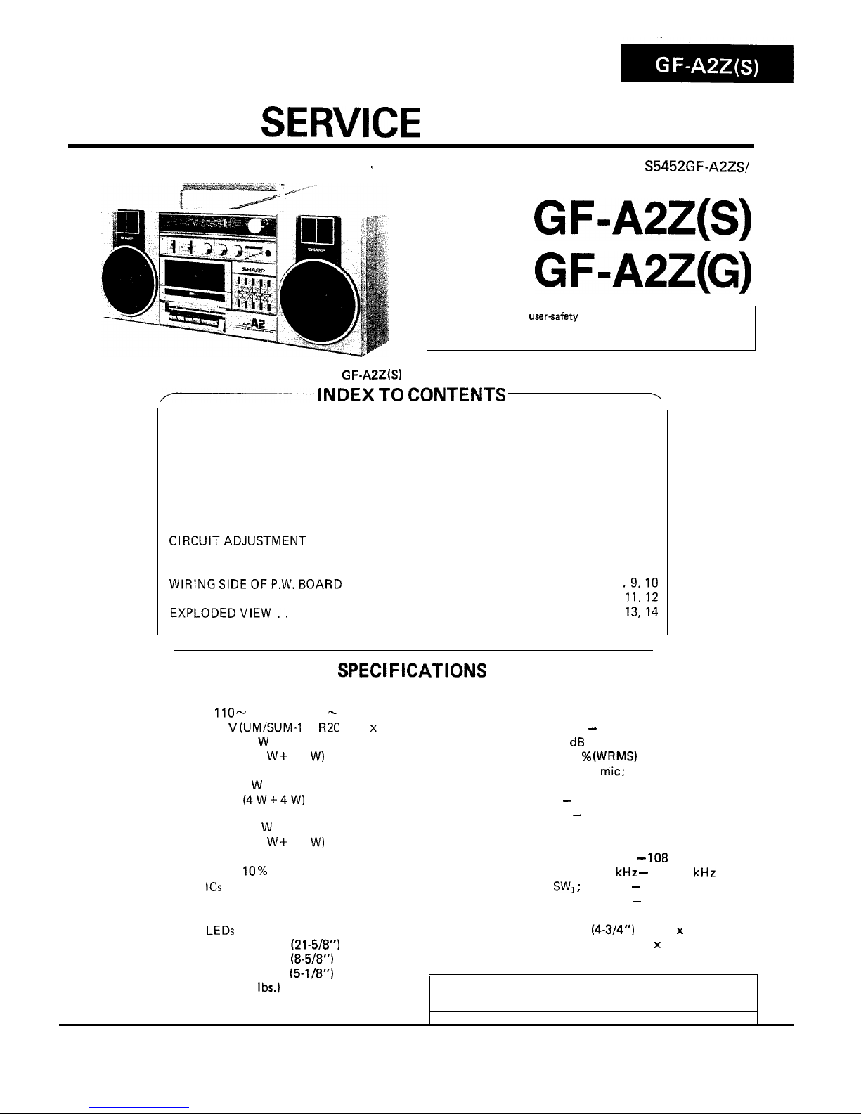
GF-A2Z(S)
GF-A2Z(G)
In the interests of usersafety the set should be restored to its
original condition and only parts identical to those specified be
used.
Photo: G
F-APZ(S)
/-INDEX
TO CONTENTS
--.
Page
SPECIFICATIONS
...............................................
1
NAMESOFPARTS
..............................................
2
VOLTAGE SELECTION
...........................................
2
STRINGING OF DIAL CORD
.......................................
2
DISASSEMBLY
.................................................
3
BLOCKDIAGRAM
..............................................
4
TEST TAPES FOR MEASUREMENT
..................................
5
MECHANICAL ADJUSTMENT
......................................
5
CIRCUITADJUSTMENT
........................................
5-7
ACPOWERSUPPLYCORD
.........................................
7
NOTES ON SCHEMATIC DIAGRAM
..................................
8
WlRlNGSlDEOFP.W.BOARD
...................................
.9,10
SCHEMATIC DIAGRAM
........................................
II,12
EXPLODEDVIEW..
..........................................
13,14
REPLACEMENT PARTS LIST
....................................
15-18
SPECIFICATIONS
GENERAL
Power source:
Output power:
Semiconductors:
Dimensions:
AC
110 -
127V and 220 - 240V
DC 9 V
(UM/SUM-1
or
R20
type x 6)
PMPO; 15
W
(7.5 w + 7.5
W)
(AC operation)
MPO; 8
W
(4w+4w)
(AC operation)
RMS; 4.6
W
(2.3 W + 2.3
W)
(DC operation
10 %
distortion)
8
ICs
3 Transistors
13 Diodes
6
LEDs
Width; 550 mm
(21-5/8”)
Height; 220 mm
(8-5/8”)
TAPE RECORDER
Tape:
Frequency range:
Signal/noise ratio:
Wow and flutter:
Input impedance:
Loaded impedance:
Headphones;
External speakers;
RADIO
Frequency range:
SPEAKER
Speakers:
Impedance:
Compact cassette tape
80 Hz - 10,000 Hz
36
dB
0.15 %
(WRMS)
External mic: 600 ohms
8 - 25 ohms
3.2 - 8 ohms
FM; 87.6 MHz -
108
MHz
AM; 526.5 kHz - 1606.5 kHz
SW1 ;
2.3 MHz - 7.3 MHz
SW,; 7.3 MHz - 22 MHz
12 cm
(4-3/4”)
woofer x 2
Horn type tweeter x 2
3.2 ohms
Weight:
Depth; 130 mm (5-I
/8”)
3.6 kg (7.9
Ibs.)
without batteries
Specifications for this model are subject to change without
prior notice.
SHARP CORPORATION
FOR A COMPLETE DESCRIPTION OF THE OPERATION OF THIS UNIT,
PLEASE REFER TO THE OPERATION MANUAL.
1.
Built-in Microphone
2. Band Selector Switch
3.
FM
Stereo Indicator
4. Function Selector Switch
5.
Volume Control
6.
Balance Control
7. Fine Tuning Control
8.
Power Indicator
9. Sound Level Meter
10.
Tuning Control
11.
Headphones Jack
12.
Cassette Compartment
13.
Record Button
14.
Rewind Button
15.
Play Button
16.
Fast-Forward Button
17.
Stop/Eject Button
18. Graphic Equalizer Controls
19. Speaker Release Knob
20. External Speaker Terminals
21.
External Microphone Jack
22. FM/SW Telescopic Rod Antenna
23.
Battery Compartment
24. Speaker Cord Holder
25. AC Power Supply Socket
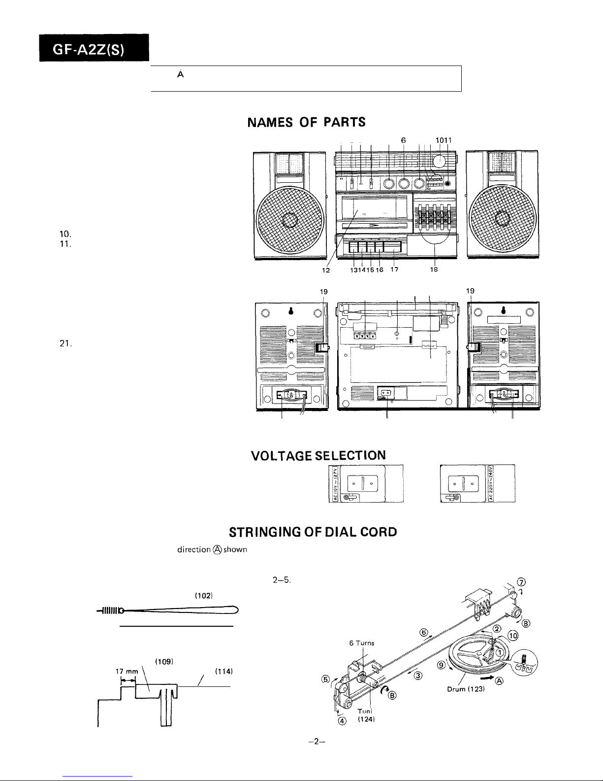
NAMES OF PARTS
1234 5 6
789 1011
Figure 2-l
20
21
22 23
I
I I I
24
25
Figure 2-2
24
VOLTAGE
SELECTION
Before operating the unit on mains,
check
the preset voltage.
If the voltage is different from your local voltage,
adjust the
voltage as follows: Slide the AC power supply socket cover by
slightly loosing the screw to the visible indication of the side
mi
m’:1II
of your local voltage.
Figure 2-3
STRINGING OF DIAL
CORD
1. Turn the drum fully in the
direction@shown
in Fig. 2-4
and stretch its cord over the parts in the numerical order.
2. Then turn the tuning control shaft fully in the direction@
shown in Fig. 2-4 and fix its pointer as shown in Fig.
2-5.
Spring
with Dial Cord
(102)
451 mm
Pointer
(109)
17 mm
Frame
(114)
f9
/
Figure 2-5
ing Control Shaft
Figure 2-4
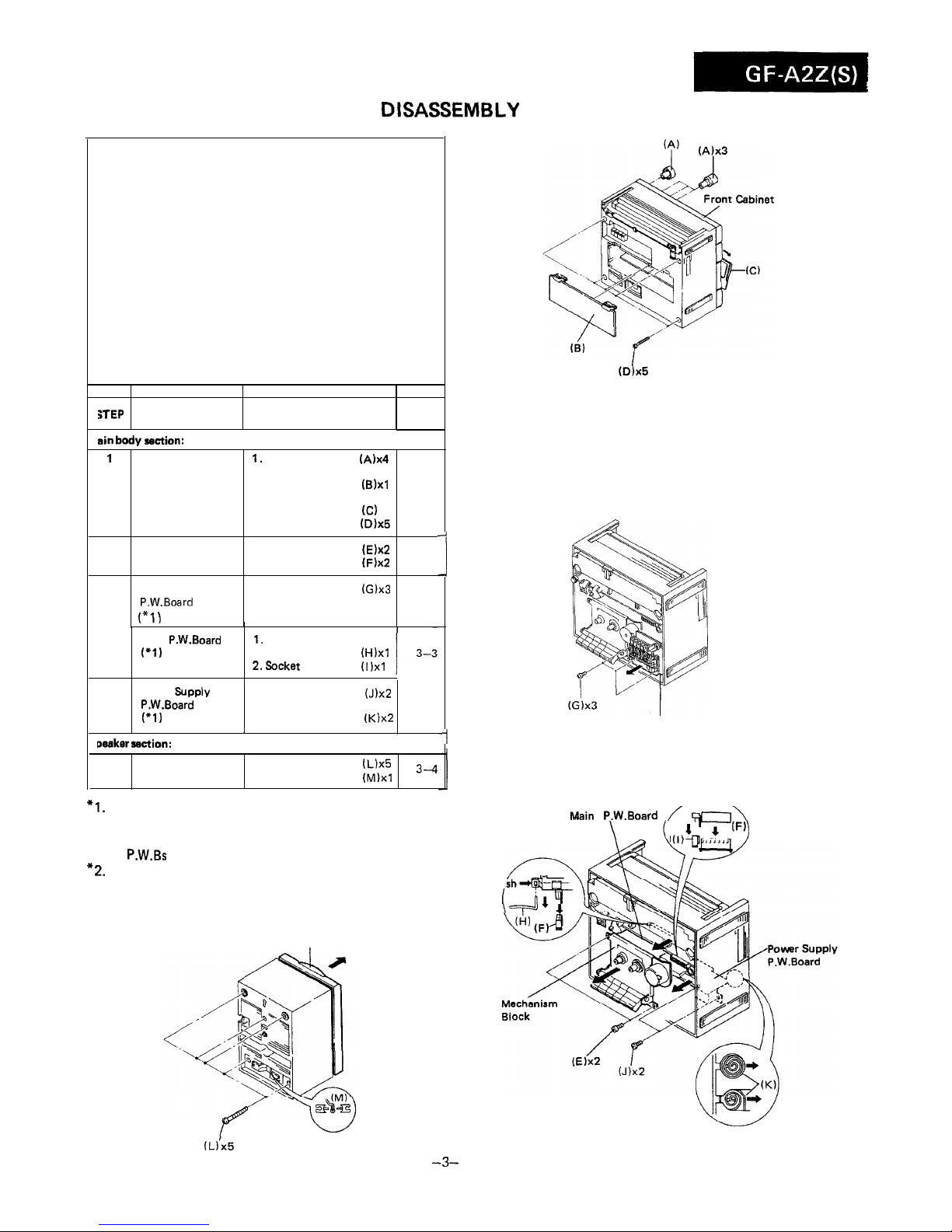
DISASSEMBLY
Caution on Disassembly
Follow the below-mentioned notes when disassembling the
unit and reassembling it, to keep its safety and excellent
performance:
1. Take cassette tape out of the unit.
2. Be sure to remove the power supply plug from the wall
outlet before starting to disassemble the unit and remove
the batteries from the unit.
3. Take off nylon bands or wire holders where they need be
removed when disassembling the unit. After servicing
the unit, be sure to rearrange the leads where they were
before disassembling.
4. Take sufficient care on static electricity of integrated
circuits and other circuits when servicing.
iTEP
REMOVAL
PROCEDURE
FIGURE
1
sin body section:
1
Front cabinet
1.
Knob . . . . . . .
(A)x4
2. Battery compartment
lid
. . . . . . . , .
03)x1
3. Open the cassette
holder . . . . . . . (C)
4. Screw . . . . . . .
(D)x5
3-l
2 Mechanism block 1. Screw . . . . . . .
(E)x2
2. Socket . . . . . .
(F)x2
3-3
Graphic Equalizer 1. Screw (G)x3
P.W.Board
3-2
(“1)
I
3
Main P.W.Board
1.
Record interlocking
(‘1)
lever. . . . . . .
(H)xl
(‘2)
2.Socket
. . . . . .
(1)x1
4
Power Bupply
1. Screw . . . . . . . (J)x~
P.W.Board 2. Battery terminal
(‘1)
spring . . . . . . .
(K)x2
I
,
paaker section:
Front Cabinet
1. Screw , . . . . . .
(L)x5
2. Speaker Cord . .
(~)xl
3--4
-I
*I.
Each P.W.B. should be removed until the parts to be
exchanged can be removed when servicing. If the parts to
be exchanged are in the exchangeable condition, the rest
of
P.W.Bs
need not to be removed.
*2.
When taking the main P.W.B. out the unit, the P.W.B.
cannot be removed unless the every external speaker
terminal knobs located at the rear side are let down.
Front Cabinet
I
(D)x5
Figure 3-l
Graphic Equalizer P.W. Board
Figure 3-2
Vain
P.W.Board /
F‘c7\
. . .
\
Pu
!
(L)‘x5
Figure 3-4
-3-
Figure 3-3
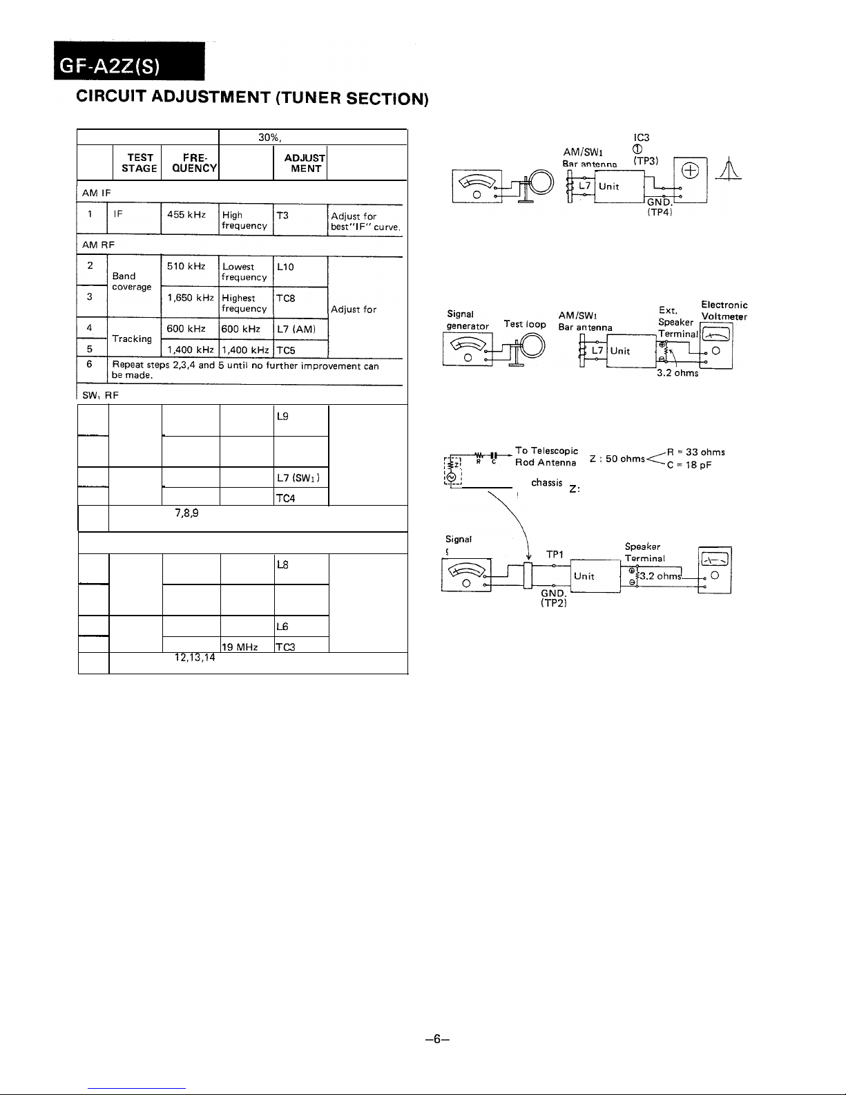
AM IF/RF ADJUSTMENT
SIGNAL GENERATOR
400 Hz, 30%, AM modulated
STEP
S;;gE
FRE-
DIAL
POINTER
A;pNy
QUENCY
SETTING
REMARKS
maximal output
7
2.25 MHz
Lowest
LS
Band
frequency
-
coverage
I
8
7.4 MHz
Highest
TC7
frequency
Adjust for
maximal9output
2.6 MHz
2.6 MHz L7
(SWl)
-
Tracking
-
10
6.0 MHz
6.0 MHz
TC4
11
Repeat steps
78,s
and 10 until no further improvement can
be made.
SW, RF
12
7.2 MHz Lowest
i-8
Band
frequency
-
coverage
13
22.5 MHz Highest
TC6
frequency
Adjust for
14
-maximal output
8.5 MHz
8.5 MHz L6
-
Tracking
15 19 MHz
19MHz TC3
16
Repeat steps
12,13,14
and 15 until no further improvement can
be made.
Sweep
generator
Test loop
AM/SW 1
0
pin Oscilloscope
Figure 6-l AM IF
Figure 6-2 AM RF
8$-j
To
chassis
ground
2 :
Output impedance of signal generator
generator
Ext.
Electronic
Voltmeter
(TP2)
Figure 6-3 SW RF
-6-
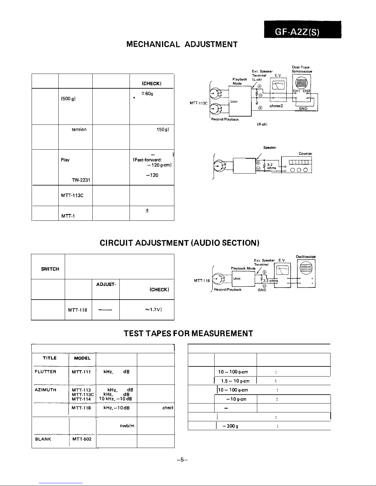
MECHANICAL ADJUSTMENT
l
For the details of the test tapes used for the measurement,
refer to the Table “TEST TAPES FOR MEASUREMENT”.
E.V.: Electronic Voltmeter
ITEM
JIG
ADJUSTMENT
POINTS
REMARKS
(CHECK)
Pinch
roller
pressure
Tension gauge
Pinch roller 370 *
6Og
(500 9)
pressure spring* If the reading
is outside the
range, replace the
pressure spring of
the pinch roller.
Driving
power
Tape tention
measuring
cassette
TW-2412
(More than
150 g1
Torque Torque meter
Play
TW-2111
Fast-forward
TW-2231
Rewind
l-W-2231
(Play:35 - 60 g-cm
(Fast-fo~lard:
70 -
120 g-cm)
(Rewind:
70 -
120
g-cm)
Azimuth
Tape
speed
Test tape
M-f-r-1 13C
Test tape
Ml-T-1
11
Azimuth Sine waveform
adjusting attains the
screw
maximum.
Variable resistor
3,000 f 90 Hz
on motor
r
Test Tape
MTT- 113C
o
3.2 ohmsx2
, Record/Playback
Head
Ext. Speaker
Terminal
1%ch)
Test Tape
MTT-111
Figure 5-l AZIMUTH
Ext.
Speaker
I
Playback Terminal
Mode
Frequency Counrer
Unit
GND
/
Figure 5-2 TAPE SPEED
CIRCUIT ADJUSTMENT (AUDIO SECTION)
COMPACT CASSETTE TYPE
DISTORTION
DOLBY LEVEL MTT-150
CALIBRATION
i
FREQUENCY/
APPLICATION
MODEL MEASUREMENT
APPLICATION
LEVEL
RANGE
3 kHz, -10 dB
Tape speed,
Wow and flutter
check
TW-2111
lo-
1OOgcm
Normal : Playback torque
1 1.5-1Ogcm
1
Normal : Back tension
I
6.3
kHz,
-10
dB
Head azimuth
8 kHz, -10 dB adjustment
lOkHz,-1OdB
TW-2121 1
lo-1OOgcm
Reverse : Playback torque
I
1
kHz, -10
dB
Distortion
chech
level adjustment
TW-2231
1.5 -
log-cm
30 - 200 g-cm
Reverse : Back tension
Fast-forward, Rewind torque
Dolby B-Type
Dolby NR
Tone 200 nwblm
B-type level
adjustment
TW-2412 j 0-300g
Normal : Driving power
I
TW-2422 1 0 -
3009
Reverse : Driving power
I
Record fre-
quency check
SETTING
POSITION
OF
WITCH
AND KNOB
ITEM
l
Volume control: Maximum
l
Balance control: Center
*Graphic equalizer control: Center
l
Function selector switch: Tape
ADJUST-
INPUT
MENT
REMARKS
(CHECK)
POINT
Dscilloscop
Test Tape
MTT-118
Head
PLAY BACK Test tape
AMPLIFIER
MTT-118
-
(0.85 -
1.7V)
Figure 5-3 PLAYBACK AMPLIFIER SENSITIVITY
SENSITIVITY
TEST
TAPES FOR
MEASUREMENT
TORQUE METER FOR COMPACT CASSETTE
I
-5-
 Loading...