

Page 1
Service
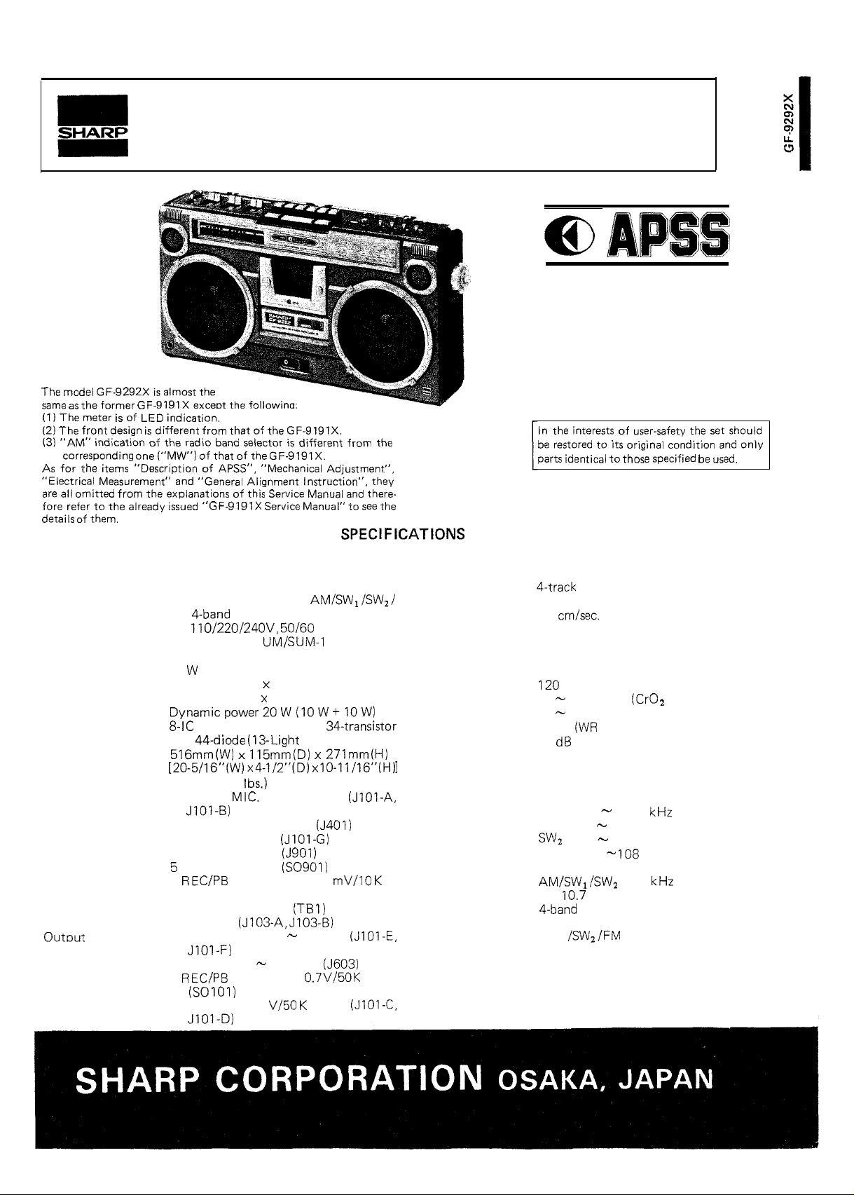
the
The meter
the
omitted
of
indication of the radio
“Description of
GF
indication.
the explanations of
from
of that of the
“General Alignment Instruction”. they
of the
selector
“Mechanical Adjustment”,
Manual” to
from the
Manual
there-
the
Manual
Auto Program Search System
MODEL
GF-9292X
the
identical to
of
to
original condition
the
only
GENERAL
Type:
Power source:
Power consumption:
Speaker:
Power output:
Semiconductors:
Dimentions:
Weight:
Input terminals:
Portable stereophonic cassette tape
recorder with built-in AM/SW,/SWZ/
FM
AC 110/220/24OV, 50/60 Hz
DC 15V (Ten
size batteries or External DC supply)
35
16 cm (Woofer) x 2,
5 cm (Tweeter)
and 44-diode (13-Light Emitting Diode)
6.5 kg (14.3
1 EXT.
2 Mixing mic. 600 ohms
3 Remote control
4 EXT. DC power
AC input power
6
7 FM EXT. antenna
8 PHONO
1 EXT. speaker, 4
2 PHONES, 8
3
radio
2
x 115mmiD) x 271mm(H)
(without batteries)
600 ohms
DIN socket, 2.5
ohms (SO1 01)
8 ohms
25 ohms
DIN socket, 0.7V/50K ohms
, R20, “D”
TAPE RECORDER SECTION
Type:
Tape:
Tape speed:
Recording system:
Erasing system:
Recording time:
Fast forward or
rewind time:
Frequency response: 40
Wow and flutter:
SIN ratio:
RADIO SECTION
Frequency
Intermediate
frequency:
Circuit system:
Antenna:
range:
Philips type compact cassette tape
4.8 cm/set.
AC bias
AC erasing
60 minutes (with C-60 tape)
sec. (with C-60 tape)
15,000 Hz
40
12,000 Hz (Normal tape)
0.09%
50
AM 525
SW,
FM
FM
AM/SW, ferrite core bar antenna
SW,
FM EXT. antenna
tape)
MS)
1,605
2.3
7.3 MHz
7.3
22 MHz
87.6
MHz
455
MHz
superheterodyne system
telescopic antenna
4 Line out, 0.7 V/50
ohms
Page 2
playback level
Battery condition/L-ch
record and playback level
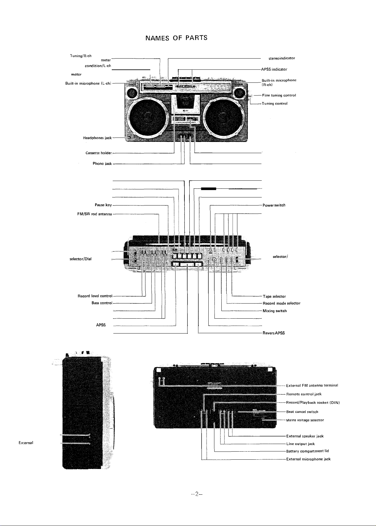
OF PARTS
FM
I
Digital tape counter
Earth terminal
Fast forward/Cue key
Meter
Playback key
Editor switch
Loudness switch
light switch
Treble control
Volume control
Forward
Stop key
key
Record key
Rewind/Review key
Eject key
Function selector
Mode selectori
FM muting switch
Fader control
Mixing microphone jack
key
Mains socket
DC power jack
Figure 1
Page 3

q
FRONT CABINET REMOVAL
Pull out the power cord plug or adaptor plug from the unit.
2. Take out the cassette tape from the cassette holder.
3. Remove eight
4. Gently pull out the front cabinet and disconnect four
q
OPERATION PANEL REMOVAL
1. Remove the front cabinet as described in front cabinet
removal.
2. Remove seven
and fader).
3. Gently lift up the operation panel from the back cabinet.
screws retaining the front cabinet.
connected to the
knobs (record level, bass, treble,
(Refer to Figures 2 and 3)
main
(Refer to Figure 3)
board
Figure 2
DIAL SCALE PLATE REMOVAL
Remove the operation panel as described in operation panel
removal.
2. Remove four
3. Gently pull out the dial scale plate from the chassis.
MECHANISM BLOCK REMOVAL
1. Remove the dial scale plate as described in dial scale plate
removal.
2. Disconnect the tip (muting) and two (2) sockets
connected to the main
P.W. board.
3. Remove four (4) screws retaining the mechanism block.
4. Gently pull out the mechanism block from the main P.W.
board holder.
q
PHONO JACK PLATE REMOVAL
1. Remove the mechanism block as described in mechanism
block removal.
2. Remove two (2) screws retaining the phono jack plate.
3. Gently pull out the phono jack plate from the back cabinet.
screws retaining the dial scale plate.
(Refer to Figure 3)
(Refer to Figure 4)
board and the motor
(Refer to Figure 5)
Figure 3
Figure 4
CHASSIS
1. Remove the phono jack plate as described in phono jack
plate removal.
2. Remove two
3. Disconnect three (3) tips (Antenna) and two (2) tips (DC
supply) connected to the main P.W. board.
4. Remove seven
5. Gently pull out the chassis (P.W.B.) from the back cabinet.
REMOVAL
knobs (tuning and fine tuning).
screws
(Refer to Figure 5)
the chassis
-3
Figure 5
Page 4

As for “Description of APSS”, “Mechanical Adjustment”,
“General Alignment Instruction” and
ment”, refer to Service Manual of Model GF-9191 X.
LEVEL AND SENSITIVITY ADJUSTMENT OF VU METER
1. Connect the V.T.V.M. across the
2. Short circuit the primary coil of the oscillation coil
to stop bias oscillation.
3. Connect the signal generator to the EXT. MIC jacks
and apply signal
4. Place the unit in RECORD mode.
5. Connect DC voltmeter between TP51 and TP52 (ground)
and adjust left channel record level control
DC voltmeter indicates I
6. Adjust the semi-variable resistor
of VU meter begins to light.
“Electrical Measure- Service Manual of Model GF-9191X.
ohm resistors
-6OdB) to the unit.
so that 5th LED
15,
A,
so that
AS for all the items except “VU-Meter Adjustment”, refer to
7. Next, change the voltage of TP51 to 0.95V by sliding the
record level control (R148), and in this time, check the 5th
LED
8. Adjust the record level controls (R147,
V.T.V.M. reads 3.5mV.
9. Adjust the semi-variable resistors (R 187,
Set the level of signal generator to
check the 4th
light.
of VU meter fails to light.
of VU meters begin to light.
(D908,
so that the
so that 4th
and this time,
of VU meters fail to
SWITCH
lower
node
nixing
oudness
mode
01
VU
08)
GENARATOR
POSITION
tape
stereo
off
off
normal
manual
JACK RECORD mode
R/P HEAD
DC VOLTME
TEF
Figure 6
Page 5

TUNING/RIGHT-“,
.
EXT. SP
Lch
LINE
so
EXT.
JIOI-G
REMOTE
,
.
.
Figure 7 ALIGNMENT POINTS
 Loading...