

st-i~~~
SERVICE
MANUAL :i
OUTSTANDING RECEPTION THE WORLD OVER
ATSM882109RCS
This Service Manual omits the descriptions about the adjustment
and block diagram of the Radio
(High
Frequency) Circuit, and for
their details, refer to the GF-54542 Service Manual (ATSM182013-
RCS)
or GF-5454 Service Manual (ATSM382047RCT).
In the interests of user-safety the set should be
restored to its original condition and only parts
identical to those specified be used.
INDEX
TO CONTENTS
SPECIFICATIONS 2
POWER
SUPPLY/VOLT&
.iiLi&i&i
’ : : : : : : : : : : : : : : : : : : : : : : : : : : : : 2
DIAL CORD STRINGING . . . . . . . . . . . . . . . . . . . . . . . . . . . . . . . . . . 2
NAMES OF CONTROLS . . . . . . . . . . . . . . . . . . . . . . . . . . . . . . . . . . . . . 3
DISASSEMBLY
.*...............................,
4
AUDIO
BLOCK
DlAikil
’ : : . . . . . . . . . . . . . . . . . . . . . . . . . . . . . . . . . . 5
CIRCUIT CONSTRUCTION . . . . . . . . . . . . . . . . . . . . . . . . . . . . . . . . . . . . 6
APPS FLOW CHART
.7,8
MECHANICAL
ADJUSiM’Efi- ’ : : : : : : : : : : : : : : : : : : : : : : :‘: : : : : : : : : :
. 9
CHECKING OF
AUDIO
(LOW FREQUENCY) CIRCUIT . . . . . . . . . . . . . . . . . . .
.lO
SCHEMATIC DIAGRAM
(l/Z), (Z/Z)
. . . . . . . . . . . . . . . . . . . . . . . . . .
11,12,15
WIRING SIDE OF PRINTED WIRING BOARD
(l/Z), (Z/Z)
. . . . . . . . . . , . . . . .
13,14,16
SCHEMATIC DIAGRAM AND WIRING SIDE OF PRINTED WIRING BOARD AT
POWER SUPPLY SECTION OF GF-500 . . . . . . . . . . . . . . . . . . . . . . . . . . . _
.17
AC POWER SUPPLY CORD . . . . . . . . . . . . . . . . . . . . . . . . . . . . . . . . . . .
.I7
NOTES ON SCHEMATIC DIAGRAM
18
DECK 1 MECHANISM EXPLODED
Vii : : : : : : : : : : : : : : : : : : : : : : : : : : : : :
19
DECK 2 MECHANISM EXPLODED VIEW . . . . . . . . . . . . . . . . . . . . . . . . . . .
.20
CABINET EXPLODED VIEW . . . . . . . . . . . . . . . . . . . . . . . . . . . . . . . .
21,22
REPLACEMENT PARTS LIST . . . . . . . . . . . . . . . . . . . . . . . . . . . . .
23%
Back
SHARP CORPORATION
SHARP
ELECTRONICS
CORPORATION
1.
GENERAL
Power source:
(G
F-500)
(G
F-5002)
Speakers: Woofer;
Tweeter;
Output power:
(G
F-500)
(GF-5002)
Semiconductors:
(G
F-500)
(G
F-5002)
FOR A COMPLETE DESCRIPTION OF THE OPERATION OF THIS
UNIT, PLEASE REFER TO THE
OPERAT.lON
MANUAL.
SPECIFICATIONS
AC 110 -
12Ol220 - 24OV, 50/60Hz
DC 12V (Ten “D” Size batteries or
external DC supply)
AC 110 -
127/220 - 24OV, 50/60Hz
DC
12V (UM/SUM-1,
R-20, HP-Z, or
battery x 8, “D” or external DC
supply)
12cm
(4-3/4”) x
2
Ceramic type x 2
2.3 Watts per channel, minimum RMS,
at 3 ohms, from
100Hz
to
20kHz
with
no more than 10% Total harmonic dis-
tortion.
PMPO; 25W (12.5W + 12.5W)
(AC Operation)
MPO;
2ow (low
+
low)
(AC Operation)
RMS;
IOW
(5W
+ 5W)
(DC Operation, 10% Distortion)
9-IC’s
(Integrated Circuits) + 6 Aux. IC’s
2 Transistors + 21 Aux. Transistors
58-Diodes
1 O-LED’s
15-IC’S
23 Transistors
58-Diodes
IO-LED’s
Dimensions: Width; 582mm
(22-7/g”)
Depth; 125mm
(4-I 5/16”)
Height;
202mm (7-15/16”)
Weight (without batteries):
5.lkg
(11.3
Ibs.)
TAPE RECORDER/PLAYER
Tape: Philips-type compact cassette tape
Frequency response:
40Hz
to
16,OOOHz
(Metal tape)
S/N ratio: Deck 2
50dB (Normal tape recording)
Deck 1 55dB (Playback)
Wow and flutter: 0.06% (WRMS)
Input impedance: External Mic; 600 ohms
Phone/Line
in; 50K
ohms/20K
ohms
Output impedance:
Headphones;
8 ohms to 32 ohms
External speaker; 3 ohms to 8 ohms
Line out;
0.55Vl50K
ohms
RADIO
Frequency range:
AM; 525kHz to
1,605kHz
SW1 ; 2.3MHz
to
7.3MHz
SW2 ; 7.3MHz
to
22MHz
FM;
87.6MHz
to
108MHz
Specifications for this model are
orior
notice.
POWER
SUPPLY
The GF-500Z Unit will operate on an AC power supply of The GF-500 Unit will operate on an AC power supply of 11
O-
110 -
127 Volts, or 220
-
240 Volts of
50Hz
or
60Hz.
For 120 Volts, or 220
-
240 Volts of 50Hz or
60Hz.
For portable
portable use it
will
operate on its internal batteries, or from an
use it will operate on its internal batteries, or from an external
external 15 Volts DC supply (with an adaptor).
15 Volts DC supply (with an adaptor).
VOLTAGE SELECTION
Before operating the unit on mains, check the preset voltage.
If the voltage is different from your local
vo!tage,
adjust the
voltage as follows: Slide the AC power supply socket cover by
a little loosing screw to the visible indication of the side
OF
your local
voltage.
1.
2.
DIAL
CORD
STRINGING
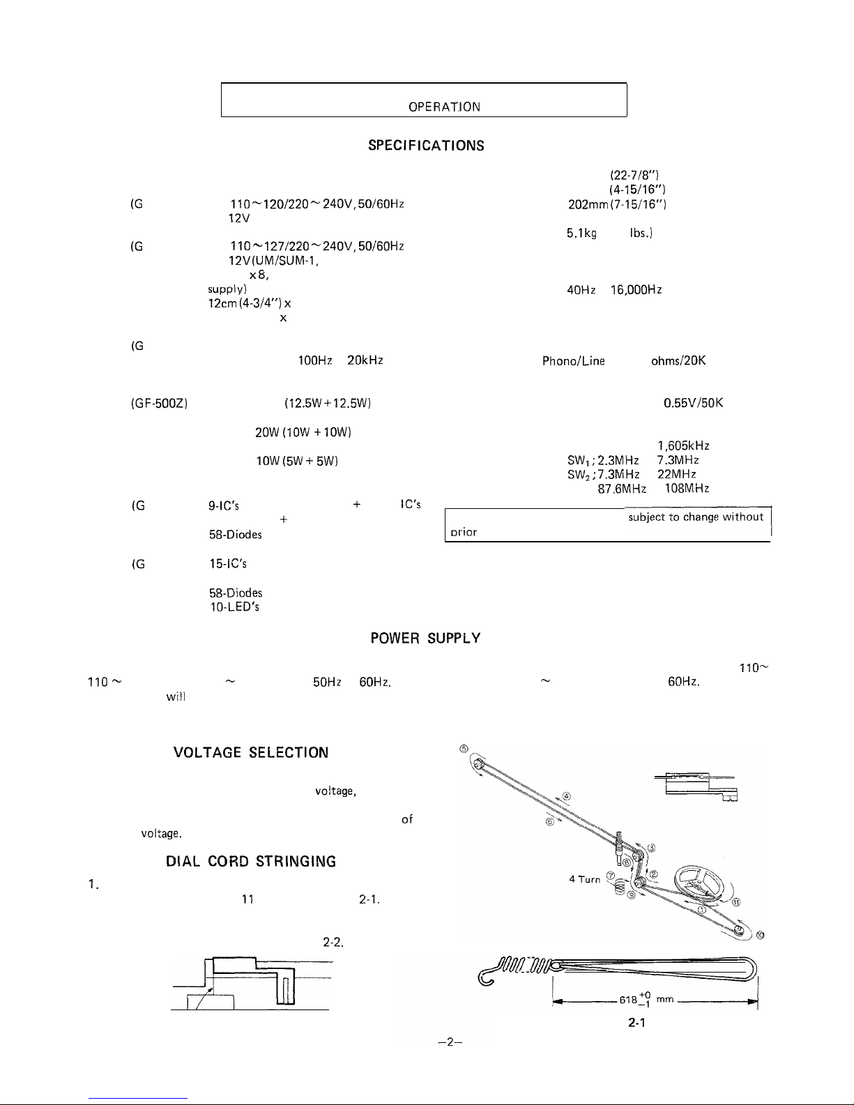
Turn the drum fully clockwise, and set the cord in the
numerical order from 1 to 11 as shown in Figure
2-I.
Turn the tuning control knob driving shaft fully clockwise,
and adjust the dial pointer to come into “Marking-off Line”
position of the dial scale plate. See Figure
2-2.
Marking-off Line
Figure 2-2
Figure
2-I
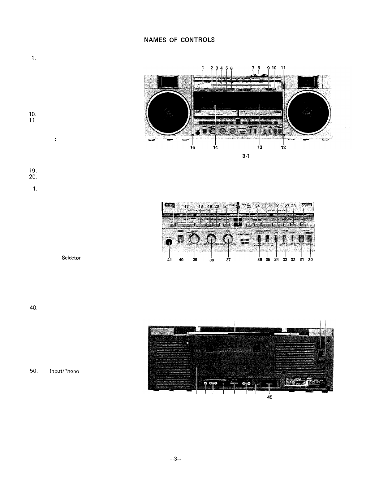
1.
Level Meter
2. Power On/Battery Indicator
3. APPS Indicator
4. APPS End-Pause indicator
5. Dubbing Indicator
6. FM Stereo Indicator
7. Tuning Control
8. Fine Tuning Control
9. Deck 2: Digital Tape Counter
IO.
Tape Counter Reset Button
11. Band Selector
12. Built-in Microphone (Right Channel)
13. Deck 2: Cassette Compartment
14. Deck 1 : Cassette Compartment
15. Built-in Microphone (Left Channel)
16. Deck 1: Eject Button
17. Deck 1: Play Button
18. Deck 1: Stop Button
19. Deck 1: Rewind/Reverse APSS Button
29.
Deck 1: Fast Forward/Forward APSS
Button
2 1.Deck 1: Pause Button
22. Dubbing Start Button
23. Deck 2: Eject Button
24. Deck 2: Record Button
25. Deck 2: Play Button
26. Deck 2: Stop Button
27. Deck 2: Rewind/Review Button
28. Deck 2: Fast Forward/Cue Button
29. Deck 2: Pause Button
30. Power Switch
31. Function Selector Switch
32.
FM Mode
Selactor
33. Deck 2: Tape Selector Switch
34. Deck 2: Record Muting Switch
35. Dubbing Switch
36. Dubbing Speed Selector Switch
37. Tone Control
38. Balance Control
39. Volume Control
49.
APPS Set/Clear Switch
41. Headphones Socket
42. FM/SW Telescopic Rod Antenna
43. External DC Power Supply Socket
44.
AC Power Supply Socket
45. External Speaker Sockets
46. Beat Cancel Switch
47. Line Output Sockets
48. External Microphone Sockets
49. Input Selector Switch
50.
Line
Ihput/Phono
Input Sockets
51. Earth Terminal
52. Battery Compartment
NAMES OF
CONTROLS
Figure
3-1
Figure 3-2
42
4344
52 51 50 49 48
47 46
45
Figure 3-3
-..3-
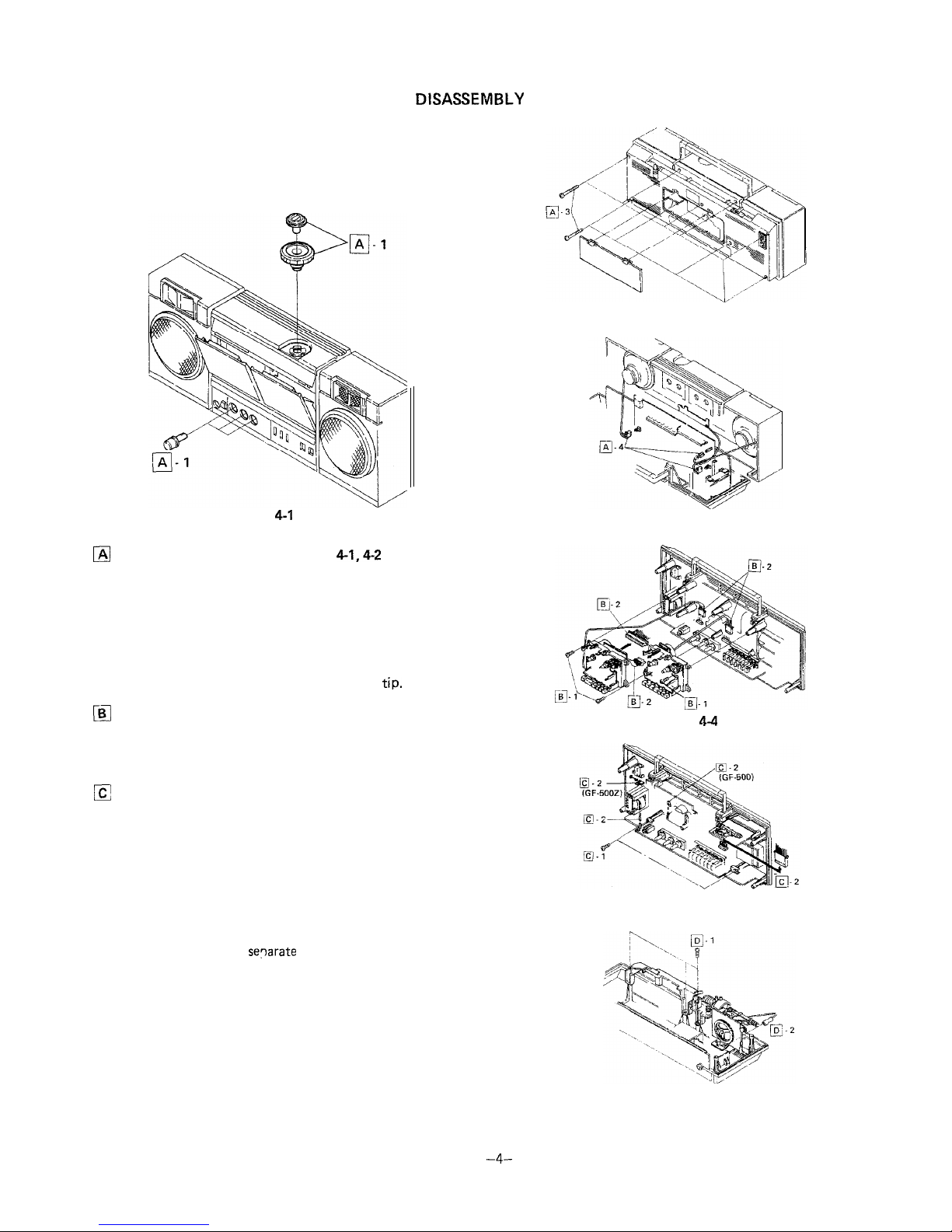
DISASSEMBLY
Caution:
Prior to the disassembly, be sure to draw the AC power supply
lead plug from the AC power supply socket of the unit and to
unload the cassette compartment with a cassette tape and the
battery compartment with batteries.
Figure 4-1
m
Removal of Front Cabinet (See Figs.
4-1,4-2
and 4-3)
1. Pull out one tuning control knob one fine tuning control
knob and three control knobs (volume, balance and tone),
all at the front surface of the unit.
2. Push the eject button to open the cassette compartment.
3. Remove nine screws from the front cabinet and back
cabinet: one screw of the nine is found in the battery
compartment.
4. Disconnect two speaker sockets and one earth
tip.
a
Removal of Mechanism Block (See Fig. 4-4)
1. Remove three screws from the mechanism block and the
drive belt from the tape counter.
2. Disconnect four sockets and detach the mechanism block.
a
Removal of Main P.W.B. (See Fig. 4-5)
1. Remove two screws from the main P.W.B. and pull the
P.W.B. forwards.
2. Disconnect two sockets and pull one tip out, then detach
the P.W.B.
3. If necessary, it is recommended to detach the indicator
P.W.B. from the tuner frame.
q
Removal of Tuner Frame (See Fig. 4-6)
1. Remove three screws from the tuner frame.
2. Pull out one tip and
separate
the tuner from the back
cabinet.
Figure 4-2
Figure 4-3
Figure
44
Figure 4-5
Figure 4-6
-4-
zl-
II I
a
5
"
I I
I
--+-t--lI I
I
I I I
I
--
i
------.---_------
_____
----T
.-------
j&
211
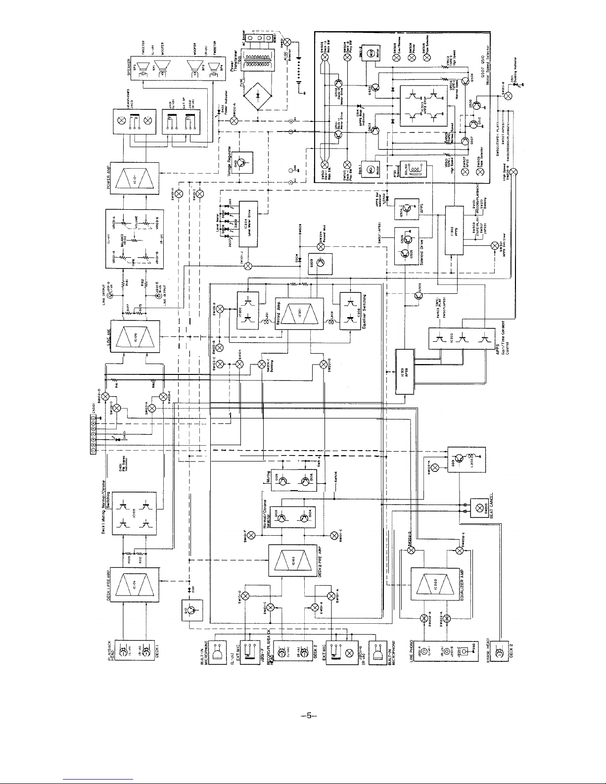
Figure 5 BLOCK DIAGRAM
-5-
-.--...-
---.---..--.-
CIHCU17
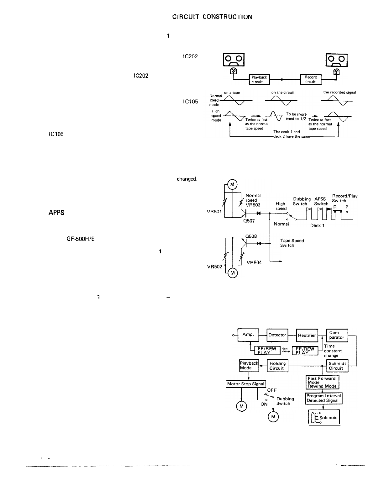
It is possible to select either normal tape speed or high tape
speed when you perform dubbing from the deck 1 to the deck
2 and the high speed is twice as fast as the normal speed.
l
Normal speed/high speed record selector circuit
Being provided at the deck 2, the integrated circuit
IC202
works to select the normal speed mode or the high speed
mode: the frequency at the high speed is two times higher
than that at the normal speed. The
IC202
also works to detect
whether a normal tape or a metal tape has been loaded in the
unit.
l
Normal speed/high speed playback selector circuit
Being provided at the deck 1, the integrated circuit
ICI05
works to select the normal speed mode or the high speed
mode: the frequency at the high speed is two times higher
than that at the normal speed. Here is also given proper
equalization for the signals of both speed modes. Further the
IC105
changes its constant according to whether a normal tape
or a metal tape has been loaded in the unit.
l
Normal speed/high speed selector circuit
Change of the motor’s rotational speed results in a changeover
between the tape normal speed and high speed modes. The
electronic switch is used to act on the motor control circuits
of the deck 1 and deck 2 at a time as their speeds are
changed.
Fig. 6-2 shows how the circuit works to get the unit in the
high speed mode, whose expression is made with use of the
mechanical switch instead of the electronic switch.
APPS
(Automatic Program Pause System)
The existing APSS, as you know, is to automatically detect an
end of the program when the unit is in fast forward or rewind
mode and then to return it to play mode. The APPS employed
for the GF-SOOH/E is something new which is based on the
same ideas as with such APSS, and it is activated not only
when the unit is in play mode (at the deck 1 only) but also
when it is in dubbing mode (from the deck 1 to the deck 2).
In the dubbing mode (either at normal speed or at high speed),
as soon as an end of the program is detected by the APSS in
the deck 1, the APPS works to stop the motor circuits of both
decks 1 and 2 simultaneously -that is, motions of the deck 1
and deck 2 are stopped just at a time.
Therefore, the deck 1 has two automatic controls - APSS and
APPS, that is, it is controlled by the APSS when it is in play
mode (with the deck 2 in stop mode) and by the APPS when it
is in dubbing mode.
The two controls APSS and APPS are differentiated by the
following:
l
Difference in gain and frequency characteristic between
APSS and APPS.
l
Difference in program detect time between APSS and
APPS.
These differences are due to that the tape speed is different
according to whether the unit is in play mode or dubbing
mode, and according to these, the electronic switch selects the
APSS or APPS to get it in action.
CUNS~I KUCTION
Deck 1
Dubbing
Deck 2
Wave length
Wave length
Wave length of
signal wave length.
Figure 6-l
Deck 1 Motor
High
Speed
VR501
Q507
Motor Selector
Transistor
Deck 2
Speed
Play Switch
‘k”
Normal
High
Speed
Speed
L
Deck 1 Playback Equalizer Selector
VR504
VR502
Deck 2 Record Equalizer Selector
M
Deck 2 Motor
Figure 6-2
Input
signal
Deck 1 Motor
Deck 2 Motor
Figure 6-3
-6-
/ fleolenoid 1
/ .
__-L-__Illl.
___ ---.-.
.._ _ .~_
,_.- . .._- . -..~. .I __., --~ .--- -- .--1----_--
- ._.._
_I--
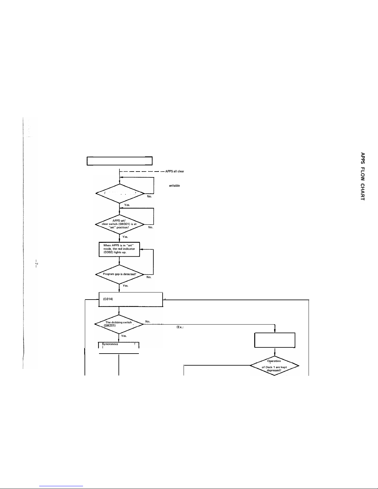
APPS Flow Chart
I
/-- - - - - - -APPSallclear
APPS not settable
Deck 1 is in play mode?
The motor stops and the yellow indicator
-
(D314)
lights up. The red indicator is still
-
lit at the time.
(SW201)
is turned on?
Syncronous operation
of
Deck 1 and Deck 2 is
(EL:
With Deck 2 in stop or play mode, or
with the dubbing switch turned off)
I
The motor of Deck 1 gets
in a stop: Deck 2 alone can
be operated.
+
I
stopped.
I
No.
buttons (for play mode)
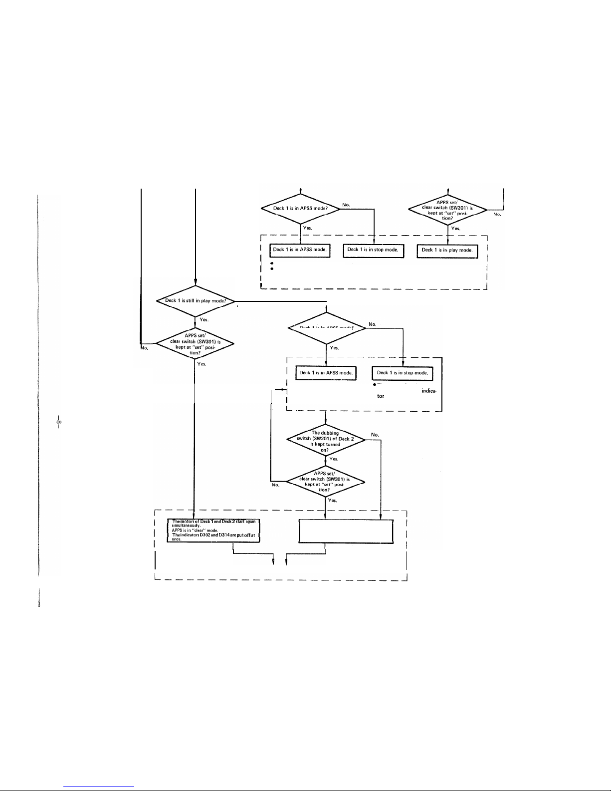
0 The motor of Deck 1 starts again.
0
APSS set/clear switch is at “set”
position. (The indicators D302
and D314 are both put off).
I
L-e--
----
------------
Deck 1 is in APSS mode or in stop mode.
No.
I
Deck1is in APSS mode?
l
APPS set/clear switch is at
@
The motor of Deck 2 is kept
--I
“set” position.
in stop. (The yellow indica-
1
l
The motor of Deck 1 starts again.
tar
D314 keeps on lighting.)
(The red indicator D302 is put off.)
The
motors of
Deck 1 and Deck 2
start
again
The motor of Deck 1 starts again.
The indicators
D302
and
D314
are
put
off at
The yellow indicator D314 is put off.
bl--
APPS all clear.
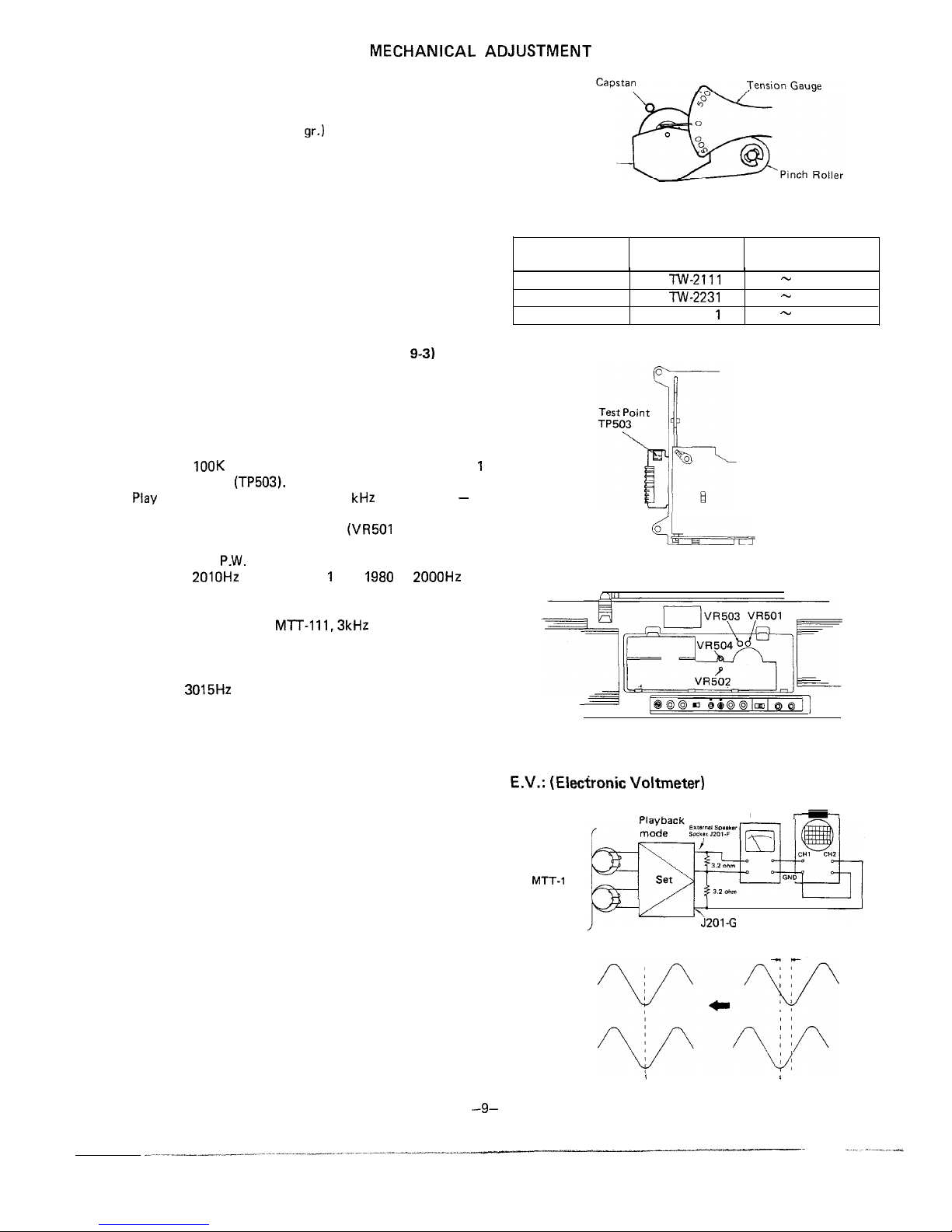
MECHANICAL ADJUSTMENT
PINCH ROLLER PRESSURE CHECK
1. Place the unit in PLAY mode.
2. Push the pinch roller, at the point shown in Fig. 9-1, by
using a tension gauge (500
gr.)
so that it will come off the
capstan. Then, release the tension slowly until the pinch
roller hits the capstan again (i.e., the pinch roller is about to
rotate again). Then check the tension gauge is reading
350 gr. to 420 gr.
3. If the reading is outside the range of 350 gr. to 420 gr.
replace the pressure spring of the pinch roller.
TORQUE CHECK AT PLAY, FAST FORWARD AND
REWIND MODES
Put a torque meter cassette in the cassette compartment of the
set, and see that the measured torque in each mode is normal
as follows:
TAPE SPEED ADJUSTMENT (See Figs. 9-2 and
9-3)
Note:
The high speed operation has priority over the normal speed
operation, and so try to do the adjustment for the former first
and then for the latter.
For High Speed Operation
1. Connect a wow/flutter meter to the Line Output socket
across a
100K
ohm resistor, and shortcircuit the deck
1
control terminal
(TP503).
2.
Play
a test tape (TEAC, MTT-118, 1
kHz
prerecorded) - at
its middle part but not at its start or end point.
3. Adjust the semi-variable resistors
(VR501
for the deck 1
and VR502 for the deak 2) located on the deck 1 and deck
2 mechanism
P.W.
Boards, so that the output frequency is
1990 to
2010Hz
for the deck 1 and
1980
to
2000Hz
for
the deck 2.
For Normal Speed Operation:
1. Play a test tape (TEAC,
Ml-T-1 11,3kHz
prerecorded).
2. Adjust the semi-variable resistors (VR503 for the deck 1
and VR504 for the deck 2) located on the deck 1 and deck
2 mechanism P.W. Boards, so that the output frequency is
2985 to
3015Hz
on the wow/flutter meter for both decks 1
and 2.
RECORD/PLAYBACK HEAD AZIMUTH ADJUSTMENT
1. Make Connection of instruments as shown in Fig. 9-4.
2. Set the Dubbing switch SW201 to the off position and Tape
Selector switch SW105 to Normal position.
3. Adjust the head azimuth adjusting screw so that sine
waveform attains the maximum and the same phase in right
and left.
4. Even without using the oscilloscope, also adjust the head
azimuth adjusting screw so that outputs of both the right
and left channels attain the maximum and the same phase
in right and left.
Note:
For some heads, there may be a phase difference between
right and left channels when the output is made maximum.
In this case, adjust the head azimuth so that such phase
difference will be as small as possible while keeping the
output still maximum.
Pinch Roller
Pressure Spring
Figure 9-l
Mode
Torque meter
cassette
Measured torque
Playback TW-2111
Fast-forward TW-2231
Rewind TW-223
1
35-60 gram-cm
90-135 gram-cm
90-135 gram-cm
<--
Figure 9-2
Figure 9-3
E.V.:
(Elecfronic Voltmeter)
Test Tape
MT-r-1
14
Oscilloscope
E.V.
h’
J201 -G
as small as possible
/
I
Figure 9-4
-9-
 Loading...