

Page 1
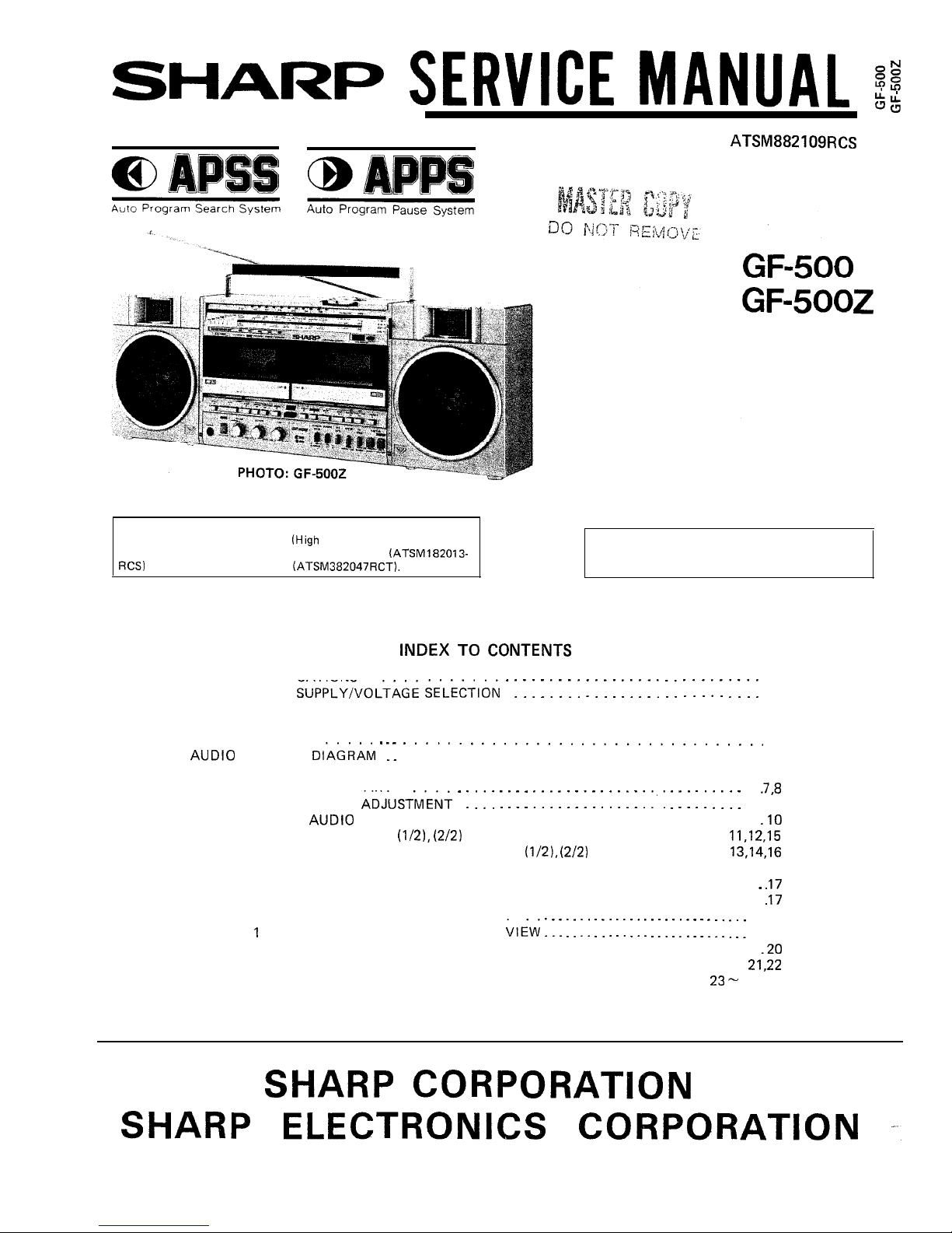
OUTSTANDING RECEPTION THE WORLD OVER
This Service Manual omits the descriptions about the adjustment
and block diagram of the Radio
Frequency) Circuit, and for
their details, refer to the GF-54542 Service Manual (ATSM182013-
or GF-5454 Service Manual (ATSM382047RCT).
In the interests of user-safety the set should be
restored to its original condition and only parts
identical to those specified be used.
TO CONTENTS
SPECIFICATIONS 2
POWER
2
DIAL CORD STRINGING . . . . . . . . . . . . . . . . . . . . . . . . . . . . . . . . . . 2
NAMES OF CONTROLS . . . . . . . . . . . . . . . . . . . . . . . . . . . . . . . . . . . . . 3
DISASSEMBLY
4
BLOCK
. . . . . . . . . . . . . . . . . . . . . . . . . . . . . . . . . . 5
CIRCUIT CONSTRUCTION . . . . . . . . . . . . . . . . . . . . . . . . . . . . . . . . . . . . 6
APPS FLOW CHART
MECHANICAL
. 9
CHECKING OF
(LOW FREQUENCY) CIRCUIT . . . . . . . . . . . . . . . . . . .
SCHEMATIC DIAGRAM
. . . . . . . . . . . . . . . . . . . . . . . . . .
WIRING SIDE OF PRINTED WIRING BOARD
. . . . . . . . . . , . . . . .
SCHEMATIC DIAGRAM AND WIRING SIDE OF PRINTED WIRING BOARD AT
POWER SUPPLY SECTION OF GF-500 . . . . . . . . . . . . . . . . . . . . . . . . . . .
AC POWER SUPPLY CORD . . . . . . . . . . . . . . . . . . . . . . . . . . . . . . . . . . .
NOTES ON SCHEMATIC DIAGRAM
18
DECK
MECHANISM EXPLODED
19
DECK 2 MECHANISM EXPLODED VIEW . . . . . . . . . . . . . . . . . . . . . . . . . . .
CABINET EXPLODED VIEW . . . . . . . . . . . . . . . . . . . . . . . . . . . . . . . .
REPLACEMENT PARTS LIST . . . . . . . . . . . . . . . . . . . . . . . . . . . . .
Back
Page 2
GENERAL
Power source:
F-500)
F-5002)
Speakers: Woofer;
Tweeter;
Output power:
F-500)
Semiconductors:
F-500)
F-5002)
FOR A COMPLETE DESCRIPTION OF THE OPERATION OF THIS
UNIT, PLEASE REFER TO THE
MANUAL.
AC 110
DC 12V (Ten “D” Size batteries or
external DC supply)
AC 110
DC
R-20, HP-Z, or
battery
8, “D” or external DC
2
Ceramic type
2
2.3 Watts per channel, minimum RMS,
at 3 ohms, from
to
with
no more than 10% Total harmonic dis-
tortion.
PMPO; 25W (12.5W + 12.5W)
(AC Operation)
MPO;
+
(AC Operation)
RMS;
+ 5W)
(DC Operation, 10% Distortion)
(Integrated Circuits) + 6 Aux. IC’s
2 Transistors + 21 Aux. Transistors
1 O-LED’s
23 Transistors
Dimensions: Width; 582mm
Depth; 125mm
Height;
Weight (without batteries):
(11.3
TAPE RECORDER/PLAYER
Tape: Philips-type compact cassette tape
Frequency response:
to
(Metal tape)
S/N ratio: Deck 2
50dB (Normal tape recording)
Deck 1 55dB (Playback)
Wow and flutter: 0.06% (WRMS)
Input impedance: External Mic; 600 ohms
in; 50K
ohms
Output impedance:
Headphones;
8 ohms to 32 ohms
External speaker; 3 ohms to 8 ohms
Line out;
ohms
RADIO
Frequency range:
AM; 525kHz to
to
to
FM;
to
Specifications for this model are
notice.
SUPPLY
The GF-500Z Unit will operate on an AC power supply of The GF-500 Unit will operate on an AC power supply of
127 Volts, or 220
240 Volts of
or
For 120 Volts, or 220
240 Volts of 50Hz or
For portable
portable use it
operate on its internal batteries, or from an
use it will operate on its internal batteries, or from an external
external 15 Volts DC supply (with an adaptor).
15 Volts DC supply (with an adaptor).
Before operating the unit on mains, check the preset voltage.
If the voltage is different from your local
adjust the
voltage as follows: Slide the AC power supply socket cover by
a little loosing screw to the visible indication of the side
your local
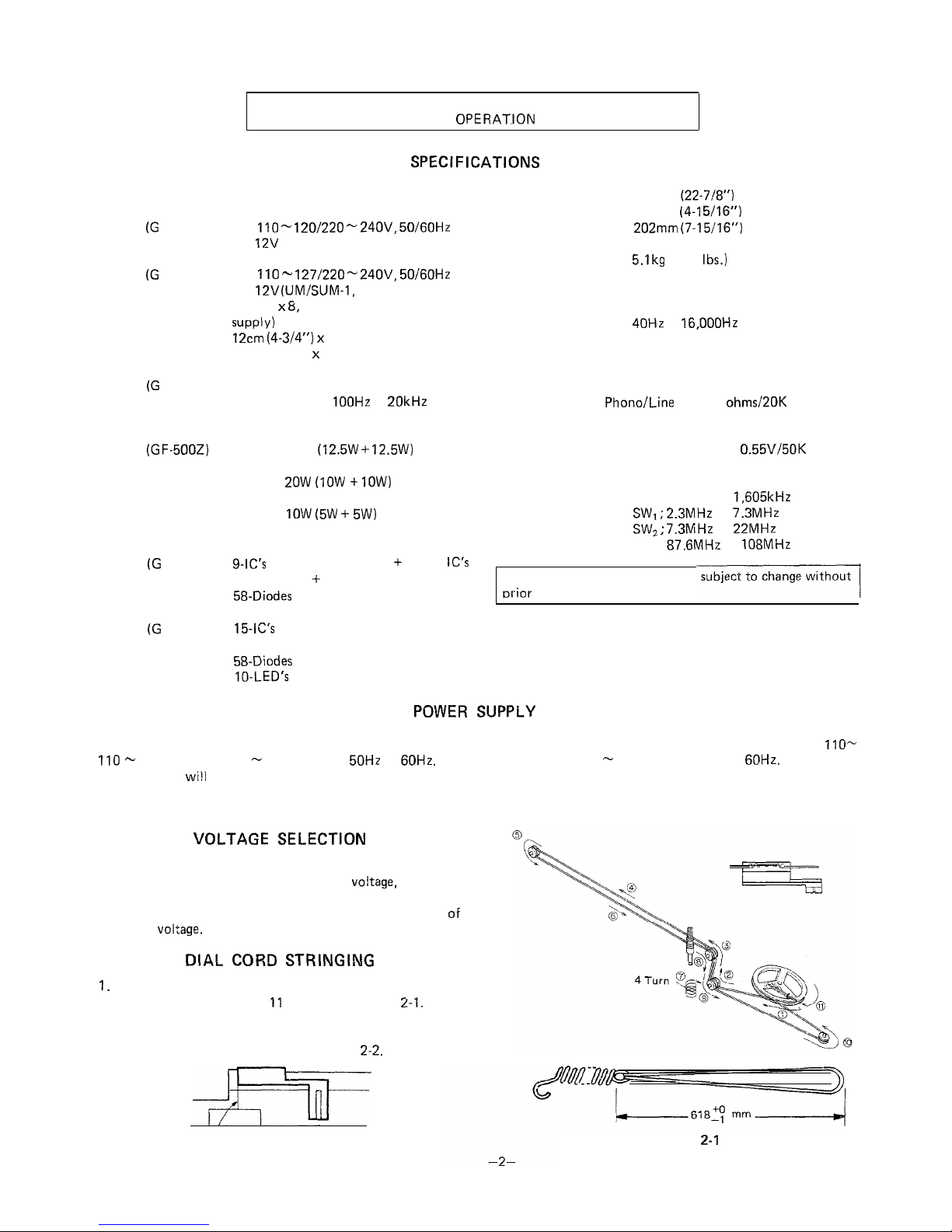
2.
CORD
Turn the drum fully clockwise, and set the cord in the
numerical order from 1 to
as shown in Figure
Turn the tuning control knob driving shaft fully clockwise,
and adjust the dial pointer to come into “Marking-off Line”
position of the dial scale plate. See Figure
Marking-off Line
Figure 2-2
Figure
Page 3
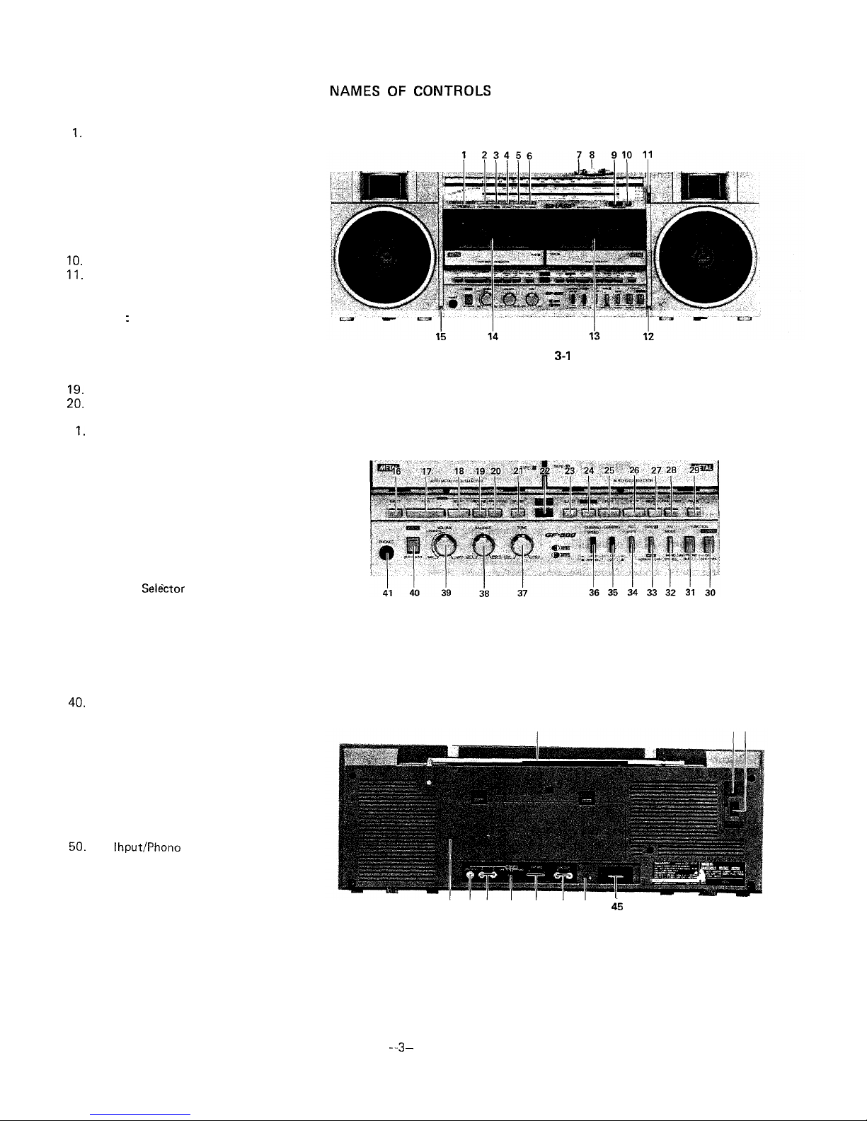
Level Meter
2. Power On/Battery Indicator
3. APPS Indicator
4. APPS End-Pause indicator
5. Dubbing Indicator
6. FM Stereo Indicator
7. Tuning Control
8. Fine Tuning Control
9. Deck 2: Digital Tape Counter
Tape Counter Reset Button
12. Built-in Microphone (Right Channel)
13. Deck 2: Cassette Compartment
14. Deck 1
Cassette Compartment
15. Built-in Microphone (Left Channel)
16. Deck 1: Eject Button
17. Deck 1: Play Button
18. Deck 1: Stop Button
Deck 1: Fast Forward/Forward APSS
Button
2
Deck 1: Pause Button
22. Dubbing Start Button
23. Deck 2: Eject Button
24. Deck 2: Record Button
25. Deck 2: Play Button
26. Deck 2: Stop Button
27. Deck 2: Rewind/Review Button
28. Deck 2: Fast Forward/Cue Button
29. Deck 2: Pause Button
30. Power Switch
31. Function Selector Switch
32.
FM Mode
33. Deck 2: Tape Selector Switch
34. Deck 2: Record Muting Switch
35. Dubbing Switch
36. Dubbing Speed Selector Switch
37. Tone Control
38. Balance Control
39. Volume Control
APPS Set/Clear Switch
41. Headphones Socket
42. FM/SW Telescopic Rod Antenna
43. External DC Power Supply Socket
44.
AC Power Supply Socket
45. External Speaker Sockets
46. Beat Cancel Switch
47. Line Output Sockets
48. External Microphone Sockets
49. Input Selector Switch
Line
Input Sockets
51. Earth Terminal
52. Battery Compartment
CONTROLS
Figure
Figure 3-2
42
4344
52 51 50 49 48
47 46
Figure 3-3
Page 4
Caution:
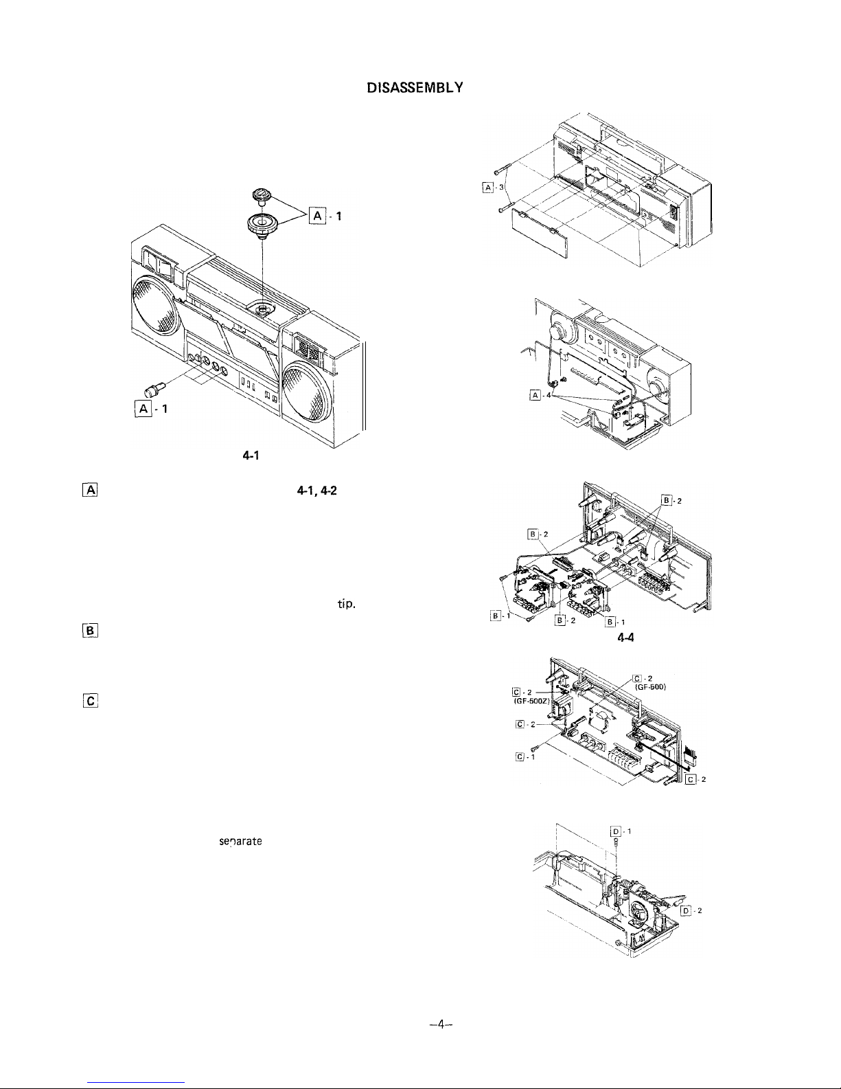
Prior to the disassembly, be sure to draw the AC power supply
lead plug from the AC power supply socket of the unit and to
unload the cassette compartment with a cassette tape and the
battery compartment with batteries.
Figure 4-1
Removal of Front Cabinet (See Figs.
and 4-3)
1. Pull out one tuning control knob one fine tuning control
knob and three control knobs (volume, balance and tone),
all at the front surface of the unit.
2. Push the eject button to open the cassette compartment.
3. Remove nine screws from the front cabinet and back
cabinet: one screw of the nine is found in the battery
compartment.
4. Disconnect two speaker sockets and one earth
Removal of Mechanism Block (See Fig. 4-4)
1. Remove three screws from the mechanism block and the
drive belt from the tape counter.
2. Disconnect four sockets and detach the mechanism block.
Removal of Main P.W.B. (See Fig. 4-5)
1. Remove two screws from the main P.W.B. and pull the
P.W.B. forwards.
2. Disconnect two sockets and pull one tip out, then detach
the P.W.B.
3. If necessary, it is recommended to detach the indicator
P.W.B. from the tuner frame.
q
Removal of Tuner Frame (See Fig. 4-6)
1. Remove three screws from the tuner frame.
2. Pull out one tip and
the tuner from the back
cabinet.
Figure 4-2
Figure 4-3
Figure
Figure 4-5
Figure 4-6
Page 5
I
a
I
I
I
I
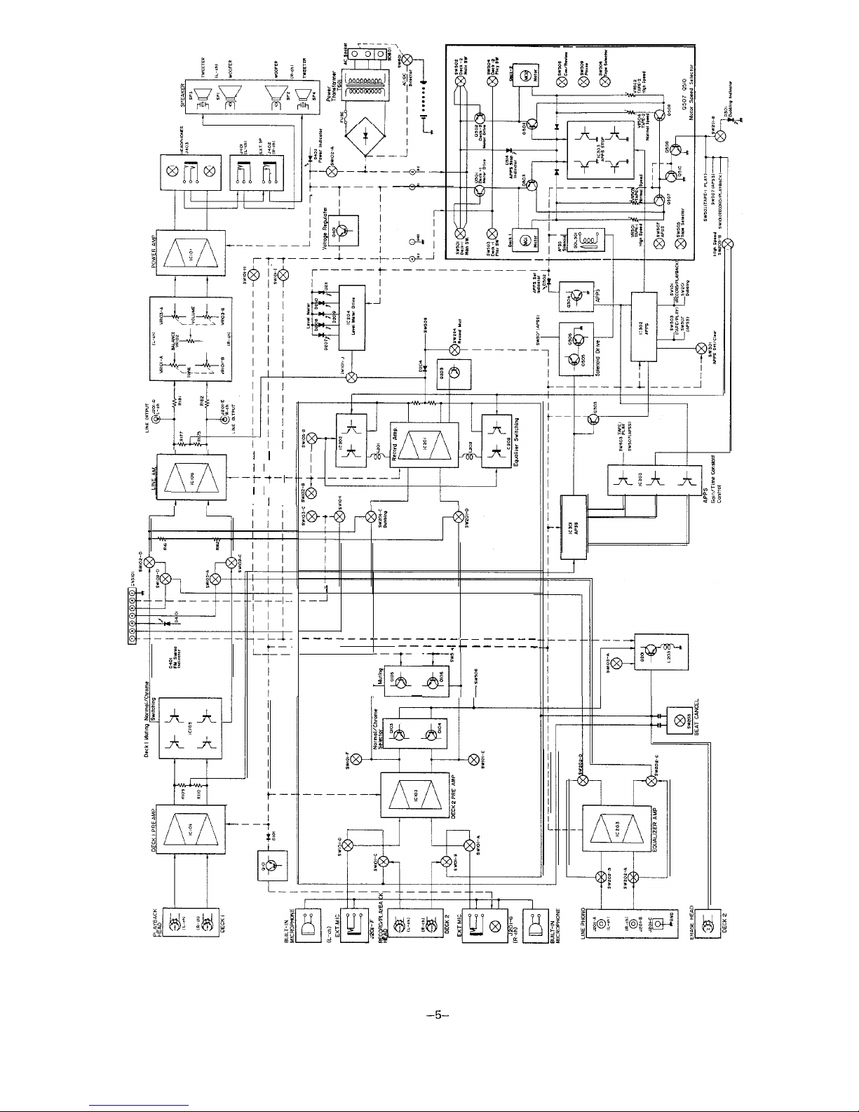
Figure 5 BLOCK DIAGRAM
Page 6
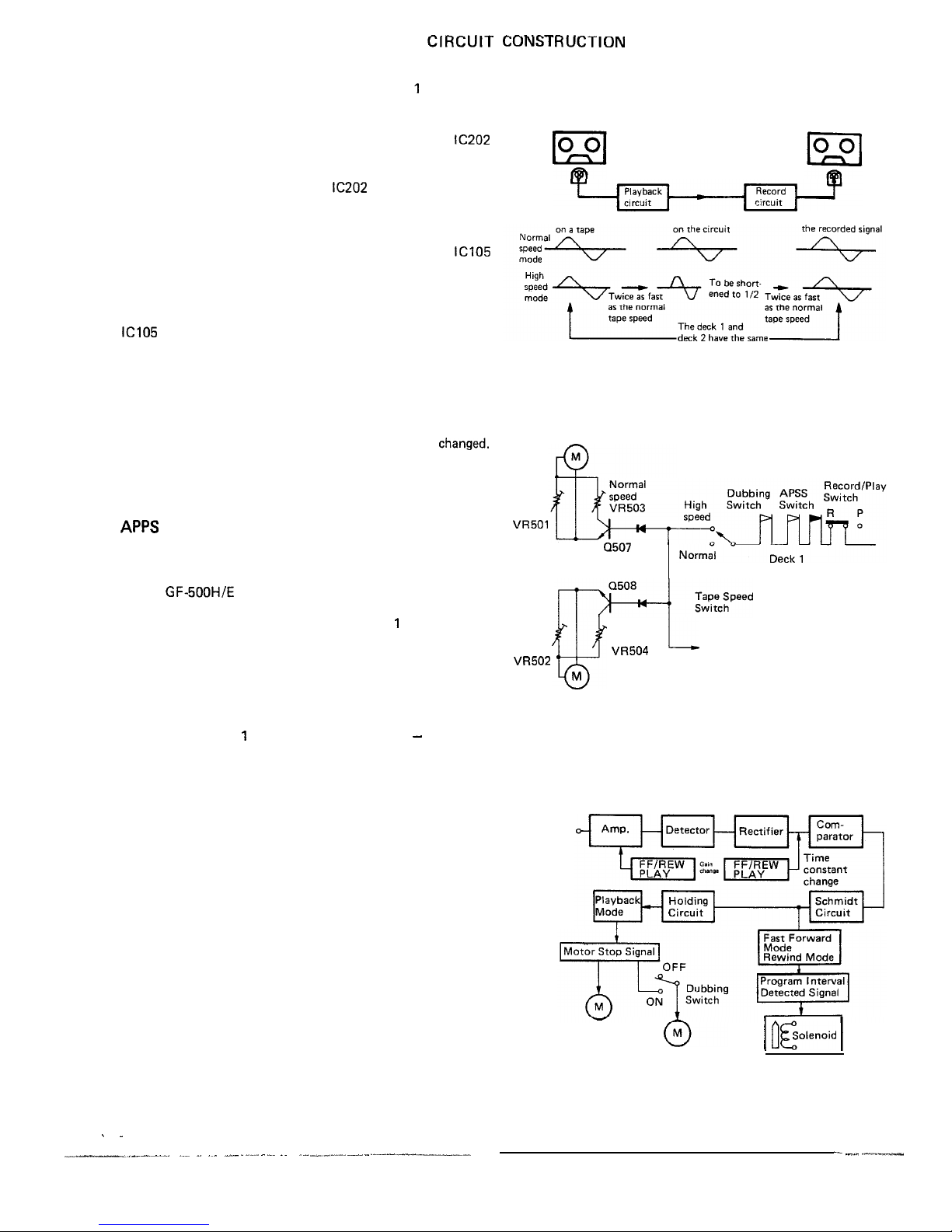
It is possible to select either normal tape speed or high tape
speed when you perform dubbing from the deck
to the deck
2 and the high speed is twice as fast as the normal speed.
l
Normal speed/high speed record selector circuit
Being provided at the deck 2, the integrated circuit
works to select the normal speed mode or the high speed
mode: the frequency at the high speed is two times higher
than that at the normal speed. The
also works to detect
whether a normal tape or a metal tape has been loaded in the
unit.
l
Normal speed/high speed playback selector circuit
Being provided at the deck 1, the integrated circuit
works to select the normal speed mode or the high speed
mode: the frequency at the high speed is two times higher
than that at the normal speed. Here is also given proper
equalization for the signals of both speed modes. Further the
changes its constant according to whether a normal tape
or a metal tape has been loaded in the unit.
l
Normal speed/high speed selector circuit
Change of the motor’s rotational speed results in a changeover
between the tape normal speed and high speed modes. The
electronic switch is used to act on the motor control circuits
of the deck 1 and deck 2 at a time as their speeds are
Fig. 6-2 shows how the circuit works to get the unit in the
high speed mode, whose expression is made with use of the
mechanical switch instead of the electronic switch.
(Automatic Program Pause System)
The existing APSS, as you know, is to automatically detect an
end of the program when the unit is in fast forward or rewind
mode and then to return it to play mode. The APPS employed
for the GF-SOOH/E is something new which is based on the
same ideas as with such APSS, and it is activated not only
when the unit is in play mode (at the deck
only) but also
when it is in dubbing mode (from the deck 1 to the deck 2).
In the dubbing mode (either at normal speed or at high speed),
as soon as an end of the program is detected by the APSS in
the deck 1, the APPS works to stop the motor circuits of both
decks 1 and 2 simultaneously -that is, motions of the deck 1
and deck 2 are stopped just at a time.
Therefore, the deck
has two automatic controls
APSS and
APPS, that is, it is controlled by the APSS when it is in play
mode (with the deck 2 in stop mode) and by the APPS when it
is in dubbing mode.
The two controls APSS and APPS are differentiated by the
following:
l
Difference in gain and frequency characteristic between
APSS and APPS.
l
Difference in program detect time between APSS and
APPS.
These differences are due to that the tape speed is different
according to whether the unit is in play mode or dubbing
mode, and according to these, the electronic switch selects the
APSS or APPS to get it in action.
Deck 1
Dubbing
Deck 2
Wave length
Wave length
Wave length of
signal wave length.
Figure 6-l
Deck 1 Motor
High
Speed
Motor Selector
Transistor
Deck 2
Speed
Play Switch
Normal
High
Speed
Speed
Deck 1 Playback Equalizer Selector
Deck 2 Record Equalizer Selector
Deck 2 Motor
Figure 6-2
Input
signal
Deck 1 Motor
Deck 2 Motor
Figure 6-3
-6-
Page 7
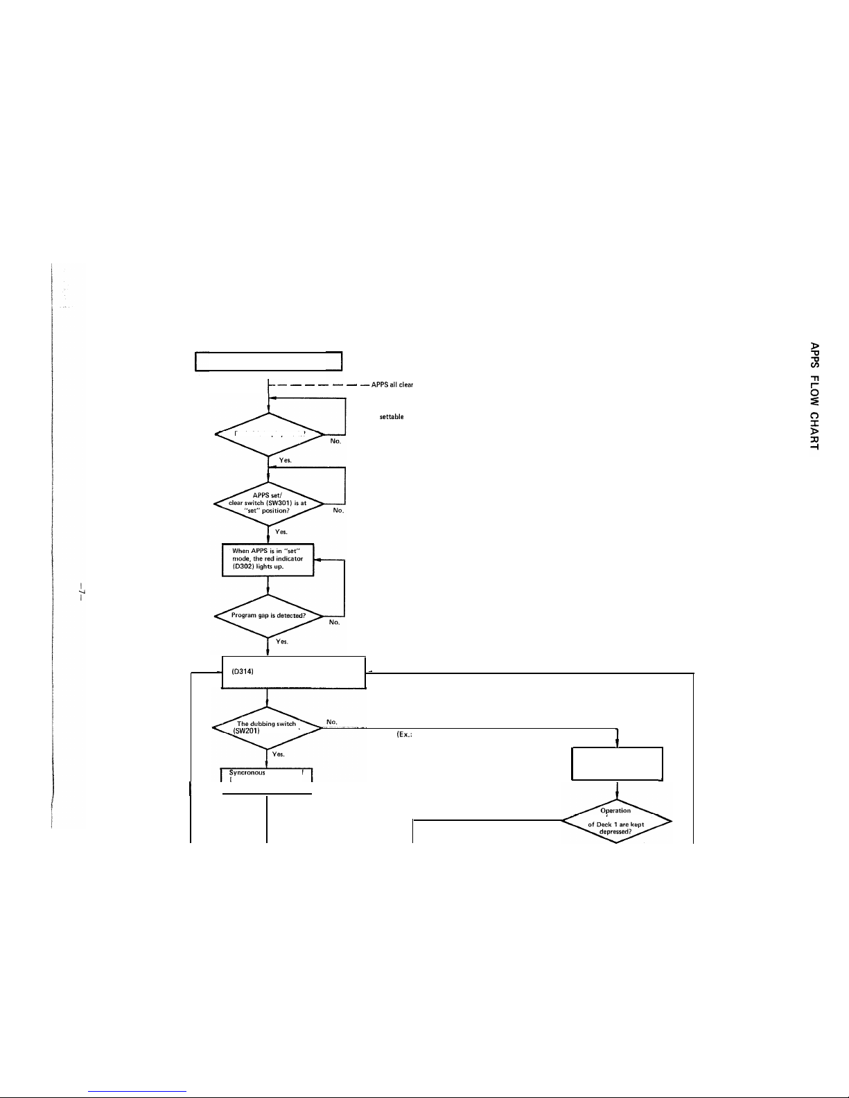
APPS Flow Chart
I
APPS not settable
Deck 1 is in play mode?
The motor stops and the yellow indicator
lights up. The red indicator is still
lit at the time.
is turned on?
of
Deck 1 and Deck 2 is
With Deck 2 in stop or play mode, or
with the dubbing switch turned off)
The motor of Deck 1 gets
in a stop: Deck 2 alone can
be operated.
stopped.
I
No.
buttons (for play mode)
Page 8
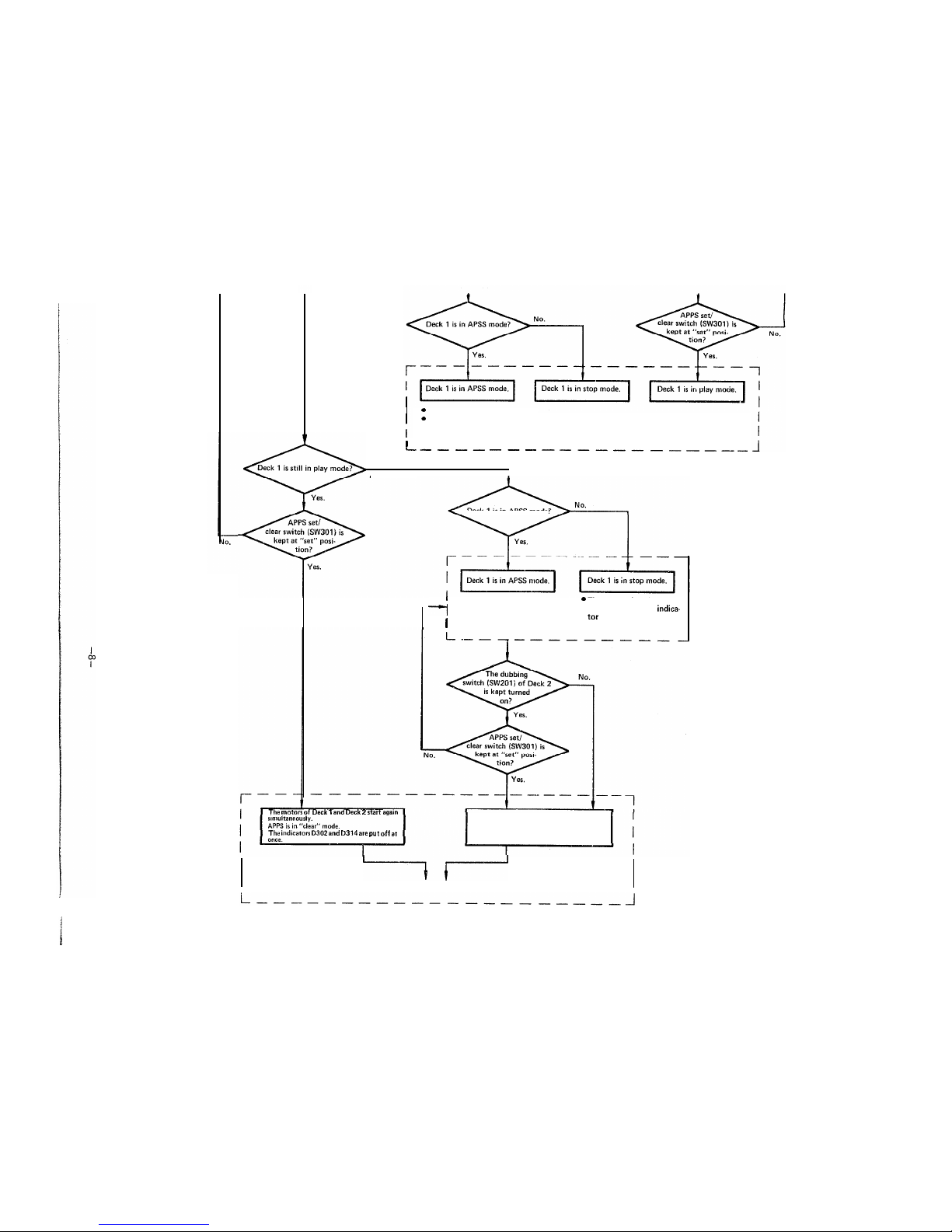
APSS set/clear switch is at “set”
position. (The indicators D302
and D314 are both put off).
Deck 1 is in APSS mode or in stop mode.
No.
I
Deck1is in APSS mode?
l
APPS set/clear switch is at
The motor of Deck 2 is kept
“set” position.
in stop. (The yellow indica-
l
The motor of Deck 1 starts again.
D314 keeps on lighting.)
(The red indicator D302 is put off.)
motors start
The motor of Deck 1 starts again.
D302
D314
put
The yellow indicator D314 is put off.
APPS all clear.
Page 9
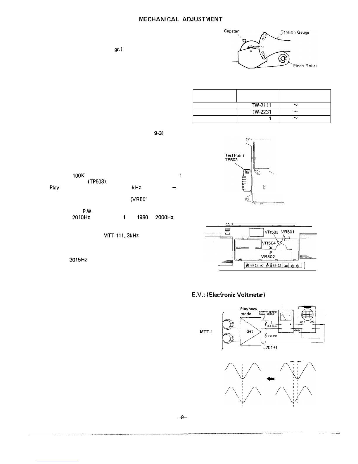
PINCH ROLLER PRESSURE CHECK
1. Place the unit in PLAY mode.
2. Push the pinch roller, at the point shown in Fig. 9-1, by
using a tension gauge (500
so that it will come off the
capstan. Then, release the tension slowly until the pinch
roller hits the capstan again (i.e., the pinch roller is about to
rotate again). Then check the tension gauge is reading
350 gr. to 420 gr.
3. If the reading is outside the range of 350 gr. to 420 gr.
replace the pressure spring of the pinch roller.
TORQUE CHECK AT PLAY, FAST FORWARD AND
REWIND MODES
Put a torque meter cassette in the cassette compartment of the
set, and see that the measured torque in each mode is normal
as follows:
TAPE SPEED ADJUSTMENT (See Figs. 9-2 and
Note:
The high speed operation has priority over the normal speed
operation, and so try to do the adjustment for the former first
and then for the latter.
For High Speed Operation
1. Connect a wow/flutter meter to the Line Output socket
across a
ohm resistor, and shortcircuit the deck
control terminal
2.
a test tape (TEAC, MTT-118, 1
prerecorded)
at
its middle part but not at its start or end point.
3. Adjust the semi-variable resistors
for the deck 1
and VR502 for the deak 2) located on the deck 1 and deck
2 mechanism
Boards, so that the output frequency is
1990 to
for the deck
and
to
for
the deck 2.
For Normal Speed Operation:
1. Play a test tape (TEAC,
prerecorded).
2. Adjust the semi-variable resistors (VR503 for the deck 1
and VR504 for the deck 2) located on the deck 1 and deck
2 mechanism P.W. Boards, so that the output frequency is
2985 to
on the wow/flutter meter for both decks 1
and 2.
RECORD/PLAYBACK HEAD AZIMUTH ADJUSTMENT
1. Make Connection of instruments as shown in Fig. 9-4.
2. Set the Dubbing switch SW201 to the off position and Tape
Selector switch SW105 to Normal position.
3. Adjust the head azimuth adjusting screw so that sine
waveform attains the maximum and the same phase in right
and left.
4. Even without using the oscilloscope, also adjust the head
azimuth adjusting screw so that outputs of both the right
and left channels attain the maximum and the same phase
in right and left.
Note:
For some heads, there may be a phase difference between
right and left channels when the output is made maximum.
In this case, adjust the head azimuth so that such phase
difference will be as small as possible while keeping the
output still maximum.
Pinch Roller
Pressure Spring
Figure 9-l
Mode
Torque meter
cassette
Measured torque
Playback TW-2111
Fast-forward TW-2231
Rewind TW-223
35
60 gram-cm
90
135 gram-cm
90
135 gram-cm
Figure 9-2
Figure 9-3
(Elecfronic Voltmeter)
Test Tape
14
Oscilloscope
E.V.
as small as possible
Figure 9-4
Page 10

OF
BIAS OSCILLATOR FREQUENCY CHECK
1. Make connection of instruments as shown in Fig.
2. Set the function selector switch to “tape” and the beat
cancel switch to “A”.
Record Mode
Oscilloscope
3. Place the unit in record mode, and check that the
frequency counter reads 90
Changing the beat cancel switch from “A” to
position,
see that the frequency counter reading changes by
from the previous value 90
and with the beat
cancel switch set at “C” position, see that it changes by -3
5kHz from previous value 90
Figure
PLAYBACK AMPLIFIER SENSITIVITY CHECK
1. Make connection of instruments as shown in Fig. 10-2.
2. Set the function
switch to “tape”, the volume
control knob to
and the treble/bass tone control
knob to “center” position.
Test Tape
MTT-118
3. Play a test tape
MTT-118,
prerecorded).
Head
4. See that the electronic voltmeter reads about
Figure
RECORD
SENSITIVITY CHECK
Phono input
1.99
Using a CR oscillator, apply a signal of oscillation
(-50
IV)
1
to each input socket of the unit.
Line input
39.8
79mV
2. Check for the input voltage available when the level
(-25
IV)
indicator “OVU” lights up. See Table 10.
External mic input
1.58 m
(-53
Table
For the radio (high frequency) Circuit adjustment, refer to the GF-54542 Service Manual
or GF-5454 Service Manual
Page 11

2SAll43
Record Signal
Microphone Signal
+B Line
APSS Signal Phono Signal
1
2
3
I
4
6
Figure 11
Playback Signal Line in Signal
Page 12

7
8
9
10
11
12
I
L
I I I
Q503,Q504 258562
I
SCHEMATIC
8
9
10
I
11
12
Page 13

I
I
I
1
2
3
4 5
6
A
Figure
WIRING SIDE OF
Page 14

8
I
9
I
10
11
I
12
DE
OF
Page 15

2
I
3
4
6
TA7313P
I
II II I
I
II I
3
I
I
Figure 15 SCHEMATIC
Page 16

2
3
4
I
5
6
2
4
Figure 1.6
SIDE OF P.W. BOARD
5
6
Page 17

SCHEMATIC DIAGRAM AND WIRING SIDE OF
BOARD AT POWER SUPPLY SECTION
OF GF-500
I
SUPPLY CORD
A
2
3
4
5
6
I
Page 18

Ref. No.
SW1 (A
F)
SW101 (A
J)
(A
D)
D)
- 04
05
Names of Switch
Band Selector Switch
Record/Playback Switch
Power Switch
Function Selector Switch
FM Mode Selector Switch
Tape Selector Switch
Switch Position
FM -SW1 -SW2 -AM
Playback
Record
Off
Tape/Line in
Mono
Stereo
SW201 (A
D) Dubbing Switch
SW202 (A
D)
Input Selector Switch
SW203
Beat Cancel Switch
On-Off
Phono
A-B-C
SW204
I
Record Muting Switch
I On
Off
SW205
Deck 1 Main Switch
Deck 2 Main Switch
Deck 1 Plav Switch
Deck 2
Switch
On
Off
SW502 I On
Off
I
SW503
I
On
Off
I
On
Off
Metal
Metal
SW508
Deck 2 Cue/Review Switch
On
Off
Deck 2 Pause Switch
On
Off
SW601
AC/DC Selector Switch
I AC-
DC
I
l
The voltage in each part is measured with
no signal given.
l
As for the radio circuit, the voltage indication without parentheses is in FM stereo
mode,
and that with parentheses is in
mode.
.
for the audio circuit, the voltage indica-
tion is in play mode at normal speed. The
voltage indication with parentheses, for
is in play mode at high
speed.
Parts marked with
important
for maintaining the safety of the set.
sure
to replace these parts with specified ones for
maintaining the safety and performance of
the set.
l
Specifications or wiring diagrams of this
model are subject to change for improvement without prior notice.
Block Diagram of APSS Integrated Circuit
Amplifier
Constant
voltage
Detection Rectifier
Comparisor
Schmidt
circuit
circuit
circuit
FRONT VIEW
Figure 18 BLOCK DIAGRAM OF INTEGRATED CIRCUIT
Page 19

2
3
4
I
I
6
BOTTOM VIEW
TOP VIEW
2
3
4
5
I
6
Figure 19 DECK1MECHANISM
EXPLODED VIEW
Page 20

1
2
3 4
I
I
6
1
BOTTOM VIEW
TOP VIEW
A
1
I
2
3
I
4
I
5
I
6
I
Figure20 DECK 2 MECHANISM EXPLODED VIEW
Page 21

7
I
2
3 4
5
I
6
1
2
3
I
5
I
6
Figure 21 CABINET EXPLODED VIEW
Page 22

2
3 4
5
I
6
A
8
1
2
3
4
5 6
Figure 22 CABINET EXPLODED VIEW
Page 23

PART NO.
DESCRIPTION
CODE
CW106M 1 OMFD, 16V
16V
AB
C316
HW105M
MFD, 50V
AA
RC-EZAI
A
1 OOMFD, 1 OV
AB
21 OAFZZ
1 OOMFD, 16V
AB
A
1 OOMFD, 1 OV
AB
1
16V
AD
3300MFD. 25V
AH
C418
1 OOMFD, 16V
C422
AB
CAPACITORS
Tubular type
capacitor is identified by the symbol MF of
the part No.
this MF does not mean the lead
Unless otherwise specified lead wired capacitors are semiconductor
The terms [CM], [SC], [ML],
and [PP] used here indicate the
types of Capacitor: Ceramic type, Semiconductor type, Mylar type,
Polyethylene Film type and Polypropylene type.
Cl
HLlBOJ
[CM]
AA
AA
-e5%,
AA
AA
AA
AA
AA
AA
AA
Cl6
AA
+.0.25PF, AA
CY223N 0.022MFD.
AA
C28
c43
[CM] AA
AB
AA
C61
AA
C62
C63
[CM] AA
fO.SPF, AA
C64
AA
C67
C69
[CM] AA
[CM] AA
HH150J 1
AA
C72
VCKYMFl HB271J
[CM] AA
HH181J
AA
c73
AA
CY223N
AA
C84
[CM] AA
PART NO. DESCRIP
TIO
N
CODE
C85.87.88 VCTYMFlCY223N
-c30%, AA
Cl
[CM] AA
+-IO%, [CM] AA
0.022MFD.
AA
Cl
14
AA
Cl
16
AA
[CM] AA
Cl 25.126 VCKYMFl HB221
[CM] AA
-c20%, AA
Cl 33,134
EX223K
25V.
AA
MFD,
AA
EX562K 0.0056MFD.
AA
AA
VCKYMFl HBlOPK
MFD,
AA
Cl 73,174
EX273K
25V.
AA
Cl 75,176 VCTYMFl HV392K
AA
Cl 77,178
AB
[CM] AA
AA
25V,
AA
AA
AA
HB181
[CM] AA
C223
AA
C225
AB
C226
AC
C227
AB
C228
[CM] AA
+lO%,
AA
25V,
AA
25V. *IO%,
AA
C272
AA
AA
[CM] AA
AA
c311
0.022MFD.
+-30%, AA
c315
AA
VCTYMFI HV222K
AA
EX104K 0.1 MFD, 25V.
AA
c414 VCTYMFlHV222K
AA
EXlO3K 0.01 MFD, 25V, k-10%,
AA
Page 24

PART NO.
DESCRIPTION
CODE
D319
D401
D403
D404
D405
0508,509,
D512
D513
6,520,
D521
D601,602,
CF3
Tl
TC3
TC5
TC8
vc1.2.
Reverse Current
Prevention
S2076)
Reverse Current
Prevention
S2473)
FM Stereo Indicator
Indicator
Zener.
Zener,
Switching, Built-in
Microphone/Power Amp
Muting (1 S2076)
Reverse Current
Prevention
S2076)
Suge Current Absorber
(1 OE-4)
Reverse Current
Prevention
S2076)
Power
OE-4FD)
FILTER
FM IF 10.7MHz
AM IF 455KHz
TRANSFORMERS
57AFZZ
FM IF
2AFZZ
FM Detector
OAFZZ
AM IF
Power Transformer
Power Transformer
(GF-500)
COILS
FM RF
Antenna
Bar Antenna
SW2 Oscillator
Oscillator
04AFZZ 6.8mH
Bias Oscillator
4AGZZ 47pH
Choke,
Deck
Choke,
Deck 2
CONTROLS
Antenna
Oscillator
072AFZZ Trimmer, AM Oscillator
AA
AC
AC
AC
AB
AB
AB
AB
AB
AD
AE
AC
AC
AC
AV
AC
AA
AC
AD
AM
AC
AC
AC
AC
AC
AC
AB
AB
AC
AC
AC
AC
Variable Capacitor, Tuning
with Trimmer
RF
Trimmer
Oscillator
AN
Trimmer
-24
PART NO.
DESCRIPTIO
N
CODE
vc5
VR102
VR502
VR503
VR504
Antenna
Trimmer
Oscillator
Trimmer
Fine Tufiing
AE
ohm(B), V.C.O. Adjust
Tone
Control
50K ohm(73Z). Balance AM
Control
20K ohm(339Z), Volume
High AC
Speed Adjust
ohm(B), Deck2 High AC
Speed Adjust
AC
Normal Speed Adjust
20K ohm(B), Deck2
AC
Normal Speed Adjust
ELECTROLYTIC CAPACITORS
Unless otherwise
electrolytic
are
type.
Cl 65.167,
Cl 68
C42
c44
c47
c77
C78
C81
Cl 19,120
Cl 23,124
Cl 27,128
Cl 31 ,I 32
Cl 35
Cl 36
A
16V
A
16V
1 MFD, 50V
A
1 OV
RC-EZAI
50V
RC-EZAI
RC-EZAI 07AFl A
EC475M 4.7MFD. 25V
RC-EZAI
A
OOMFD,
OV
1 MFD, 50V
1 OOMFD, 16V
HW334M 0.33MFD, 50V
4.7MFD, 25V
A
1 OOMFD, 1 OV
16V
OAFZZ
OOMFD, 16V
1 OMFD.
MFD, 50V
Cl
HW474M 0.47MFD. 50V
RC-EZAI
1 OOMFD, 16V
Cl 72
RC-EZAI
OMFD,
C224
C273
C274
21 OAFZZ
OOMFD, 16V
1 OOMFD. 1 OV
07AFl
1 OOMFD, 16V
47MFD,
IOMFD,
RC-EZYI
IOMFD, 16V
IOMFD,
RC-EZYI
50V
A8
A8
A8
AB
A8
A8
A8
AB
AB
AB
A8
AB
AB
AB
AB
A8
A8
AB
AB
AB
AB
AB
A8
AB
A8
A8
A8
AB
A8
AB
AR
AB
A8
AB
AB
AB
AB
Page 25

PART NO.
INTEGRATED
01
ITD62504/- 1
0103,104
a304
Q306
-L/-A
Q501
Q503
Q504
a505
PARTS
TO ORDER REPLACEMENT PARTS”
To have your order filled promptly and correctly, please furnish the following information.
1. MODEL NUMBER
2. REF. NO.
3. PART NO.
4. DESCRIPTION
____
NOTES:
Parts marked with
are important for malntalning the safety of the set. Be sure to replace these parts
specified ones for malntainlng the safety and performance of the set.
CODE
FM Front End (TA7335P)
FM IF/AM Mixer,
Oscillator, IF(AN7223)
FM Multiplex (TA7343P)
Deck1 , Pre-amp.
Pre-amp.
L)
Switching, APSS Muting/
Muting/Equalizer Selector
Line Amp. (M51544L)
Record Amp.
Switching, High Speed/
Metal Equalizer
Phono Amp. (M51521
Level Meter Amp.
APSS Circuit (IR3108A)
Nor Circuit (4001 BP)
Switching, Voltage
Control (TD62504)
Power Amp.
APPS Circuit
APPS Circuit
Constant Voltage
Regulated
Deck
Motor Drive
Deck 2, Motor Drive
(288739 C)
Deck 1, Motor Stop
Deck 2, Motor Stop
Solenoid Drive
AG
AK
AG
AG
AG
AG
AG
AF
AG
AH
AG
AE
AG
AR
Switching, Built-in
Microphone Power
Supply (2SAl 143)
Switching, Equalizer
AB
Muting (2SC2603 F) A8
Bias Oscillator
AD
K)
ALC Improvement of
AB
Metal Mode
APPS Circuit
A0
F)
Switching, APPS Indicator AB
AB
AB
AD
D306
AD
AD
0307,308,
D312.313 VHDI
AD
AD
D315
AC
AD
PART NO.
DESCRIPTION
CODE
Q508
Deck 1,
Speed A6
Motor Control
Deck 2, Normal Speed A8
Motor Control
Switching, High Speed A8
Control (2SC2603 F)
DIODES
Static Protector
FM Overload (152076) A8
Reverse Current
A0
Prevention (1 S2076)
Forward Direction Voltage AB
Absorber (1 S2076)
Reverse Current
Prevention (1 S2473)
AB
D201
D203
D204
AB
AA
AB
AB
AB
D206 VHDI
0207,208,
D212
Absorber (152473)
Reverse Current
Prevention (1 S2473)
ALC (152076)
Reverse Current
Prevention (152473)
ALC (152473)
Reverse Current
Prevention (152473)
Reverse Current
Prevention (152473)
ALC (1 S2076)
D302
Level Meter
05R54)
Reverse Current
Prevention (1 S247)
Reverse Current
Prevention
S2473)
Dubbing Indicator
APPS Indicator
Reverse Current
Prevention (152473)
Reverse Current
Prevention (1
Reverse Current
Prevention (1
Reverse Current
Prevention (152076)
End Stop Indicator
Reverse Current
Prevention (1 S2473)
Reverse Current
Prevention (1 S2473)
Reverse Current
Prevention (152473)
AH
A0
AD
AC
AB
AA
AB
AD
AB
AA
Page 26

PART NO.
DESCRIPTION CODE
C423
AA
HF1032 0.01
RESISTORS
Tubular type carbon film resistor
is
by the
symbol
of the part No. VRD-MFOOOOOOO: this MF does not
mean lead
Unless
lead wired
are
Carbon type.
820K ohm
680 ohm
220 ohm
270 ohm
470 ohm
ohm
ohm
470 ohm
33 ohm
R64.65
47 ohm
330 ohm
RI 01
82 ohm
R103.104
150K ohm
09,110
ohm
RI 17,118
ohm
R121.122
220 ohm
560 ohm
330K ohm
02J
ohm
12K ohm
RI 33,134
RI 37,138
39K ohm
RI 63,164
220 ohm
15K ohm
820 ohm
220 ohm
680K ohm
33K ohm
820 ohm
AA
AA
AA
AA
AA
AA
AA
AA
AA
AA
AA
AA
AA
AA
AA
AA
AA
AA
AA
AA
AA
AA
AA
AA
AA
AA
AA
AA
AA
AA
AA
AA
AA
AA
AA
AA
AA
AA
AA
AA
AA
AA
AA
AA
AA
AA
AA
AA
AA
AA
AA
AA
AA
AA
AA
AA
AA
AA
R316.317
0
R241.242
R255.256
PART NO. DESCRIPTION
CODE
ohm
100 ohm
ohm
220 ohm
120K ohm
220 ohm
680K ohm
220K ohm
ohm
22K ohm
180 ohm
12 ohm
ohm
15K ohm
15 ohm
220 ohm
220K ohm
ohm
33K ohm
56K ohm
ohm
ohm
82K ohm
560 ohm
ohm
220K ohm
680 ohm
330 ohm
33K ohm
560K ohm
330 ohm
22K ohm
560 ohm
56K ohm
AA
AA
AA
AA
AA
AA
AA
AA
AA
AA
AA
AA
AA
AA
AA
AA
AA
AA
AA
AA
AA
AA
AA
AA
AA
AA
AA
AA
AA
AA
AA
AA
AA
AA
AA
AA
AA
AA
AA
AA
AA
AA
AA
AA
AA
AA
AA
AA
AA
AA
AA
AA
AA
AA
AA
AA
AA
AA
AA
AA
AA
AA
AA
ohm
AA
220K ohm
ohm
220K ohm
ohm
39K ohm
AA
AA
AA
AA
AA
AA
AA
Page 27

PART NO.
DESCRIPTIO
N
CODE
PART NO.
DESCRIPTION
CODE
Spring, Head Base Return AA
Spring, Eject Lever
AA
Return
Spring, P.A.D. Cam
AA
Interlocking Arm
Spring, Earth
AA
Spring, Deck 2 Record AA
Conversion
AA
Belt, Flywheel Drive
AC
Belt, Playback
AB
Belt, Fast Forward/Rewind AC
228 JKNBK0270AFSA
229
JKNBR0201 AFSB
230
231 JKNBK0271 AFSA
235
236
237
LANG00861 AFFW
238
239
242
243
244
245
246
249
249
250
251
252
253
254
255
257
258
259
260
261
262
AFZZ
263
264
267
268
269 MSPRT0796AFFJ
270
272
273
274
275
276
278
279
279
280
281
AFZZ
Felt, Battery Compartment
AA
Knob, Tuning
Knob, APPS Set/Clear
Switch
Button, Dubbing Start
Knob, Fine Tuning
Digital Tape Counter
Bracket, External Speaker
Sockets
Terminal, Junction
Bracket,
Retaining
Bracket, Dial Pullety
Retaining
Frame
Holder, L.E.D.
Holder, Handle
Tuning Knob
Nylon Band, 60mm
Cover, Battery
Compartment (GF-500Z)
Cover, Cassette
Compartment (GF-500)
Screw, Cabinet
Screw, AC Socket
Retaining
Screw, AC Power Supply
Socket Cover Retaining
Lever, Dubbing Start
Lever, Record/Playback
Selector
Lock Lever, Cassette
Compartment
Damper, Cassette
Compartment
Rod, Record/Playback
Selector Lever
Spring, Battery Terminal
Spring, Batten/ Terminal
Spring, Cassette
Compartment Lock Lever
Spring, Cassette
Compartment Guide
(Right)
Spring, Cassette
Compartment Guide
Spring, Dubbing Start
Lever
Spring, Cassette
Compartment (Left)
Spring, Cassette
Compartment (Right)
Spring, Dial Stringing
Spring, Record/Playback
AG
AE
175
176
177
AC
AG
AK
AC
178
AFFJ
179
180 NBALS0006AGFJ
181
182 NBLTK0208AFZZ
183
184
185
186
187
188
189
01 AFOO
190
191 QLUGPOl
11 CEFW
192 RHEDZ0055AFZZ
193
OOAFZZ
194
195
14AFZZ
AA
A0
Bearing, Capstan
Bearing, Flywheel Thrust
Flywheel
Gear, P.A.D. Cam Drive
Pinch Roller
Guide, Cassette
Spacer, Motor
Lug Terminal
Sitter Head
Head, Erase
Head, Deck 1 Playback
Head, Deck 2 Record/
Playback
Plate, Deck 2 Lock
Pin, Pause Cam Lock
AE
AA
AK
AD
AE
AC
AA
AD
AH
AN
AN
AN
AC
AC
AB
AA
AC
AA
AA
196
197
AC
AD
AA
Lever
Lug Terminal
Screw, Deck2 Pause
Switch Retaining
AA
AA
AD
AC
199
AC
AF
MISCELLANEOUS
201
AC
Front Cabinet Assembly
Front Cabinet
AB
AC
AA
202
202
203
204
AH
Window, Dial
AG
Battery Compartment
AG
244AFSA Cassette Compartment AL
Assembly
GFTAC121
Cassette Compartment
AH
Decoration Plate, Cassette AD
Compartment
Transparent Plate, Deck 1 AH
Cassette Compartment
Transparent Plate, Deck 2 AH
Cassette Compartment
Punching Metal, Woofer
(GF-500)
HPNC-0161 AFSA Punching Metal, Tweeter AE
179AFSD Cover, AC Power Supply AC
Socket
Dial Pointer
AC
AC
Tone Control
/Deck 2 Tape Selector/
Deck 2 Record Muting
Speed Selector
AE
AA
AA
AA
A0
A0
AB
AA
AB
AC
AB
AB
AA
AB
AA
206
207
8208
209
209
210
220
221
222
223
224
225
226
227
Selector Lever
Belt, Tape Counter
Drum
Pulley, Dial Stringing
Pulley, Dial Stringing
Cover, Power Supply
(GF-500)
Cover, Power Supply
(GF-500)
Cushion, Coil (Tuner
Cushion, Battery
Compartment (GF-5002)
Cushion, Battery
Compartment
Cushion, Built-in
Microphone
Page 28

PART NO. DESCRIPTION
CODE
104
Take-up/Supply Turntable AU
Block. Assembly
Chassis, Take-up/Supolv AG
5
105
106
107
108
109
110
112
113
114
116
i17
118
119
120
121
122
123
124
12.5
126
27
128
129
130
131
132
133
1
2
3
4
Turntable
LRTNP0051 AFZZ
Retaining Ring, Sensor
Lever
Washer, 2.1 mm Dia.
Washer, 1.2mm Dia.
Washer, Back Tension
Lever, Fast Forward
Interlocking
interlocking
Spring,
Tension
Pressure
Reture
Turntable, Take-up
AFZZ
Turntable, Supply
Idler, Playback
1 AFFJ Spring, Auto Stop Sensor
Lever
Head
Sub-chassis, Head
Pin, Pause Lever
1
Plate, Operation Lever
Retaining
Bracket, Deck 1 Motor
Retaining
Retaining
Retaining Ring
4mm Dia.
Cushion, Motor
Xtl Omm
Nut, Capstan Bearing
Retaining
Wire Holder
Arm, Deck 2 Record
Operation Sensor
Cam Gear,
Cam Gear, Pause
Lever, Deck 1 Lock
Release
Lever, Deck 2 Lock
Release
Lever, Fast Forward
Lever, Rewind
Lever, P.A.D. Cam Gear
Lever, Pause Cam Gear
Lock
Lever, Pause
Lever, Deck 2 Erase
Prevention
AA
AA
AA
AA
AA
142
AC
MLEVP0361 AFOO
AB
AF
AA
AA
AA
AA
AF
AD
AC
AD
AA
AB
AD
AA
AC
AH
AA
159
AA
AC
AA
AC
AA
AA
AC
AB
AB
AC
AC
AR
-28-
134
135
PART NO.
136
137
LEVP03
138
139
140
141
144
145
146
148
149
150
151
152
153
154
155
156
157
MSPRC0271 AFFJ
158
160
161
162
163
164
AFFJ
165
166
167
168
169
170
171
172
173
174
MSPRD042CAFF.J
CODE
Lever, Operation
AA
Plate. Deck 1 Operation A8
Lever Blocking
Plate, Deck 2 Operation
Lever Blocking
Lever, One-touch
AA
Interlocking
Lever, Main Switch
AA
Interlocking
Lever, Main Switch
AB
Retaining
Lever, Playback
AB
Lever, Deck 2 Record
AC
Interlocking
Lever, Brake
A8
Lever, APSS Switch
AA
Interlocking
Lever, Fast Forward/
AA
Rewind Interlocking
Lever, Eject
AB
Lever, Deck 2 Record
AB
Lever, Deck
Solenoid AB
Interlocking
Lever, Deck 2 Solenoid AB
Interlocking
Plate, Deck 1 Lock
AC
Plate, Deck 1 Lock
AC
Lever, Deck 2 Record
AC
Conversion
Spring, Fast Forward/
AA
Rewind Interlocking
Lever
Spring, Head Azimuth AB
Spring, Operation Lever AA
Spring, Operation Lever AA
Blocking Plate
Spring, Pause Lock Pin AA
Retaining
Spring, Brake Lever
AA
Pressure
Spring, Deck 1 Solenoid AA
Return
Spring, Pause Operation AA
Lever
Spring, Pinch Railer
AA
Pressure
Spring, Pause Cam Lock AA
Lever
Spring, Pause Cam Gear AA
Spring, Pause Lever
AA
Return
Spring, Rewind Lever
AC
Spring, Auto Stop Sensor AA
Control
Spring, Deck 2 Record AA
Sensor Arm
Spring, Playback Lever AA
Return
Spring, Pinch Roller
AA
Return
Spring, Head
AA
Pressure
Spring, Deck 1 Operation AA
Lever Lock Plate
Spring, Cassette Retaining AA
Plate
Head
AA
Retaining
Spring, Lock Release
AA
Lever
Spring, Fast Forward/
AA
Record Button Lever
Return
Page 29

PART NO.
DESCRIPTION
CODE
03J
ohm
R403.404.
820 ohm
AA
AA
AA
270 ohm
AA
33K ohm
AA
150 ohm
AA
AA
AA
AA
AA
AA
AA
R505.506 VRD-ST2CDlOl
AA
AA
AA
AA
AA
AA
AA
R523.524
A5
RR-XZI 022AFZZ
ohm
10 ohm,
Fusible
470 ohm
ohm
150 ohm
ohm
Carbon
100 ohm, 1/6W,
Carbon
ohm,
&5%,
Carbon
ohm
Carbon
220 ohm
1 OOK ohm, 1/6W.
Carbon
Carbon
2.2 ohm, 1/4W,
2.7 ohm,
Fusible
0 ohm (Jumper)
AE
AA
OTHER CIRCUITRY PARTS
SW506
QSW-FOI 77AFZZ
8107
CNP2
01
Plug
with ‘Wire Leads
AB
x2 with Wire Leads
Plug 2 with Wire Leads
AA
QCNCMI 33GAFZZ Plug,
(Tuner)
AD
CNPI 02,103 QCNCM095BAFZZ Plug,
(Speaker)
AB
04
Plug,
05
84EAFZZ Plug,
AC
CNP501
Plug,
AC
CNP502 OCNCM592LAFZZ
Plug,
Pin
AC
CNP503
(Test Point)
AA
QCNCM431
Plug,
AA
CNS2
with Wire AC
Leads
CNSI 01
QCNW-1 592AFZZ Socket,
with Wire
AG
Leads
02,103 QCNW-1609AFZZ Socket, 2Pin with Wire
Leads
04
Socket,
with Wire Leads
Socket,
with Wire Leads AG
QCNW-1593AFZZ Socket,
with Wire AL
Leads (GF-500Z)
Socket,
with Wire
Leads
with Wire
AH
Leads
Socket,
with Wire
A8
Leads (GF-500Z)
QCNW-1741 AFZZ
Socket,
with Wire
Leads
F-500)
AA
SO601,602
PART NO.
QJAKJOI
SOL501
2PB58SA
-A-F
52AFZZ
01 -A-J QSW-S0373AFZZ
03-A-D
04
05
SW201 -A-D
SW204
SW205
SW203
SW501
SW502
QSW-FOI 48AFZZ
SW503
QSW-FOI 37AFZZ
SW505
SW507
SW508
QSW-FOI 71 AFZZ
QSW-FOI 71 AFZZ
Assembly
OAFZZ
DESCRIPTION
CODE
Fuse, T1.25A (GF-500Z)
AD
Fuse, 1.5A (GF-500)
Socket, Line/Phone Input
Earth Terminal
Sockets, Line Output
AL
Sockets, External Microphone
Sockets, External Speaker AE
Sockets, Headphones
AF
Motor with Motor Pulley AW
AC Input/DC 12V Input
AH
AC Input/DC 12V Input
AH
Solenoid
AH
Speaker, Woofer
Speaker, Woofer
Speaker, Tweeter
AC
Switch, Band Selector AM
Switch, Record/Playback AF
Switch, Power
Switch, Function Selector
Switch, FM Mode
Selector
Switch, Deck2 Tape
AS
Selector
Switch, Dubbing
Switch, Deck2 Record
Muting
Switch, Dubbing Speed
Selector
Switch, Input Selector AF
Switch, Beat Cancell
AD
Switch, APPS Set/Clear AC
Switch,
Main
AE
Switch, Deck2 Main
AE
Switch, DeckI Playback AE
Switch, Deck2 Playback AE
Switch, Deck1 Normal/ AE
Cr02 Selector
Switch, Deck2 Normal! AE
Selector
Switch.
APSS
AC
Switch, Deck2 Cue/
AC
Review
Switch, Deck2 Pause
AC
Switch, AC/DC Selector
Wiring Lead, Telescopic
Rod/Antenna
Wire Leads
AC
Wire Leads
MECHANICAL PARTS
100
JBOTNOI
Deck I Button Block
AN
I
Assembly
AE
AE
APSS
APSS
AE
14AFZZ Deck
Button Block
AN
Assembly
103
AE
AE
LCHSM041
Main Chassis
71 AFFW Plate, Head Base
Page 30

PART NO.
282
283
284
285
287
24AFZZ
QFSHD2051 AFZZ
289
290
291
292
293
294
PFLT-0507AFO0
294
295
296
91 AFOO
297
QACCD0051 AFOO
QACCZO051 AFOO
QPLGA0251 AFZZ
01 AFZZ
SPAKP0301 AFZZ
DESCRIPTION CODE
Guide, Cassette
AC
Compartment (Left)
Guide, Cassette
AC
Compartment (Right)
Heat Sink
AC
Shild Plate, Rear Cabinet AD
FM/SW Telescopic AM
Antenna
Fuse Holder
AA
AA
Terminal, Battery
AB
Built-in Microphone
AF
Shild Plate, Rear Cabinet AA
Cushion, Prevention of
Vibration
Felt, Rear Cabinet
AA
Felt, Rear Cabinet
Cushion, Bar Antenna
Cushion, Tuner Frame
AB
Tuning knob AA
AC Power Supply Cord
AH
AC Power Supply Cord AL
AC Power Supply Cord
AM
(GF-500Z)
AC Power Supply Cord
AH
(GF-5002)
Adaptor, AC Plug
AE
Cassette Tape
AK
Packing Add, Left Side
AE
(GF-500Z)
Packing Add, Right Side AE
(GF-SOOZ)
Packing Case (GF-SOOZ) AM
Bag, Unit (GF-500Z)
Bag, Operation Manual AA
(GF-SOOZ)
PART NO.
DESCRIPTION
COD
Caution Label, Arabic, AC AA
Caution Label, Power
Supply (GF-500)
AA
Warranty Card, For
AC
(GF-500Z)
in Australia (GF-500Z)
Operation Manual
AK
AA
Label, Free From Taxes AB
(GF-500Z)
Caution Label, (GF-500Z) AA
Label, Characterization
AC
Label, Characterization AC
(GF-500)
Label, Characterization AC
AC
PWB ASSEMBLY (Not Replacement Item)
Tuner Circuit
Amp. Circuit (GF-SOOZ)
(Combined
Assembly)
Amp. Circuit (GF-500)
(Combined
Assembly)
(Combined
Assembly)
SHARP CORPORATION
OSAKA, JAPAN
SHARP ELECTRONICS CORPORATION
Executive Office:
10 Sharp Plaza,
Paramus,
New Jersey
07652
Regional Offices
Distribution Centers:
2 Sharp Plaza,
Paramus,
New Jersey
07652
20600
Alameda St.
Carson,
90810
430 E.
Rd.
Countryside, Illinois
60525
U.S. Subsidiary of Sharp Corporation, Osaka, Japan
Parts Centers:
P.O. Box 664
Paramus,
New Jersey
07652
20394
Long Beach,
90810
637-9488
La Grange,
Illinois
60525
482-9292
Writer and Editor: Engineering Administration of Audio Systems Group, Sharp Corp.
 Loading...