

Page 1
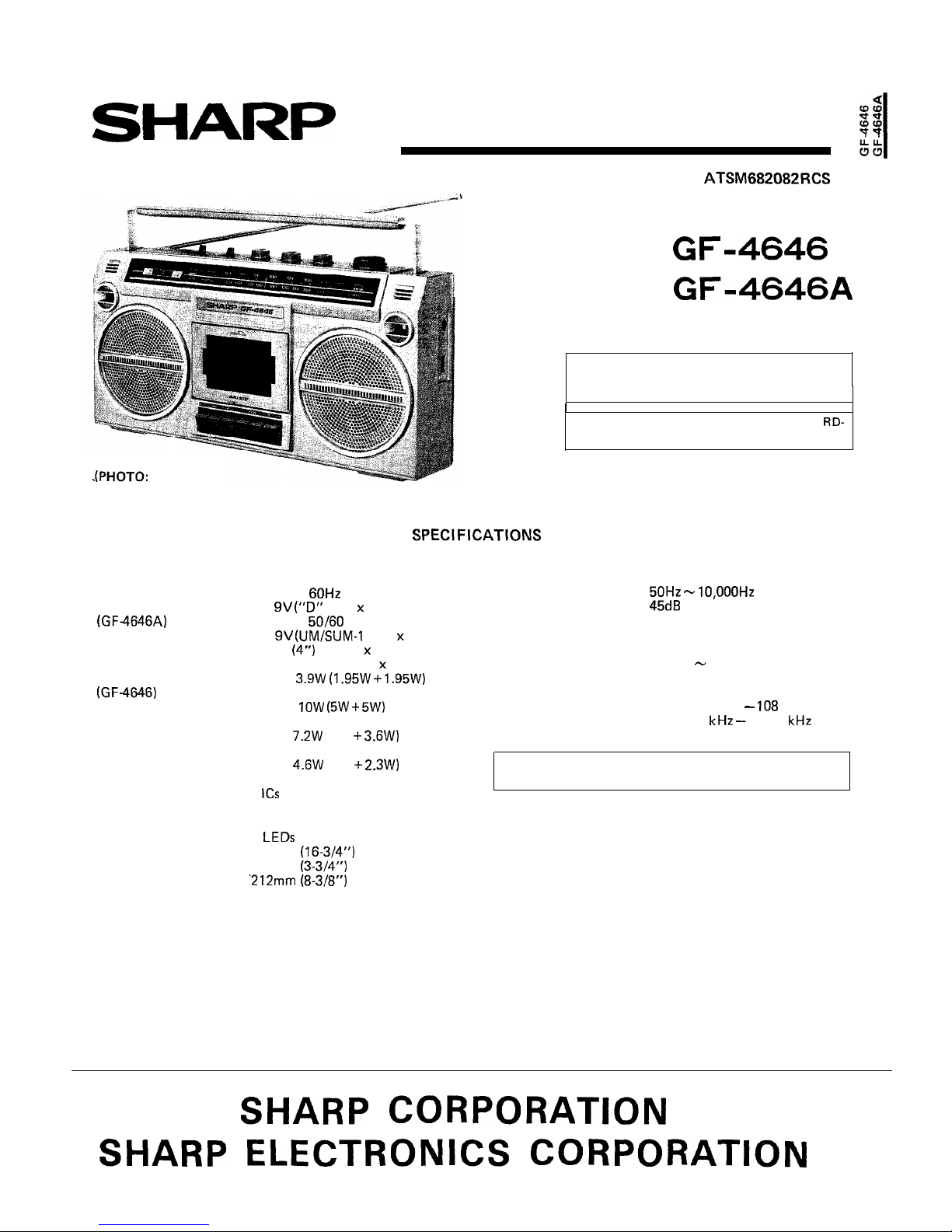
SERVICE MANUAL
OUTSTANDING RECEPTION THE WORLD OVER
GF-4646)
GENERAL
Power source:
(GF-4646)
Speakers:
Output power:
Output power:
(GF-4646A)
Semiconductors:
Dimensions: Width;
Depth;
Height;
Weight:
In the interests of user-safety the set should be
restored to its original condition and only parts
identical to those specified be used.
For the mechanical adjustment, refer to the
620/A Service Manual already issued.
AC 120V
DC
type x 6)
AC 240V
Hz
DC
type x 6)
10 cm
woofer x 2
Ceramic type tweeter x 2
MPO;
+
(AC operation)
PMPO;
(5W +
(AC operation)
MPO;
(3.6 +
(AC
operation)
TAPE RECORDER
Tape:
Compact cassette tape
Frequency response:
Signal/noise ratio:
Input sensitivity and impedance:
External mic.; 600 ohms
Loaded impedance:
Headphones; 8 ohms
25 ohms
RADIO
Frequency range: FM; 87.6 MHz
108 MHz
AM; 525
1,605
RMS;
(2.3 +
(DC
operation, 10% distortion)
5
4 transistors
11 diodes
2 LEDs
426mm
96mm
2.8 kg (6.1 tbs.) without batteries
Specifications for this model are subject to change without
prior notice.
Page 2
FOR A COMPLETE DESCRIPTION OF THE OPERATION OF THIS UNIT,
PLEASE REFER TO THE OPERATION MANUAL.
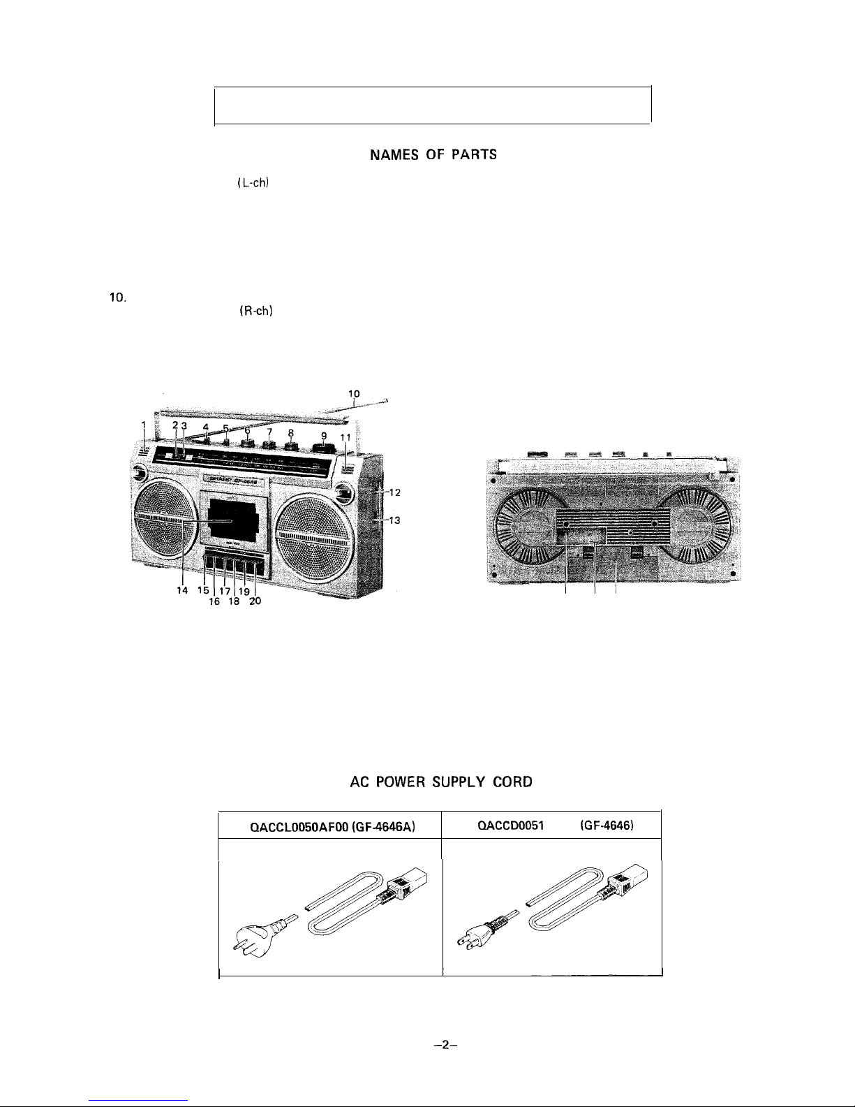
1. Built-in Microphone (L-ch)
2.
Power/Battery indicator
3. FM Stereo Indicator
4. Band Selector
5. Function Selector
6. Volume Control
7. Tone Control
8.
Balance Control
9. Tuning Control
11.
Built-in Microphone (R-ch)
12.
Headphones Jack
13.
14.
15.
16.
17.
18.
19.
20.
21.
22.
23.
Figure 2-l
AC Power Supply Socket
Cassette Holder
Record Button
Rewind Button
Playback Button
Fast-forward Button
Stop Button
Eject Button
Beat Cancel Switch
External Microphone Jacks
Battery Compartment Lid
21
22 23
Figure 2-2
AFOO (GF-4646)
Page 3
Caution:
Prior to the disassembly, be sure to remove the AC power
supply cord, cassette tape and batteries from the unit.
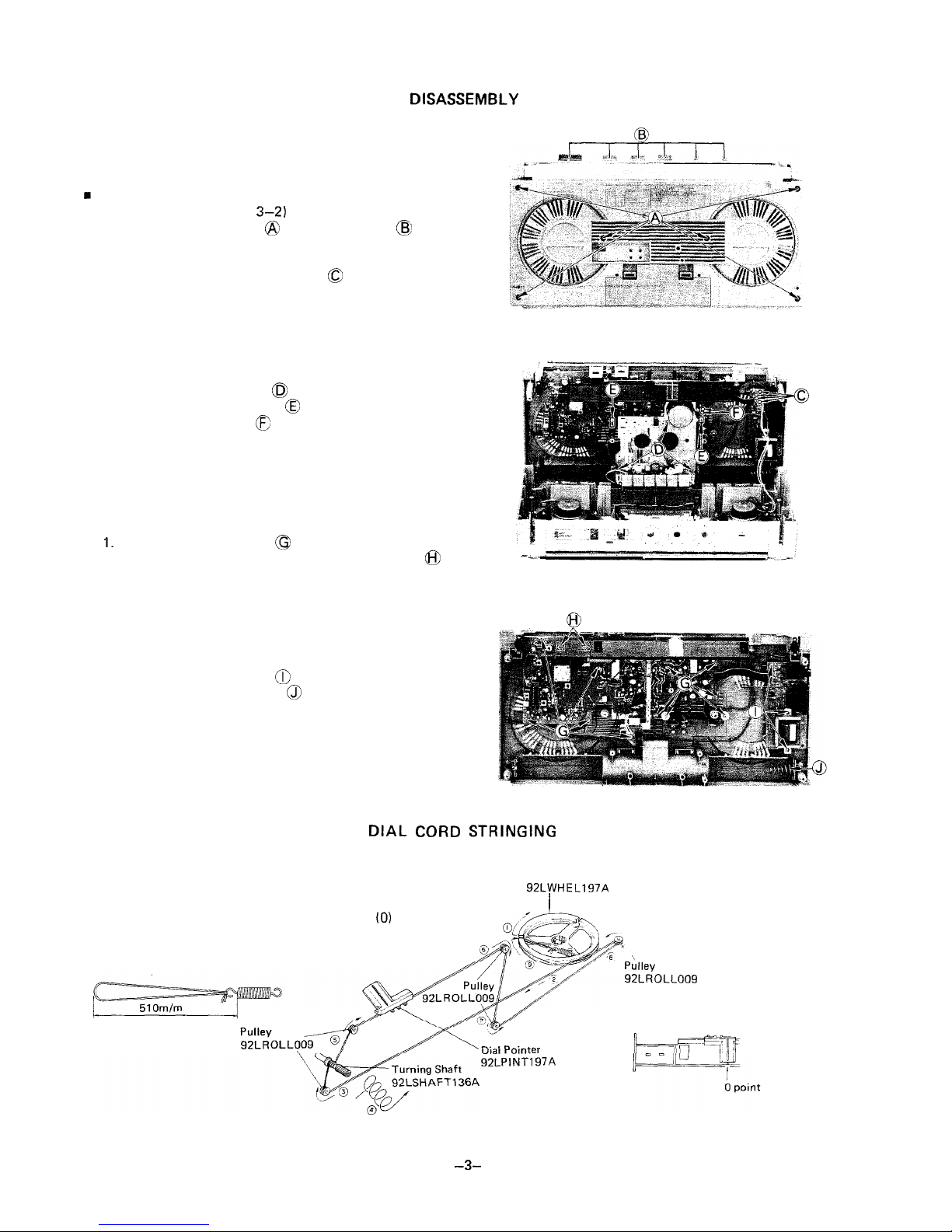
FRONT CABINET REMOVAL
(Refer to Figures 3-l and
1. Remove the six screws
and the six knobs
2. Push the eject button to open the cassette holder.
3. Pull the front cabinet frontward by holding its upper
part and disconnect the three tips
n
MECHANISM BLOCK REMOVAL
(Refer to Figure 3-2)
1. Remove the three screws
.
2. Disconnect the two sockets
.
3. Unsolder the two tips
, then the mechanism block
can be removed.
n
MAIN P.W.B. REMOVAL
(Refer to Figure 3-3)
Remove the eleven screws
.
2. Remove the LED P.W.B. from the two stoppers
,
then the main P.W.B. can be removed from the back
cabinet.
. POWER P.W.B. REMOVAL
(Refer to Figure 3-3)
1. Remove the three screws
2. Remove the battery spring
, then the power P.W.B.
can be removed from the back cabinet.
Figure 3-l
Figure 3-2
Figure 3-3
1) Turn the drum fully clockwise and stretch its cord cover
the parts in the numerical order-as shown in Figure 3-4.
2) Turn the tuning control shaft fully counterclockwise, and
Dial Cord Wheel
fix it with the pointer aligned with the zero (0) point on
the frame. See Figure 3-5.
Figure 3-4
4
turns
Figure 3-5
Page 4
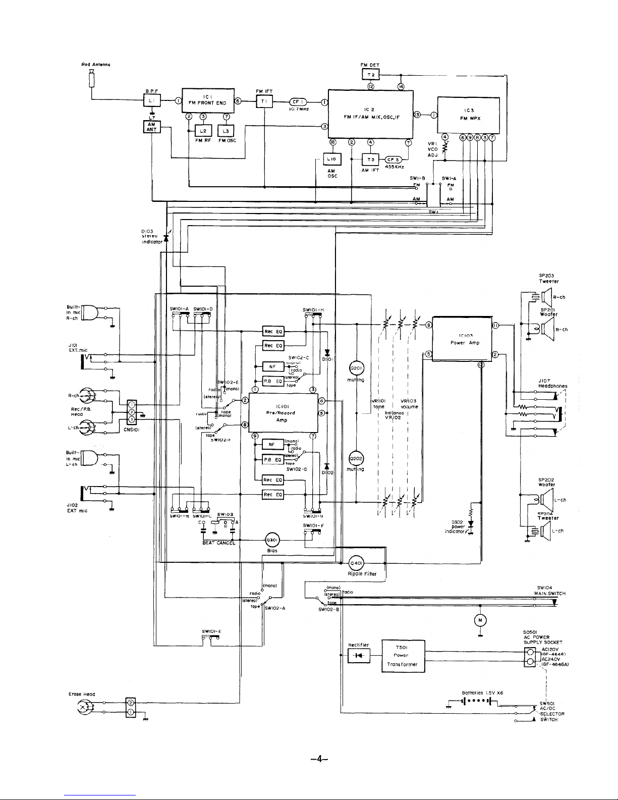
Figure 4 BLOCK DIAGRAM
Page 5
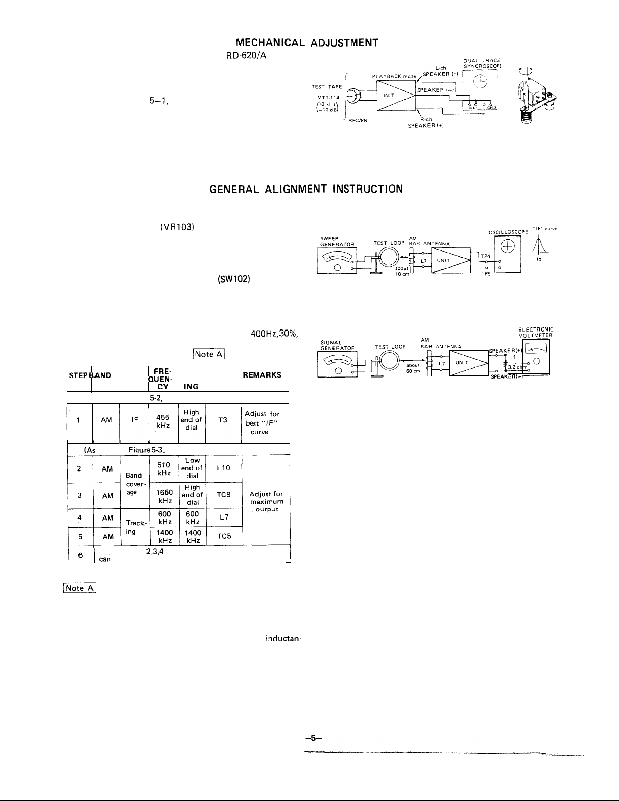
Except for the following item, refer to the
Service
Manual already issued.
n
RECORD/PLAYBACK HEAD AZIMUTH ADJUSTMENT
As shown in Figure
make connection of instrument,
and adjust the head azimuth adjusting screw so that the
output signals from both channels will have maximum
waveform with the same phase in right and left.
HEAD
(+l
Figure 5-l
Should it become necessary at any time to check the align-
ment of this receiver, proceed as follows;
1. Set the volume control
to maximum.
2. Attenuate the signals from the generator enough to swing
the most sensitive range of the output meter.
3. Use a non-metallic alignment tool.
4. Repeat adjustments to insure good results.
5. Set the Function Selector Switch (SW102) to “radio”
position.
AM IF/RF ALIGNMENT
l
Set the signal generator to produce a signal of
AM modulated.
l
For adjustments in steps 4, see
.
STAGE
SETT- MENT
TEST FRE- DIAL ADJUST-
IF (As shown in Figure 5-2, make connection of instruments.)
RF (As shown in Fiqure 5-3, make connection of instruments.)
Repeat steps
and 5 until no further improvement
ALIGNMENT
Figure 5-2
Figure 5-3
Check the alignment of the receiver antenna coil by
bringing a piece of ferrite (such as a coil slug) near the antenna
loop stick, then a piece of brass. If ferrite increases output,
loop requires more inductance. If brass increases output, loop
requires less inductance. Change loop inductance by sliding the
bobbin toward the center of ferrite core to increase inductan-
ce, or away to decrease inductance.
Page 6

FM IF/RF ALIGNEMNT
l
Set the signal generator to produce a signal of
FM modulated.
TEST FRE- DIAL
STEP BAND STA-
SET- JUST-
REMARKS
GE
IF
shown in Figure
make connection of instruments.)
6
Repeat steps
and 5 until no further improvement
can be made.
FM STEREO
l
Set the Band Selector Switch
to “FM” position and
Function Switch
to “stereo” position.
l
As shown in Figures 6-3 and 6-4, make connection of
instrument.
FREQUENCY
DIAL
POINTER
MENT
REMARKS
Adjust for
38
To
Figure 6-4 FM DUMMY
MH*,
Figure 6-l
Figure 6-2
Figure
Figure 6-3
q
Figure 6-5 ALIGNMENT POINTS
DIAGRAM
Resistor:
l
Unless otherwise specified all resistance in ohms,
ohms
2. Capacitor:
* Unless otherwise specified all capacitance in microfarads,
Picofarads
4.
Printed resistor
5. Parts marked with ”
”
are important for main-
taining the safety of the set.
Be sure to replace these parts
with specified ones for maintaining the safety and perform-
l
Temperature compensation
3. Voltage reading are measured with Digital
under
no signal condition in tape position.
AM mode
FM mode
-6-
---.--.
--
Page 7

1
2
3
4
5
6
A
1
2
3
4
6
Figure 7 WIRING
Page 8

7 8
9
10
11
12
6
7
8
9
10
I
12
Page 9

1
2
3
4
5
6
7
FILTER
(Specifications or wiring diagrams of this model are subject to change for improvement without prior notice.)
1
2
3 4 5 6
7
Figure 9 SCHEMATIC
Page 10

7
8
9
10
11
12
A
FILTER
Page 11

2
3
4
5 6
1
2
3
4
6
Figure
CABINET EXPLODED VIEW
Page 12

2
3
4
5
TOP VIEW
BOTTOM VIEW
1
2
3
4
5
6
Figure 12 MECHANISM EXPLODED VIEW
A
Page 13

LIST
REF. NO.
PART NO.
DESCRIPTION
INTEGRATED CIRCUITS
VH
VH
LA41 9211-l
FM Front End
AG
FM
(Mixer, AK
Oscillator,
FM Multiplex
AG
Amp. AG
Power Amp.
AK
TRANSISTORS
Q201
Muting (2SC945AP)
Muting
Bias Oscillator
Ripple Filter
DIODES
2
D103
D201
D401
Static Protector
FM Overload
ALC
Indicator
AC
Stabilizer for AC Mode
AB
LED, Power Indicator
AC
Noise Suppresser
A8
Rectifier
COILS
FM Antenna
FM RF
FM Oscillator
LA-200A
AM Bar Antenna
AM Oscillator
KOOOO
Bias Oscillator,
Noise Suppresser
TRANSFORMERS
FM IF
FM Detector
AM IF
“HOW TO ORDER REPLACEMENT PARTS”
To have your order filled promptly and correctly, please furnish the following information.
MODEL NUMBER
2. REF. NO.
3. PART NO.
4. DESCRIPTION
NOTES:
Parts marked with
are important for
the safety of the set, Be sure to replace these parts with
specified ones for
the safety and performance of the set.
CODE
A
Power
Power
AB
AC
AA
AC
AC
AB
REF. NO.
CF3
2,
TC1.2,
PART NO.
DESCRIPTION
FILTERS
CODE
Ceramic, FM IF,
AD
Ceramic, AM IF,
AG
CONTROLS
Variable Capacitors
Tuning with Trimmers
FM RF Trimmer
AN
TC2; FM Oscillation
Trimmer
TC5; AM Antenna Trimmer
AM Oscillation
Trimmer
ohm (81, V.C.O. Adjust
50K ohm (A), Tone Control
50K ohm (W), Balance
Control
20K ohm
Volume
Control
ELECTROLYTIC CAPACITORS
otherwise specified capacitors are
type.)
C26
C42
c44
c47
C76
c77
C78
102
Cl 13, 114
Cl27
Cl28
218
16V
IOMFD, 16V
16V
50V
5OV
25V
50V
16V
25V
16V
FD,
16V
50V
1OV
50V
16V
16V
AC
A0
Page 14

REF. NO.
PART NO.
DESCRIPTION CODE
-20%
CAPACITORS
Cl
C25
C27
C28
c43
5OV.
Ceramic
5OV. -rlO%,
Ceramic
5OV, +5%, Ceramic
33PF
5OV. ~5%.
Ceramic
22PF
5OV.
Ceramic
4PF (CH), 5OV,
Ceramic
5OV,
Ceramic
Semiconductor
Semiconductor
O.O22MFD,
Semiconductor
O.O22MFD, 5OV.
Ceramic
HL221
5OV. ?5%,
C48
C52
C72
+20%.
Semiconductor
HL2ROC
HH8ROC
c74
C89
5OV,
Ceramic
8PF (CH), 5OV.
Ceramic
~20%.
Semiconductor
~20%.
Semiconductor
5OV. -t5%, Ceramic
Ceramic
5OV. +20%,
Ceramic
0.01 MFD, 5OV.
Ceramic
118
Cl 19,120
124
132
Cl36
~10%.
Semiconductor
Semiconductor
+lO%,
Semiconductor
Semiconductor
~10%.
K
208
c212
Semiconductor
210%.
Semiconductor
~10%. AB
Semiconductor
5OV.
AA
Ceramic
D, 1
AA
Semiconductor
AA
Semiconductor
~20%.
AB
Semiconductor
A8
AC
AF
A8
AA
AB
AA
AB
A8
AA
AA
AB
AB
AB
AB
AA
AA
AB
AA
REF. NO.
PART NO. DESCRIPTION
CODE
AB
Polypropylene
AB
Semiconductor
AB
Semiconductor
O.O015MFD,
AA
Semiconductor
K 56OPF, 5OV. ~10%. Ceramic AA
220%. AB
Semiconductor
5OV.
AA
Ceramic
5OV,
-20%
Ceramic
RESISTORS
(All resistors are ?/4W, +5%, Carbon type.)
124
206
ohm
ohm
68 ohm
ohm
47 ohm
10 ohm
470 ohm
56 ohm
12K ohm
100 ohm
ohm
102J
ohm
100 ohm
15 ohm
ohm
MECHANISM PARTS
01
Button, Function
02
Button, Eject
03
Bracket, Flywheel
AC
04
92LCUSN
Cushion Rubber, Motor
05
Mechanism Chassis Assembly
AFFD
06
07
09
10
11
13
14
15
16
17 92LM
152E
19
20
21
Screw, Slip Roller Assembly
AA
Retaining
Turntable, Take-up
Turntable, Supply
AC
Slip Roller Assembly
AK
Washer,
Dia.
AA
Dia.
Sub-chassis
Screw, Motor Retaining
Lever, Tape Contact
Contact, Tape
AB
Lever, Record Action
AC
Lever, Switch Action
Lever, Auto Stop
AB
Lock Plate, Function Key
AD
Lever, Erase Prevention
AB
Spring, Function Key AA
Spring, Sub-chassis
AA
Returning
Spring, Head Azimuth
AB
Spring, Switch Action
Lever
Spring, Slip Roller
AA
Spring, Pressure Roller
AB
Page 15

REF. NO.
PART NO.
DESCRIPTION
CODE
REF. NO.
PART NO.
DESCRIPTION
CODE
22
23
24
25
Plate Spring, Cassette
Retaining
Spring, Record Key AB
Spring, Auto Stop Lever
Spring, Function Key
AA
Release Lever
AM
AA
26
Drive Belt
29
Flywheel
31
Pressure Roller Assembly
32
Shaft, Function Key
33
34
Head, Erase
35
Head, Record/Playback
36
Motor, DC
37
Screw, Tape Contact Lever
38
Washer, Capstan Oil Cut
40
Guide, Spring
AM
AC
AA
133
134
92L
135
‘I36
92LSPAC 197C
137
92LSH
97A
AA
AB
AE
02
Built-in Microphone
Telescopic Rod Antenna
Heat Sink
Lug, Terminal
Spacer, Switch Knob
Shield Plate
Cushion
Wire Holder
Plug, 3 pin
Plug, 2 pin
Socket, 3 pin with Wire
Leads
Socket, 2 pin with Wire
Leads
Jumper, 5 Leads, 150 mm
Jumper, 3 Leads, 60 mm
Jumper, 4 Leads,
mm
Jumper, 5 Leads, 90 mm
Jack, External Microphone
Jack, External Microphone
Jack, Headphones
Socket, AC Power Supply
with AC/DC Selector
Switch
Woofer, 3.2 ohm
Tweeter
AE
AB
MISCELLANEOUS
102
103
105
106
109
Front Cabinet with Dial
Scale Plate
Back Cabinet
Back Cabinet
Cassette Holder
Lid, Battery Compartment
Dial, Pointer
Handle
Knob, Tuning Control
Knob, Tone Control/
Volume Control
Knob, Function Selector/
Band Selector
Cover, Power Transformer
Spacer, Tuning Shaft
Frame
Wheel, Dial Cord
Boss, Drum Joint
Spacer, Handle
Lever, Eject
Pulley, Dial Cord
Felt
Shaft, Tuning
Mirror, Cassette
Compartment
Lever, Record Joint
Terminal, Battery
Spring, Battery
Spring, Dial Cord
Spring, Eject Lever
Suporter, Rod Antenna
Joint
Spring, Cassette Holder
Opening
SW501
SW102
SW103
(A, B,
SW104
Switch, Band Selector
AC
AM
111
Switch, Record/Playback
112
113
114
115 92LWHE
117
92LSPAC
118
121
123
Switch, Function Selector
AFOO
Switch, Beat Cancel
AD
AE
AB
124
125
126
128
129
A
AB
Switch, Main
AC Power Supply Cord
AC Power Supply Cord
Packing Case
Packing Case
Packing Add.
Polyethylene Bag, Unit
Polyethylene Bag,
Operation Manual
Guarantee Card
AA
130
Operation Manual
Operation Manual
Safety Caution
List
Page 16

TOP VIEW
FRONT VIEW
E: EMITTER
C: COLLECTOR
B: BASE
ANODE
2: CATHODE
SHARP CORPORATION
OSAKA, JAPAN
SHARP ELECTRONICS CORPORATION
Executive Office:
Sharp Plaza,
Paramus,
New Jersey
07 652
Regional Offices
Distribution Centers:
2 Sharp Plaza,
Paramus,
New Jersey
07652
20600 S. Alameda St.
Carson,
90810
430
Rd.
Countryside,
Illinois
60525
482-9292
U.S. Subsidiary of Sharp Corporation, Osaka, Japan
Parts Centers:
P.O. Box 664
Paramus,
New Jersey
07652
Box 20394
Long Beach,
90801
13)
P.O. Box 10
La Grange,
Illinois
60525
1312) 482-9292
Writer and Editor: Engineering Administration of Audio Systems Group, Sharp Corp.
Printed
in Japan
 Loading...