

Page 1
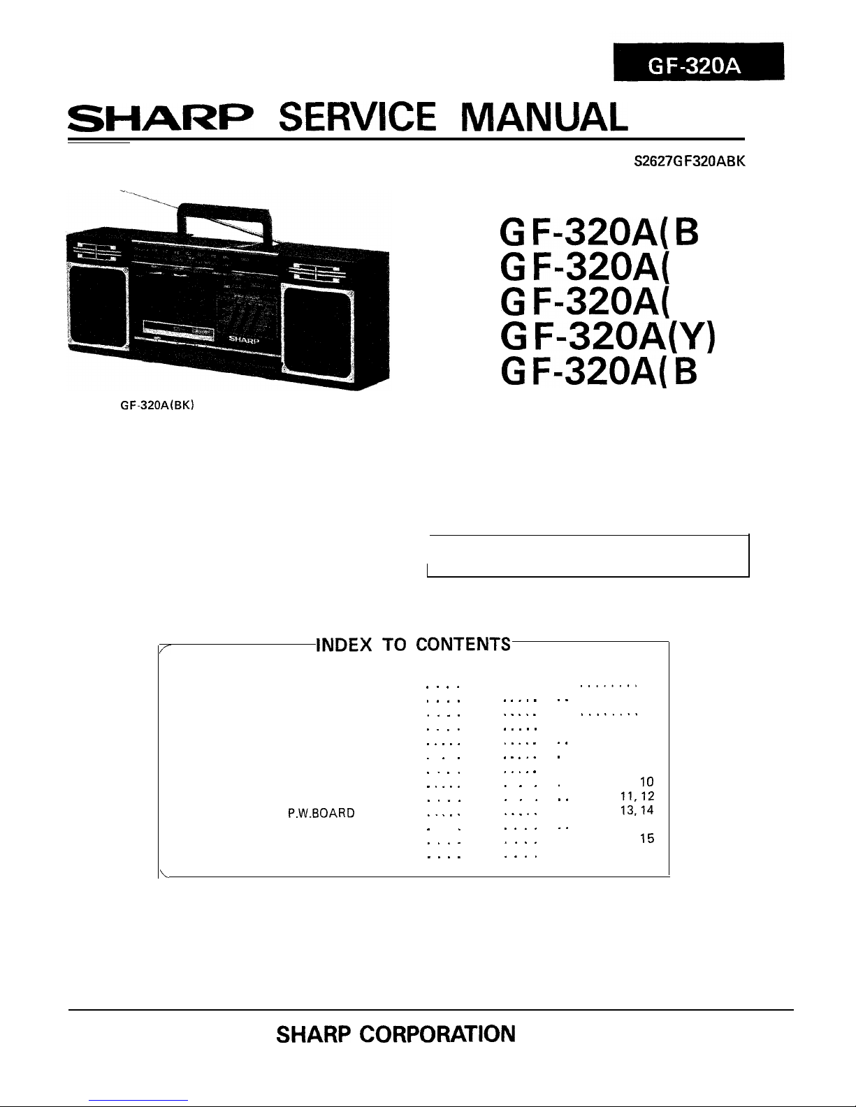
SHARI=
SERVICE
MANUAL
S2627G
F320ABK
G F=320A( B
K)
G F=320A(
R)
G F=320A(
P)
G F-320A(Y)
G F-320A( B
L)
PHOTO:
GF-320A(BK)
in the interests of user-safety the set should be restored to its
original condition and only parts identical to those specified be
used.
/
INDEX
TO CONTENTS
SPECIFICATIONS . . . . . . . . .
STRINGING OF DIAL CORD . . . .
NAMES OF PARTS . . . . . . . , . . .
DISASSEMBLY . . . . . . . . . . . . . .
BLOCK DIAGRAM . . . . . . . . .
CIRCUIT ADJUSTMENT . . . . . . . .
MECHANICAL ADJUSTMENT . . . .
EXPLODED VIEW . . . . . . . . .
SCHEMATIC DIAGRAM . . . . . .
WIRING SIDE OF
P.W.BOARD
. . . .
NOTES ON SCHEMATIC DIAGRAM
TYPES OF TRANSISTOR AND LED
REPLACEMENT PARTS LIST . . . . .
. . , . .
. . . . .
. . . . .
. . . . .
. . . . .
. . . . .
. . .
.
r
.
. . . I .
. . . ,
1 . . .
. . . .
. . . .
\
. . . .
. . . .
. . . .
. . . .
. . . . .
. . .
. . . .
. . . . .
. . . .
. . I . .
.
.
. . . .
Page
. .
........
2
........
2
........
3
........
4
. .
.
.
. .
. .
. . . . . . . .
5
. . . . . .
6-8
. . . . . 8
. . . . .
9,
IO
. . .
II,12
. . . . .
13,14
. . . . . . 15
. . . . . . .
15
. . . . .
16-19
SHARP CORPORATION
Page 2
L
PLEASE REFER TO THE OPERATION MANUAL
GENERAL
Power source:
Output power:
(nput
impedance:
Loaded impedance:
Dimensions:
Weight:
SPECIFICATIONS
AC 240 V, 50 Hz
DC 9 V
(UM/SUM-1
or R20 x 6)
PMPO; 20W (low +
low)
(AC operation)
MPO;
8W
(4W +
4W)
(AC operation)
RMS;
3.8W (1.9W + 1.9W)
(DC operation, 10% distortion)
External mic; 600 ohms
Headphones; 8-25 ohms
External speakers; 4-8 ohms
Width; 494 mm
(19-l/2”)
Height; 180 mm
(7-l/8”)
Depth; 130 mm
(5-l/8”)
2.8 kg (6.2
Ibs.)
without
RADIO
Frequency range:
TAPE RECORDER
Tape:
Frequency response
:
Signal/noise ratio:
Wow and flutter:
SPEAKER
Speakers:
Impedance:
Maximum power
handling capacity:
I
FM; 87.6 - 108 MHz
AM; 526.5 -
1,606.5 kHz
Compact cassette tape
100 Hz - 10,000 Hz
36 dB
0.2% (WRMS)
10 cm
(4”)
woofer x 2
Horn type tweeter x 2
4 ohms
5 W (maximum)
batteries
Specifications for this model are subject to change without
prior notice.
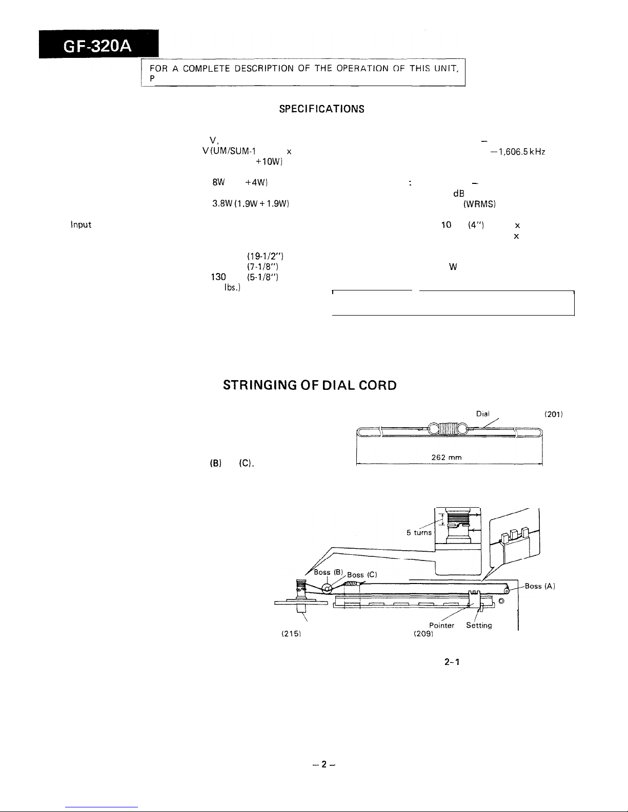
STRINGING OF DIAL
CORD
Dial
Cord Assembly
(201)
1. Wind the dial cord over the tuning control and attach the
tuning control to the front cabinet.
2. Set the dial cord over the boss (A).
3. Set the dial cord over the bosses (B) and
(C).
(A)
Tuning control shaft (Knob)
(215)
Dial
Poind
&kg
Point
/
(209)
Figure 2-
1
-2-
Page 3
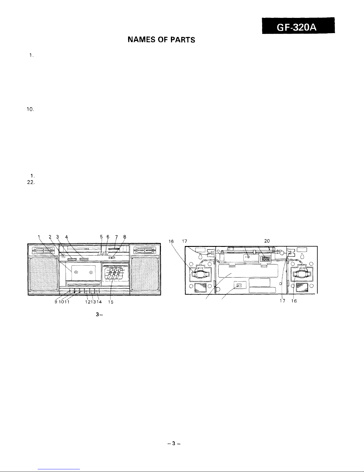
NAMES OF
PARTS
1.
Cassette Compartment
2. Headphone Jack
3. Volume Control
4. Balance Control
5.
Power Indicator
6. FM Stereo indicator
7. Tuning Control
8. Function Selector Switch
9. Record Button
10.
Play Button
11. Rewind Button
12. Fast Forward Button
13. Stop/Eject Button
14. Pause Button
15. Graphic Equalizer Control
16. Speaker Cord Holder
17. Speaker Release Lever
18. External Microphone Jack
19. External Speaker Terminals
20. Telescopic Rod Antenna
2 1.Battery Compartment
22.
AC Power Supply Socket
1
234
56
7 8
7
18
19
20
21 22
17 16
Figure 3- 1
Figure 3-2
-3-
Page 4

DISASSEMBLY
Caution on Disassembly
Follow the
below-mentioned
notes
when
disassembling
the
unit
and reassembling it, to keep its safety and excellent
performance:
1. Take
cassette
out of
the
unit.
2.
Be sure to remove
the power
supply
plug from the wall
outlet before starting to disassemble the unit and remove
the batteries from the unit.
3. Take off nylon bands or wire holders where they need
be
removed
when
disassembling
the
unit.
After
servic-
ing the unit,
be sure to rearrange
the
leads
where they
were
before disassembling.
4. Take sufficient care on static electricity of integrated circuits and other circuits when servicing.
STEP
REMOVAL
PROCEDURE
FIGURE
Main
body section
I
Front Cabinet
1. Battery comparment
lid
..............................
(Atxl
2. Open the cassette
holder
............................
(B)
3. Screw
........................
(C)x5
-
4-l
Mechanism Block
1. Screw
........................
(01x2
2. Socket..
......................
tE)x2
3. Tip
.............................
(F)x2
Main P.W.Board
;. ~,“~o~d;,,,,a,k.~,l,,tbr(G)xl
sprmg.........................
(Hlxl
4-2
-
4-3
Speaker section
/
I
I
1
Front Cabinet
/1.
Screw . . . . . . . . . . . . . . . . . . . . . . . . .
(11x5
4-4
Note:
Set the mechanism in such a way as that the record/playback
selector lever is
positioned as
shown in
Fig.
4-2.
Front Cabinet
Figure 4- 1
Figure 4-4
Record/Playback Selector Lever
\/-----I
$3
x
8mm
Figure 4-2
Figure 4-3
Switch
:/PB Head
(I)
@3 x 25mm
-4-
Page 5
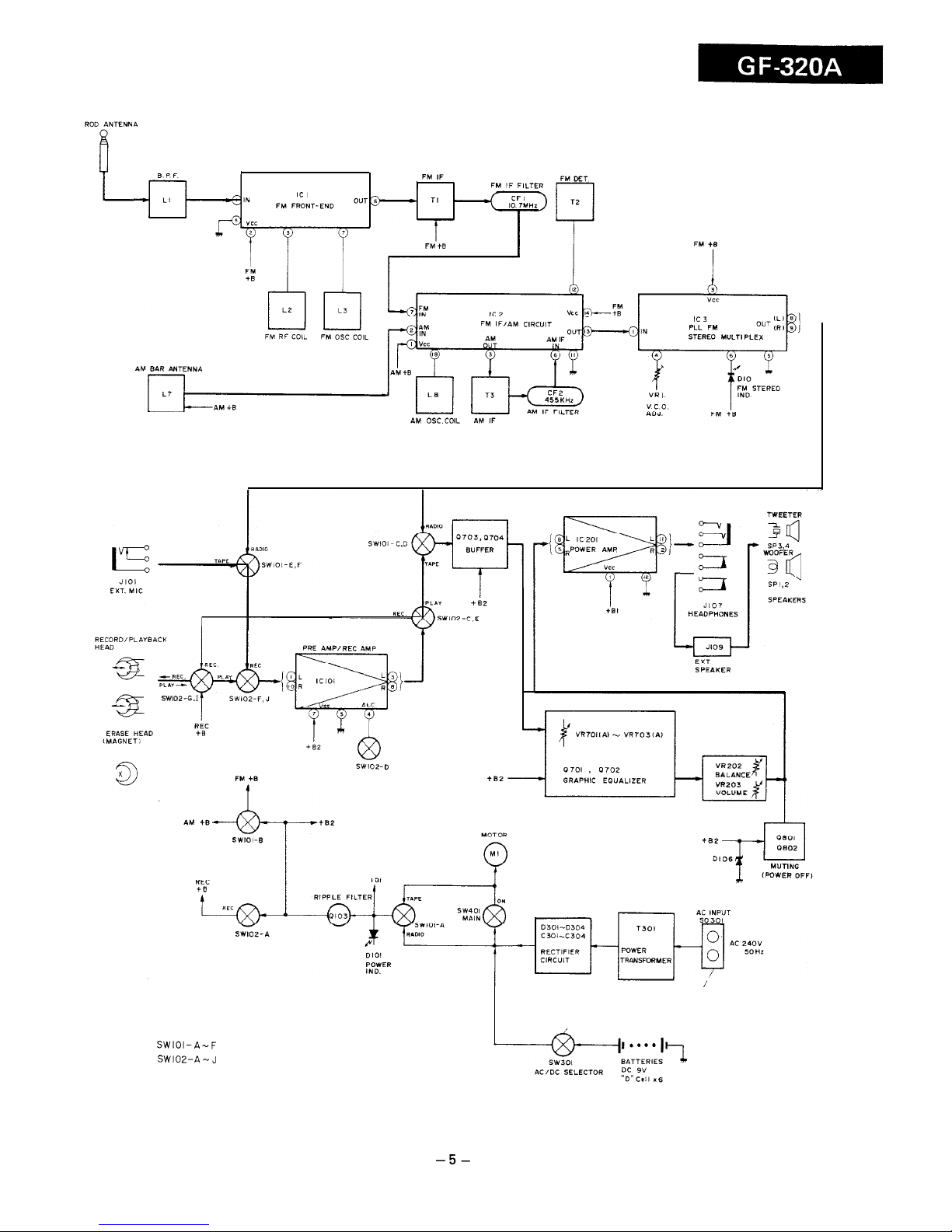
SWIOI-A-F
FUNCTION SELECTOR SWITCH
SWIOZ-A-J
RECORD/PLAYBACK SWITCH
Figure 5 BLOCK DIAGRAM
-5-
Page 6
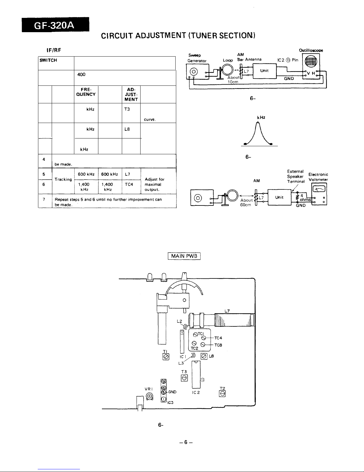
CIRCU
IT ADJUSTMENT
(TUNER SECTION
AM
IF/RF
ADJUSTMENT
Ckcilloscope
Test AM
-
.
SWITCH
POSITION
AM
SIGNAL
400
Hz, 30%. AM modulated
GENERATOR
TEST
FRE- DIAL
AD-
STEP STAGE
QUENCY POINTER
JUST-
REMARKS
SETTING MENT
1
IF
455 kHz
High
T3
Adjust for
frequency best “IF”
cu we.
2
510
kliz
Lowest L8
Band
frequency
Adjust for
-
coverage
maximal
3
1,650
Highest
TC8 output.
kHz frequency
Repeat steps 2 and 3 until no further improvement can
Figure 6- 1 AM IF
455
kHz
A
Figure 6- 2 AM IF CURVE
Signal
Generator
Test
Loop
Bar Antenna
Figure 6-3 AM RF
Figure 6- 4 ADJUSTMENT POINTS
-6-
Page 7

FM IF/RF ADJUSTMENT
10.7 MHz
Oscilloscope
FM mono
I
WITCH
?OSITION
SIGNAL
GENERATOR
400 Hz, 30%. FM modulated.
-
;TEP
I 1
I 1
TEST
STAGE
ADJUST-
MENT
Tl
REMARKS
1. Using a
minus
driver, turn
the core of
T2
counter-
clockwise
before taking
it out of the
bobbin.
2. Adjust for
best
“IF”
curve.
Adjust for best
“S” curve.
Figure 7-l FM IF
-Y- -%f
1
IF
10
.7
MHz High
frequency
Figure 7-2 IF CURVE
Figure 7-3 FM S CURVE
Detection
T2
Electronic
Repeat steps 1 and 2 until no further improvement can
/
1
FM
Signal
External
Voltmeter
Rod Antenna
Generator
Speaker
t
1
I~
,( Terminal
‘I
Unit
be made.
Band
frequency
coverage
109 MHz
Highest
TC2
maximal output.
1
frequency
Repeat steps 4 and 5 until no further improvement can
be made.
88 MHz
88MHz
L2 Adjust for
Trackmg maximal
108 MHz 108 MHz
TCl
output.
Repeat steps 7 and 8 until no further improvement can
be made.
5
Dummy
(See Figure
7-6)
6
-
7
Figure 74 FM RF
Electronic
B
FM
Signal
Generator
Rod Antenna
I
9
7
VCO FREQUENCY ADJUSTMENT
Dummy
(See
Figure
7-6)
GN/D
SIGNAL
I
400 Hz, 30%. FM modulated
GENERATOR
(mono signal)
I
Figure 7-5 VCO FREQUENCY
A
To Telescopic Rod Antenna
R2
FM mono position
98 MHz at
98 MHz
60 dB
FM stereo position (unmodulated)
VRl
Adjust for
38.00
kHz
+ 100 Hz.
To Chassis
GND
Rl =
500hms
z =
5o
OhmsLR2 =
5.
ohms
2:
Output impedance of signal generator
Figure 7-6 FM DUMMY
-7-
Page 8

CIRCUIT ADJUSTMENT (AUDIO
SECTION)
SETTING
. Volume control. Maximum
POSITION
l
Graphic
equalrzer
control: Center
OF SWITCH
l
Balance control. Center
AND KNOB
l
Function selector
switch:
Tape
ITEM INPUT
ADJUST-
MENT
REMARKS (CHECK)
POINT
PLAY BACK
Test tape
(1.2 V *3
dB)
AMPLIFIER
MTT-118
__
SENSITIVITY
ITEM
JIG
Driving
power
-
z&fjq
Torque
Torque
meter
Play TW-2111
Fast-forward
TW-223 1
Rewind
TW-223 1
Azimuth
Tape
speed
1
ADJUSTMENT
POINTS
I
Test Tape
MTT-113C
Azimuth
adjusting screw
External
Oscilloscope
Test Tape
MTT-118
Head
Figure
8-
1
PLAYBACK AMPLIFIER SENSITIVITY
MECHANICAL ADJUSTMENT
Ruba3Ks (CHECK)
(More than 140
g)
(Play:
30 - 60
g-m)
(Fast-forward:
55 -
IlOgcm)
(Rewind:
55- 1lOgcm)
Sine waveform
attains the
maximum.
3,000
*90
Hz
Test
1
MTT-1
E.V:
ELECTRONIC VOLTMETER
Dual-trace
External
Svncroscope
‘ape
13C
Head
Figure
8-2
AZIMUTH
External
Speaker
Test Tape
MTT-111
, Record/Playback
Head
Figure 8- 3
TAPE SPEED
-8-
Page 9

1
I
2
I
3
I
4
I
5
I
6
63
I
44,
&,.49 ]
57x3
;c.
v5
73
60mm
103
Page 10

-‘\,-&
/’
<
‘1
‘.
203
/204(LEFT)
205fRIGHTl
/ii&
214x6
605
/
GRAPHIC
EOALIZER PWB-B /
‘“T
@
238
21
Figure 10 CABINET EXPLODED VIEW
- 10 -
.
-,_
--- ._.. ---..---.._--
-__. -... -~__--_---
I__.
-III--2
.---_..
_ I
Page 11

0103 290655 E
RIPPLE FILTER
l
NOTES ON SCHEMATIC DIAGRAM can be found on page 15.
1
I
2
I
3
I
4
I
5
I
6
Figure 11
SCM
-ll-
Page 12

I
MAIN
PWB-Al
-
I
l
c44
Ill25”
P701, 0702
ZSCl815
GR
GRAPHIC
EQUALIZEF
a703,0704
X:2;;
GR
J III
I
I
<----J
/
POWER SUPP
LY
PWR-A,/
I
7
I
8
I
8
I
10
I
11
I
12
1
SCHEMATIC
DIAGRAM
-12-
Page 13

I
1
I
2
1
3
I
4
I
5
I
6
Figure 13 WlRiNG
Sir
Page 14

7
I
8
I
9
1
IO
I
II
I
I2
GRAPHIC EQUALIZER PW B -
B
I
7
I
8
I
9
I
IO
I
II
I
I2
3
SIDE OF
P.W.BOARD
- I4 -
Page 15

NOTES ON SCHEMATIC
DIAGRAM
l
Resistor:
To differentiate the units of resistors, such symbol K and
M are used: the symbol K means 1000 ohm and the symbol
M means 1000 kohm and the resistor without any symbol is
ohm-type resistor. Besides, the one with “Fusible” is a fuse
type.
0
Capacitor:
To indicate the unit of capacitor, a symbol P is used: this
symbol P means micro-micro-farad and the unit of the
capacitor without such a symbol is microfarad. As to electrolytic capacitor, the expression “capacitance/withstand
voltage” is used.
(CH), (TH), (RH), (UJ): Temperature compensation
2SC1815
GR
250655 E
E C
8
000
0
l
The indicated voltage in each section is the one measured
by Digital
Multimeter
between such a section and the
chassis with no signal given.
(
): AM mode
Marking except
for
(
):
FM
mode
. Schematic diagram and Wiring Side of P.W.Board for this
model are subject to change for improvement without
prior notice.
l
Parts marked with
” f!L ” (’ )
are important for maintaining the safety of the set. Be sure to replace these parts
with
specified
ones for maintaining the safety and perfor-
mance of the set.
GL5PA6061F
Figure 15 TYPES OF TRANSISTORS AND LED
-15-
Page 16

Ll
e
REPLACEMENT PARTS LIST
“HOW TO ORDER REPLACEMENT PARTS”
S
t
To have your order filled promptly and correctly, please furnish the following information.
1. MODEL NUMBER
2.
REF. NO.
3. PART NO.
4. DESCRIPTION
I-
S
‘_
NOTE:
Parts marked with
“A”
are important for maintaining the safety of the set.
Be sure to replace these parts with
specified ones for maintaining the safety and performance of the set.
REF.NO.
ICI
IC2
IC3
ICl 01
IC201
Q103
Q701
0702
0703
Q704
Q801
Q802
Dl
03
D4
D5
D6
D7
DlO
DlOl
D102
D103
D106
A
D301
A D302
8
D303
8 0304
Ll
I2
L3
LJ
L8
Tl
T2
T3
bT301
CFl
CF2
PART NO.
DESCRIFTION
CODE
REF.NO.
PART NO.
DESCRIPTION
CODE
INTEGRATED CIRCUITS
CONTROLS
VHiTA7335P/-I
VH
iAN7224//- 1
VHiTA7343P/-1
VHiM51164Y-1
VHiBA5406//-1
FM Front-End, TA733.5
P
FM IF/AM Circuit, AN7224
PLL FM Stereo Multiplex,
TA7343
P
Pre Amp., M51
164L
Power Amp.,
8A5406
AG
AH
AG
AG
AU
TRANSISTORS
VS2 SD655
E/l-
1
Silicon,
NPN,
2SD655 E
VS2SC1815GR-1
Silicon, NPN,
2SC1815 GR
VS2SC1815GR-1
Silicon, NPN.
2SC1815 GR
VS2SC1815GR-1
Silicon, NPN,
2SC1815 GR
VS2SC1815GR-1
Silicon, NPN,
2SC1815 GR
VS2SC1815GR-1
Silicon. NPN.
2SC1815 GR
VS2SC1815GR-1
Silicon. NPN,
2SC1815 GR
AC
AB
AB
A8
AB
AB
AB
VCl -4
RVC-R0085AFZZ
Variable Capacitors, Tuning
with Trimmers:
TCl:
FM RF Trimmer
TC2; FM Oscillator Trimmer
TC4; AM Antenna Trimmer
TC8; AM Oscillator Trimmer
VRl RVR-M0390AFZZ
5 kohms(B)
VR202
92LVR-523A
50 kohms (G)
VR203(A,B) 92LVR-523B
20 kohms (U)
VR701-703 RVR-Q0207AFZZ
100 kohm (B)
ELECTROLYTIC CAPACITORS
[All
electrolytic capacitors are
+20%
type.)
DIODES
VHDl SSI 33//-l
Silicon, 1
SS133
VHDl SS133//-1
Silicon, 1
SS133
VHDl SS133//-1
Silicon, 1
SS133
VHDI SS133//-1
Silicon, 1
SSI
33
VHDl SS133//-1
Silicon, 1 SS133
VHDl SS133//-1
Silicon, 1
SS133
VHPGffiPR6061 F
LEO, Red,
GffiPR6061 F
VHPGL5PR6061 F
LED, Red,
GL5PR6061 F
VHERDGR8JB2-1
Zener,
6.8V, RD6.8JB2
VHDl SS133//-1
Silicon, 1 SS133
VHERDSRl
JB2-1
Zener, 5.1 V, RD5.1 JB2
VHDS5566G//-1
Silicon,
S5566G
VHDS5566G//-1
Silicon,
S5566G
VHDS5566G//-1
Silicon.
S5566G
VHDS5566G//-1
Silicon,
S5566G
AA
AA
AA
AA
AA
AA
AC
AC
AB
AA
AA
AB
AB
AB
AB
COILS
RCiLA0652AFZZ
FM Band Pass Filter
92LCdiLR-197A
FM RF
92LCijiL&158A
FM Oscillator
RCilAO796AFZZ
AM Bar Antenna
92LCbiL&200A
AM Oscillator
TRANSFORMERS
AD
AA
AA
AH
AC
92LiFT-258A
FM IF
92LiFT-1 97A
FM Detector
92LiFT-523A
AM IF
92LPT-531
A Power
FILTERS
AC
AC
AC
AT
RFiLFO080AFZZ
Ceramic, FM IF 10.7
MHz
RFiLA0057AFZZ
Ceramic, AM IF, 455 kHz
AD
AD
Cl 2
Cl 5
c20
C25
C26
c40
c41
C42
c44
c47
C48
c49
c74
c75
Cl13
Cl14
Cl 17
Cl 18
Cl19
Cl20
Cl 21
Cl25
Cl26
Cl 34
Cl 42
C207
C2OB
c211
c212
C213
C214
C215
C216
c219
c220
c221
C223
C224
C727
C728
RC-EZA476AFl
A
RC-EZAI
06AFl C
RC-EZA476AFl
A
RC-EZA107AFl
A
RC-EZA475AFl E
RC-EZA106AFl C
RC-EZA335AFl E
RC-EZAI
05AFl H
RC-EZA475AFl E
RC-EZA105AFl H
RC-EZA105AFl H
RC-EZA227AFl
A
RC-EZAI
06AFl C
RC-EZA476AFl
A
RC-EZA107AFl
A
RC-EZA107AFl
A
RC-EZA335AFl E
RC-EZA335AFl E
RC- EZA106AFl C
RCGZA477AF0J
RC-
EZA476AFl
A
RC-EZAI
07AFl
A
RC-EZAl06AFl C
RC-EZA476AFl C
RC-EZA226AFl C
RC-EZA105AFl H
RC-EZA105AFl H
RC- EZA336AFl C
RC-EZA336AFl C
RC-EZA476AFl
A
RC-GZA337AFl C
RC-EZA476AFl
A
RC-EZA476AFl
A
RC-EZA227AFl
A
RC-EZA227AFl
A
RC-GZV228AFl C
RC-EZA224AFl H
RC-
EZA224AFt H
RC-EZAl05AFl H
RCEZAl05AFl H
47
/.LF, 1OV
10
pF,
16V
47
/LF, 1OV
100
pF,
1OV
4.7
,u.F, 25V
10
pF,
16V
3.3
/LF,
25V
1
P-F.
50V
4.7
pF,
25V
1 PF, 50V
1 PF, 50V
220
pF,
1OV
10
pF,
16V
47
pF,
1OV
100
pF, IOV
100
,uF, IOV
3.3
@F,
25V
3.3
pF,
25V
10
~.LF,
16V
470
~.LF, 6.3V
47
pF,
1OV
100
pF, IOV
10
/LF,
16V
47 PF. 16V
22
,uF. 16V
1
pF,
50V
1 PF, 50V
33
/LF,
16V
33
pF,
16V
47
pF,
1OV
330
pF,
16V
47
pF, 1OV
47
pF,
1OV
220
pF,
1OV
220
P-F, IOV
2200
pF,
16V
0.22
P-F,
50V
0.22
,I.LF, 50V
1 /LF.
50V
1
PF, 50V
- 16-
AL
AB
AD
AF
AE
AB
AB
AB
AB
AB
AB
AB
AB
AB
AB
AB
AB
AB
AB
AB
AB
AB
AB
AB
AB
AB
A8
A8
AB
AG
AB
AB
AB
AB
AB
AC
AB
AB
A8
AB
AE
AB
AB
AB
AB
Page 17

REF.NO.
PART NO. DESCRIPTION
CODE
C729 RC-EZA476AFl C
47
pF,
16V
AB
c731
RC-EZAI
05AFl H
1
pF,
50V
AB
C732
RC-EZAl05AFl H
1
pF,
50V
AB
c733
FiGEZA335AFl E
3.3
,uF.
25V
AB
c734
RC-EZA335AFl E
3.3
/LF,
25V AB
C801
RC-EZA475AFl E
4.7
PF.
25V
A0
CAPACITORS
There
are two types of
capacitors
available and they can be Identified from each
other by
reading their
Part Numbers.
l
Ceramic type capacitor:
Asymbol”C” or”K” IS givenat the3rd dlgitof
its Part Number
like”VCC(or
K).**.**.J.”
0 Semiconductor type
capacitor;
Asymbol”T’
is
gwen
at
the3rd digitof
its
PartNumberiike”VCTo.....
l
J.”
The
capacitance error of each capacttor is Indicated by the symbol given at the
13th digit of the Part Number as
follows:“~’ (*5%). “K” (&lo%), “M” (&ZO%),
“N” (f30%), “C”
(f0.25
pF).
“D” j&O.5
pF), “T’ (+80-20%).
(Tubular type ceramic-capacnor is Identitled by the symbol MF of the part No.
VCOOMFOOOOOOO;
this MF does not mean the lead
wire.)
Cl
c2
c3
c4
C6
c7
C8
c9
Cl3
Cl4
Cl 9
c21
c22
C23
C24
C29
c30
c43
c45
C46
c73
c77
Cl 03
Cl04
Cl 05
Cl
06
Cl 07
Cl 08
Cl 11
Cl 12
Cl 22
Cl 24
Cl 29
Cl 30
Cl 31
Cl 32
Cl 37
Cl38
Cl 41
C209
c210
c217
C218
c222
c301
C302
c303
c304
VCCSBTl H
L18OJ 18
pF.
50V
VCTYMFl HV472K
0.0047
pF,
50V
VCTYMFI
HV472K
0.0047
pF,
50V
VCCCMFl HH220J
22 pF(CH), 50V
VCCRMFI HH220J
22
pF(
RH), 50V
VCCCPUl HH330J
33 pF(CH), 50V
VCCCMFl HH3R9C
3.9 pF(CH), 50V
VCTYMFl
HV472K
0.0047
pF,
50V
VCTYMFl
CY223N 0.022 pF,
16V
VCTYMFlCY223N 0.022
f*F,
16V
VCTYMFI
EXlO3N
0.01
pF,
25V
VCTYMFI
CY223N 0.022 pF,
16V
VCTYMFl CY223N 0.022 pF,
16V
VCKYMFl HB221 K 220
pF,
50V
VCTYMFl
CY223 N
0.022 pF, 16V
VCTYMFl
CY223N 0.022 pF, 16V
VCTYMFI
CY223N 0.022 ,uF.
16V
VCQSMAl HLI 02J 0.001 ,u.F, 5OV. Styrol
VCTYMFl
NY333N 0.033 pF,
12V
VCTYMFl
NY333N 0.033 pF,
12V
VCTYMFl
CY223N 0.022 pF, 16V
VCCRMFI HH6R8D
6.8 pF(RH), 50V
VCCSMFl HLIOI J100 pF,
50V
VCCSMFI
HLl 01 J100
pF,
50V
VCKYMFl HB102K
0.001
pF,
50V
VCKYMFl
HB102K 0.001 pF,
50V
VCTYMFl
HV152K
0.0015
pF,
50V
VCTYMFl HVI
52K 0.0015
pF,
50V
VCTYPAl EX683K 0.068 /LF,
25V
VCTYPAl EX683K 0.068 ,oF,
25V
VCTYMFI
EX103N
0.01
,tcF,
25V
VCTYMFlCY223N 0.022 pF,
16V
VCKYMFI HB821 K 820
pF,
50V
VCKYMFl
HB821 K 820
pF,
50V
VCCSMFl HL470J
47
pF,
50V
VCCSMFl HL470J
47
pF,
50V
VCTYMFl
CY223N 0.022
PF. 16V
VCTYATl CY223N 0.022
PF.
16V
VCNBTl CY103N
0.01
pF,
16V
VCKYMFI
HBl02K 0.001 ELF,
50V
VCKYMFl
HB102K 0.001
PF. 50V
VCTYPAl EX104K
0.1
pF,
25V
VCTYPAl
EXI 04K 0.1 FF, 25V
VCTYPAI
EXI 52K 0.0015
pF, 25V
VCKZPAl HF103Z
0.01
pF,
50V
VCKZPAI HF103Z
0.01
pF,
50V
VCKZPAl HFl03Z
0.01
pF,
50V
VCKZPAl HF103Z
0.01
,uF,
50V
AA
AA
AA
AA
AA
AA
AA
AA
AA
AA
AA
AA
AA
AA
AA
AA
AA
AB
AA
AA
AA
AA
AA
AA
AA
AA
AA
AA
AA
AA
AA
AA
AA
AA
AA
AA
AA
AA
AA
AA
AA
AB
AB
AA
AA
AA
AA
AA
-
Ii
I-
REF.NO.
PART NO. DESCRIPTION
CODE
c701
VCTYMFl EX822K
0.0082
pF,
25V
AA
C702
VCTYMFl EX822K
0.0082
pF,
25V
AA
c707
VCKYMFl HB102K 0.001
PF. 50V
AA
C708
VCKYMFl
HB102K 0.001
PF. 50V
AA
c711
VCKYMFl
HB561 K 560
pF,
50V
AA
C712
VCKYMFI HB561 K 560
pF,
50V
AA
c715
VCTYMFl
CY223M 0.022 pF, 16V
AA
C716
VCTYMFl
CY223M 0.022 pF, 16V
AA
C721
VCTYMFI
EX822K
0.0082
pF,
25V
AA
C722 VCTYMFI
EX822K
0.0082
FF.
25V
AA
C725,726
VCTYMFl HVl52K
0.0015
pF,
50V
AA
RESISTORS
(Unless othenwse specified, resistors are
f5%,
carbon type.)
(Tubular type carbon film resistor
&5%
is identified the symbol MF of the part
No. VRD-MFOOOOOOO: this MF does not mean lead wire.)
VRPMF2EEOOOC
0 ohm,
1/4W, kO.25
ohms, AA
Rl
R4
R5
R6
R7
R8
R9
RIO
Rl
1
R41
R42
R43
R44
R45
R46
R47
R48
R49
R51
R63
R65
R105
R109
RllO
Rll
1
R112
RI 13
R114
R117
R118
R125
Rl26
R127
R128
RI 29
R130
R134
R135
RI 43
RI44
RI47
R149
RI 50
R153
R154
R201
R202
R203
R204
R207
R208
VRDST2CD681 J
VRDMF2EE824J
VRDST2CD562J
VRDMF2EE822J
VRDMF2EE272J
VRDST2CD680J
VRDST2CD471 J
VRDMF2EE152J
VRDMF2EE471 J
VRDST2CD102J
VRDMF2EE103J
VRDST2CD224J
VRDMF2EE471 J
VRDST2CD332J
VRDST2CD332J
VRD-ST2CDl02J
VRDMF2EElO2J
VRDMF2EElOl J
VRDST2CD471 J
VRDMF2EE470J
VRD MF2EElOl J
VRPMF2EE182J
VRDST2CD822J
VRDMF2EE822J
VRDST2CDlOl J
VRDMF2EElOl J
VRDMF2EE222J
VRDST2CD222J
VRDMF2EE123J
VRDMF2EE123J
VRD-ST2CD15OJ
VRDST2CD15OJ
VRDST2CDl82J
VRD-
MF2EE182J
VRDST2CD473J
VRDMF2EE473J
VRDMF2EE122J
VRDMF2EE222J
VRDMF2EE473J
VRDMF2EE473J
VRDST2CD125J
VRDMF2EE333J
VRDMF2EE102J
VRDMF2EE393J
VRDMF2EE393J
VRD-MFZEEI
82J
VRDMF2EE182J
VRD-
MF2EE332J
VRDMF2EE332J
VRD-MF2EE221 J
VRDMF2EE221 J
Jumper
680 ohms,
1/6W
820 kohms,
l/4W
5.6 kohms,
1/6W
8.2 kohms.
1/4W
2.7 kohms,
1/4W
68 ohms,
1/6W
470 ohms,
1/6W
1.5 kohms,
1/4W
470 ohms,
1/4W
1 kohm.
1/6W
10 kohm,
1/4W
220 kohms.
1/6W
470 ohms,
1/4W
3.3 kohms.
1/6W
3.3 kohms,
1/6W
1 kohm,
1/6W
1 kohm,
1/4W
100
ohm,
1/4W
470 ohms,
1/6W
47 ohms,
1/4W
100 ohm,
1/4W
1.8 kohms,
1/4W
8.2 kohms,
1/6W
8.2 kohms.
1/4W
100
ohm,
1/6W
100 ohm,
1/4W
2.2 kohms,
1/4W
2.2 kohms,
1/6W
12
kohms,
1/4W
12 kohms,
1/4W
15 ohms,
1/6W
15 ohms,
1/6W
1.8 kohms.
1/6W
1.8 kohms,
1/4W
47 kohms,
1/6W
47 kohms,
1/4W
1.2 kohms,
1/4W
2.2 kohms,
1/4W
47 kohms,
1/4W
47 kohms.
1/4W
1.2 Mohms,
1/6W
33 kohms,
1/4W
1 kohm.
1/4W
39 kohms,
1/4W
39 kohms,
1/4W
1.8 kohms,
1/4W
1.8 kohms,
114W
3.3 kohms,
1/4W
3.3 kohms,
1/4W
220 ohms,
1/4W
220 ohms,
1/4W
AA
AA
AA
AA
AA
AA
AA
AA
AA
AA
AA
AA
AA
AA
AA
AA
AA
AA
AA
AA
AA
AA
AA
AA
AA
AA
AA
AA
AA
AA
AA
AA
AA
AA
AA
AA
AA
AA
AA
AA
AA
AA
AA
AA
AA
AA
AA
AA
AA
AA
AA
Page 18

REF.NO.
I3209
R210
R211
R212
R213
R214
R601
R602
R701
R702
R703
R704
R707
R708
R715
R716
R717
R718
R719
R720
R727
R728
R729
R730
R731
R732
R733
R734
R735
R736
R737
R738
R739
R741
R742
R745
R746
R801
R802
PART NO.
DESCRIPTION
VRDST2CD2R2J
2.2 ohms, 1
J6W
VRDST2CD2R2J
2.2 ohms,
1/6W
VRDMF2EE151
J
150 ohms,
1/4W
VRDMF2EE151
J
150
ohms,
1/4W
VRDMF2EE332J
3.3 kohms,
1/4W
VRDMF2EE332J
3.3 kohms,
1/4W
VRDSTZCD473J
47 kohms,
1/6W
VRDST2CD473J
47 kohms,
1/6W
VRDMF2EE473J
47 kohms,
1/4W
VRDMF2EE473J
47 kohms,
1/4W
VRDMF2EE473J
47 kohms,
1/4W
VRDMF2EE473J
47 kohms,
1/4W
VRDMF2EE272J
2.7 kohms,
1/4W
VRDMF2EE272.l
2.7 kohms,
1/4W
VRDMF2EE223J
22 kohms,
1/4W
VRDMF2EE223J
22 kohms,
1/4W
VRDMF2EE223J
22 kohms,
1/4W
VRDMF2EE223J
22 kohms,
1/4W
VRDMF2EE153J
15 kohms,
1/4W
VRDMF2EEl53J
15 kohms,
1/4W
VRDMF2EE123J
12 kohms,
1/4W
VRDMF2EEl23J
12 kohms,
1/4W
VRDMF2EEl23J
12 kohms,
1/4W
VRDMF2EEl23J
12 kohms,
1/4W
VRDMF2EE271
J
270 ohms,
1/4W
VRDMF2EE271
J
270 ohms,
1/4W
VRDST2CD392J
3.9 kohms,
1/6W
VRDST2CD392J
3.9 kohms,
1/6W
VRDMF2EE684J
680 kohms,
1/4W
VRDMF2EE684J
680 kohms,
1/4W
VRDMF2EEl22J
1.2 kohms,
1/4W
VRDMF2EE122J
1.2 kohms,
1/4W
VRDST2CD221 J
220 ohms,
1/6W
VRDMF2EE824J
820 kohms,
1/4W
VRDMF2EE824J
820 kohms,
114W
VRDMF2EE561
J 560 ohms,
1/4W
VRDMF2EE561
J
560 ohms,
1/4W
VRDST2CD472J
4.7 kohms,
1/6W
VRDST2CD472J
4.7 kohms,
1/6W
CODE
REF.NO.
PART NO.
DESCRIPTION CODE
AA
AA
AA
AA
AA
AA
AA
AA
AA
AA
AA
AA
AA
AA
AA
AA
AA
AA
AA
AA
AA
AA
AA
AA
AA
AA
AA
AA
AA
AA
AA
AA
AA
AA
AA
AA
AA
AA
AA
CIRCUIT PARTS
CNSlOl
CNS102
CNPlOl
CNP102
Jl
01
JlO7
JlO9
Ml
8 so301
QCNWN0005AFZZ
Connector Assembly, 3Pin
QCNWN0006AFZZ
Connector Assembly,
3Pin
QCNCMI
36CAFZZ Plug, 3 Pin
QCNCMl36CAFZZ
Plug,
3Pin
QJAKEO157AFZZ
Jack External Microphone
QJAKJOl64AFZZ
Jack Headphones
QTANZOBOBAFZZ Terminal, External Speaker
RM5TV0235AFOl
Motor, Assembly
QSdCE0596AFZZ
Socket,
AC/DC
Power
Supply (with AC/DC
Selector Switch)
92LSP-523A
Speaker, Woofer
RALMB0057AFZZ
Speaker, Ceramic Tweeter
QSW-BO212AFZZ
Switch, Slide Type
QSW-SO512AFZZ
Switch,
Slide
Type
94RMSW-1541
ACV Switch, Leaf Type
AD
AC
AB
AB
A8
AE
AE
AT
AH
SPl.2
SP3.4
SW1 01
SW1
02
SW401
AM
AC
AH
AF
AD
MECHANICAL PARTS
83
94R98880000
1
94R18210160
Main Chassis
-
2
94R18210167
Switch Plate
AC
3
94R182107
501 Push Button Actuator Ass’y AD
4
94R18210128A
Lever, Record Button
AC
5
94R18210129
Lever, Play Button AC
6
94R18210130
Lever, Rewind Button AC
7
94R18210131
Lever, Fast Forward Button
AC
8
94R18210132
Lever, Stop Button
AC
9
94R182101503
Lever Ass’y, Pause Button AD
10
94R18210168
11
94R18210115
12
94R18210116
13
94Rl8210134
14
94Rl8210123
15
94Rl8210119
16
94R18210124
17
94R18210150
18
94R18210138
19
94R18210122
20
94R18210162
21
94R18210121
22
94Rl8210113
24
94Rt
8290110
25
94Rl8210306
26
94R18210310
27
94R18210302
28
94R182903301
30
94R18210312
31
94R18210305
33
94R18211305
34
94R18210307
35
94R182104301
36
94R18210408
37
94Rl8213912
39
94R182107302
40
94R18210704
4!
94R18670405
42
94Rl8210703
44
94R182109301
45
94R182910501
A
46
94R182110503
47
94Rl8670310
48
94R18211008
49
94R18670309
50
94R18211012
51
94R182110301
52
94 RI 82910302
53
94 RI 8000201
54
94R18000517
55
94R18211212
56
94Rl8201306
57
94R18211202
59
94 RI 7200905
62
94R18211304
63
94R18211311
64
94R18291001
66
RHEDHO152AFZZ
67
RHEDZ0060AFZZ
70
94R90760000
71
94
R91800000
73
94R96790000
Lever, Rewind AC
Lever, Pause
AC
Spring, Pause Lever
AB
Stopper, Pause
AA
Spring,
Button Lever
AB
Sub-Chassis AD
Spring. Button Lever AB
Spring, Play Button Lever AB
Spring,
Switch Actuator AC
Spring, Actuator AB
Lever, Auto
AC
Sprtng,
Auto Lever AB
Spring,
Button Lever AB
PR
Stopper
AC
Spring,
MG Arm AB
Head Panel
AD
Head Base AC
Sensing Plate Ass’y
AD
Spring, Head Panel
AB
MG Arm
AC
Screw, P.M.
E.
AA
Spring,
Azrmuth
AB
Pinch Roller Arm Ass’y
AG
Spring, Pinch Roller
AS
MS Screw
AC
RF Pulley Arm Ass’y
AH
Spring, RF Pulley Arm
AB
Caller, Arm
AB
RF Belt
AG
Flywheel Ass’y
AK
Reel Base Ass’y
AG
Take-Up Gear Plate Ass’y
AD
Gear, Take-Up Roller
AB
Plate Spring,
T.G.
AB
Gear, Fast Forward
AB
Spring, Back Tension
AB
Supply Reel Ass’y
AF
Take-Up Reel
Ass’y
AF
Lever, Record Safety
AC
Spring, Back Tension
AB
Bracket, Motor
AE
Rubber, Motor
AA
Screw, Motor
Caller
AA
Belt, Main
AG
Lever, Eject Slide
AC
Spring,
Eject
Slide Lever
A8
Plate Spring, Pack
AC
Head,
Record/PIayback
AM
Head, Erase
AG
AA
AA
AA
74
94R97650000
75
94 R90040000
77
94R98200000
78
94R99220000
82
94
R94210000
Tams Screw, @2 X
3mm
Tapping Screw, 42 X
4mm
Tapping Bind Screw, $2 X
5mm
Screw,
Q1.7
X
4mm
Screw, @2 X
6mm
Screw, (p2 X
7mm
Screw, Azimuth
Washer,
$1.2
X
$13
X
0.25mm
Washer,
$1.2
X @3 X
0.4mm
AA
AA
AA
AA
AA
AA
84
94R98750000
Washer,
$1.55 X G3.8
X AA
85
94R99370000
0.5mm
Washer,
gj2.05 X 94 X
0.4mm
Lever, Operation
Frame
Shaft, Button Lever
Screw, $2 X
7mm
Screw, $2 X
5mm
AA
87
94R18213107
88
94R18213106’
89
94R18293103
90
94R99820000
96
94R91810000
AC
AF
AD
AA
AA
-
18
-
Page 19

REF.NO. PART NO.
DESCRIPTION
CODE
101
LANGTl397AFZZ
Bracket, Button Lever Shaft AB
102
92LMANG523A
Bracket, Record
AB
103 LHLDWI 075AFZZ
Nylon Band
AA
CABI
NET
PARTS
201 CSPRTI
206AFO2
Dial Cord Assembly
AD
202
92LCAB523FFiTOl
Front Cabinet Assembly. (BK) AV
202
92LCAB571 FRTOI
Front Cabinet Assembly, (R) AV
202
92LCAB572FRTOl
Front
Cabrnet
Assembly, (P) AV
202
92LCAB573FRTOl
Front Cabinet
Assemblv, in
AV
202
92LCAB574FRTOl
Front Cabinet Assembly,
(BL) AV
202-l
Front Cabinet, (BK)
202-l
202-I
202-I
202-I
202-2
202-3
202-3
202-3
202-3
202-3
202-4
202-5
203
203
203
203
203
204
204
204
204
205
205
205
205
206
206
206
206
206
207
izz--
208
92LLiD523A-BK
208
92LLiD571
A-RD
208
92LLiD572A-PK
208
92LLiD573A-YW
208
92LLiD574A-BL
209
92LPiNT523A
210
92LHNDL523A-BK
Front Cabinet, (R)
-
Front Cabinet, (P)
-
Front Cabinet,
(Y)
-
Front Cabinet, (BL)
-
92LPANEL523A
Operation Plate
AK
HDECAOGI
SAFSA
Decoration Plate, Graphic AG
Equalizer, (BK)
HDECAOGI SAFSE Decoration Plate, Graphic
Equairzer,
(R)
AG
HDECAOGI SAFSB Decoration Plate, Graphic
Equalizer, (P)
AG
HDECAOGI SAFSD Decoration Plate, Graphic
Equalizer,
(Y)
AG
HDECAOGI SAFSC Decoration Plate, Graphic
AG
Equalizer,
(BL)
92LPANEL523B
Operation Plate, Mechanism AC
HPNLHl
1
OSAFSA Transparent Plate
AC
92LSCAB523A-BK
Speaker Front Cabinet, (BK) AM
92LSCAB571
A-RD Speaker Front Cabinet (R)
AM
92LSCAB572A-PK
Speaker Front Cabinet (P)
AM
92LSCAB573A-YW
Speaker Front Cabinet,
(Y)
AM
92LSCAB574A-BL
Speaker Front Cabinet. (BL) AM
92LSCAB523BLBK
Speaker Back Cabinet, Left, AM
(BK)
92LSCAB571
BLRD Speaker Back Cabinet, Left,
AM
(RI
92LSCAB572BLPK
Speaker Back Cabinet, Left, (P) AM
92LSCAB573BLYW
Speaker Back Cabinet, Left,
AM
(V
92LSCAB574BLBL
Speaker Back Cabinet, Left, AM
(W
92LSCAB523BRBK
Speaker Back Cabinet, Right, AM
(W
92LSCAB571
BRRD Speaker Back Cabinet, Right, AM
( RI
92LSCAB572BRPK
Speaker Back Cabinet, Right, AM
( P)
92LSCAB573BRYW
Speaker Back Cabinet, Right, AM
(v)
92LSCAB574BRBL
Speaker Back Cabinet, Right, AM
(84
92LCAB531
B-BK
Back Cabinet, (BK)
AQ
92LCAB571 B- RD
Back Cabinet,
(R)
AQ
92LCAB572B-
PK
Back Cabinet, (P)
AQ
92LCAB573B-YW
Back Cabinet,
(Y)
AQ
92LCAB574B-BL
Back Cabinet, (BL) AQ
92LCT-H6LD523A
92LPANEL523D
Cassette Holder Assembly AH
Cassette Holder
-
Operation Plate, Cassette
Holder
Battery Compartment Lid, (BK)
Battery Compartment
Lid.
(R)
Battery Compartment Lid, (P)
Battery Compartment Lid,
(Y)
Battery Compartment Lid, (BL)
Dial Pointer
Handle, (BK)
AC
AD
AD
AD
AD
AD
AB
AE
-19-
REF.NO.
PART NO.
DESCRIPTION
CODE
210
210
210
210
211
212
213
214
215
216
217
218
219
220
221
222
223
224
226
227
228
229
230
231
232
233
234
238
238
238
238
238
601
602
603
604
605
606
92LHNDL571 A-RD
Handle,
(R)
AE
92LHNDl572A-PK
Handle, (P)
AE
92LHNDL573A-YW
Handle,
(Y)
AE
92LHNDL574A-BL
Handle, (BL)
AE
JKNBKO303AFSA
Knob, Band Selector
AB
92LKN5B523B
Knob, Volume
AB
92LKN5B523C
Knob, Balance
AA
92LM-BUT5N523A
Button, Mechanism Operation AB
92LKNoB523A
Knob, Tuning
92LKN5B523E
Knob, Graphic Equalizer
92LSUPT523B
Bracket, Mechanism
Retaining
MLiFm034AFZZ
Damper
MSPRC0559AFFJ
Spring, Batten/
(+)
92LBSPR523A
Spring, Batten/
(i-,-i
92LBSPR523B
Spring, Battery
(-)
92LCSPR523A
Spring, Cassette Holder Up
92LCSPR523B
Spring, Record/Playback
Selctor
92LWHEL523B
Drum
PFLT-0132AFDO Felt, Cabinet 50mm
PFLT-0668AFZZ
Felt, Cabinet 70mm
QANTROI 11 AFZZ FM Telescopic Rod Antenna
92LC5NE-523E
Speaker Cord
QLUGPDll
1 CEFW Lug Terminal,
13mm
QTANZOI 92AFZZ Terminal, Antenna
RC5RF0053AFZZ
Core
PCUSUOl28AFZZ
Cushion, FM RF/Osc. Coil
92LTiP-523A
Tip, with Lead Wire
92LSPEC531
A Label, Specifications, (BK)
92LSPEC571
A
Label, Specifications, (R)
92LSPEC572A
Label, Specifications, (P)
92LSPEC573A
Label, Specifications,
(Y)
92LSPEC574A
Label, Specifications, (BL)
LX-BZ0308AFFD
Screw with Washer
LX-CZOO17AFFD
Screw, +3 X 25mm
XBPSD26PO6JOO Screw,
$2.6
X
6mm
XCBSD30Pl DDOO
Screw, $3 X 1Omm
XCBSD30P12000
Screw, $3 X
12mm
XHBSD30PO8000
Screw, $3 X
8mm
ACCESSORIES/PACKING PARTS
PSHEK0095AFZZ
Sheet, Cassette
92LC5DE004B
AC Power Supply Cord
92LLABL523A
Label, Special Feature,
Cassette Holder
92LiNST531
A Operation Manual
92LG-CARD004B
Warranty Card
92LP-CASE531
A Packing Case, (BK)
92LP-CASE571
A
Paking
Case, (R)
92LP-CASE572A Paking
Case, (P)
92LP-CASE573A
Paking
Case,
(Y)
92LP-CASE574A
Paking
Case, (BL)
AE
Al3
AB
AC
AB
AA
AA
AA
AB
AE
AA
AA
AM
AC
AA
AA
AB
AA
AB
AB
AB
AB
AB
AB
AA
AA
AA
AA
AA
AA
AB
AL
AC
AC
AA
AN
AN
AN
AN
AN
92LCAUT531
A
92LCAUT531 B
92LP-AD523A
92LBAG329B
92LBAG523A
92LBAG523B
92LP-AD523B
Label, Caution, (BK), (R), (BL) AC
Label, Caution, (P),
(Y)
AC
Packing, Add., Unit
AF
Polyethylene Bag, Operation AA
Manual
Polyethylene Bag, Unit
AB
Polyethylene Bag, Speaker AB
Paking
Add., Speaker
AE
P.W.B
ASSEMBLY(Not
Replacement Item)
PWB-Al/A2 92LPWB531
MAN01 Main/Power Supply PWB
-
(Combined
Assembly)
PWB-
B
92LPWB523GEQSl
Graphic Equalizer PWB
-
Page 20

SHARP
A8603-749NS’ IS*M
Writer and Editor:
Quality & Reliability Control Center of Audio Systems Group, Sharp
Corp.
Printed in Japan
 Loading...