

Sharp GU-X24SCR, GB-X24SCR, GU-X18SCR, GB-X18SCR, GU-X36SCR Installation And Operation Manual
...Page 1
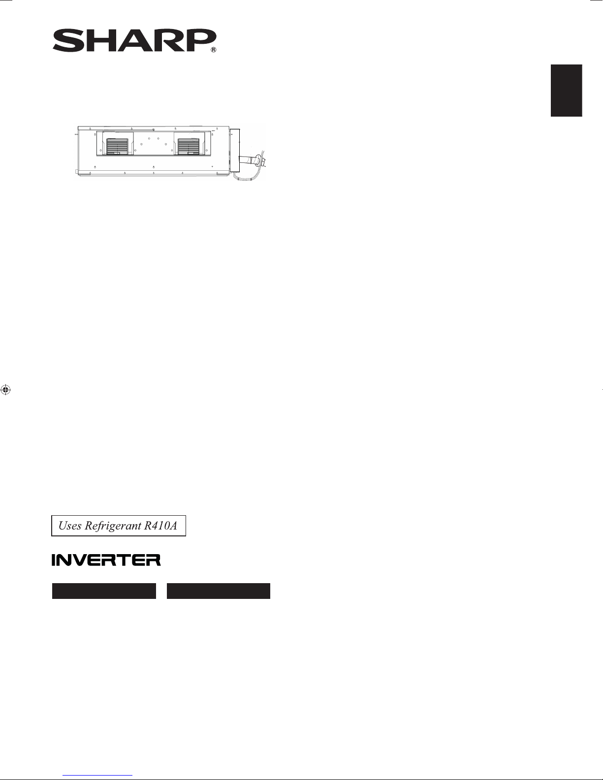
DUCT TYPE ROOM AIR CONDITIONER
INSTALLATION AND OPERATION MANUAL
ENGLISH
ITALIANO
INDOOR UNIT OUTDOOR UNIT
GB-X18SCR GU-X18SCR
GB-X24SCR GU-X24SCR
GB-X36SCR GU-X36SCR
Page 2

Page 3

Information on the Disposal of this Equipment
IF YOU WISH TO DISPOSE OF THIS EQUIPMENT, DO NOT USE THE ORDINARY
WASTE BIN, AND DO NOT PUT THEM INTO A FIREPLACE!
Used electrical and electronic equipment should always be collected and treated
SEPARATELY in accordance with local law.
Separate collection promotes an environment-friendly treatment, recycling of materials,
and minimizing final disposal of waste. IMPROPER DISPOSAL can be harmful to
human health and the environment due to certain substances! Take USED EQUIPMENT
to a local, usually municipal, collection facility, where available.
If in doubt about disposal, contact your local authorities or dealer and ask for the
correct method of disposal.
Page 4

1 Safety Precautions .......................................................................................... 1
2 Outline of the Unit and Main Parts................................................................... 2
3 Preparative for Installation ............................................................................... 3
3.1 Standard Accessory Parts .......................................................................... 3
3.2 Selection of the Installation Location .......................................................... 4
3.3 Connection Pipe Requirement ................................................................... 5
3.4 Electrical Requirement ............................................................................... 6
4 Installation of the Unit ...................................................................................... 7
4.1 Installation of the Indoor Unit ...................................................................... 7
4.2 Installation of the Outdoor Unit ................................................................. 11
4.3 Installation of the Connection Pipe ........................................................... 12
4.4 Vacuum and Gas Leakage Inspection ...................................................... 16
4.5 Installation of the Drain Hose ................................................................... 17
4.6 Installation of the Duct .............................................................................. 20
4.7 Electrical Wiring ........................................................................................ 23
5 Installation of Controllers ............................................................................... 28
6 Test Running .................................................................................................. 28
6.1 Trial Operation and Testing ....................................................................... 28
6.2.Working Temperature Range .................................................................... 29
7 Unit Function ................................................................................................. 30
7.1 Setting of Double Indoor Room Sensors .................................................. 30
7.2 Checking of Outdoor Ambient Temperature ............................................. 30
7.3 Fresh Air Control ...................................................................................... 31
8 Troubleshooting and Maintenance ................................................................ 32
8.1 Troubleshooting ........................................................................................ 32
8.2 Routine Maintenance ............................................................................... 32
Contents
Page 5
DC Inverter Duct Type Unit
1
1 Safety Precautions
WARNING!
This mark indicates procedures which, if improperly performed, might lead to the
death or serious injury of the user.
CAUTION!
This mark indicates procedures which, if improperly performed, might possibly
result in personal harm to the user, or damage to property.
WARNING!
(1). For operating the air conditioner pleasantly, install it as outlined in this installation manual.
(2). Connect the indoor unit and outdoor unit with the room air conditioner piping and cord available
from our standard parts. This installation manual describes the correct connections using the
installation set available from our standard parts.
(3). Installation work must be performed in accordance with national wiring standards by authorized
personnel only.
(4). If refrigerant leaks while work is being carried out, ventilate the area. If the refrigerant comes in
contact with a ame, it produces toxic gas.
(5). Do not power on until all installation work is complete.
(6). During installation, make sure that the refrigerant pipe is attached firmly before you run the
compressor.
Do not operate the compressor under the condition of refrigerant piping not attached properly with
2-way or 3-way valve open.
This may cause abnormal pressure in the refrigeration cycle that leads to breakage and even
injury.
(7). During the pump-down operation, make sure that the compressor is turned off before you remove
the refrigerant piping.
Do not remove the connection pipe while the compressor is in operation with 2-way or 3-way
valve open.
This may cause abnormal pressure in the refrigerant cycle that leads to breakage and even injury.
(8). When installing and relocating the air conditioner, do not mix gases other than the specified
refrigerant (R410A) to enter the refrigerant cycle.
If air or other gas enters the refrigerant cycle, the pressure inside the cycle will rise to an
abnormally high value and cause breakage, injury, etc.
(9). This appliance can be use by children aged fron
8 years and above and persons with reduced
physical, sensory or mental capab
ilities or lack of experience and kowledge if they have been
given supervision or instruction
concerning use of the appliance in a safe way and understand
the hazards involved.
(10).
Children shall not play with the appliance. Cleaning and user maintenance shall not be made by
children without supervision.
(11). If the supply cord is damaged, it must be replaced by the manufacturer, its service agent or
similarly qualied persons in order to avoid a hazard.
Page 6
DC Inverter Duct Type Unit
2
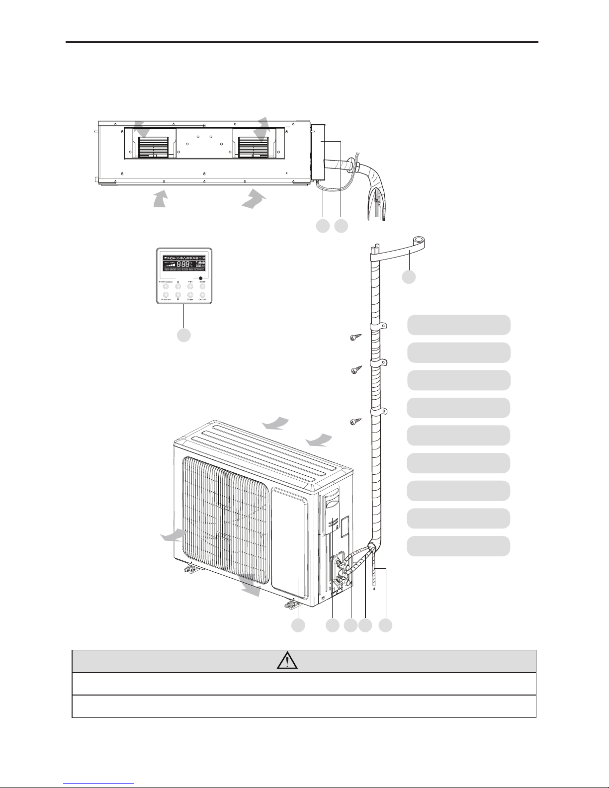
2 Outline of the Unit and Main Parts
Indoor
Outdoor
1. Power Cord
2. Electric Box
3. Wired Controller
4. Binding tape
5. Drain Pipe
6. Gas Pipe
7. Liquid Pipe
8. Big Handle
9. Front Board
1 2
3
4
9
Air outlet
Air outlet
Air inlet
Air inlet
Fig.1
NOTE!
① .
The connection pipe and duct for this unit should be prepared by the user.
② .
The unit is standard equipped with rectangular duct.
8 7 6
5
Page 7
DC Inverter Duct Type Unit
3
3 Preparative for Installation
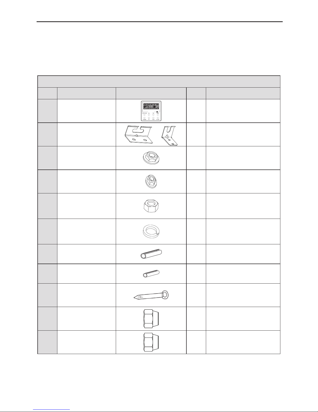
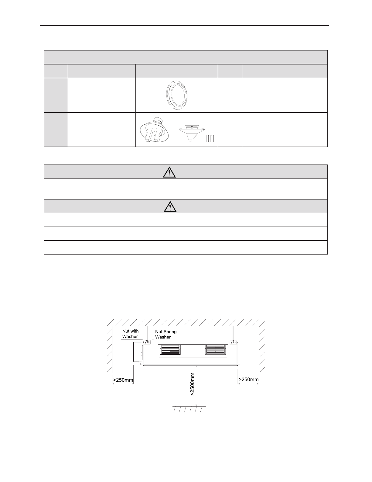
3.1 Standard Accessory Parts
The standard accessory parts listed below are furnished and should be used as required.
Table 1
Indoor Unit Accessories
No. Name Appearance Q'ty Usage
1 Wired Controller 1 To control the indoor unit
2 Hanger or 4 To x the indoor unit
3 Nut with Washer 8
To x the hook on the cabinet
of the unit.
4 Nut with Washer 4
To x the hook on the cabinet
of the unit.
5 Nut 4
To be used together with the
hanger bolt for installing the
unit.
6 Washer 4
To be used together with the
hanger bolt for installing the
unit.
7 Insulation 1 To insulate the gas pipe
8 Insulation 1 To insulate the liquid pipe
9 Fastener 8 To fasten the sponge
10 Nut 1 To connect liquid pipe
11 Nut 1 To connect gas pipe
Page 8
DC Inverter Duct Type Unit
4
Table 2
Outdoor Unit Accessories
No. Name Appearance Q'ty Usage
1 Drain Plug 3 To plug the unused drain hole.
2 Drainage Connecter
or
1
To connect with the hard PVC
drain pipe
3.2 Selection of the Installation Location
WARNING!
The unit must be installed where strong enough to withstand the weight of the unit and xed securely,
otherwise the unit would topple or fall off.
CAUTION!
① .
Do not install where there is a danger of combustible gas leakage.
② .
Do not install the unit near heat source, steam, or ammable gas.
③ .
Children under 10 years old must be supervised not to operate the unit.
Decide the installation location with the customer as follows:
3.2.1 Indoor Unit
(1). Install the unit at a place where is strong enough to withstand the weight of the unit.
(2). The air inlet and outlet of the unit should never be clogged so that the airow can reach
every corner of the room.
(3). Leave service space around the unit as required in Fig.2.
Fig.2
(4). Install the unit where the drain pipe can be easily installed.
(5). The space from the unit to the ceiling should be kept as much as possible so as for more
convenient service.
Page 9
DC Inverter Duct Type Unit
5
3.2.2 Outdoor Unit
WARNING!
① .
Install the unit where it will not be tilted by more than 5°.
② .
During installation, if the outdoor unit has to be exposed to strong wind, it must be fixed
securely.
(1). If possible, do not install the unit where it will be exposed to direct sunlight. (If necessary,
install a blind that does not interfere with the air ow.)
(2). Install the outdoor unit in a place where it will be free from getting dirty or getting wet by
rain as much as possible.
(3). Install the outdoor unit where it is convenient to connect the indoor unit.
(4). Install the outdoor unit where the condensate water can be drained out freely during
heating operation. Do not place animals and plants in the path of the warm air.
(5). Take the air conditioner weight into account and select a place where noise and vibration
are small.
(6). Install the outdoor unit where is capable of withstanding the weight of the unit and
generates as less noise and vibration as possible.
(7). Provide the space shown in Fig.3, so that the air flow is not blocked. Also for efficient
operation, leave three of four directions of peripheral constructions open.
Units: mm
>500
>500 >500
>500
>2000
>2000
>1000
Fig.3
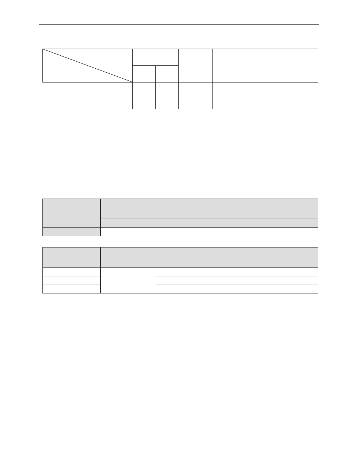
3.3 Connection Pipe Requirement
CAUTION
!
The maximum length of the connection pipe is listed in the table below. Do not place the units between
which the distance exceeds the maximum length of the connection pipe.
Page 10
DC Inverter Duct Type Unit
6
Table 3
Size of Fitting
Pipe(Inch)
Max.
Pipe
Length
(m)
Max. Height
Difference between
Indoor Unit and
Outdoor Unit (m)
Drainage
pipe(Outer
Diameter × wall
thickness) (mm)
Liquid Gas
GB-X18SCR GU-X18SCR 1/4 1/2 20 15 Φ30X1.5
GB-X24SCR GU-X24SCR 3/8 5/8 30 15 Φ20X1.2
GB-X36SCR GU-X36SCR 3/8 5/8 30 15 Φ20X1.2
① .
The connection pipe should be insulated with proper water-proof insulating material.
② .
The pipe wall thickness shall be 0.5-1.0mm and the pipe wall shall be able to withstand the
pressure of 6.0 MPa.The longer the connecting pipe, the lower the cooling and heating effect
performs.
3.4 Electrical Requirement
Electric Wire Size and Fuse Capacity.
Table 4
Indoor Units
Power Supply
Fuse Capacity Breaker Capacity
Min. Power Supply
Cord
V/Ph/Hz A A mm
2
18K~36K 220-240V~ 50Hz 5 6 1.0
Table 5
Model
Power
Supply
Capability of Air
Switch(A)
Minimum Sectional Area of Power Cable
and Earth line (mm2)
220-240V
~
50Hz
GU-X18SCR 16 1.5
GU-X24SCR 20 2.5
GU-X36SCR 25 2.5
Item
Model
Page 11
DC Inverter Duct Type Unit
7
Note:
① .
The fuse is located on the main board.
② .
Install the disconnect device with a contact gap of at least 3mm in all poles nearby the units
(Both indoor unit and outdoor unit).The appliance must be positioned so that the plug is
accessible.
③ .
The specications of the breaker and power cable listed in the table above are determined
based on the maximum power (maximum amps) of the unit.
④ .
The specifications of the power cable listed in the table above are applied to the conduit-
guarded multi-wire copper cable (like, YJV copper cable, consisting of PE insulated wires and
a PVC cable jacket) used at 40°С and resistible to 90°С(see IEC 60364-5-52). If the working
condition changes, they should be modied according to the related national standard.
⑤ .
The specifications of the breaker listed in the table above are applied to the breaker with
the working temperature at 40°С. If the working condition changes, they should be modied
according to the related national standard.
⑥ .
Take 2 pieces of power cord of 0.75mm2 as the communication lines between indoor and
outdoor unit, with their longest lengths of 50m. Please select the appropriate line length as per
the actual installation conditions. The communication lines can not be twisted together. For
the unit (≤30K), it’s recommended to use 8m long communication line.
⑦ .
Take 2 pieces of power cord of 0.75mm2 as the communication lines between the wired
controller and the indoor unit, with their longest lengths of 30m. Please select the appropriate
line length as per the actual installation conditions. The communication lines can not be twisted
together. It’s recommended to use 8m long communication line.
⑧ .
The wire size of the communication line should be no less than 0.75mm2. It’s recommended to
take 0.75mm2 power cords as the communication line.
4 Installation of the Unit
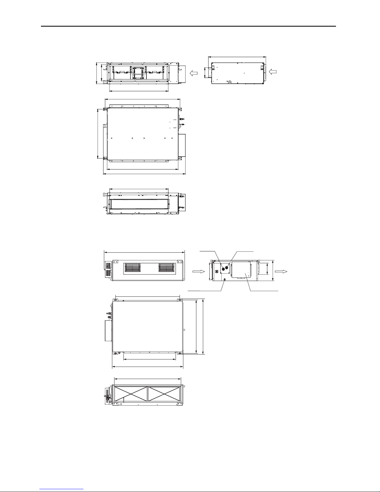
4.1 Installation of the Indoor Unit
4.1.1 Indoor unit dimension
WARNING!
① .
Install the indoor unit in a location which can withstand a load of at least ve times the weight
of the main unit and which will not amplify sound or vibration.
② .
If the installation location is not strong enough, the indoor unit may fall and cause injuries.
③ .
If the job is done with the panel frame only, there is a risk that the unit will come loose. Please
take care.
Page 12
DC Inverter Duct Type Unit
8
For the units: 18K
J
B
H
I
G
F
Max
Air intake
E
D
C
Max
A
For the units: 24~36K
J
I
H
G
B
F
A
E
C
D
Gas Pipe
Liquid Pipe
Drainage Pipe
Electric Box
Air Intake
Max
Max
Page 13

DC Inverter Duct Type Unit
9
Table 6
Item
Model
A B C D E F G H I J
945 618 738 892 1037 721 738 125 203 266 GB-X18SCR
GB-X24SCR
1101 517 820 1159 1279 558 1002 160 235 268
1011 748 820 1115 1226 775 979 160 231 290
GB-X36SCR
Page 14

DC Inverter Duct Type Unit
10
4.1.2 Drilling Holes for Bolts and Installing the Bolts
Using the installation template, drill holes for bolts (four holes). (Fig. 5)
4.1.3 Installing the Suspension Bolts
(1). Install the bolts to the ceiling at a place strong enough to hang the unit. Mark the bolt
positions from the installation template. With a concrete drill, drill for 12.7mm (1/2”)
diameter holes. (Fig. 6)
(2). Insert the anchor bolts into the drilled holes, and drive the pins completely into the anchor
bolts with a hammer. (Fig. 7)
(3). Install the hanger to the unit. (Fig.8)
(4). Pass the unit hangers over the bolts installed to the ceiling and install the unit with the
special nut.(Fig.9)
60 to 70 mm
Fig.6Fig. 5 Fig.7
Φ12.7mm
Fig.8
Hanger
I
I
2:1
Hook
Screw
Nut
Nu
t
Fig.9
Page 15

DC Inverter Duct Type Unit
11
4.1.4 Leveling
The water level test must be done after installing the indoor unit to make the unit is horizontal,
as shown below.
Horizontal tester
4.2 Installation of the Outdoor Unit
WARNING
① .
Install the unit where it will not be tilted by more than 5°.
② .
During installation, if the outdoor unit has to be exposed to strong wind, it must be fixed
securely.
4.2.1 Outdoor unit dimension
D
A
B
C
E
Fig.11
Fig.10
Page 16

DC Inverter Duct Type Unit
12
GU-X24SCR 980 427 790 610 395
GU-X36SCR
1107 440 1100 631 400
4.2.2 Condensate Drainage of the Outdoor Unit(Only for the heat pump unit) (Fig.12)
(1). It is required to install a drain pipe for the outdoor unit to drain out the condensate water
during heating operation. (only for the heat pump unit)
(2). When installing the drain pipe, apart from the drain pipe mounting hole, all other holes
should be plugged so as to avoid water leakage.(only for the heat pump unit)
(3). Installation Method: Insert the pipe joint into the hole φ25 located at the base plate of the
unit and then connect the drain pipe to the pipe joint.
Bottom
Drain cap
Drain pipe mounting hole
Fig.12
4.3 Installation of the Connection Pipe
4.3.1 Flare Processing
(1). Cut the connection pipe with the pipe cutter and remove the burrs.
(2). Hold the pipe downward to prevent cuttings from entering the pipe.
(3). Remove the are nuts at the stop valve of the outdoor unit and inside the accessory bag of
the indoor unit, then insert them to the connection pipe, after that, are the connection pipe
with a aring tool.
(4). Check if the are part is spread evenly and there are no cracks (see Fig.13).
Fig.13
Table 6 Unit: mm
Item
Model
A B C D E
GU-X18SCR 955 396 700 560 360
Page 17

DC Inverter Duct Type Unit
13
4.3.2 Bending Pipes
(1). The pipes are shaped by your hands. Be careful not to collapse them.
×
√
Fig.14
(2). Do not bend the pipes in an angle more than 90°.
(3). When pipes are repeatedly bent or stretched, the material will harden, making it difcult to
bend or stretch them any more. Do not bend or stretch the pipes more than three times.
(4). When bending the pipe, do not bend it as is. The pipe will
be collapsed. In this case, cut the heat insulating pipe
with a sharp cutter as shown in Fig.15, and bend it after
exposing the pipe. After bending the pipe as you want, be
sure to put the heat insulating pipe back on the pipe, and
secure it with tape.
Fig.15
Pipe
Cutter
Cutt line
Heat insulating
pipe
CAUTION!
① .
To prevent breaking of the pipe, avoid sharp bends. Bend the pipe with a radius of curvature
of 150 mm or over.
② .
If the pipe is bent repeatedly at the same place, it will break.
4.3.3 Connecting the Pipe at the Indoor Unit Side
Detach the caps and plugs from the pipes.
CAUTION!
① .
Be sure to apply the pipe against the port on the indoor unit correctly. If the centering is
improper, the flare nut cannot be tightened smoothly. If the flare nut is forced to turn, the
threads will be damaged.
② .
Do not remove the are nut until the connection pipe is to be connected so as to prevent dust
and impurities from coming into the pipe system.
Centering the pipe against port on the indoor unit, turn the are nut with your hand.
CAUTION!
Hold the torque wrench at its grip, keeping it in the right angle with the pipe as shown in Fig. 15,
in order to tighten the are nut correctly.
Page 18

DC Inverter Duct Type Unit
14
When the are nut is tightened properly by your hand, use a torque wrench to nally tighten it.
Fig.16
Fig.17
Table 7 Flare nut tightening torque
Pipe Diameter Tightening Torque
1/4˝(Inch) 15-30 (N·m)
3/8˝(Inch) 35-40 (N·m)
5/8˝(Inch) 60-65 (N·m)
1/2˝(Inch) 45-50 (N·m)
CAUTION!
Be sure to connect the gas pipe after connecting the liquid pipe completely.
4.3.4 Connecting the Pipe at the Outdoor Side Unit
Tighten the flare nut of the connection pipe at the outdoor unit
valve connector. The tightening method is the same as that as at
the indoor side.
4.3.5 Checking the Pipe Connections for Gas Leaking
For both indoor and outdoor unit side, check the joints for gas
leaking by the use of a gas leakage detector without fail when
the pipes are connected.
4.3.6 Heat Insulation on the Pipe Joints (Indoor Side Only)
Stick coupler heat insulation (large and small) to the place where connecting pipes.
Fig.18
Page 19

DC Inverter Duct Type Unit
15
Fig.19
4.3.7 Liquid Pipe and Drain Pipe
Sealed
Drain
pipe
Saddle
Fig.20
Fig.21
Trap
If the outdoor unit is installed lower than
the indoor unit (See Fig.20)
(1). A drain pipe should be above ground
and the end of the pipe does not
dip into water. All pipes must be
restrained to the wall by saddles.
(2). Taping pipes must be done from
bottom to top.
(3). All pipes are bound together by tape
and restrained to wall by saddles.
If the outdoor unit is installed higher than
the indoor unit (See Fig.21)
(1). Taping should be done from lower to
the upper part.
(2). All pipes are bound and taped
together and also should be trapped
to prevent water from returning to the
room (See Fig.49)
(3). Restraint all pipes to the wall with
saddles.
Page 20

DC Inverter Duct Type Unit
16
4.4 Vacuum and Gas Leakage Inspection
CAUTION!
Do not purge the air with refrigerants but use a vacuum pump to vacuum the installation! There is
no extra refrigerant in the outdoor unit for air purging!
4.4.1 Vacuum
(1). Remove the caps of the liquid valve, gas valve and also the service port.
(2). Connect the hose at the low pressure side of the manifold valve assembly to the service
port of the unit’s gas valve, and meanwhile the gas and liquid valves should be kept closed
in case of refrigerant leak.
(3). Connect the hose used for evacuation to the vacuum pump.
(4). Open the switch at the lower pressure side of the manifold valve assembly and start the
vacuum pump. Meanwhile, the switch at the high pressure side of the manifold valve
assembly should be kept closed, otherwise evacuation would fail.
(5). The evacuation duration depends on the unit’s capacity, generally,
20 minutes for the 18K units, 30 minutes for the 36K units,
And verify if the pressure gauge at the low pressure side
of the manifold valve assembly reads -1.0Mp (-75cmHg), if not, it indicates there is leak
somewhere. Then, close the switch fully and then stop the vacuum pump.
(6). Wait for some time to see if the system pressure can remain unchanged,
5 minutes for the 18K~24K units, 10 minutes for the unit 36k
During this time, the reading of the pressure gauge at the low pressure side can not
be larger than 0.005Mp (0.38cmHg).
(7). Slightly open the liquid valve and let some refrigerant go to the connection pipe to balance
the pressure inside and outside of the connection pipe, so that air will not come into the
connection pipe when removing the hose. Note that the gas and liquid valve can be opened
fully only after the manifold valve assembly is removed.
(8). Place back the caps of the liquid valve, gas valve and also the service port.
Hose with the valve pin
gauge manifold
pipe
pipe
VAC valve
Vacuum pump
Service port
Low pressure gauge
High pressure gauge
Gauge manifold kit
Fig.22
Note: For the large-sized unit, it has the service port for both the gas valve and the liquid valve.
Page 21

DC Inverter Duct Type Unit
17
During evacuation, it is available to connect two hoses of the manifold valve assembly to two
service ports to quicken the evacuating speed.
4.4.2 Additional Charge
Refrigerant suitable for a piping length of 5m is charged in the 18~36K outdoor unit at the
factory.
When the piping of 18~36k unit is longer than 7.5m,
additional charging is necessary .
For the additional amount, see Table 8.
Table 8
Model
Item
Standard Pipe Length
Unnecessary Charge
Pipe Length
Additional Refrigerant Amount
for Extra Pipe
18K 5m ≤ 7.5m 30 g/m
24~36K 5m ≤ 7.5m 60 g/m
When the height difference between the indoor unit and outdoor unit is larger than 10 meters,
an oil bend should be employed for every 6 meters.
Oil bend
Oil bend
Indoor
Outdoor
6m
4.5 Installation of the Drain Hose
4.5.1 Installation of Drain Piping
CAUTION!
Install the drain hose in accordance with the instructions in this installation manual and keep the
area warm enough to prevent condensation. Problems with the piping may lead to water leaks.
(1). Install the drain hose with downward gradient (1/50 to 1/100) and no risers or traps are
used for the hose.(Fig.23)
(2). Be sure there is no crack or leak on the drain hose to avoid the formation of air pocket.
(Fig.23)
(3). When the hose is long, install supporters.(Fig.24)
(4). Always use the drain hose which has been insulated properly.
Page 22

DC Inverter Duct Type Unit
18
×
√
Fig.23
Fig.24 Fig.25
As the inside of the unit
is in the negative pressure
status, it is required to set
up a backwater elbow. The
requirements is:
A=B≥P/10+20(mm)
P is the absolute pressure
inside the unit. The unit of the
pressure is Pa.
Condensate Drainpipe
B
A
Condensate Drainpipe
Enlarged View
B
A
Fig.26
Page 23

DC Inverter Duct Type Unit
19
(5). Use a suitable drain hose, and see Table 3 for its size.
(6). There is a drain port on both the left and right sides. Select
the drain port to match the local conditions.(Fig.25)
(7). When the unit is shipped from the factory, the drain port is
defaulted to be the one on the left side (electric box side),
the port on right side has been plugged.
(8). When using the drain port on the right side of the unit,
reinstall the drain cap to the left side drain port.(Fig.27)
Fig.27
CAUTION!
Always check that the drain cap is installed to the unused drain port and is fastened with the nylon
fastener. If the drain cap is not installed, or is not sufciently fastened by the nylon fastener, water may
drip during the cooling operation.
(9). Be sure to insulate where the drain port and the drain hose is connected.(Fig.28 )
(10). The unused drain port also should be insulated properly.(Fig.29)
Fig.28 Fig.29
(11). There is adhesive on one side of the insulation so that after removing the protective paper
over it the insulation can be directly attached to the drain hose.
(12). Considerations for the unit with the condensate pump:
i). For the unit with the condensate pump, only one drain port at the side close to the electric
box is prepared and only through it the drain hose can be connected.
ii). See table 3 for the size of the drain port of the unit with the condensate pump, which is
different from that of the unit without the condensate pump.
iii). For the unit with the condensate pump, two drain ports at the bottom are defaulted to be
factory plugged with drain caps. After the installation of the drain hose, these two drain
ports also need to be insulated properly with the same way aforementioned.
iv). The drain hose for the unit with the condensate pump should be arranged as shown in the
gure below.
Fig.30
a. The vertical height of the drain hose should be 75mm or less so that it is unnecessary for
1000mm
Page 24

DC Inverter Duct Type Unit
20
the drain port to withstand additional force.
Fig.31
b. When multiple drain hoses are used, their installation should be performed as shown in the
gure below.
0~1000mm
Fig.32
4.5.2 Testing of Drain Piping
After piping work is finished, check if drainage
ows smoothly.
As shown in the figure, add approximately
1liter of water slowly into the drain pan and check
drainage ow during COOL running.
4.6 Installation of the Duct
4.6.1 Dimensions of the Supply Air Outlet/Return Air Inlet
Fig.33
B
21
A
Fig.34 Supply Air Outlet
Page 25

DC Inverter Duct Type Unit
21
Fig.35 Return Air Inlet
Table 9
Item
Model
Supply Air Outlet Return Air Inlet
A B C D
GB-X18SCR 123 736 710 166
GB-X24SCR 158 818 994 195
GB-X36SCR 158 818 1000 206
4.6.2 Installation of the Supply Air Duct
(1). Installation of the Rectangular Duct.
No. Name No. Name
1 Hanger 5 Filter
2 Air Intake Pipe 6
Main Air
Supply Pipe
3
Canvas Air
Pipe
7
Air Supply
Outlet
4 Air Intake
Fig.36
CAUTION!
① .
The maximum length of the duct means the maximum length of the supply air duct plus the
maximum length of the return air duct.
② .
The duct is rectangular and connected with the air inlet/outlet of the indoor unit. Among all
supply air outlets, at least one should be kept open.
Bottom Return Air Installation only for Units 09/12/18K
Page 26

DC Inverter Duct Type Unit
22
(2). The default installation location of the rectangular ange is at the back, as shown in Fig.37.
Return Air Cover Plate
Bottom Return Air
Rear Return Air
Rectangular Flange
Fig.37
(3). If the bottom return air is desired, just change the place of the rectangular ange and the
return air cover plate.
(4). Connect one end of the return air duct to the return air outlet of the unit by rivets and the
other to the return air louver. For the sake of the convenience to freely adjust the height, a
cutting of canvas duct will be helpful, which can be reinforced and folded by 8# iron wire.
(5). More noise is likely to be produced in the bottom return air mode than the backward return
air mode, so it is suggested to install a silencer and a static pressure box to minimize the
noise.
(6). The installation method can be chosen with considering the conditions of the building and
maintenance etc., as shown in Fig.38.
1
Return air Return air
Install the Return Air Duct (a)
Supply air Supply air
Install the Return Air Duct (b)
1
2
4
5
3
64
5
Supply air
Supply air
Return air
Return air
Install the return air duct (b)Install the return air duct (a)
Fig.38 Install the return air duct
Table 10 Installation of the return air duct
No. Name No. Name
1 Return Air Inlet (with lter) 4 Indoor unit
2 Canvas Duct 5 Supply Air Duct
3 Return Air Duct 6 Grille
Page 27

DC Inverter Duct Type Unit
23
4.7 Electrical Wiring
4.7.1 Wiring Precautions
WARNING !
① .
Before obtaining access to terminals, all supply circuits must be disconnected.
② .
The rated voltage of the unit is as shown as table 4 and Table 5
③ .
Before turning on, verify that the voltage is within the 198~264V range(for single phrase unit)
④ .
Always use a special branch circuit and install a special receptacle to supply power to the air
conditioner.
⑤ .
Use a special branch circuit breaker and receptacle matched to the capacity of the air
conditioner.
⑥ .
The special branch circuit breaker is installed in the permanent wiring. Always use a circuit
that can trip all the poles of the wiring and has an isolation distance of at least 3mm between
the contacts of each pole.
⑦ .
Perform wiring work in accordance with standards so that the air conditioner can be operated
safely and positively.
⑧ .
Install a leakage special branch circuit breaker in accordance with the related laws and
regulations and electric company standards.
CAUTION !
① .
The power source capacity must be the sum of the air conditioner current and the current of
other electrical appliances. When the current contracted capacity is insufcient, change the
contracted capacity.
② .
When the voltage is low and the air conditioner is difcult to start, contact the power company
to raise the voltage.
4.7.2 Electrical Wiring
(1). For solid core wiring (Fig.39)
i). Cut the wire end with a wire cutter or wire-cutting pliers, then strip the insulation about 25
mm (15/16") .
ii). Using a screwdriver, remove the terminal screw(s) on the terminal board.
iii). Using pliers, bend the solid wire to form a loop suitable for the terminal screw.
iv). Shape the loop wire properly, place it on the terminal board and tighten securely with the
terminal screw using a screwdriver.
(2). For strand wiring (Fig.39)
i). Cut the wire end with a wire cutter or wire-cutting pliers, then strip the insulation about 10
mm (3/8") .
Page 28

DC Inverter Duct Type Unit
24
ii). Using a screwdriver, remove the terminal screw (s) on the terminal board.
iii). Using a round terminal fastener or pliers, securely clamp a round terminal to each stripped
wire end.
iv). Position the round terminal wire, and replace and tighten the terminal screw with a
screwdriver.(Fig.40)
Fig.39
Fig.40 Fig.41
(3). How to x connection cord and power cord by cord clamp
After passing the connection cord and power cord through the insulation tube, fasten it with the
cord clamp.(Fig.41)
WARNING!
① .
Before starting work, check that power is not being supplied to the indoor unit and outdoor
unit.
② .
Match the terminal block numbers and connection cord colors with those of the indoor unit
side.
③ .
Erroneous wiring may cause burning of the electric parts.
④ .
Connect the connection cords rmly to the terminal block. Imperfect installation may cause a
re.
⑤ .
Always fasten the outside covering of the connection cord with cord clamps. (If the insulator is
not clamped, electric leakage may occur.)
⑥ .
Always connect the ground wire.
Page 29

DC Inverter Duct Type Unit
25
(4). Electric wiring between the indoor and outdoor units
Single-phase units (18K~24K)
GU-X18SCR+GB-X18SCR
① .
Power cord 3×1.5mm
2
(H07RN-F)
② .
Power cord 3×1.0mm
2
(H05RN-F)
③ .
Communication Cords 2×0.75mm
2
(H05RN-F)
GU-X24SCR+GB-X24SCR
① .
Power cord 3×2.5mm
2
(H07RN-F)
② .
Power cord 3×1.0mm
2
(H05RN-F)
③ .
Communication Cords 2×0.75mm
2
(H05RN-F)
Single-phase units (36K)
GU-X36SCR+GB-X36SCR
① .
Power cord 3×2.5mm
2
(H07RN-F)
② .
Power cord 3×1.0mm
2
(H05RN-F)
③ .
Communication Cords 2×0.75mm
2
(H05RN-F)
Fig.42
Page 30

DC Inverter Duct Type Unit
26
(5). Electric wiring of indoor unit side
Remove the electric box cover from the electric box sub-assy and then connect the wire.
Fig.43
The F, C, O connect to the COMMOM, CLOSE and OPEN terminal of the fresh air valve
respectively.
CAUTION!
① .
The power cord and the wire of the fresh air valve are high-voltage, while the communication
cord and connection wire of the wired controller are low-voltage. They should run separately
against electromagnetic interference.
② .
The high-voltage and low-voltage lines should pass through the rubber rings at different
electric box covers.
③ .
Do not bundle the connection wire of the wired controller and the communication cord
together, or arrange them in parallel, otherwise improper operation would occur.
④ .
The high-voltage and low-voltage lines should be xed separately and securely, with internal
big clamps for the former and small clamps for the latter.
⑤ .
Tighten the indoor/outdoor connection cord and power cord respectively on the terminal
boards with screws. Faulty connection may cause a re.
⑥ .
If the indoor unit connection cord (to the outdoor unit) and power supply are wired incorrectly,
the air conditioner may be damaged.
⑦ .
Connect the indoor unit connection cord properly based on the corresponding marks as
shown in Fig.42.
⑧ .
Ground both the indoor and outdoor units by attaching a ground wire.
⑨ .
Unit shall be grounded in compliance with the applicable local and national codes.
(6). Electric wiring of outdoor unit side
Note: When connecting the power supply cord, make sure that the phase of the power
supply matches with the exact terminal board. If not, the compressor will rotate reversely and
run improperly.
Remove the big handle of the outdoor unit and insert the end of the communication cord and
the power cable into the terminal board.
Page 31

DC Inverter Duct Type Unit
27
Single phase:
18K~24K
36K
Fig.44
Power lines should go along the right side plate and
be fixed to the fixation hook with binding wires to keep
no contact with pipelines. Communication lines between
indoor and outdoor units also should go along the right side
plate and keep away from power lines.
Routing of
External
Power Lines
Fig.46
Fig.45
Page 32

DC Inverter Duct Type Unit
28
5 Installation of Controllers
Refer to the Installation Manual of the controller for more details.
6 Test Running
6.1 Trial Operation and Testing
(1). The meaning of error codes as shown below:
Table 11
Number Error code Error Remarks
1 E1 Compressor high pressure protection
2 E2 Indoor anti-freeze protection
3 E3
Compressor low pressure protection, refrigerant lack
protection and refrigerant colleting mode
4 E4 Compressor high discharge temperature protection
5 E6 Communication error
6 E8 Indoor fan motor error
7 E9 Full water protection
8 F0 Indoor ambient temperature sensor error
9 F1 Evaporator temperature sensor error
10 F2 Condenser temperature sensor error
11 F3 Outdoor ambient temperature sensor error
12 F4 Discharge temperature sensor error
13 F5 Temperature sensor error of wired controller
15 C5 Capacity code error
16 EE Outdoor memory chip error
17 PF Electric box sensor error
18 H3 Compressor overload protection
19 H4 Overloading
20 H5 IPM protection
21 H6 DC fan motor error
22 H7 Drive desynchronizing protection
23 Hc Pfc protection
25 Lc Activation failure
26 Ld Compressor phase sequence protection
27 LE Compressor stalling protection
28 LF Power protection
29 Lp Indoor and outdoor mismatch
30 U7 4-way valve direction changing protection
31 P0 Drive reset protection
32 P5 Over-current protection
33 P6 Communication error between main control and drive
34 P7 Drive module sensor error
35 P8 Drive module over temperature protection
36 P9 Zero passage protection
37 PA AC current protection
Page 33

DC Inverter Duct Type Unit
29
38 Pc Drive current error
39 Pd Sensor connecting protection
40 PE Temperature drift protection
41 PL Bus low voltage protection
42 PH Bus high voltage protection
43 PU Charge loop error
44 PP Input voltage abnormality
45 ee Drive memory chip error
Note: When the unit is connected with the wired controller, the error code will be simultaneously
shown on it.
(2). Instructions to the Error Indicating Lamps on the Panel of the Duct Type Unit.
Power/Running
Indicating lamp
Cooling indicating lamp
Heating indicating lamp
Dehumidification
indicating lamp
“88” display
Receiver
“Cool” button
“Heat” button
Fig.47
6.2.Working Temperature Range
Table 12
Test Condition
Indoor Side Outdoor Side
DB(°C) WB(°C) DB(°C) WB(°C)
Nominal Cooling 27 19 35 24
Nominal Heating 20
−
7 6
Rated Cooling 32 23 48
−
Low Temp. Cooling 21 15 -15
−
Rated Heating 27
−
24 18
Low Temp. Heating 20
−
-10 -11
Note:
① .
② .
The air volume is measured at the relevant standard external static pressure.
③
Cooling (heating) capacity stated above is measured under nominal working conditions
corresponding to standard external static pressure. The parameters are subject to change
with the improvement of products, in which case the values on nameplate shall prevail.
.
In this table, there are two outside DB values under the low temp cooling conditions, and the
one in the brackets is for the unit which can operate at extreme low temperature.
Page 34

DC Inverter Duct Type Unit
30
7 Unit Function
7.1 Setting of Double Indoor Room Sensors
This series of ducted air-conditioning unit has two indoor room sensors. One is located at the
air intake of the indoor unit and the other one is located inside the wire controller.
User can select one from the two indoor room sensors on the basis of the engineering
requirement.
(Refer to the section of wire controller instructions for detailed operation.)
Indoor room sensor A
Indoor room sensor B
Fig.48
7.2 Checking of Outdoor Ambient Temperature
The outdoor ambient temperature can be checked on the wire controller for the convenience of
users before going out. (Refer to the section of wire controller instructions for detailed operation.)
Outdoor unit
Indoor unit
Outdoor room sensor
Fig.49
Page 35

DC Inverter Duct Type Unit
31
7.3 Fresh Air Control
11-levels control can be realized for the amount of fresh air taken in. The function not only
facilitates the health of users, but also controls the electricity consumption loss because of taking in
fresh air. This kind of control can be carried out through the wire controller. The function can set at
any time, goes into effect at any time, and features very simple operation. (Refer to the section of
wire controller instructions for detailed operation.)
Outdoor
fresh air
Fresh air
Air intake pipe
Air supply pipe
Indoor side
Air valve
Before starting up
the unit,please remove
all the sealing lm on the
healthy lter block
Fig.50
Page 36

DC Inverter Duct Type Unit
32
8 Troubleshooting and Maintenance
8.1 Troubleshooting
If your air-conditioning unit suffers from abnormal operation or failure, please rst check the
following points before repair:
Failure Possible Reasons
The unit cannot be started.
① .
The power supply is not connected.
② .
Electrical leakage of air-conditioning unit causes tripping of the leakage
switch.
③ .
The operating keys are locked.
④ .
The control loop has failure.
The unit operates for a
while and then stops.
① .
There is obstacle in front of the condenser.
② .
The control loop is abnormal.
③ .
Cooling operation is selected when the outdoor ambient temperature is
above 48°C.
Poor cooling effect.
① .
The air lter is dirty or blocked.
② .
There is heat source or too many people inside the room.
③ .
The door or window is open.
④ .
There is obstacle at the air intake or outlet.
⑤ .
The set temperature is too high.
⑥ .
There is refrigerant leakage.
⑦ .
The performance of room temperature sensor becomes worse
Poor heating effect
① .
The air lter is dirty or blocked.
② .
The door or window is not rmly closed.
③ .
The set room temperature is too low .
④ .
There is refrigerant leakage.
⑤ .
The outdoor ambient temperature is lower than -5°C.
⑥ .
Control loop is abnormal.
After carrying out the check of the above items and taking relevant measures to solve the
problems found but the air-conditioning unit still does not function well, please stop the operation
of the unit immediately and contact the local service agency designated by SHARP. Only
ask professional serviceman to check and repair the unit.
8.2 Routine Maintenance
Only a qualied service person is allowed to perform maintenance.
Before accessing to terminal devices, all power supply circuits must be disconnected.
Do not use water or air of 50°C or higher for cleaning air lters and outside panels.
Note:
① .
Do not operate the air conditioner with the lter uninstalled, otherwise dust would come into
the unit.
② .
Do not remove the air lter except for cleaning. Unnecessary handling may damage the lter.
③ .
Do not clean the unit with gasolene, benzene, thinner, polishing powder or liquid insecticide,
Page 37

DC Inverter Duct Type Unit
33
otherwise it would cause discoloration and deformation of the unit.
④ .
Do not wet the indoor unit in case of electric shock or re hazard.
Increase the frequency of cleaning if the unit is installed in a room where the air is extremely
contaminated.(As a yardstick for yourself, consider cleaning the lter once a half year.)
If dirt becomes impossible to clean, change the air lter. (Air lter for exchange is optional.)
i). Removing the air lter from the duct.
ii). Cleaning the air lter
Remove dust from the air lter using a vacuum cleaner and gently rinse them in cool water. Do
not use detergent or hot water to avoid lter shrinking or deformation. After cleaning dry them
in the shade.
Press the return air inlet lter
downward against the guide groove
sponge and take it off along the arrow
direction.There are two return air inlet
lters.
iii). Replacing the air lter
Reinstall the lter as before.
Page 38

Page 39

 Loading...