

Page 1
Page 2
Page 3
Page 4
Page 5
Page 6
Page 7
Page 8
Page 9
Page 10

Page 11

Page 12

Page 13

Page 14

Page 15

Page 16

Page 17

Page 18

Page 19

Page 20

DV5131-003
Month of Issue: October 1994
Classification: Routine
TELEVISION TECHNICAL BULLETIN
Subject: Alternative chopper transformer fitting instructions
MODELS DV5131 DV5150
SYMPTOM
ACTION
During production, the manufacturer of the chopper transformer, T701, was changed.
If chopper transformer, T701, RTRNZ0510BMZZ (current type manufactured by Eldor)
ha been fitted then ensure that R746 is 2.29.
If chopper transformer, T701, RTRNZ0511BMZZ (alternative type manufactured by
Diemen) has been fitted then ensure that R746 is 3.39.
Use the part numbers given below.
Note that R746 is a safety resistor and the part number below must be used when
replacing this item.
Page 1 of 1
REF NO
DESCRIPTION PART NUMBER PRICE CODE
T701 Chopper TX (alternative) RTRNZ0511BMZZ AV
T701 Chopper TX (current) RTRNZ0510BMZZ AV
R746
R746
3.39, ½W (alternative)
2.29, ½W (current)
RR-XZ0206BMZZ AB
RR-XZ0204BMZZ AB
Sharp Electronics (UK) Limited
Reference UK40300X
Revision
White Carry out as required
Yellow Carry out as required and whenever the unit comes in for service
Red Carry out on all units
1
Page 21

CTV951203
Month of Issue:
Classification: Immediate
TELEVISION TECHNICAL BULLETIN
Page 1 of 1
MODELS DV5150H DV5103H
SYMPTOM
CAUSE
ACTION
When the mains voltage drops below 200VAC the picture starts to flicker.
R749
During production the value of R749 has been decreased from 39R to 22R.
REF NO DESCRIPTION PART NUMBER PRICE CODE
R749 22R 5% 0.5W Safety RR-XZ0219BMZZ AB
Originator AvW Supervisor Approval Date / / Reference AVW5150
White – Carry out as required, Yellow – Carry out as required and whenever the unit comes in for service, Red – Carry out on all units
Sharp Electronics (UK) Limited
Revision
Page 22

Date : 21 December 1998
Model: DV5131H
Ref No: DV5131-002
Classification: Immediate
TELEVISION TECHNICAL BULLETIN
Subject : Protection of frame output IC
SYMPTOM
CAUSE
ACTION
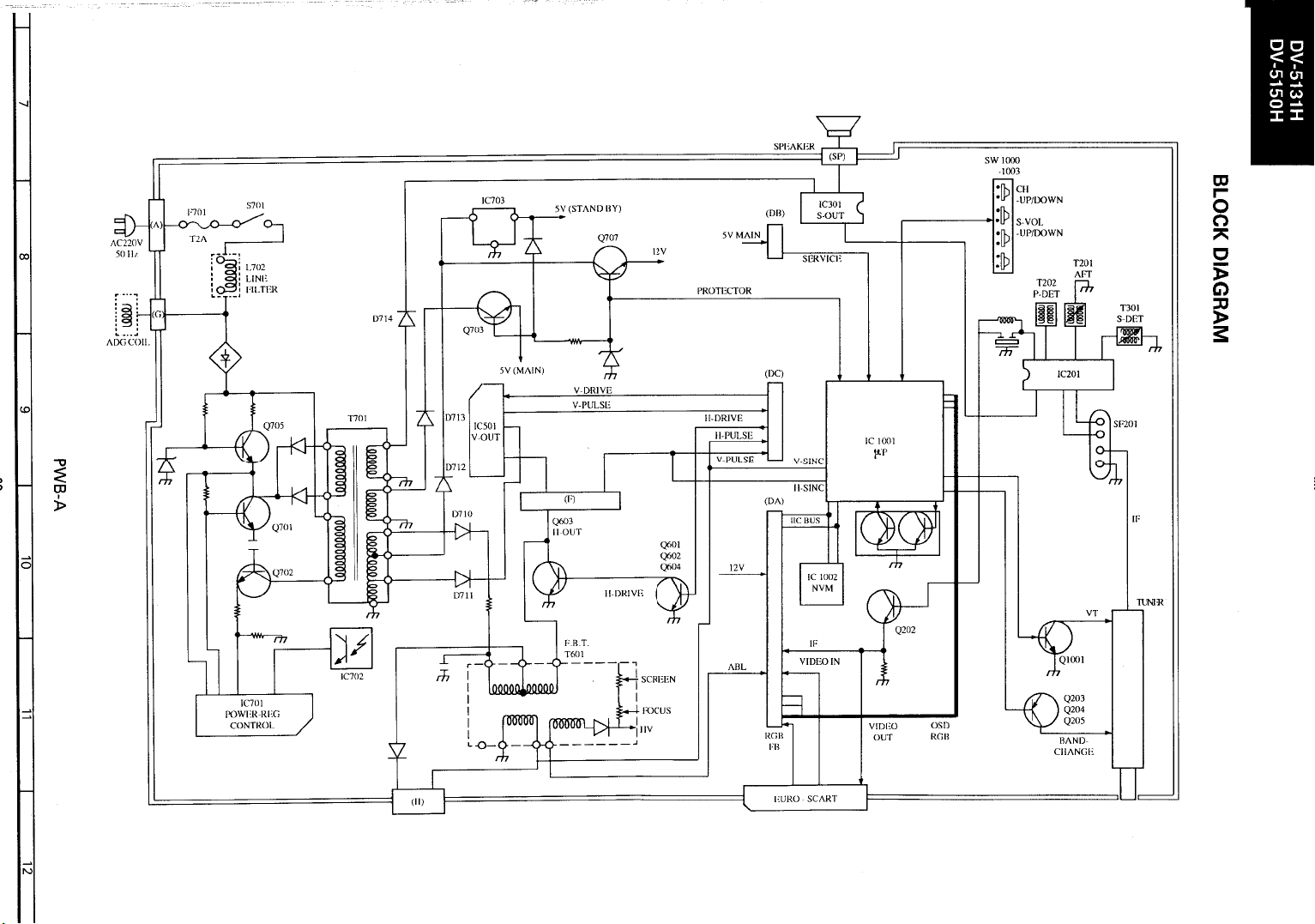
Failure of IC501
Increased flyback voltage.
When replacin g IC501, carry out the following circuit improvement using the part numbers
given belo w .
Page 1 of 1
1. Remo ve jumper from D502 position and insert a 4.7V zener diode in its place.
Polarisation is as indicated on the screen printing.
2 Fit diode D503 as indicated on PWB.
REF NO DESCRIPTION PART NUMBER PRICE CODE
D502 4.7V zener diode RH- E X0478BMZZ AB
D503 1N4004 diode RH-DX0501BMZZ AB
Originator ________ Supervisor_________ Approval Date ___/___/___ UK42500X
Sharp Electronics (UK) Ltd Technical Support Group
Page 23

DV3750-002
Month of Issue:
Classification: Immediate
TELEVISION TECHNICAL BULLETIN
MODELS DV3750H DV5131H DV5150H
SYMPTOM
CAUSE
ACTION
No operation.
The NVM is corrupted by electrostatic discharge.
Carry out the following circuit change.
1. Replace D710 with the new type diode.
2. Add a 10nF, 50V ceramic capacitor between pin 10 of IC1001 and ground (pin 11
of IC1001/Link 176).
3. Add a 10nF, 50V ceramic capacitor between pin 39 of IC1001 and ground (link 26).
Page 1 of 1
REF NO DESCRIPTION PART NUMBER PRICE CODE
D710 Diode, 1N4937 RH-DX0507BMZZ AB
- Capacitor 1nF, 50V VCKZPA1HF103Z AA
Originator AMu Supervisor Approval Date / / Reference UK44500X
White – Carry out as required, Yellow – Carry out as required and whenever the unit comes in for service, Red – Carry out on all units
Sharp Electronics (UK) Limited
Revision
Page 24

DV5131-009
Month of Issue:
Classification: Routine
TELEVISION TECHNICAL BULLETIN
Page 1 of 1
MODELS DV5150H DV5131H
SYMPTOM
CAUSE
ACTION
No chroma imediatly after channel change.
The chroma is slow to lock after channel change.
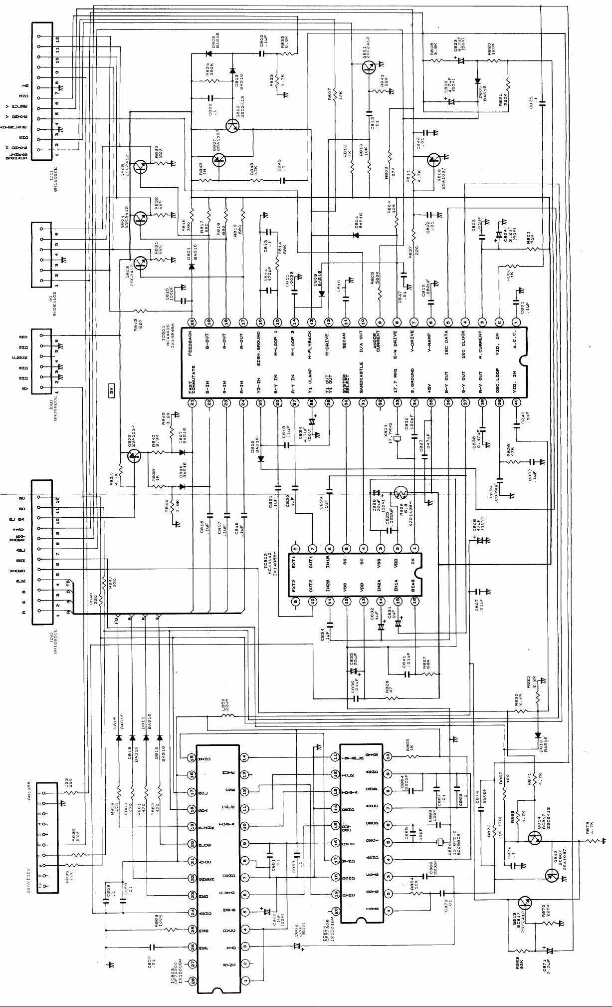
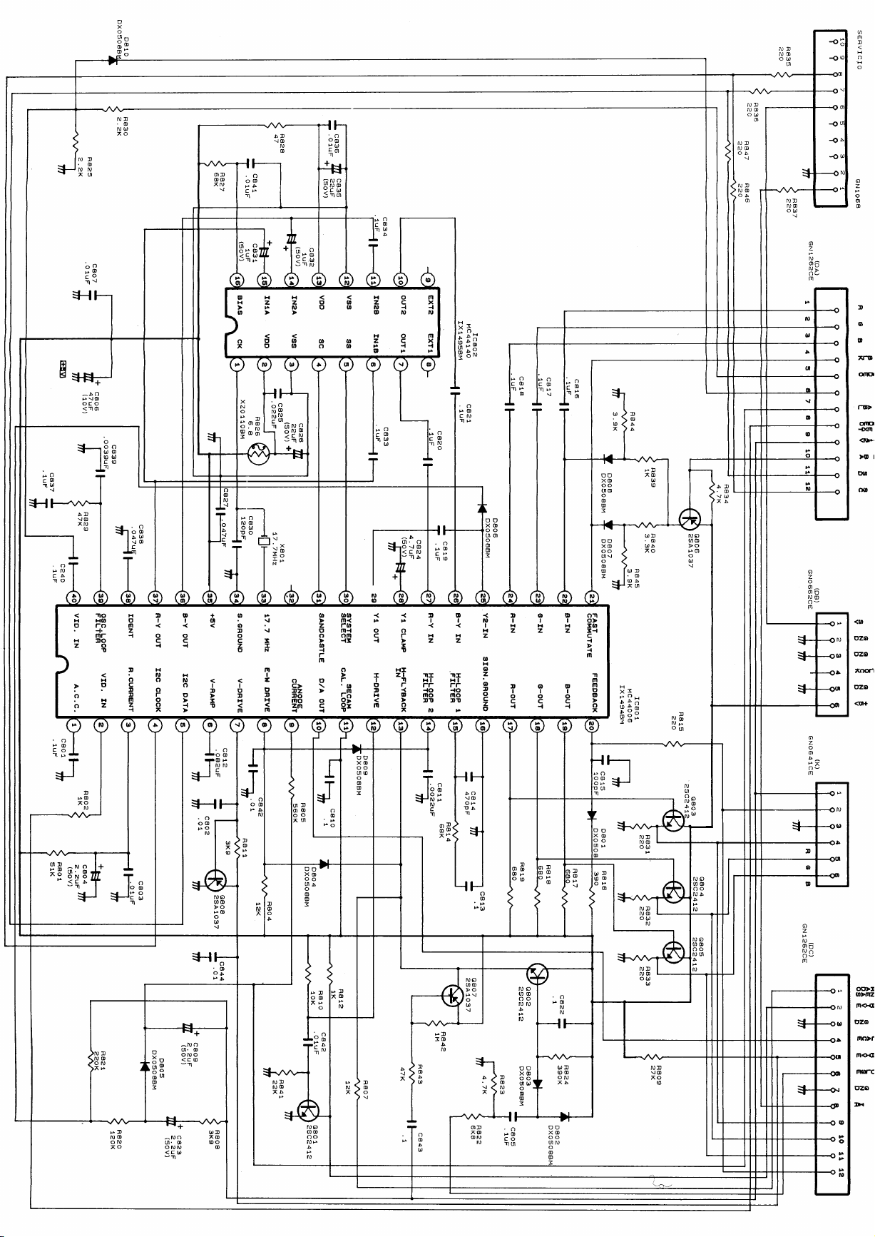
Add a 8.2M resistor between pins 35 and 39 of IC801.
REF NO DESCRIPTION PART NUMBER PRICE CODE
- Resistor 8.2M, 1/8W VRD-RA2BE825J AA
Originator AMu Supervisor Approval Date / / Reference SPN/492/QC
White – Carry out as required, Yellow – Carry out as required and whenever the unit comes in for service, Red – Carry out on all units
Sharp Electronics (UK) Limited
Revision
Page 25

CTV990502
g
Month of Issue: May 1999
Classification: White
TELEVISION TECHNICAL BULLETIN
Page 1 of 1
MODELS DV3750H DV3751H DV5150H DV5131H
Common faults on the S3B Chassis
Fault Reason Possible Cause
Black lines at bottom of picture Vertical stage tollerance Change C510 for a 4.7nF
Location of R507 Changes in production May be on bottom of PWB (ne
to ground
No teletext Data corruption Change NVM location 21 to 5A
No teletext/erratic problems Data corruption Refer to Technical Bulletin CTV960904
ative end of C506
Poor teletext response Poor filter response Remove C874 and fit a 100pF capacitor across
R871
Chroma slow to lock Poor lock in range Fit a 8.2M resistor from pin 35 (+5V) to pin 39
(osc loop) of IC801
No tuning Supply problems R1035/Q1001
Part number for AC retaining clip - LHLDK1501BM00
If you have a fault to add to the above l ist, please do no hesit ate to contact Sharp Technical Suppor t via the Hot Line
telephone number.
Sharp Electronics (UK) Limited
Reference
White – Carry out as required, Yellow – Carry out as required and whenever the unit comes in for service, Red – Carry out on all units
AVW280499/2
Revision 1
Page 26

CTV2000 07 21
Month of Issue: July 2000
Classification: White
TELEVISION TECHNICAL BULLETIN
Page 1 of 1
MODELS DV3750H DV3751H DV5131H DV5150H
SYMPTOM
CAUSE
No AFC, poor tuning function.
R214 damaged due to the rear cover being put on incorrectly or the receiver being
dropped.
ACTION
Replace R214 using the part number below.
REF NO DESCRIPTION PART NUMBER PRICE CODE
R214 220k Resistor
Note:
Component to be source from your local supplier
Sharp Electronics (UK) Limited
Reference TT14072000-9
Revision
White Carry out as required
Yellow Carry out as required and whenever the unit comes in for service
Red Carry out on all units
1
Page 27

CTV960406
Issue : 01/03/96
Classification : Routine
TELEVISION TECHNICAL BULLETIN
MODELS DV5150H
SYMPTOM
CAUSE
ACTION
REF NO DESCRIPTION PART NUMBER PRICE CODE
When the television is used with either a weak signal source or a VCR, the
colour may become intermitttent.
IC801 unable to reso lve weak burst signal.
1. Fit a 470nF capacitor between pin 38 and ground of IC801.
2. Change R814 to 120k.
Page 1 of 1
Originator
Sharp Electronics (UK) Ltd Technical Support Group
$Y:
$Y:
Supervisor
3*-
Approval Date 01/ 03/96 SPN/ 920/QC
3*-
Page 28

CTV970502
Month of Issue : May 1997
Classification : White
TELEVISION TECHNICAL BULLETIN
MODELS DV5131H DV5150H
REASON
ACTION
During production of the above models, the manufacturer of the chopper
transformer ( T701 ) has been changed.
This change has taken place from the following serial numbers.
DV5131H - 715610
DV5150H - 713410
The new transformer is now supplied as an alternative to the original.
When replacing T701 in sets before the serial numbers given above, carry out the
following circuit change.
Page 1 of 1
1. Replace R509 with a 2.2R 0.5W resistor.
2. Remove D502 and replace with a wire link.
3. Remove D503.
Use the part numbers given below.
REF NO DESCRIPTION PART NUMBER PRICE CODE
T701 Chopper Transformer RTRNZ0511BMZZ AV
R509 Resistor, 2.2R 0.5W VRD-RA2HD2R2J AA
D502 Jumper, 15mm QJUM-2001CEFW AA
Sharp Electronics (UK) Limited CE Technical Support Group
Originator
White - Carry out as required Yellow - Carry out as required and whenever unit comes in for service Red - Carry out on all units
$Y:
Supervisor
Approval Date / / Reference UK61200X
Page 29

Date : 21 December 1998
Model: DV3750H
Ref No: DV3750-001
Classification: I mmediate
TELEVISION TECHNICAL BULLETIN
Subject : Replacement of microprocessor IC1001
REASON
ACTION
Micro processor has been changed from SDA20561-(A528) to SDA20561-(A535). It is
important, when this IC is replaced, the NVM is also changed using the part number listed
below.
Add part numbers to service manuals.
Page 1 of 1
REF NO DESCRIPTION PART NUMBER PRICE CODE
IC1001 SDA20561-(A535) RH-I X1492BMN2 AX
IC1002 NVM CH-IX1463CJH6 AH
Originator ________ Supervisor_________ Approval Date ___/___/___ UK40701X
Sharp Electronics (UK) Ltd Technical Support Group
 Loading...