

Page 1
Date: Mar. 16, 1994
DUPLICATOR: SD-3062
1. PREVENTION OF JAMS IN THE FINISHER SECTION.
2. CHANGE IN COVER SHEET OF THE FINISHER PWB.
3. CHANGE IN SPACER IN THE TOP OF THE SUB PAPER GUIDE.
4. CHANGE IN THE TRAY FRAME OF THE FINISHER (PARTS GUIDE CORRECTION).
5. CHAN G E IN THE OPERATIO N MANUAL FO R MACHINES BOUN D FOR THE UNITED
KINGDO M (U.K. ONLY).
No. : DTE-136
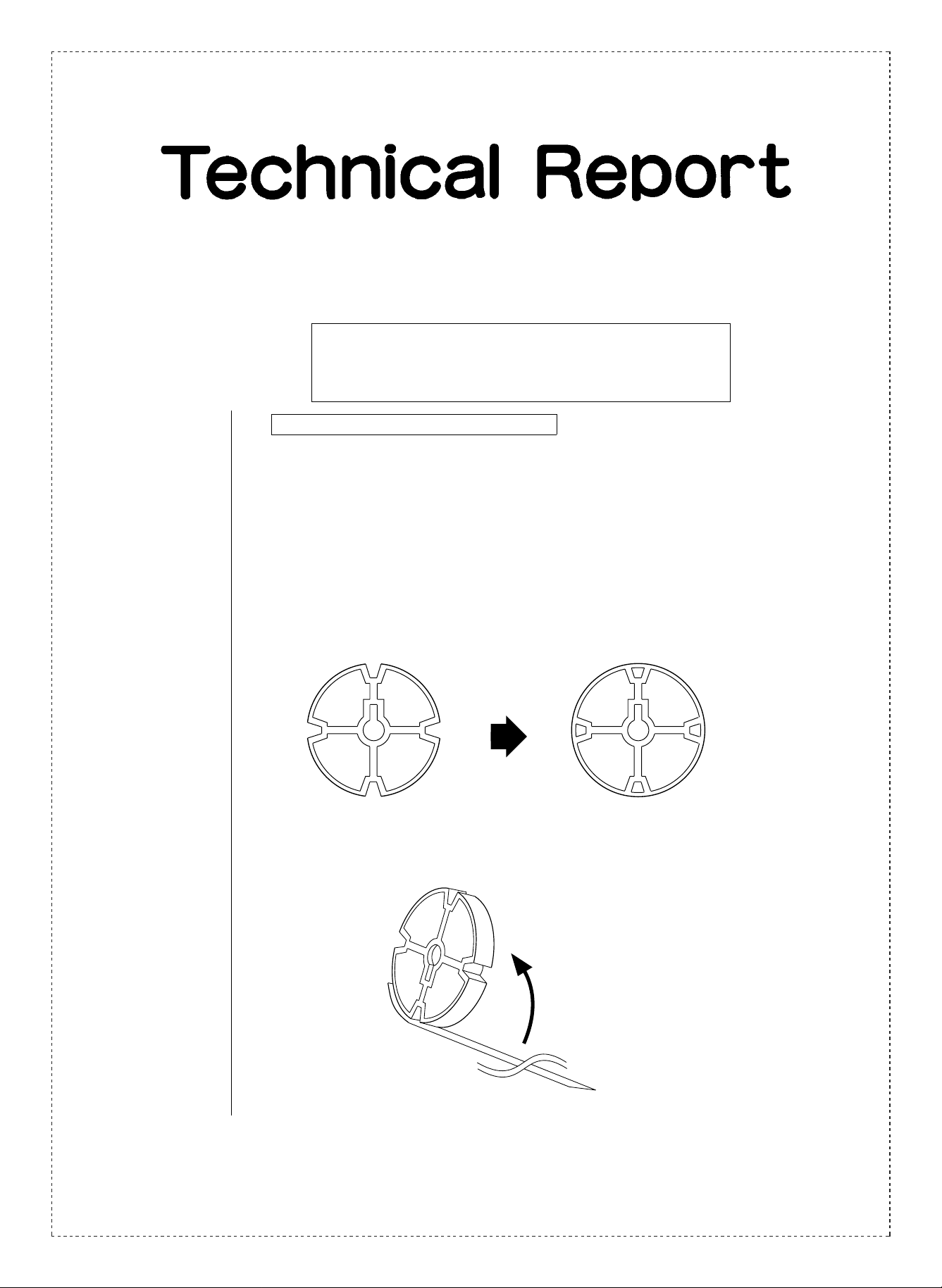
1. Prevention of jams in the finisher section.
1.General: During stapling operations, the copy paper sometimes becomes caught in the grooves
in the rear paddler collar, causing a jam to occur. To alleviate this problem, the grooves
in the paddler collar have been filled in to prevent the copy papers from becoming
caught. (The paddler collars in the front side use the same parts, and are to be
changed by means of running change.)
2.Description: A change in the shape of the paddler collars (filling in of the groves on the collars) has
been carried out as shown in the figures below.
Old New
PCLR-0395FCZZ PCLR-0395FCZ1
Note:As a temporary measure, a sheet has been at tached to the rear paddler collars.
SHARP CORPORATION Reprography Division
1/5
Green
C
Page 2
3.Action: (Factory action)
Temporary measure: From the start of mass production.
Change in rear paddler collar: From 1993 December production.
Change in front paddler collar: Running change from 1994 May production.
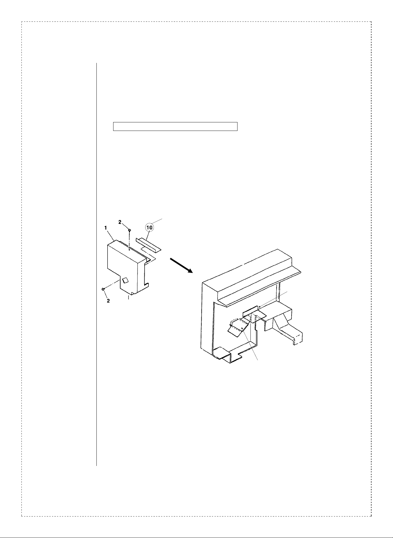
2. Change in cover sheet of the fini sher PWB.
1.General: The PWB cover sheet attached to the inside of the finisher PWB cover sometimes
peels and comes in contact with the jogger rack. To alleviate this problem, the PWB
cover sheet has been changed and two separate PWB cover sheets have been
employed.
2.Description: As shown in the figure below, the PWB cover sheet has been changed from one PWB
cover sheet to two separate PWB cover sheets: PWB cover sheet A and B.
Changed PWB sheet
PWB cover sheet A
(PSHEP3663FCZZ)
PWB cover sheet B
(PSHEP3664FCZZ)
2/5
Page 3

Finisher PWB cover
(FCOYP1220FCZZ)
Align
Tolerance
±0.5
<PWB cover sheet attachment standard.>
Tolerance
±0.5
Align
PWB cover sheet B
(PSHEP3664FCZZ)
PWB cover sheet A.
1. Align the curved line of the PWB cover
sheet with standard A .
2. Align the double sided tape line of the PWB
cover sheet with standard B .
PWB cover sheet A
(PSHEP3663FCZ)
Alignment
tolerance ± 0.5
Alignment
tolerance ± 3
Finisher PWB cover
(PCOYP1220FCZZ)
Outside face
PWB cover sheet B
PWB cover sheet B.
1. Align the curved line of the PWB cover
sheet on the inside face of the finisher PWB
cover with edge surface C of the hole in the
finisher PWB cover.
2. Align the curved line of the PWB cover
sheet on the inside face of the finisher PWB
cover with edge surface D of the hole in the
finisher PWB cover.
Inside face
3.Action: (Factory action)
Running change from 1993 December production.
3/5
Page 4

3. Change in spacer in the top of the sub paper guide.
1.General: Variance within the tolerance of the spacers used to control the later al movem ent of the
top of the sub paper guide sometimes causes the movement of the top of the sub paper
guide to be stiff. To alleviate this problem the spacers have been changed.
2.Description: The spacer in the rear frame side of the finisher frame unit (wave washer, flat washer)
has been changed (two flat washers).
P/G No. 98 LX-WZ0057FCZZ
P/G No. 100 LX-WZ0096FCZZ
The wave washer and flat washer combination assembly has been
changed to an assembly consisting of two (2) flat washers.
LX-WZ0016FCZZ Q’ty: 2
* The wave washer (LX-WZ0057FCZZ) shown in position No. 98 in the figure above is
used in other locations inside the finisher frame unit.
3.Action: (Factory action)
From 1994 January production.
4. Change in the tray frame of the finisher (parts guide correction).
1.General: A change in the tray frame of the finisher has been carried out from the start of mass
production. In accordance with this change, a correction in the parts guide is necessary
as shown below.
2.Description: Tray frame: LFRM-0798FCZ2 LFRM-0798FCZ3
4/5
Page 5

3.Action: (Factory action)
From the start of mass production.
5. Change in the operation manual for machines bound for the United Kingdom
(U.K. on ly).
1.General: The operation manual for machines bound for the United Kingdom has been changed
to the standard English operation manual used for machines bound for other English
speaking countries, to establish interchangeability.
2.Description: The parts code for the operation manual has been changed as shown below.
TINSE1 116FCZZ TINSE1 117FCZZ
3.Action: (Factory action)
From 1994 April production.
Ref.
Model
No.
1
2
SD-3062
3
4
5 U.K. 86 -37 TINSE1116FCZZ TINSE1117FCZZ AX
<Interchange>
1. Interchang ea bl e. 4. N ot i nt erc h an ge ab l e.
2. Current type can be used in place of new type.
New type cannot be used in place of current type.
3. Current type cannot be used in place of new type.
New type can be used in place of current type.
Parts marked with “ ” is important for maintaining the safety of the set. Be sure to replace these parts with
sp ec i fie d ones fo r m ai n ta ini ng t he safe ty an d pe r fo rma nc e o f the set .
name
Version P/G No.
50 -114 PCLR-0395FCZZ PCLR-0395FCZ1 AE Paddler collar
47 -10 PSHEP3627FCZZ
All
50 -98 LX-WZ0057FCZZ Q’ty change — Flat washer
50
50 -100 LX-WZ0096FCZZ LX-WZ0016FCZZ AB Washer Q’ty: 1
55 -32 LFRM-0798FCZ2 LFRM-0798FCZ3 BA Tray frame 1st lot. 1
!
Current parts New parts
Parts code Parts code
PSHEP3663FCZZ AC
PSHEP3664FCZZ AE
— LX-WZ0016FCZZ AB Washer Q’ty: 1
Price
5. Interchangeable if replaced with same types of
relate d parts in use .
6. Ot hers.
Parts name
rank
PWB cover
sheet A
PWB cover
sheet B
Operation
manual
Effec-
tive
time
See
text.
’94/1 5
’94/4 1
Inter-
change-
ability
6
5
Note
Q’ty:
2 to 1
5/5
 Loading...