

Page 1
Date: Jan. 24, 1994
DUPLICATOR: SD-2060
No. : DTE-126
TROUBLE SHOOTING ORIGINAL PAPER JAMS
IN THE OPTICAL AREA OF THE MACHINE.
1.Model name: SD-2060
2.General: When using the RADF, and especially when using thin original paper, the original paper
sometimes gets caught between the original stopper and the table glass. This problem
is generally caused by double feeding or by unevenness of the leading edge of the
original. The space between the table glass and the original stopper has been
narrowed, preventing this problem from occurring.
3.Cause: To prevent cams of the original paper in the optical area of the machine.
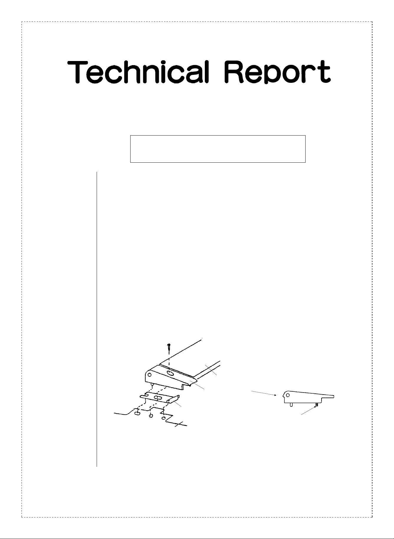
4.Description: The stopper bearing has been changed and a stopper adjustment plate has been
added. In carrying this out, the space between the copy table glass and the original
stopper has be decreased from the previous 0.3 ~ 0.5 mm to 0.08 ~ 0.1 mm, effectively
preventing the front edge of the original paper from becoming caught between the table
glass and the original stopper.
Note: Adjustment of the space between the table glass and the original spacer should
always be carried out (adjustment procedure is set forth under the section, “Field
action”, described below.)
Original stopper.
Stopper bearing
(changed).
Stopper adjustment plate
(added).
This boss has been cut.
SHARP CORPORATION Reprography Division
1/4
Green
C
Page 2
5.Action: (Factory action)
From 1994 February production.
(Field action)
When the same problem as described above occurs in a machine that is already out
on the, the procedure described below should be followed, and the space between the
original stopper and the table class should be adjusted.
* When the original is on paper that is 50 g/m
should be used.
SD-2060
Trouble shooting procedure for original paper jams in the optical area of the machine.
➀ Remove the upper left cabinet (parts guide 1 - 23).
➁ Remove the copy table glass.
➂ Remove the original stopper and the stopper bearing (front and rear).
* The stopper bearing is no longer needed.
2
to 35 g/m2, the RADF thin paper mode
(Assembly order)
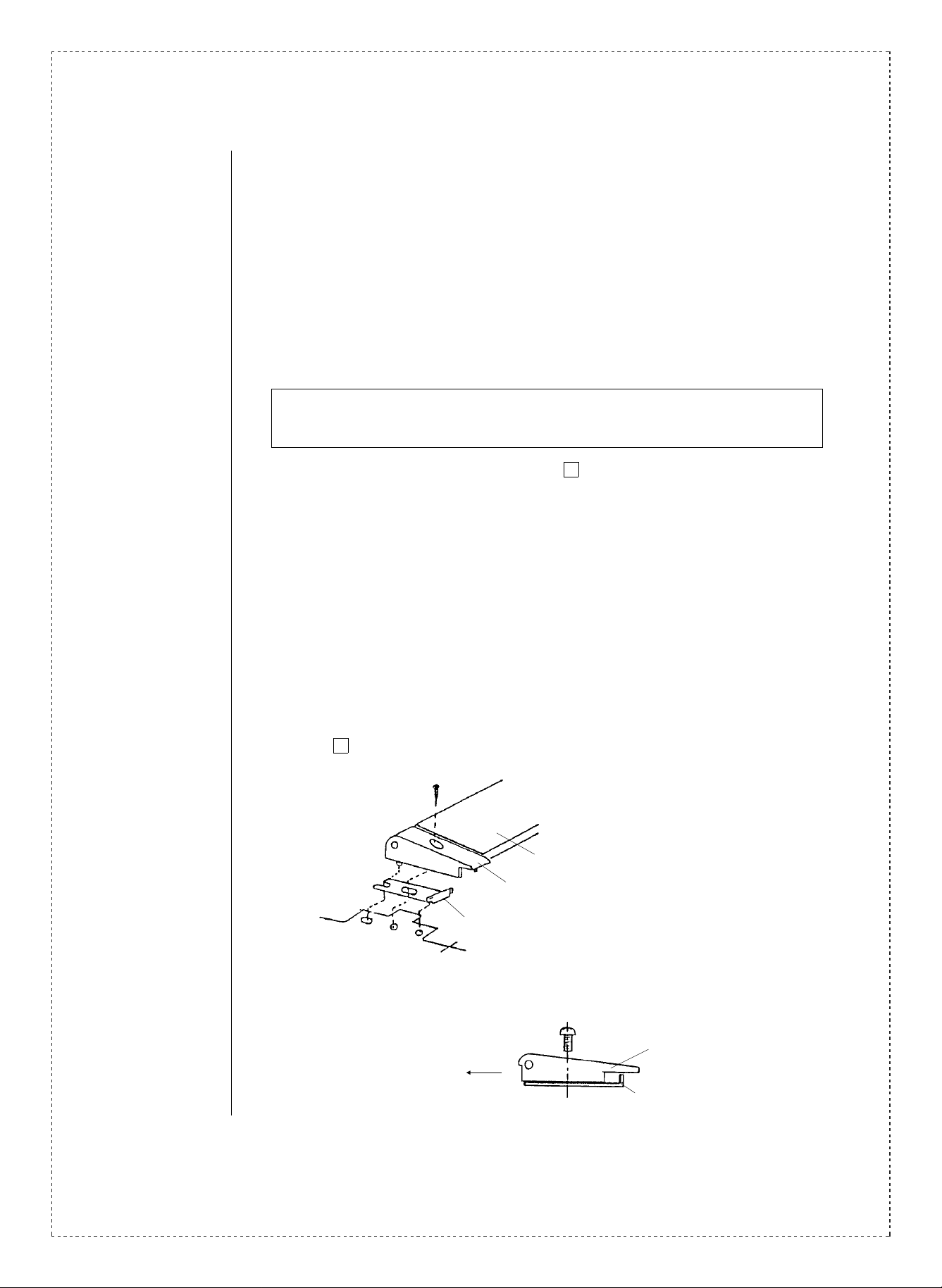
➃ Attach the changed stopper bearing and the stopper adjustment plate.
As shown in the illustration below, attach the stopper adjustment plate and the stopper
bearing on the front frame side. Next, the stopper adjustment plate and the stopper
bearing on the rear frame side should be attached while the original stopper is in the
attached position. Attach the rear frame stopper adjustment plate and the stopper
bearing to the attached front frame bearing, and after lifting the upper cabinet (parts
guide 1 - 19) it should be pushed into position.
Original stopper.
Stopper bearing.
Stopper adjustment plate.
➄ The stopper should be temporarily fixed. (fix the stopper as far as possible in the
direction shown below.
2/4
Stopper bearing.
Direction of copy paper output.
Stopper adjustment plate.
Page 3

➅ Exercising caution concerning the direction of the table glass, it should be fixed.
(The white painted edge of the table glass should be facing to the right front after
fixing.) At this time the stopper adjustment plate should be such that both F and R are
in line.
* Caution should be exercised. If hit too strongly the adjustment plate can become
deformed.
➆ Adjustment of the space between the table glass and the original stopper.
A4 size paper (thickness of 0.086 ~ 0.087) should be inserted between the original
stopper and the table glass. The stopper should then be pressed down and fixed.
After adjustment, check to see whether or not standard copy paper fits between the
original stopper and the table glass.
(Caution): If the temperature rises the space between the original stopper and the
table glass increases. As a result, when making adjustments the
temperature of the stopper should be checked. If it feels hot, the adjustment
should be set so that one sheet of standard paper can barely be squeezed
in between the original stopper and the table glass.
Under normal temperatures, adjustment should be carried out so that the
standard copy paper can’t quite be inserted, 40g/m paper just fits.
(Caution): When adjusting the original stopper, the stopper should not be adjusted
while in the lowered position (the space between the original stopper and
the table glass becomes too narrow).
(Caution): From F to R in the the original copy stopper and the copy table glass
should not be touching. Raise and lower the stopper manually to check.
(Caution): Check the height of the stopper. (It is is not correct, carry out the necessary
readjustments.)
1.0mm
Table glass.
Sim 2 - 3 - 8. Solenoid is
in the ON position.
Original stopper.
2.0mm
Table glass.
Free condition.
➇ Attach the upper left cabinet section.
3/4
Page 4

Ref.
Model
No.
1 SD-2060 All
<Interchange>
1. Interc ha ng ea bl e. 4. N ot i nt er ch an ge ab l e.
2. Current type can be used in place of new type.
New type cannot be used in place of current type.
3. Current type cannot be used in place of new type.
New type can be used in place of current type.
Parts marked with “ ” is important for maintaining the safety of the set. Be sure to replace these parts with
speci fied ones fo r m ai n ta in ing the safe ty an d pe r fo rmance of the set.
name
Version P/G No.
5 -13
5
!
Current parts New parts
Parts code Parts code
NBRGP0474FCZZ NBRGP0474FCZ1 AD Stopper bearing.
— LPLTM4540FCZZ AD
Price
5. Interchangeable if replaced with same types of
relate d parts in use .
6. Others.
Parts name
rank
Stopper
adjustment plate.
Effec-
tive
time
’94/2 5
Inter-
change-
ability
Note
Q’ty: 2
Q’ty: 2
4/4
 Loading...