

Page 1
Date: Dec. 2, 1993
DUPLICATOR : SD-2060
1. TROUBLESHOOTING COPY MISALIGNMENT BY GREASE APPLICATION TO THE FIXED
DRIVE BELT .
2. JAM TROUBLESHOOTING BY GREASE APPLICATION TO THE MIDDLE COPY PAPER TRAY
UNIT.
3. ELIMINATION OF IRREGULAR NOISE DURING DOUBLE SIDE COPY OPERATIONS.
No. : DTE-102
1. Troubleshooting copy misalignment by grease application to the fixed drive belt.
1.General: Dust from the drive belt connecting the main motor unit and the fixed drive unit sticks to
the 38 T pulley, causing copy misalignment trouble. To remedy this problem, the fixed
drive belt has been coated with white grease.
2.Description: A couple of spots of white grease are applied to the toothed edge (inner edge) of the
fixed drive belt a little at a time.
* 38 T Pulley (Fixed drive unit).
Idle
26 T
Fixed drive belt.
*
Apply a couple of spots of white grease
to the surface of each of the teeth.
30T
* 38 T Pulley.
Main Motor UN.
* When applying white grease after the unit has left the factory, check to make sure nothing
has stuck to the pulley. If debris or anything else is stuck to the pulley, it should be removed.
3.Effective time: (Factory action)
From 1993 mid-June production.
SHARP CORPORATION Reprography Division
1/5
Green
C
Page 2
2. JAM troubleshooting by grease application to the middle copy paper tray unit.
1.General: When the action of the moving paper guides of the middle copy paper feeding tray units
becomes heavy and dull, paper feeding jams can occur. This problem can be alleviated
by the application of grease to the middle copy paper feeding tray unit to make the
action of the moving paper guides work more sm oothly.
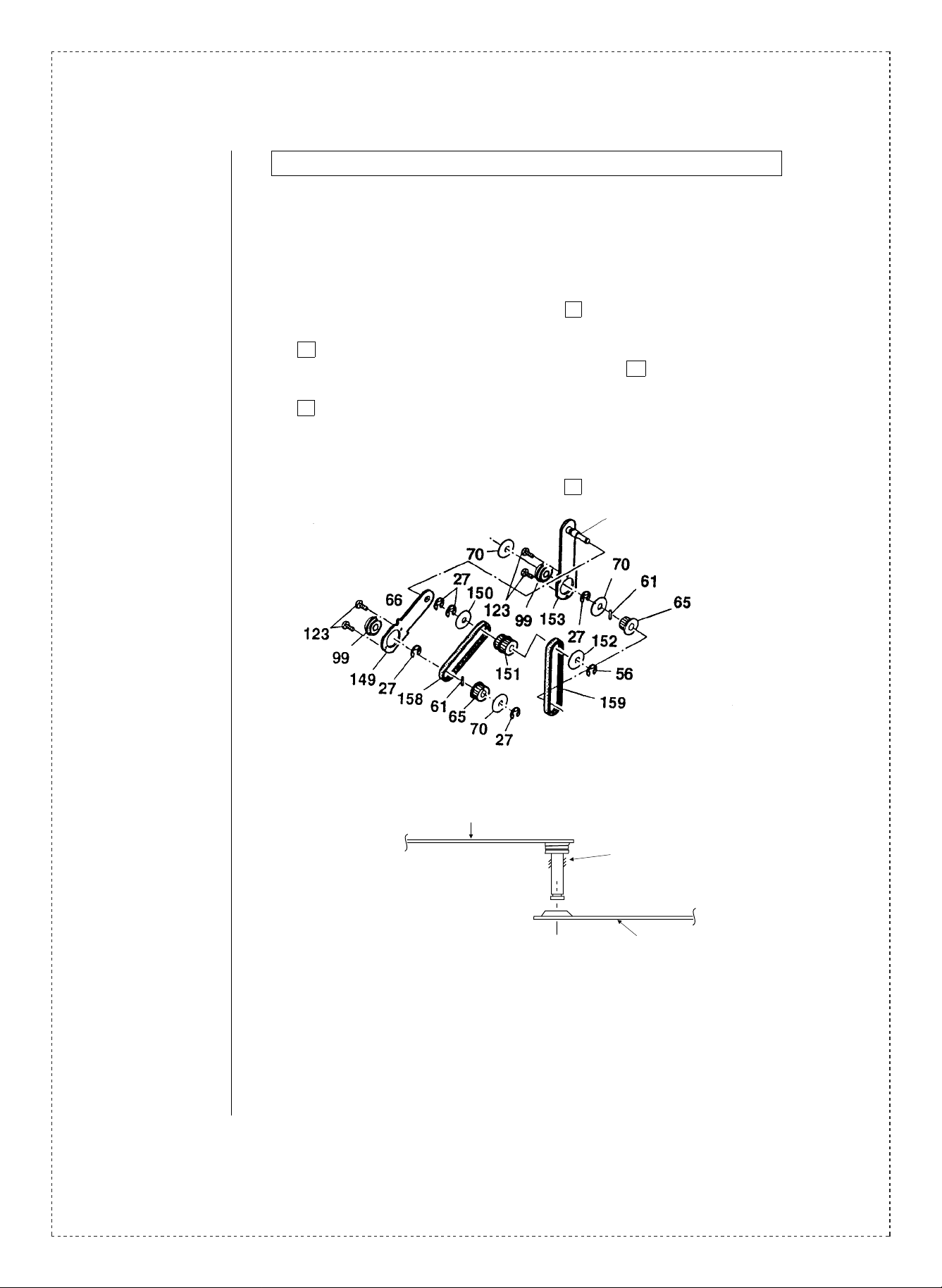
2.Description: 1. Apply grease to the pulley plate B (P/G No. 31 -153) shaft.
2. Apply grease to the bottom surface of the adjusting attachment plate (P/G No.
29 -39).
3. Apply grease to the copy paper feeding tray (P/G No. 29 -53).
4. Apply grease to the upper surface of the moving middle paper guides (P/G No.
31 -17).
* Use only UKOG-0158FCZZ grease.
1. Apply grease to the pulley plate B (P/G No. 31 -153) shaft.
Apply grease to this part.
2/5
Pulley plate B.
Apply a small spot of
grease to this area.
Pulley plate A.
Page 3

2. Apply grease to the bottom surface of the adjusting attachment plate (P/G No.
29 -39).
Apply grease to the shaded area.
Spacers.
39
30mm
Apply grease to
the shaded area.
Apply grease to the bottom surface of the adjusting attachment plate spacers and the
inside edge of the moving unit (4 places). Apply a few spots of grease per each 30 mm
area.
3. Apply grease to the copy paper feeding tray (P/G No. 29 -53).
Apply grease.
Apply a spot of grease to the bottom of the groove approximately 20 to 50 mm from
the back edge of the tray (1 place). Test slide the moving paper guide, and remove
any grease that oozes out of the groove.
3/5
Page 4

4. Apply grease to the upper surface of the moving middle paper guides (P/G No.
31 -17).
Apply a couple of spots of grease
Side surface.
to the protruding portion of the front
(4 places).
Upper surface.
Side surface.
Apply a couple of spots of grease to each of the upper and side surfaces.
3.Effective time: (Factory action)
1. From the start of mass production.
2. From the start of mass production.
3. From 1993 August production.
4. From 1993 June production.
3. Elimination of irregular noise during double side copy operations.
1.General: Irregular noise caused by scraping of burrs on the upper roller plate on the fixed side in
the middle copy paper tray unit sometimes occurs during double side copy operations.
To alleviate this problem, the return direction of the upper roller plate on the fixed side in
the middle copy paper tray unit has been reversed.
2.Reason: To alleviate the problem of irregular noise during double side copy operations.
3.Description: Contact with the roller is prevented by changing the return direction of the upper roller
plate of the fixed side. In order to distinguish between before- and after-change units, a
cutaway section has been added.
Note: as a temporary measure, the removal of the burrs has been taking place since
1993 mid-June production.
4/5
Page 5

Current
New
Fixed side upper roller.
Change
Fixed side upper roller.
(LPLTM4287FCZZ)
The return of this part was on
the inside, causing contact to be
made with the roller.
4.Effective time: Temporary: From 1993 mid-June production.
Permanent: From 1993 September production.
Ref.
Model
No.
SD-2060 All
<Interchange>
1. Intercha ng ea bl e. 4. N ot i nt er ch an ge ab l e.
2. Current type can be used in place of new type.
New type cannot be used in place of current type.
3. Current type cannot be used in place of new type.
New type can be used in place of current type.
Parts marked with “ ” is important for maintaining the safety of the set. Be sure to replace these parts with
specified on es for m ain ta in i ng t he s a fe ty an d pe rf o rma nc e o f th e s et .
name
Version P/G No.
31 -6 LPLTM4287FCZZ LPLTM4287FCZ1 AD
!
Current parts New parts
Parts code Parts code
Added cutaway section.
The return direction has been set
to the outside, and a cutaway
section has been added.
(LPLTM4287FCZ1)
Effec-
Price
5. Interchangeable if replaced with same types of
relate d parts in use .
6. Others.
Parts name
rank
Fixed side upper
roller plate.
tive
time
See
text.
Inter-
change-
ability
3
Note
5/5
 Loading...