

Page 1
Date: Nov. 19, 1993
DUPLICATOR : SD-2060
1.PREVENTION OF COPY IMAGE DISALIGNMENT DURING PRINTING.
2.PREVENTION OF LCD CORNER FADING BY CHANGING THE LIQUID
CRYSTAL ATTACHMENT PLATE.
3.PREVENTION OF WRINKLING DURING BACK SIDE COPYING.
No. : DTE-099
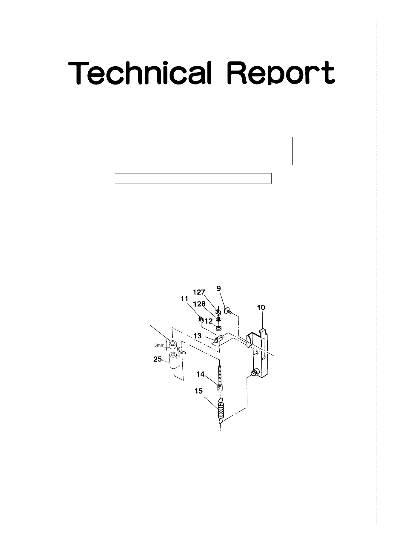
1. Prevention of copy image disalignment during printing.
1.General: Copy image disalignment sometimes occurs during the paper gripping process of the
heat rollers. To prevent this the pressure of the heat rollers has been reduced.
2.Cause: The above problem is caused by the impact during the paper gripping process of the
heat rollers.
3.Description: To reduce the pressure of the heat rollers and thus make the paper gripping process
run more smoothly, a collar has been added. (The collar has been added to both front
and rear sides of the fixer unit.)
Added collar
(PCLR-0391FCZZ).
4.Effective time: (Factory action)
From mid-July, 1993.
SHARP CORPORATION Reprography Division
This diagram is of the front side
of the fixer unit.
1/4
Green
C
Page 2
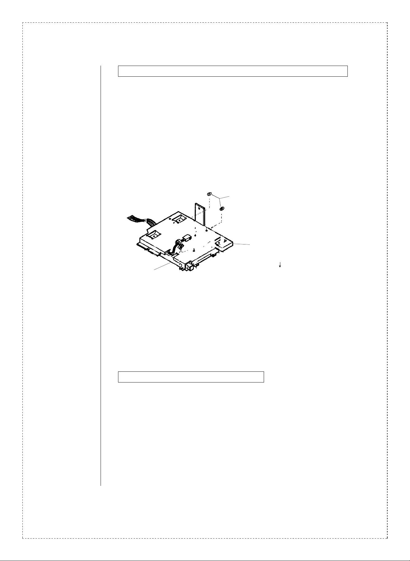
2. Prevention of LCD corner fading by changing the liquid crystal attachment plate.
1.General: A plastic washer with a thickness of 0.5 mm had been inserted between the LCD and
the liquid crystal attachment plate. To prevent fading of the liquid crystal display
corners, the shape of the liquid crystal attachment plate has been changed, and the use
of the washer has been discontinued.
2.Cause: The above change has been implemented as a permanent measure to prevent fading
of the LCD corners.
3.Description: Instead of using the plastic washer, the liquid crystal attachment plate has been tapered
0.5 mm. The parts codes affected by this have been changed accordingly.
A plastic washer with a thickness of 0.5
mm had been inserted between the LCD
and the liquid crystal attachment plate, but
the liquid crystal attachment plate has
been tapered 0.5 mm, and the use of the
plastic washer has been discontinued.
26
Liquid crystal attachment plate.
LPLTM4212FCZZ
24 (LCD)
LPLTM4212FCZ1
4.Effective time: (Factory action)
Addition of the 0.5 mm plastic washer:
From June, 1993.
Shape change of the liquid crystal attachment plate:
From October, 1993.
3. Prevention of wrinkling during back side copying.
1.General: Wrinkles sometimes occur during double side copying, caused by the formation of
moisture on the paper guides in the paper discharge unit. To remedy this problem,
ventilation holes have been added to the upper 2 paper guides and the lower paper
guides of the paper discharge unit, and the fixed supplementary paper guides have
been altered.
2.Cause: Moisture which forms on the paper guides is absorbed by the copy paper when being
discharged. When this damp paper is double side copied, it has a tendency to wrinkle.
In particular, when copying on damp paper, the moisture is vaporized and then forms on
the paper guides, causing wrinkles.
2/4
Page 3

3.Description: Ventilation holes have been added to the upper 2 paper guides and the lower paper
guides of the paper discharge unit to prevent the formation of moisture.
Moreover, the shape of the fixed supplementary paper guides has been altered. These
measures are designed to prevent the wrinkling of the copy paper when both sides are
copied.
Changed lower paper guides of the paper discharge unit.
Added ventilation holes.
Changed upper 2 paper guides
of the paper discharge unit.
Added ventilation holes.
Before change.
Paper guide A.
Fixed supplementary paper guides.
Method of distinguishing between old and new fixed supplementary paper guides.
Before change. After change.
After change.
(The new fixed supplementary paper guides
are slightly more curved than the old ones.)
3/4
Page 4

With this change the attachment position of the paper guide FA fixer unit has changed.
1) The F/R paper guide positioning plate is aligned with the top indicators of the Fu
frame F/R, and secured with screws. (originally center)
2) The paper guide FA is attached to the lower portion of the paper guide positioning
plate without clearance.
Fu frame F.
Paper guide
positioning plate F.
4.Effective time: (Factory action)
From September, 1993.
Ref.
Model
No.
1
2
SD-2060 All
3
<Interchange>
1. Interchangeable. 4. Not interchangeable.
2. C urr e nt t y pe c a n be u s ed i n p la ce of new ty pe .
New ty pe cann ot be us ed i n place of curr ent type .
3. C urre nt ty pe cann ot be used i n place of new ty pe.
New t y pe c a n be u sed in p la ce of curr en t ty p e.
Parts m ar ke d wi t h “ ” is i mpor t an t fo r m a in ta i ning t he s a fe ty of the s e t. B e su r e to re pl ace these pa rts wi t h
specified ones for maintaining the safety and performance of the set.
name
Version P/G No.
Aligned with the top indicators
of the P/G positioning plate.
Paper guide FA.
Current parts New parts
Parts code Parts code
11 — PCLR-0391FCZZ AA
2 -26
15 -38 PGIDH1461FCZZ PGIDH1461FCZ1 AN
15 -22 PGIDH1437FCZZ PGIDH1437FCZ1 AT
11 -107 PGIDH1476FCZZ PGIDH1476FCZ1 AS
!
LPLTM4212FCZZ LPLTM4212FCZ1 AP
Price
rank
5. Interchangeable if replaced with same types of
relate d parts in use .
6. Others.
Parts name
Holder fixing
collar.
Liquid crystal
attachment plate.
Upper 2 paper
guides of the paper
discharge unit .
Lower paper
guides of the paper
discharge unit.
Fixed supplement
paper guide.
Fu frame R.
Paper guide
positioning plate R.
Effec-
Inter-
tive
change-
time
Mid-
Jul.
1993
’93/10 3
’93/9
Note
ability
—
3
3
3
4/4
 Loading...