

Page 1
SERVICE MANUAL
S95N7DT-100//
MULTIMEDIA PROJECTOR
DT-100
MODEL DT-100
In the interests of user-safety (Required by safety regulations in some countr ies) the set should be restored to its original condition and only parts identical to those specified should be used.
SHARP CORPORATION
This document has been published to be used for
after sales service only.
The contents are subject to change without notice.
Page 2

DT-100
• SPECIFICATIONS ............................................3
• IMPORTANT SERVICE SAFETY
NOTES (for USA)..............................................4
• NOTE TO SERVICE PERSONNEL ..................6
• OPERATION MANUAL ...................................10
• DIMENSIONS ................................................. 16
• RESETTING THE TO TAL LAMP TIMER .........17
• REMOVING OF MAJOR PARTS.....................19
• THE OPTICAL UNIT OUTLINE ......................22
• ELECTRICAL ADJUSTMENT .........................24
• TROUBLE SHOOTING TABLE ....................... 30
• BLOCK DIAGRAM ..........................................40
CONTENTS
Page Page
• OVERALL WIRING DIAGRAM........................42
• DESCRIPTION OF SCHEMATIC DIAGRAM .. 44
• WAVEFORMS ................................................. 45
• SCHEMATIC DIAGRAM..................................46
• PRINTED WIRING BOARD ASSEMBLIES..... 74
• PARTS LIST
Ë
ELECTRICAL PARTS.................................94
Ë
CABINET AND MECHANICAL PARTS ....105
Ë
ACCESSORIES PARTS...........................109
Ë
PACKING PARTS.....................................109
• PACKING OF THE SET ................................110
2
Page 3

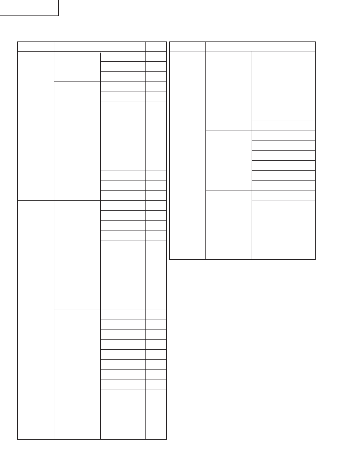
SPECIFICATIONS
DT-100
Product type
Model
Video system
Display method
DMD panel
Lens
Projection lamp
Component input signal
(INPUT1/2)
Horizontal resolution
Computer RGB input
(INPUT 1/2)/output
(OUTPUT) signal
S-video input signal
(INPUT 3)
Video input signal
(INPUT 4)
Ver tical frequency
Horizontal frequency
Pixel clock
RS-232C terminal
Audio input signal
Audio output signal
(AUDIO OUTPUT 1-4)
Speaker system
Rated voltage
Input current
Rated frequency
Power consumption
Power consumption (standby)
Heat dissipation
Operating temperature
Storage temperature
Cabinet
I/R carrier frequency
Dimensions (approx.)
Weight (approx.)
Replacement parts
Projector
DT-100
NTSC3.58/NTSC4.43/PAL/PAL-M/PAL-N/PAL-60/SECAM/DTV480I/DTV480P/
DTV540P/DTV576I/DTV576P/DTV720P/DTV1035I/DTV1080I/DTV1080I-50
Single Chip Digital Micromirror Device
Panel size:
No. of dots:
1–1.15 zoom lens, F2.4–2.6, f = 19.0–21.9 mm
×
"
, 1chipDMD
0.53
409,920 dots (854 [H] 480 [V])
TM
(DMDTM) by Texas Instruments
×
275 W DC lamp
15-pin mini D-sub connector
Y: 1.0 Vp-p, sync negative, 75 terminated
P
: 0.7 Vp-p, 75 terminated
B
P
: 0.7 Vp-p, 75 terminated
R
Ω
Ω
Ω
520 TV lines (DTV720P)
15-pin mini D-sub connector
RGB separate/sync on green type analog input: 0–0.7 Vp-p , positive, 75 terminated
Ω
HORIZONTAL SYNC. SIGNAL: TTL level (positive/negative)
VERTICAL SYNC. SIGNAL: Same as above
4-pin mini DIN connector
Y (luminance signal): 1.0 Vp-p, sync negative, 75 terminated
C (chrominance signal): Burst 0.286 Vp-p, 75 terminated
RCA connector: VIDEO, composite video, 1.0 Vp-p, sync negative, 75
Ω
Ω
Ω
terminated
45–85 Hz
15–70 kHz
12–108 MHz
9-pin mini DIN connector
ø3.5 mm minijack or RCA terminal: 0.5 Vrms, more than 22 k (stereo)
ø3.5 mm minijack: 0.5 Vrms, less than 2.2 k
4 cm 2.85 cm oval 1
××
Ω
Ω
AC 100–240 V
3.6 A
50/60 Hz
350 W (Lamp Setting “Bright”)/
305 W (Lamp Setting “Eco + Quiet”)
with AC 100 V
330 W (Lamp Setting “Bright”)/
285 W (Lamp Setting “Eco + Quiet”)
with AC 240 V
4 W (AC 100 V) – 5 W (AC 240 V)
1,315 BTU/hour (Lamp Setting “Bright”)/
1,145 BTU/hour (Lamp Setting “Eco + Quiet”) with AC 100 V
1,240 BTU/hour (Lamp Setting “Bright”)/
1,070 BTU/hour (Lamp Setting “Eco + Quiet”) with AC 240 V
41°F to 95°F (+5°C to +35°C)
–4°F to 140°F (–20°C to +60°C)
Plastic
38 kHz
13
12
12
×
/32" 4 19/64" 11 1/32" (315 (W) 109 (H) 280 (D) mm) (main body only)
13
/32" 4 47/64" 11 37/64" (315 (W) 120 (H) 294 (D) mm) (including adjust-
×
×
×
×
×
×
×
ment foot and projecting parts)
8.6 lbs. (3.9 kg)
Remote control, Power cord for U.S. and Canada,
3 RCA to 15-pin D-sub adaptor, Operation manual
As a part of policy of continuous improvement, SHARP reserves the right to make design and
specification changes for product improvement without prior notice. The performance specification figures indicated are nominal values of production units. There may be some deviations from
these values in individual units.
3
Page 4
DT-100
2
2
IMPORTANT SERVICE SAFETY NOTES (for USA)
Ë Service work should be performed only by qualified service technicians who are
thoroughly familiar with all safety checks and servicing guidelines as follows:
WARNING
1. For continued safety, no modification of any circuit
should be attempted.
2. Disconnect AC power before servicing.
» Use an AC voltmeter with sensitivity of 5000 ohm per
volt., or higher, sensitivity to measure the AC voltage
drop across the resistor (See Diagram).
» All checks must be repeated with the AC plug
connection reversed. (If necessary, a non-polarized
adapter plug must be used only for the purpose of
BEFORE RETURNING THE PROJECTOR:
(Fire & Shock Hazard)
Before returning the projector to the user, perform
the following safety checks:
1. Inspect lead wires are not pinched between the chassis
completing these checks.)
Any reading of 0.3 volts RMS (this corresponds to 0.2
milliamp. AC.) or more is excessive and indicates a
potential shock hazard which must be corrected before
returning the unit to the owner.
and other metal parts of the projector.
2. Inspect all protective devices such as non-metallic
control knobs, insulating materials, cabinet backs,
DVM
AC SCALE
adjustment and compartment covers or shields,
isolation resistor-capacity networks, mechanical
insulators, etc.
1.5k ohm
10W
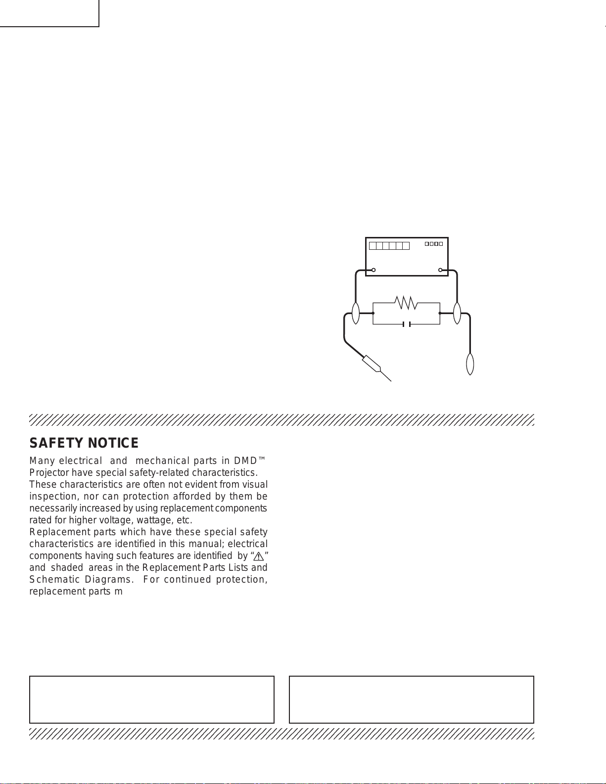
3. To be sure that no shock hazard exists, check for
current leakage in the following manner:
» Plug the AC cord directly into a 120-volt AC outlet, (Do
not use an isolation transformer for this test).
0.15 µF
TEST PROBE
» Using two clip leads, connect a 1.5k ohm, 10 watt
resistor paralleled by a 0.15µF capacitor in parallel
between all exposed metal cabinet parts and earth
ground.
234567890123456789012345678901212345678901234567890123456789012123456789012345678901234567890121
TO EXPOSED
METAL PARTS
CONNECT TO
KNOWN EARTH
GROUND
SAFETY NOTICE
Many electrical and mechanical parts in DMD™
Projector have special safety-related characteristics.
These characteristics are often not evident from visual
inspection, nor can protection afforded by them be
necessarily increased by using replacement components
rated for higher voltage, wattage, etc.
Replacement parts which have these special safety
characteristics are identified in this manual; electrical
components having such features are identified by “å”
and shaded areas in the Replacement Parts Lists and
Schematic Diagrams. For continued protection,
replacement parts must be identical to those used in
the original circuit. The use of a substitute replacement
parts which do not have the same safety characteristics
as the factory recommended replacement parts shown
in this service manual, may create shock, fire or other
hazards.
AVIS POUR LA SECURITE
De nombreuses pièces, électriques et mécaniques, dans
les projecteur à DMD™ présentent des caractéristiques
spéciales relatives à la sécurité, qui ne sont souvent pas
évidentes à vue.
Le degré de protection ne peut pas être nécessairement
augmentée en utilisant des pièces de remplacement
étalonnées pour haute tension, puissance, etc.
Les pièces de remplacement qui présentent ces
caractéristiques sont identifiées dans ce manuel;
les pièces électriques qui présentent ces particularités
sont identifiées par la marque “å” et hachurées dans la
liste des pièces de remplacement et les diagrammes
schématiques. Pour assurer la protection, ces pièces
doivent être identiques à celles utilisées dans le circuit
d’origine. L’utilisation de pièces qui n’ont pas les mêmes
caractéristiques que les pièces recommandées par l’usine,
indiquées dans ce manuel, peut provoquer des
électrocutions, incendies ou autres accidents.
WARNING: The bimetallic component has the primary
conductive side exposed. Be very careful in
handling this component when the power is on.
234567890123456789012345678901212345678901234567890123456789012123456789012345678901234567890121
AVERTISSEMENT:La composante bimétallique dispose du
conducteur primaire dénudé. Faire attention
lors de la manipulation de cette
composante sous tension.
4
Page 5
DT-100
PRECAUTIONS A PRENDRE LORS DE LA REPARATION
Ë
Ne peut effectuer la réparation qu' un technicien spécialisé qui s'est parfaitement
accoutumé à toute vérification de sécurité et aux conseils suivants.
AVERTISSEMENT
1. N'entreprendre aucune modification de tout circuit.
C'est dangereux.
2. Débrancher le récepteur avant toute réparation.
VERIFICATIONS CONTRE L'INCEN-DIE ET
LE CHOC ELECTRIQUE
Avant de rendre le récepteur à l'utilisateur, effectuer
les vérifications suivantes.
1. Inspecter tous les faisceaux de câbles pour s'assurer
que les fils ne soient pas pincés ou qu'un outil ne soit
pas placé entre le châssis et les autres pièces
métalliques du récepteur.
2. Inspecter tous les dispositifs de protection comme les
boutons de commande non-métalliques, les isolants, le
dos du coffret, les couvercles ou blindages de réglage
et de compartiment, les réseaux de résistance-capacité,
les isolateurs mécaniques, etc.
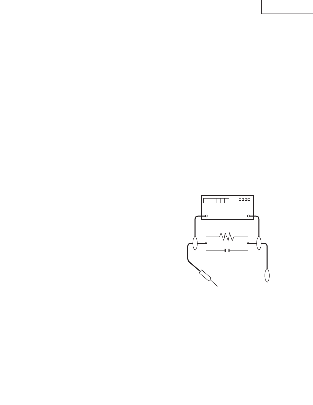
3. S'assurer qu'il n'y ait pas de danger d'électrocution en
vérifiant la fuite de courant, de la facon suivante:
• Brancher le cordon d'alimentation directem-ent à une
prise de courant de 110-240V. (Ne pas utiliser de
transformateur d'isolation pour cet essai).
• A l'aide de deux fils à pinces, brancher une résistance
de 1.5 kΩ 10 watts en parallèle avec un condensateur
de 0.15µF en série avec toutes les pièces métalliques
exposées du coffret et une terre connue comme une
conduite électrique ou une prise de terre branchée à la
terre.
• Utiliser un voltmètre CA d'une sensibilité d'au moins
5000Ω/V pour mesurer la chute de tension en travers
de la résistance.
• Toucher avec la sonde d'essai les pièces métalliques
exposées qui présentent une voie de retour au châssis
(antenne, coffret métallique, tête des vis, arbres de
commande et des boutons, écusson, etc.) et mesurer la
chute de tension CA en-travers de la résistance. T outes
les vérifications doivent être refaites après avoir inversé
la fiche du cordon d'alimentation. (Si nécessaire, une
prise d'adpatation non polarisée peut être utilisée dans
le but de terminer ces vérifications.)
Tous les courants mesurés ne doivent pas dépasser 0.5
mA.
Dans le cas contraire, il y a une possibilité de choc
électrique qui doit être supprimée avant de rendre le
récepteur au client.
DVM
ECHELLE CA
1.5k ohm
10W
5
AUX PIECES
METALLIQUES
EXPOSEES
0.15 µF
SONDE D'ESSAI
BRANCHER A UNE
TERRE CONNUE
Page 6
DT-100
NO TE TO SER VICE
PERSONNEL
UV-RADIATION PRECAUTION
The light source, UHP lamp, in the LCD projector
emits small amounts of UV-Radiation.
AVOID DIRECT EYE AND SKIN EXPOSURE.
To ensure safety please adhere to the following:
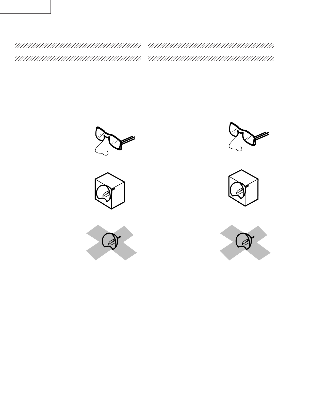
1. Be sure to wear sun-glasses when servicing the
projector with the lamp
turned “on” and the top
enclosure removed.
2. Do not operate the lamp outside of the lamp housing.
NOTE POUR LE PERSONNEL
D’ENTRETIEN
PRECAUTION POUR LES RADIATIONS UV
La source de lumière, la lampe UHP, dans le projecteur
LCD émet de petites quantités de radiation UV.
EVITEZ TOUTE EXPOSITION DIRECTE DES
YEUX ET DE LA PEAU.
Pour votre sécurité, nous vous prions de respecter
les points suivants:
1. T oujours porter des lunettes de soleil lors d’un entretien
du projecteur
avec la lampe allumée
et le haut du coffret retiré.
2. Ne pas faire fonctionner la lampe à l’extérieur du boîtier
de lampe.
3. Do not operate for more than 2 hours with the enclosure
removed.
UV-Radiation and Medium Pressure
Lamp Precautions
1. Be sure to disconnect the AC plug when replacing the
lamp.
2. Allow one hour for the unit to cool down before
servicing.
3. Replace only with same type lamp. Type AN-100LP
rated 275W DC.
4. The lamp emits small amounts of UV -Radiation, av oid
direct-eye contact.
5. The medium pressure lamp involves a risk of explosion.
Be sure to follow installation instructions described
below and handle the lamp with care.
3. Ne pas faire fonctionner plus de 2 heures av ec le coffret
retiré.
Précautions pour les radiations UV
et la lampe moyenne pression
1. Toujours débrancher la fiche AC lors du remplacement
de la lampe.
2. Laisser l’unité refroidir pendant une heure avant de
procéder à l’entretien.
3. Ne remplacer qu’avec une lampe du même type. Type
AN-100LP, caractéristique 275 W-DC.
4. La lampe émet de petites quantités de radiation UVéviter tout contact direct avec les yeux.
5. La lampe moyenne pression implique un risque
d’explosion. Toujours suivre les instructions
d’installation décrites ci-dessous et manipuler la lampe
avec soin.
6
Page 7
DT-100
6
6
6
6
2345678901234567890123456789012123456789012345
UV-RADIATION PRECAUTION (Continued)
2345678901234567890123456789012123456789012345
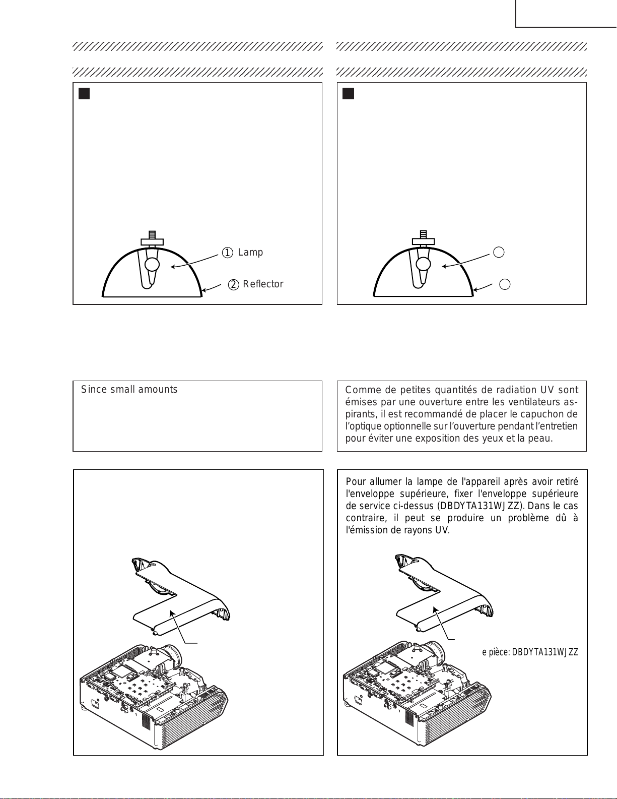
Lamp Replacement
Note:
Since the lamp reaches a very high temperature during
units operation replacement of the lamp should be
done at least one hour after the power has been turned
off. (to allow the lamp to cool off.)
Installing the new lamp, make sure not to touch the
lamp (bulb) replace the lamp by holding its reflector
2.
[Use original replacement only.]
Lamp
1
Reflector
2
DANGER ! –– Never turn the power on without the
lamp to avoid electric-shock or damage of the de vices
since the stabilizer generates high voltages at its start.
2345678901234567890123456789012123456789012345
PRECAUTION POUR LES RADIATIONS UV (Suite)
2345678901234567890123456789012123456789012345
Remplacement de la lampe
Remarque:
Comme la lampe devient très chaude pendant le
fonctionnement de l’unité, son remplacement ne doit
être effectué au moins une heure après avoir coupé
l’alimentation (pour permettre à la lampe de refroidir).
En installant la nouvelle lampe, s’assurer de ne pas
toucher la lampe (ampoule). Remplacer la lampe en
tenant son réflecteur 2.
[N’utiliser qu’un remplacement d’origine.]
1
Lampe
2
Reflecteur
DANGER ! –– Ne jamais mettre sous tension sans la
lampe pour éviter un choc électrique ou des
dommages des appareils car le stabilisateur génère
de hautes tensions à sa mise en route.
Since small amounts of UV-radiation are emitted
from an opening between the exhaust fans , it is recommended to place the cap of the optional lens on
the opening during servicing to avoid eye and skin
exposure.
To illuminate the lamp in the unit with Top Body
removed, attach the above Service Top Body
(DBDYTA131WJZZ). If not, problems may be caused
by UV light emitted from the lamp.
Top Body
Part code:DBDYTA131WJZZ
Comme de petites quantités de radiation UV sont
émises par une ouverture entre les ventilateurs aspirants, il est recommandé de placer le capuchon de
l’optique optionnelle sur l’ouverture pendant l’entretien
pour éviter une exposition des yeux et la peau.
Pour allumer la lampe de l'appareil après avoir retiré
l'enveloppe supérieure, fixer l'enveloppe supérieure
de service ci-dessus (DBDYTA131WJZZ). Dans le cas
contraire, il peut se produire un problème dû à
l'émission de rayons UV.
Enveloppe supérieur
Code de pièce:DBDYTA131WJZZ
7
Page 8
DT-100
WARNING: High brightness light source, do not stare into the beam of light, or view directly. Be especially
careful that children do not stare directly in to the beam of light.
WARNING: TO REDUCE THE RISK OF FIRE OR ELECTRIC SHOCK, DO NOT EXPOSE THIS UNIT TO
MOISTURE OR WET LOCATIONS.
CAUTION
RISK OF ELECTRIC SHOCK.
DO NOT REMOVE SCREWS
EXCEPT SPECIFIED USER
SERVICE SCREW.
CAUTION: TO REDUCE THE RISK OF ELECTRIC SHOCK,
DO NOT REMO VE CABINET.
NO USER-SERVICEABLE PARTS EXCEPT LAMP UNIT.
REFER SERVICING T O Q U ALIFIED SER VICE
PERSONNEL.
The lighting flash with arrowhead within a
triangle is intended to tell the user that
parts inside the product are risk of electric
shock to persons.
The exclamation point within a triangle is
intended to tell the user that important
operating and servicing instructions are in
the manual with the projector.
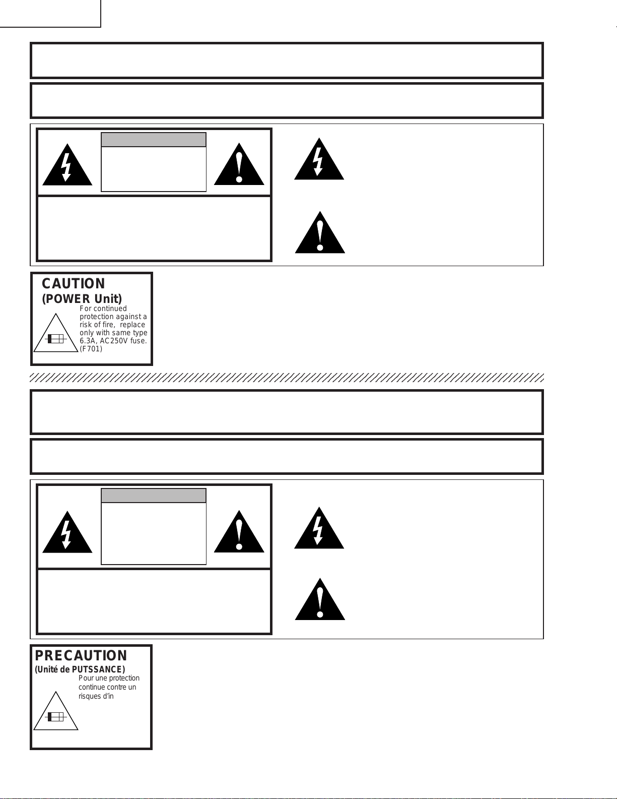
CAUTION
(POWER Unit)
6.3A 250V
AVERTISSEMENT: Source lumineuse de grande intensité. Ne pas fix er le faisceau lumineux ou le regarder
For continued
protection against a
risk of fire, replace
only with same type
6.3A, AC250V fuse.
(F701)
directement. Veiller particulièrement à éviter que les enfants ne fixent directement le
faisceau lumineux.
AVER TISSEMENT : AFIN D’EVITER TOUT RISQUE D’INCENDIE OU D’ELECTROCUTION, NE P AS PLA CER
CET APPAREIL DANS UN ENDROIT HUMIDE OU MOUILLE.
ATTENTION
RISQUE
D’ÉLECTROCUTION. NE
PASR ETIRER LES VIS Á
L’EXCEPTION DE LA VIS DE
REPARATION UTILISATEUR
SPECIFIEES
L’éclair ter miné d’une flèche à l’intérieur
d’un triangle indique à l’utilisateur que les
pi‘eces se trouvant dans l’appareil sont
susceptibles de provoquer une décharge
électrique.
Le point d’exclamation à l’intérieur d’un
ATTENTION: POUR EVITER T OUT RISQ UE
D’ELECTR OCUTION, NE PAS RETIRER LE CAPOT .
AUCUNE DES PIECES INTERIEURES N’EST REPARABLE
PAR L’UTILISATEUR, A L’EXCEPTION DE L’UNITE DE
LAMPE. POUR T OUTE REPARATION, S’ADRESSER A UN
TECHNICIEN D’ENTRETIEN QU ALIFIE.
triangle indique à l’utilisateur que les
instructions de fonctionnement et
d’entretien sont détaillées dans les
documents fournis avec le projecteur.
PRECAUTION
(Unité de PUTSSANCE)
6.3A 250V
Pour une protection
continue contre un
risques d’incendie, ne
remplacer qu’avec un
fusible 6.3A,AC250V
du même type.
(F701)
8
Page 9
DT-100
Precautions for using lead-free solder
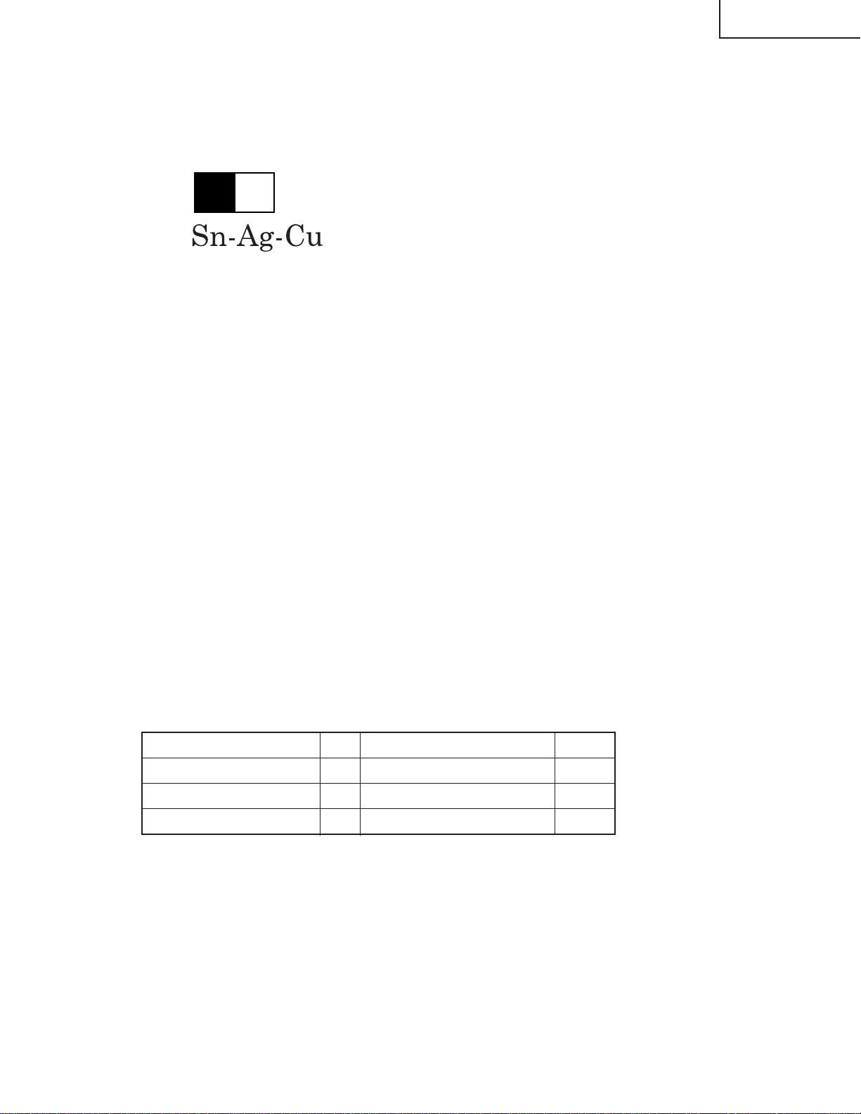
1 Employing lead-free solder
"PWBs" of this model employs lead-free solder. The LF symbol indicates lead-free solder, and is attached on the
PWBs and service manuals. The alphabetical character following LF shows the type of lead-free solder.
Example:
L Fa
Indicates lead-free solder of tin, silver and copper.
2 Using lead-free wire solder
When fixing the PWB soldered with the lead-free solder, apply lead-free wire solder. Repairing with conventional
lead wire solder may cause damage or accident due to cracks.
As the melting point of lead-free solder (Sn-Ag-Cu) is higher than the lead wire solder by 40°C, we recommend y ou
to use a dedicated soldering bit, if you are not familiar with how to obtain lead-free wire solder or soldering bit,
contact our service station or service branch in your area.
3 Soldering
As the melting point of lead-free solder (Sn-Ag-Cu) is about 220°C which is higher than the conventional lead solder
by 40°C, and as it has poor solder wettability, you may be apt to keep the soldering bit in contact with the PWB for
extended period of time. Ho we v er, since the land may be peeled off or the maximum heat-resistance temperature of
parts may be exceeded, remove the bit from the PWB as soon as you confirm the steady soldering condition.
Lead-free solder contains more tin, and the end of the soldering bit may be easily corroded. Make sure to tur n on
and off the power of the bit as required.
If a different type of solder stays on the tip of the soldering bit, it is allo yed with lead-free solder. Clean the bit after
every use of it.
When the tip of the soldering bit is blackened during use, file it with steel wool or fine sandpaper.
Be careful when replacing parts with polarity indication on the PWB silk.
Lead-free wire solder for servicing
Part No. ★ Description Code
ZHNDAi123250E J φ0.3mm 250g(1roll) BL
ZHNDAi126500E J φ0.6mm 500g(1roll) BK
ZHNDAi12801KE J φ1.0mm 1kg(1roll) BM
9
Page 10
DT-100
Operation Manual
10
Page 11
DT-100
11
Page 12
DT-100
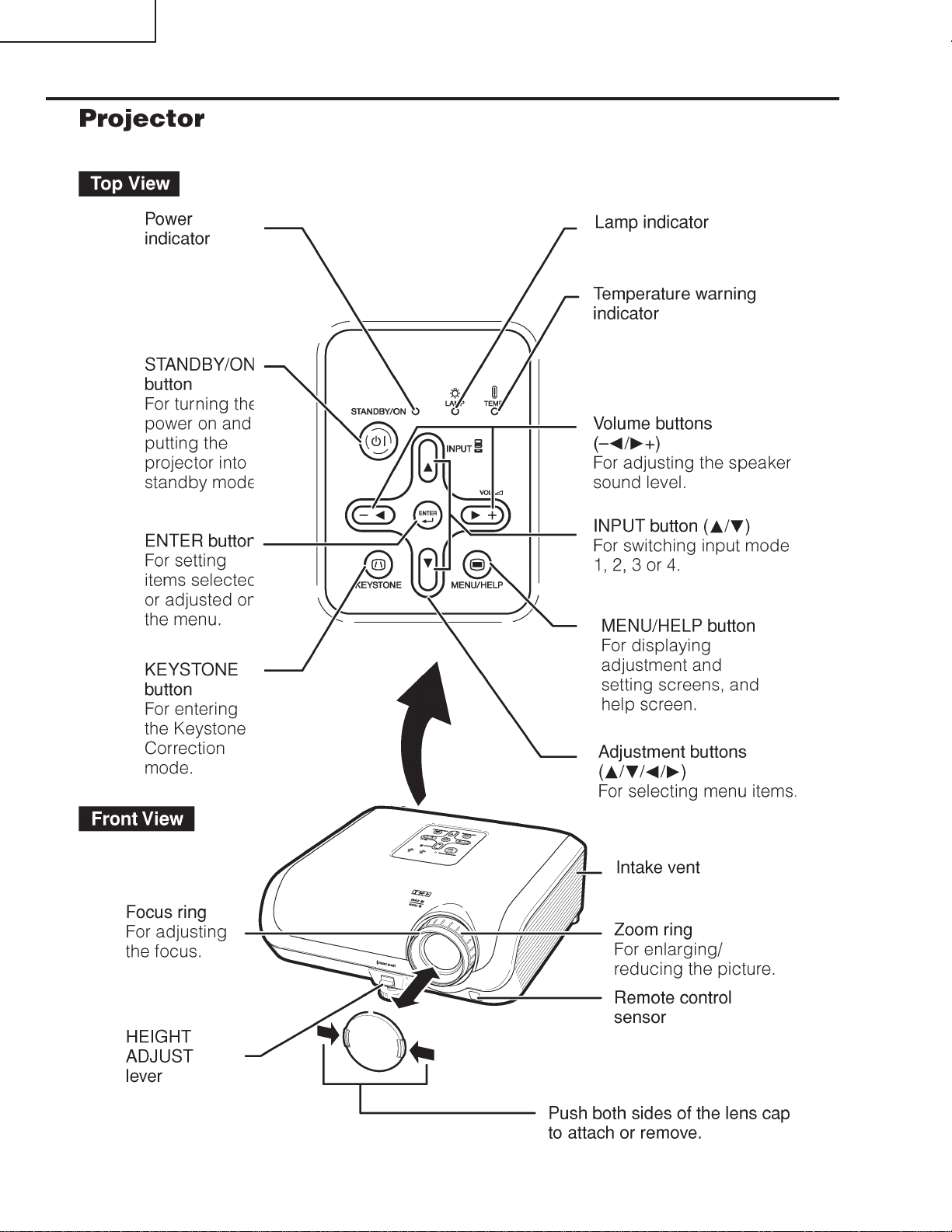
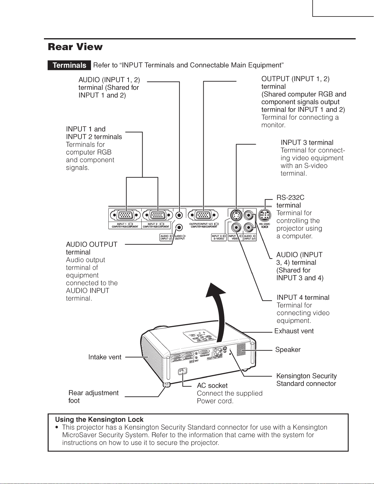
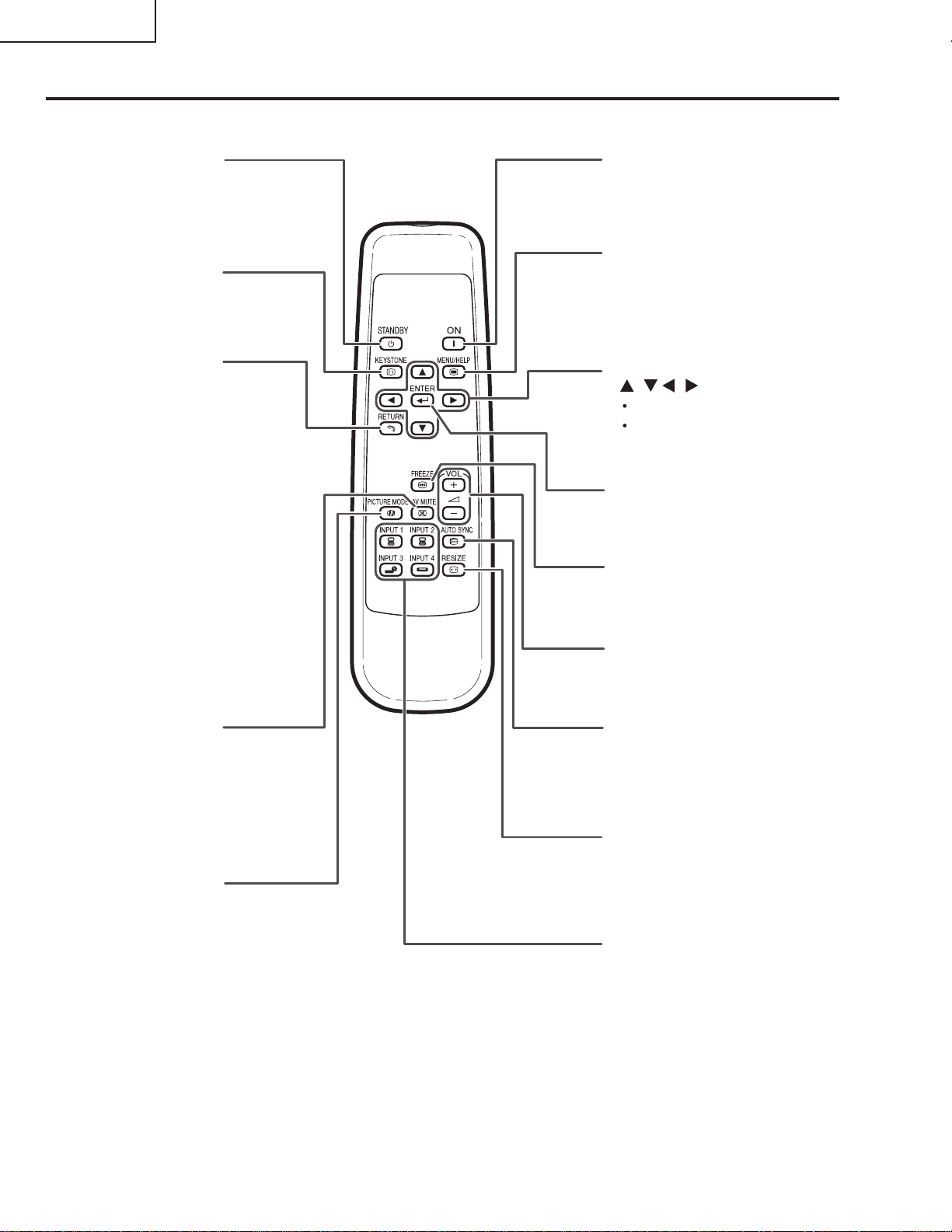
STANDBY button
For putting the
projector into the
standby mode.
KEYSTONE button
For entering the
Keystone Correction
mode.
RETURN button
For returning to the
previous menu screen
during menu operations.
ON button
For turning the power on.
MENU/HELP button
For displaying adjustment
and setting screens, and
help screen.
Adjustment buttons
(///)
For selecting menu items.
For adjusting the Keystone
Correction when in the
Keystone Correction mode.
ENTER button
For setting items selected
or adjusted on the menu.
FREEZE button
For freezing images.
AV MUTE button
For temporarily
displaying the black
screen and turning
off the sound.
PICTURE MODE
button
For selecting the
appropriate picture.
Volume buttons
For adjusting the
speaker sound level.
AUTO SYNC button
For automatically adjusting
images when connected
to a computer.
RESIZE button
For switching the screen
size (STRETCH, SIDE
BAR, CINEMA ZOOM).
INPUT 1, 2, 3 and 4
buttons
For switching to the
respective input modes.
12
Page 13
DT-100
13
Page 14
DT-100
14
Page 15
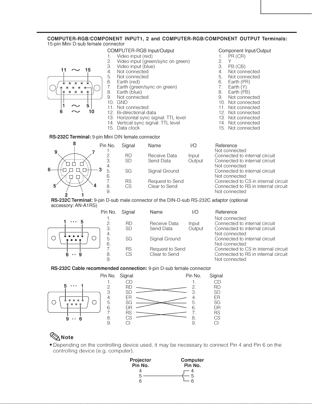
Connection Pin Assignments
DT-100
15
Page 16
DT-100
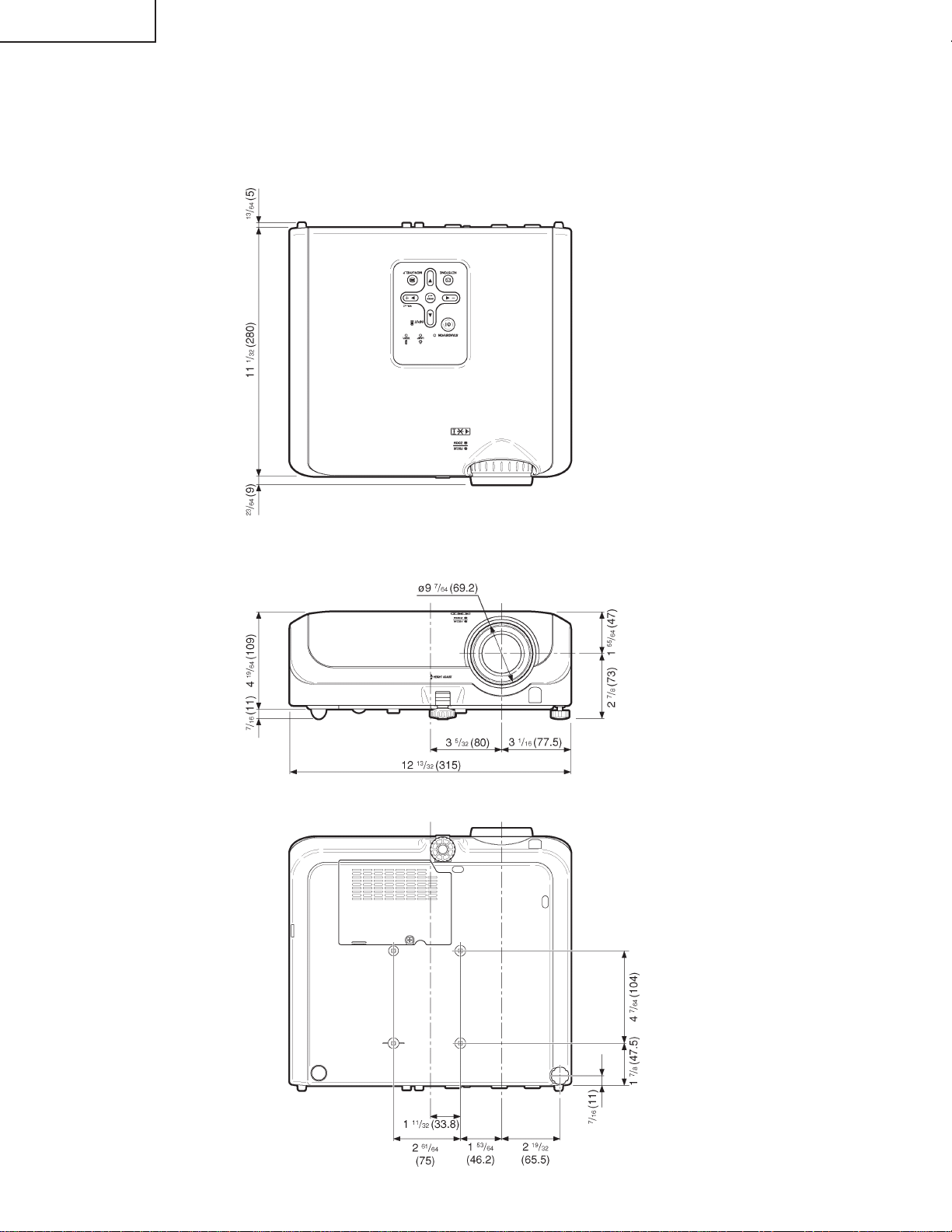
DIMENSIONS
Units: inches(mm)
16
Page 17
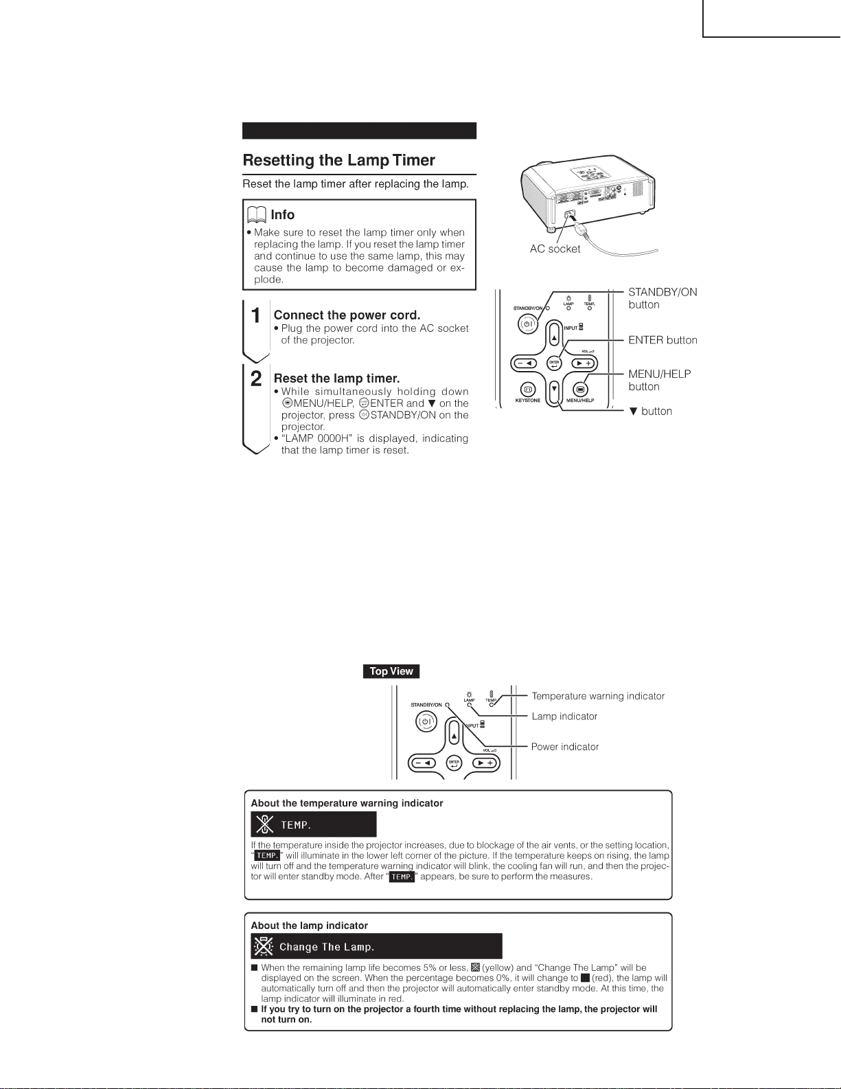
RESETTING THE T OT AL LAMP TIMER
● Resetting the total lamp timer
When replacing the lamp, reset the total lamp timer in the procedure below.
DT-100
Lamp
■ It is recommended that the lamp (sold separately) be replaced when the remaining lamp life becomes 5% or less,
or when you notice a significant deterioration in the picture and color quality. The lamp life (percentage) can be
checked with the on-screen display.
■ Purchase a replacement lamp of type AN-100LP from y our place of purchase, nearest Sharp A uthorized Projector
Dealer or Service Center.
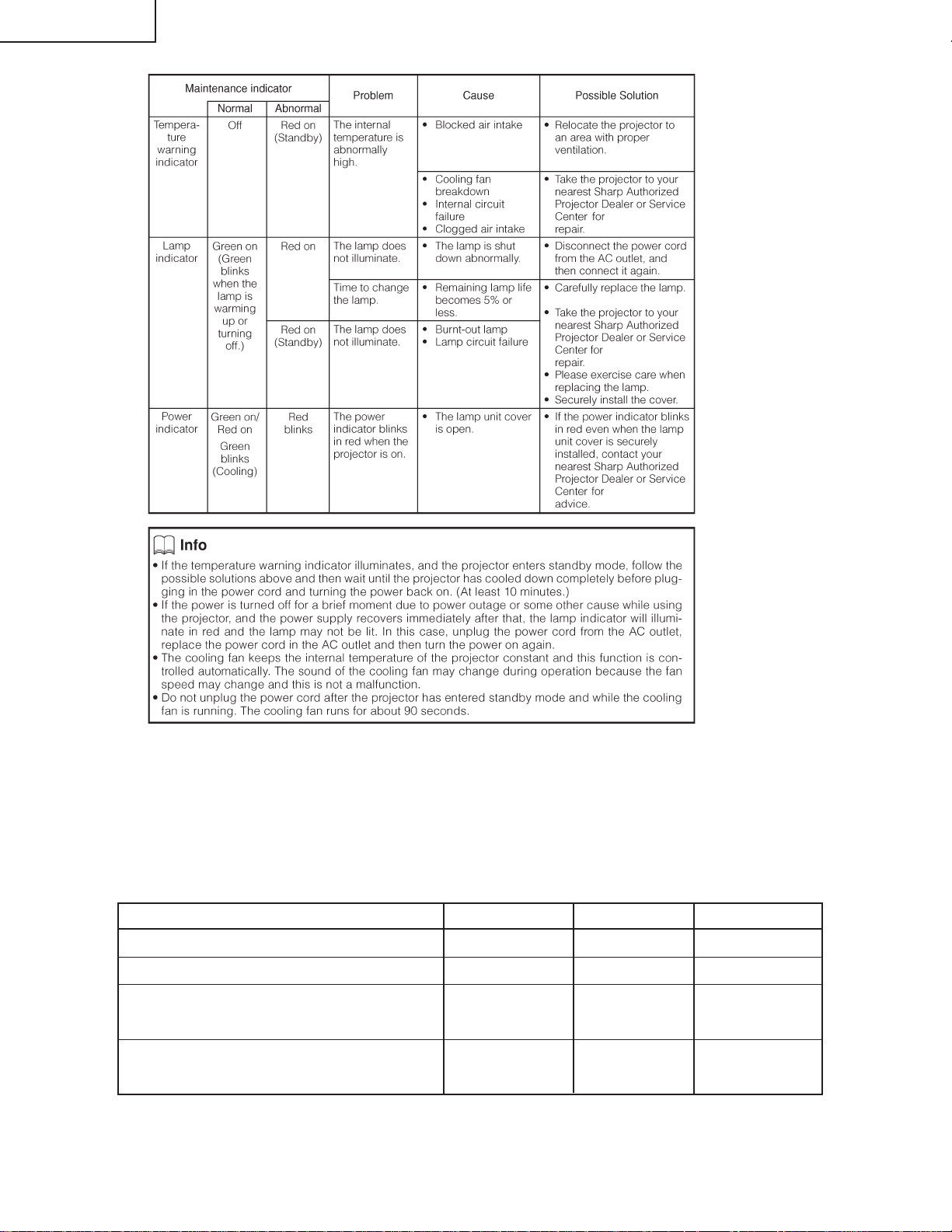
■ The warning lights (power indicator, lamp indicator and temperature warning indicator) on the projector indicate
problems inside the projector.
■ If a problem occurs, either the temperature warning indicator or the lamp indicator will illuminate red, and the
projector will enter standby mode. After the projector has entered standby mode, follow the procedures given
below.
17
Page 18
DT-100
■Keystone correction range expansion and vertical compression adjustment function
The variable range of the keystone can be expanded to over the user adjustable range by using
the following RS-232C commands. In addition, the vertical compression can be adjusted.
Command description
Control Command Parameter Return
Disabling function BKLM _0 OKorERR
Enabling function BKLM _1 OKorERR
Keystone correction range expansion BKST **** OKorERR
(-200 - +200)
Vertical compression adjustment BKVO **** OKorERR
(-300 - +300)
18
Page 19
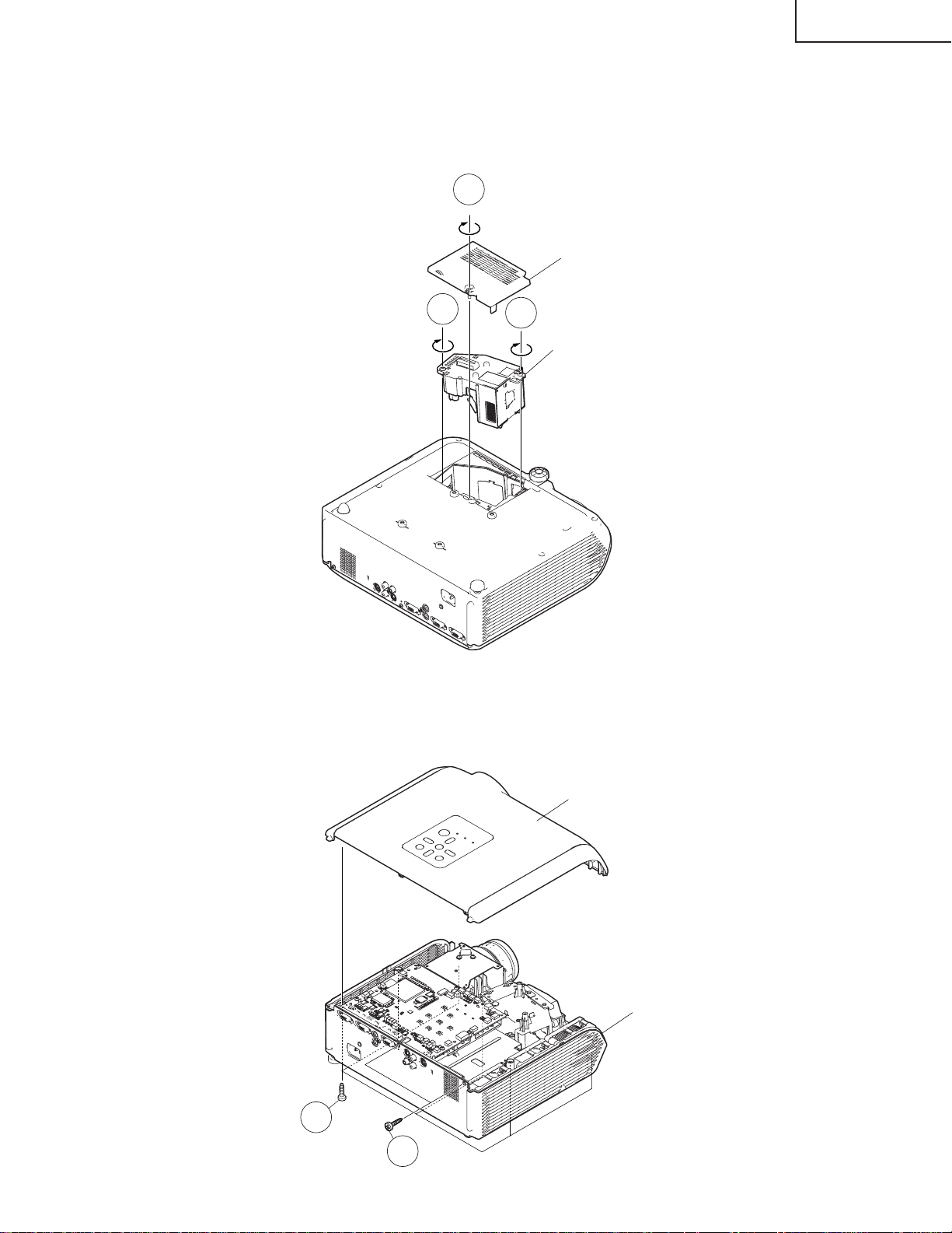
REMOVING OF MAJOR PARTS
1.Removing the lamp door and the lamp unit
1-1. Loosen the lamp door fixing screw. Lift off the lamp door.
1-2. Remove 2 lamp unit fixing screws to detach the lamp unit.
1-1
DT-100
Lamp Door
1-2
2.Removing the top body
2-1. Remove 8 top body fixing screws to detach the Top body.
1-2
Lamp Unit
2-1
Top Body
Bottom Body
2-1
19
Page 20
DT-100
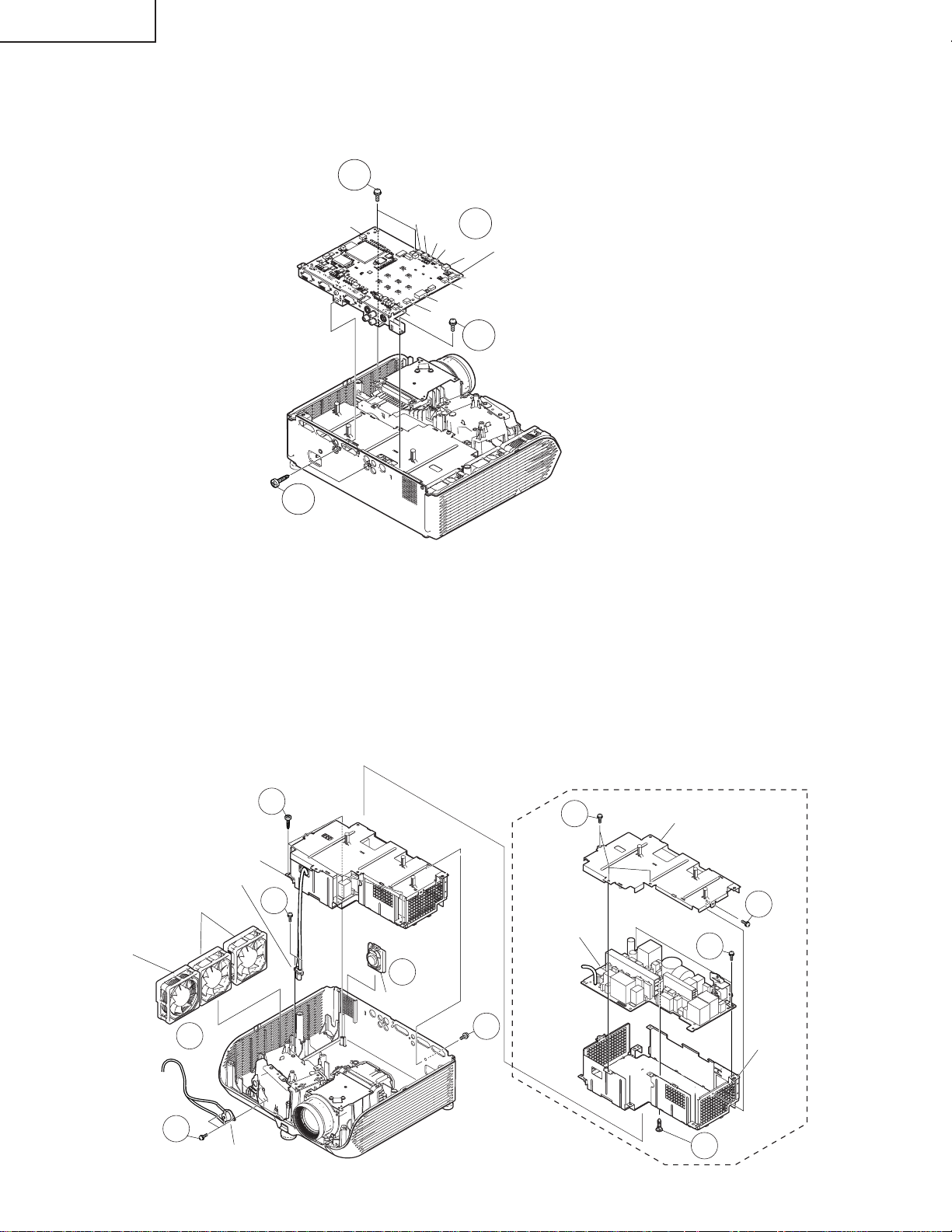
3.Removing the main PWB unit
3-1. Remove all connectors from the main PWB unit.
3-2. Remove 2 terminal fixing screws.
3-3. Remove 3 main PWB fixing screws to detach the main PWB unit.
3-3
[RC]
[CW]
[SO]
[FA]
[MO]
[FB]
[EA]
[LF]
3-1
[BB]
MAIN PWB Unit
[FD]
[FC]
3-3
3-2
4.Removing the speaker, fan, and power supply ballast unit
4-1. Remove the speaker.
4-2. Remove 2 fans for the power supply ballast unit and 1 fan for the optical mechanism unit.
4-3. Remove 2 bimetal fixing screws to detach the bimetal.
4-4. Remove 2 lamp socket fixing screws to detach the lamp socket.
4-5. Remove 1 inlet fixing screw.
4-6. Remove 4 ballast unit fixing screws to detach the power supply ballast unit.
4-7. Remove 4 ballast shield (upper) fixing screws to detach the ballast shield (upper).
4-8. Remove 2 ballast PWB fixing screws and 1 clip to detach the power supply PWB unit from the ballast shield
(lower).
POWER SUPPLY BALLAST Unit
Lamp Socket
Fans for power supply
ballast unit
Fan for
optical
mechanism
unit
4-2
4-3
Bimetal
4-6
4-4
4-1
Speaker
20
POWER SUPPLY
BALLAST PWB
Unit
4-5
4-7
Ballast shield (upper)
4-7
4-8
Ballast
shield
(lower)
4-8
Page 21
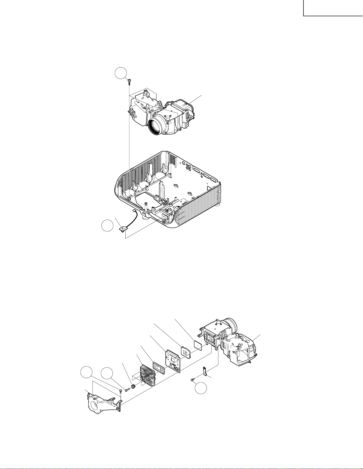
5.Removing the optical mechanism unit and RC light receiver PWB
5-1. Remove 4 optical mechanism unit fixing screws to detach the optical mechanism unit.
5-2. Remove the RC light receiver PWB unit.
5-1
Optical Mechanism Unit
DT-100
RC Light Receiver PWB
5-2
6.Removing the photosensor PWB unit, blower fan, DMD PWB, and DMD
6-1. Remove 1 photosensor PWB fixing screw to detach the photosensor PWB.
6-2. Remove 2 blower fan fixing screws to detach the blower fan.
6-3. Remove 4 DMD heatsink fixing screws to detach the DMD PWB unit and the DMD.
DMD
Optical Mechanism Unit
Photosensor PWB Unit
6-1
Blower fan
DMD spring
6-2
DMD socket
DMD PWB Unit
Backer plate
DMD heatsink
6-3
21
Page 22
DT-100
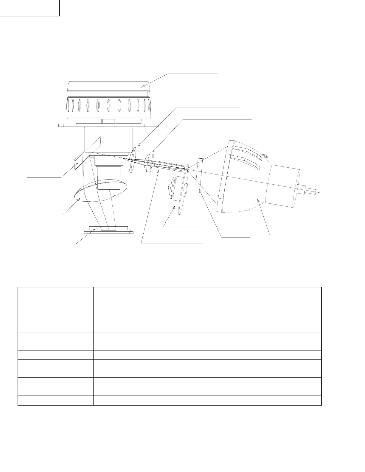
THE OPTICAL UNIT OUTLINE
Layout for proper setup of the optical components and parts (top view)
(Schematic diagram)
Projection lens
Illumination lens 2
Illumination lens 1
Reflection
mirror
Plastic Lens
Color wheel
DMD
Item Function
Lamp Light source. DC high-pressure mercury lamp.
UV/IR cut filter (UV GLASS)
Color wheel Splits light from the light source into R, G, B and W through a color filter.
Rod (ROD INTEGRATOR) Assures uniform light ray.
Illumination lens Focus light from the rod on DMD.
(ILLUMINATION LENS 1, 2)
Reflection mirror Reflects light from the illumination lenses toward DMD.
Condencer Lens Condenses the light from the reflection mirror to the DMD and the pupil of the
(PLASTIC LENS)
DMD Turns the internal micromirror ON/OFF at the rate of color component of each dot
Projection lens Enlarges light from DMD and projects it on a screen.
Filters out harmful UV and IR rays from the lamp.
projection lens.
of the input source to reflect light.
Rod Integrator
UV Glass
Lamp
22
Page 23
DT-100
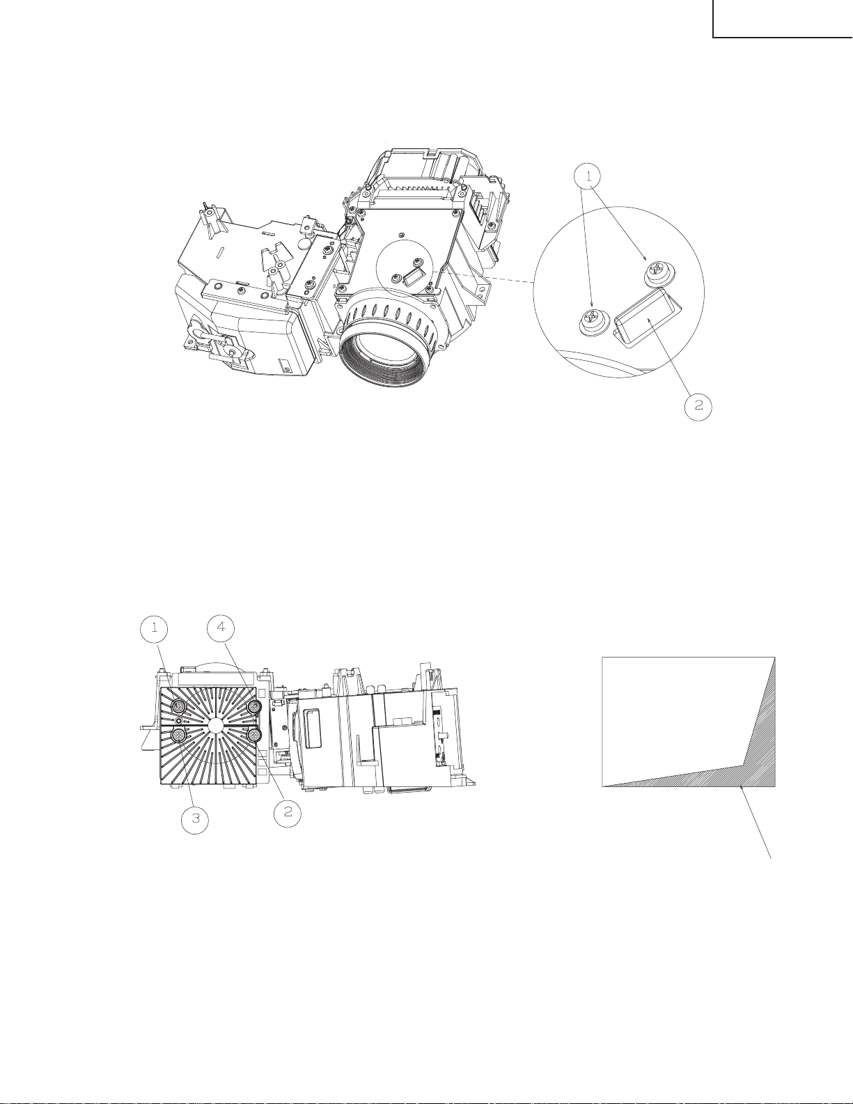
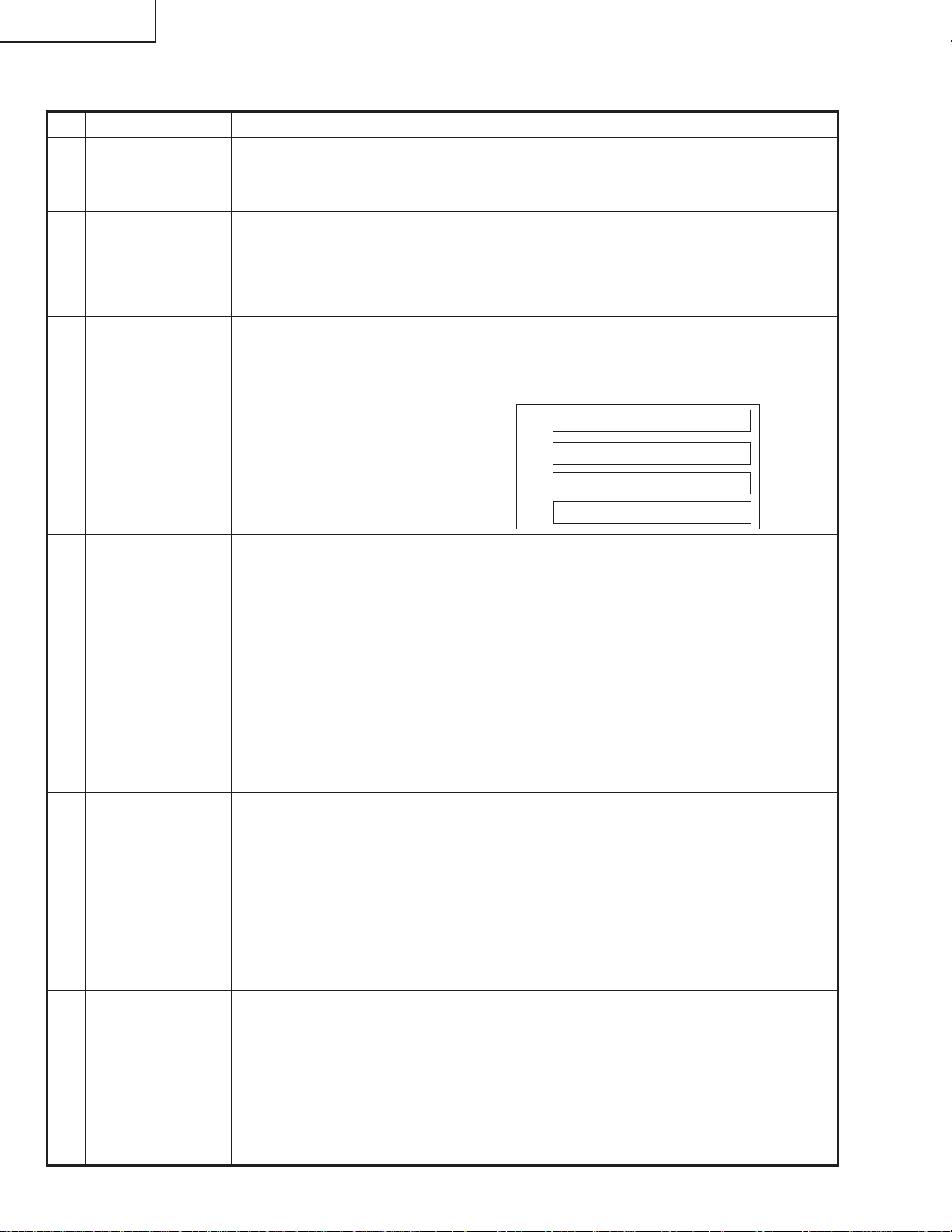
If shading shown in Figure 1 appears on the screen after replacing DMD, turn the adjustment screw of the optical
engine to adjust the lighting area of DMD.
1. Loosen the adjustment lever fixing screw 1. After adjusting the lighting area with the adjustment lever 2, tighten
the adjustment lever fixing screw 1.
Tightening order: 1→2→3→4
Screw torque: 0.44 ± 0.05 N·m
When mounting DMD, tighten the 4 screws evenly.
Fig. 1
Shading
23
Page 24
DT-100
ELECTRICAL ADJUSTMENT
No. Adjusting point Adjusting conditions Adjusting procedure
1 EEPROM
initialization
2 Model setting (Process menu)
3 Adjustment of
CW index
4 R/G/B contrast
adjustment
(manual or
automatic)
1. T urn on the power (with the
lamp on) and warm up the
set for 15 minutes.
1. Select the following group
and subject.
Group: CONFIRM
Subject: MODEL
1. Signal input: Send 256
STEP color bar.
XGA series (XGA60HZ),
SVGA series (SVGA60HZ)
2. Select the following group
and subject.
Group: ADJUST
CW/Auto KS
Subject: CW-INDEX.
1. Select the following group
and subjects.
Group : ADJUST
AD/DLP
Subject : R-CONT
G-CONT
B-CONT
(Process GAMMA interlock)
2. Feed white signal with the
amplitude level of 96%
(0.67Vpp). XGA series
(XGA60HZ), SVGA series
(SVGA60HZ)
» Make the following settings.
Press S2551 to call the process mode and execute
"SS2" on SS menu.
1. Set as below.
: 1 (default)
1. Feed the signal to input 1.
2. Select the adjustment item and adjust the lamp
gradation patterns of RGBW so that smooth
patterns without noise appear.
W
R
G
B
1. Measure chromaticity of the 96% white wind pattern
using CA100.
2. On the screen where bit dropouts occur, raise the
values of R/G/B-Contrast. Adjust the values so that
bright red, green, and blue bit dropouts appear on a
black background; and amounts of change in x value
of R and y values of G/B become 100/1000 or more.
3. If adjustment is performed manually watching the
screen, make adjustment so that bright red, green,
and blue bit dropouts appear on more than half of
the screen.
5 RGB white
balance adjustment
6 sRGB white
balance adjustment
1. Feed the 50% gray signal.
XGA series (XGA60HZ),
SVGA series (SVGA60HZ)
2. Select the following group
and subjects.
Group : ADJUST
AD/DLP
Subject : R-GAIN
G-GAIN
B-GAIN
1. Feed the 50% gray signal.
XGA series (XGA60HZ),
SVGA series (SVGA60HZ)
2. Select the following group
and subjects.
Group : CONFIRM/DLP
Subject : S-G-OS
S-B-OS
1. Raise the values of two of R/G/B-GAIN (default:
100) so that the following chromaticity values are
obtained using CL200.
x value: 300 ± 5
y value: 320 ± 5
1. Adjust S-G-OS and S-B-OS so that the following
chromaticity values are obtained using CL200.
x value: 313 ± 5
y value: 329 ± 5
24
Page 25

Check items
No. Adjusting point Adjusting conditions Adjusting procedure
DT-100
1 Adjustment of
RGB brightness
2 Adjustment of
Component
offset
3 Adjustment of
DLP Brightness
1. Select the following group
and subjects.
Group : CONFIRM/AD
Subject : R-BRIGHT
G-BRIGHT
B-BRIGHT
(Process GAMMA interlock)
1. Feed 10-step signal with
480P component 100%
amplitude.
2. Select the following group
and subjects.
Group : CONFIRM/AD
Subject :C-R-OS
C-B-OS
(Process GAMMA interlock)
1. Select the following group
and subject.
Group : CONFIRM/DLP
Subject :R-BLK
G-BLK
B-BLK
(Process GAMMA interlock)
1. Check the fixed value.
Fixed value : 127
1. Check the fixed value.
C-R-OS : 260
C-B-OS : 260
1. Check the fixed value.
Fixed value : 256
4 Video Contrast
adjustment
5 Adjustment of
Video Brightness
1. Feed NTSC 100% wind
pattern signal. (Signal with
burst)
2. Select the following group
and subjects.
Group : CONIRM/
VIDEO
Subject : V-CONT
1. Feed NTSC 100% wind pattern signal. (Signal with
burst)
2. Select the following group
and subject.
Group : CONFIRM/VIDEO
Subject : V-BRIGHT
1. Check the fixed value.
Fixed value : 124
1. Check the fixed value.
Fixed value : 68
25
Page 26
DT-100
No. Adjusting point Adjusting conditions Adjusting procedure
6 Adjustment of
Video Tint
7 Adjustment of
Video color
saturation
8 RGB tone
reproduction
adjustment
9 VIDEO white
balance adjustment
1. Feed split color bar.
2. Select the following group
and subject.
Group : CONFIRM/VIDEO
Subject : V-HUE
1. Select the following group
and subject.
Group : CONFIRM/VIDEO
Subject : V-COLOR
1. Feed the SMPTE pattern
signal.
1. Feed the 50% gray signal.
2. Select the following group
and subjects.
Group :CONFIRM/VIDEO
Subject : V-R-OS
V-B-OS
1. Check the fixed value.
Fixed value : 128
1. Check the fixed value.
Fixed value : 154
1. Make sure the 100% and 95% white as well as the
0% and 5% black gradations are visible.
1. V-R-OS is 132.
V-B-OS is 132.
10 White balance
checking and
readjustment
11 Off-timer per-
formance
performance
checking
13 Auto sync
performance
checking
14 Monitor out
check
1. RGB Inputt
sRGB Input
VIDEO Input
DTV Input
DVD Input
1. Select the following group
and subjects.
Group :CONFIRM/CHECK
Subject : TEMP-OFF
1. Heat the thermistor with a
hair dryer.
1. Feed the phase check pattern signal.
1. Send signals to INPUT 1
and INPUT 2.
2. Connect another monitor to
the monitor out.
3. Connect the audio OUT.
Check that there is no deviation of white balance with
the monitor.
1. Select OFF from the process mode.
Make sure the off-timer starts with 5 minutes
onscreen and count one minute in one second.
And then indication is 0 minute, the power supply
of the set is cut off.
1. Make sure that the temperature is indicated.12 Thermistor
1. In the VGA, SVGA, XGA and SXGA modes, make
sure the Clock, Phase, H-Pos and V-Pos settings
can be automatically adjusted.
1. Check that the same images as seen on the screen
appear on the connected monitor and that the sound
from the sound source connected to the audio OUT
is heard.
26
Page 27
No. Adjusting point Adjusting conditions Adjusting procedure
DT-100
15 RS232C opera-
tion check
16 Model name and
version check
17 Delivery set-
tings
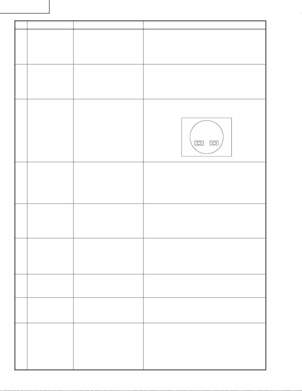
* Writing a software program (before main PWB is mounted)
Use the DLP Composer Lite Ver. 4.2 or higher to download the firmware.
After writing the specified version of firmware to the PWB using the RS232C cable, check the version of the written
firmware.
If no software program is written, all three LEDs light up in the chassis inspection process.
1. Connect the unit and a PC
with the RS232C cable.
1. Select the following group.
Group : INFO/VERSION.
1. Send a command from the PC, and check it functions correctly.
1. The model name appears in the MODEL field, and
the firmware version in the VERSION field. Check
that they are correct.
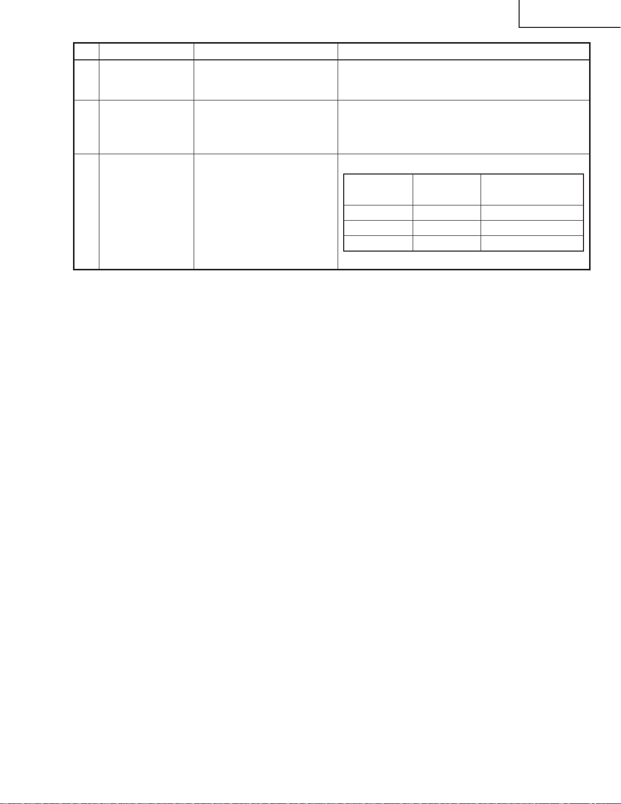
1. Make the following settings.
Destination Process Remote control
adjustment adjustment
USA SS4 Factory setting at 4
China SS6 Factory setting at 6
Others SS3 Factory setting at 3
1. Calling and quitting the process mode with the control keys on this model.
∗ Although it is possible for the process OUT to exit using the process menu, the IN/OUT toggle command is also
available considering the existing specification.
1-1. Calling and quitting
With the menu not displayed, press the "ENTER", "ENTER", "VOL+", "VOL-", "ENTER", "ENTER" and "MENU"
keys on the remote control (one for C50/45 or P25/20 system is also usable) or on the main unit.
1-2. Others
Press the S2551 process key (toggle) on the main PWB to call and quit the process menu.
Note: When adjusting in the process mode, set a signal with a vertical frequency of 60 Hz or no signal. (May not be
properly adjusted with other signals.)
2. Resetting the lamp timer for this model
2-1. Resetting procedure
In Stand-by, run this command to clear the operating time of the lamp to 0 and turn on the power.
Press and hold """, "ENTER", and "MENU", and then press the "STANDBY/ON" key of the set.
3. Forced disabling of the System-Lock of this model
3-1. Disabling procedure
With System-Lock input window onscreen, press the "MENU", "ENTER", "ENTER", "MENU", "ENTER", "ENTER"
and "MENU" keys, in this order, on the remote controller.
27
Page 28
DT-100
» Adjustment mode process menu
1st Layer 2nd Layer Default
ADJUST CW/Auto KS CW-INDEX 20
CAL
K-SENS (0)
AD/DLP R-CONT 110
G-CONT 110
B-CONT 110
R-GAIN 100
G-GAIN 100
B-GAIN 100
SS SS1 −
SS2 −
SS3 −
SS4 −
SS5 −
SS6 −
CONFIRM AD R-BRIGHT 127
G-BRIGHT 127
B-BRIGHT 127
C-R-OS 260
C-B-OS 260
DLP R-BLK 256
G-BLK 256
1st Layer 2nd Layer Default
INFO VERSION MODEL −
VER. −
PATTERN RGB 1
RGB50 1
CORSS 1
STEP 1
COLOR 1
CHR 1
LAMP CURRENT 0
HISTORY1 0
HISTORY2 0
HISTORY3 0
HISTORY4 0
TOTAL 0
TEMP/FAN TEMP1 −
TEMP2 −
FAN0 3
FAN1 3
FAN2 3
OTHER 232C
EXIT
232C-MODE
0
B-BLK 256
S-R-OS 128
S-G-OS 128
S-B-OS 128
VIDEO V-CONT 124
V-BRIGHT 68
V-COLOR 154
V-HUE 128
V-R-OS 132
V-G-OS 128
V-B-OS 132
OFFSET-MODE
OFFSET-CONT
OFFSET-BRI
MODEL
CHECK LED-CHK 0
MODEL-SELECT
TEMP-OFF −
0
0
0
1
28
Page 29
RefNo.
1
R905
2
--
3
IC7707
4
IC7704
5
IC7701
1
2
Adjustmentjig(resistanceload25Ω)
Partname
Partname
Partcode
Partcode
PWMcontroller
RR-FZA002WJZZ
DUNTKD148WEF0
RH-iXB458WJZZ
Manufacturer
RUNTZA018WJZZ
AsahiCommunication
SMK
VHITA78L05F-1Y
VHIM51995AF-1Y
Cementresistor
ControlPWB
Ballastmicroprocessor
5Vregulator
BallastUnit
LampCable
(QCNW-D573WJQZ)
AdjustmentJig
(RUNTZA018WJZZ)
ConnectingCord
(Q C NW -E007WJZZ)
Projector
TP1
TP2
−
+
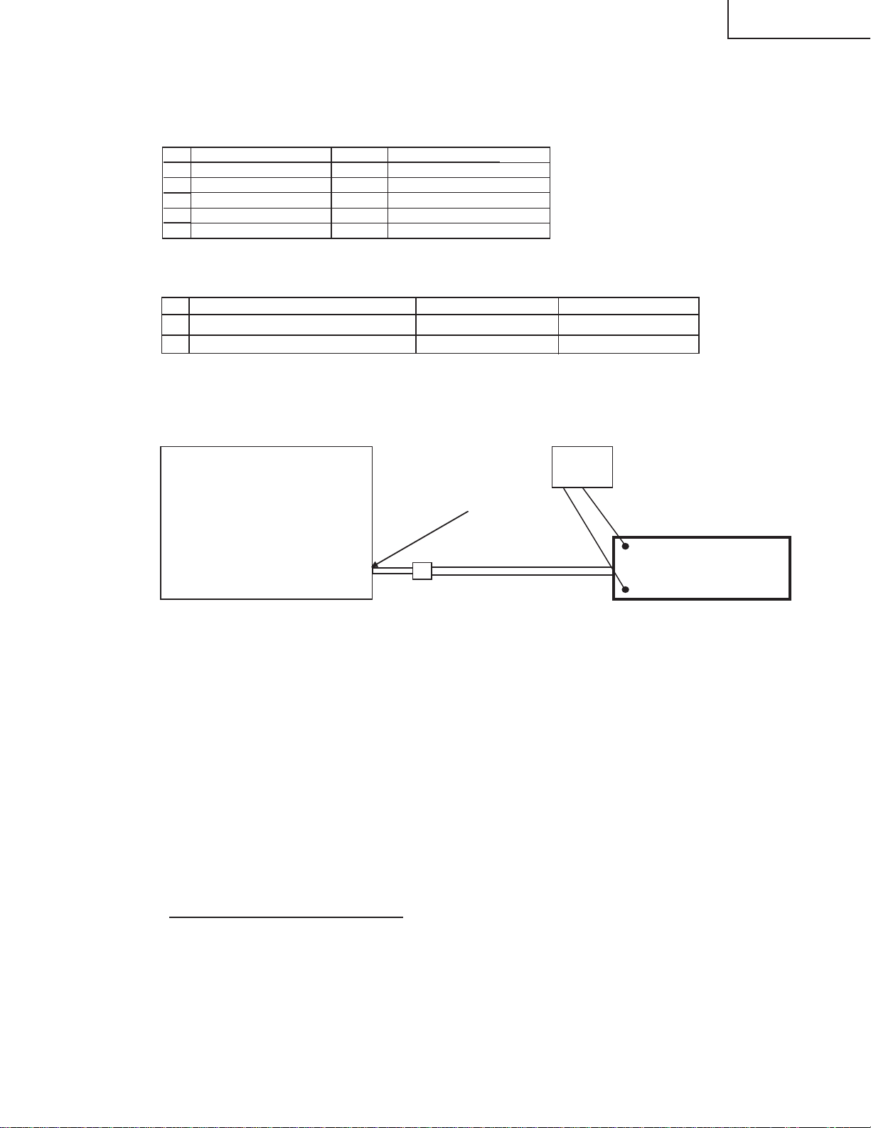
[Adjustmentofballastunitoutputpower(lamppower)]
1.Listofpartsrequiringadjustment
Whenreplacingthefollowingparts,adjusttheballastunitoutputpower(lamppower).
2.Adjustmentjigs
Thefollowingjigsarerequiredforadjustingtheballastunitoutputpower(lamppower).
3.Ballastunitoutputpower(lamppower)adjustmentmethod
Adjusttheballastunitoutputpower(lamppower)inthefollowingmethod.
[Adjustmentmethod]
(1)Unplugtheballastunitlampcable(QCNW-D573WJQZ)oftheprojectorfrom
thelampandconnectthecabletotheconnectingcord(QCNW-E007WJZZ).
(2)Connecttheconnectingcord(QCNW-E007WJZZ)totheadjustmentjig
(RUNTZA018WJZZ).
(3)ConnectTP1oftheadjustmentjig(RUNTZA018WJZZ)tothenegativeterminalofthe
testerandTP2tothepositiveterminal.
(4)Turnontheprojector.
(5)Agetheprojectorfor60secondsormore.
(6)Adjustthevolumeresistor(R7728)oftheballastcontrolPWB(DUNTKD148WEF0)so
thatthevoltageofthetesterreaches83±0.5V.
Adjustmentvalue:83±0.5V
[Cautions]
(1)Cautionforelectricshock:DonottouchthetestpointsTP1andTP2oftheadjustment
jigwhensupplyingpowersinceahighvoltageandlargecurrentisappliedtothem.
(2)Cautionforheat:Becarefulthattheresistanceloadoftheadjustmentjigproducesahigh
temperaturewhensupplyingpower.
(3)Connectionofthelampcable:Checkthatthelampcableandconnectingcord(QCNW-E
007WJZZ)areconnectedsecurely.
Poorconnectionmaycausesmokingorignitionduetoarcdischarge.
[Settingmethod]
Tester
(Voltage)
DT-100
29
Page 30
DT-100
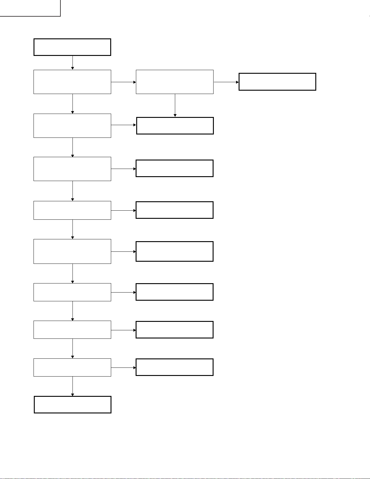
TROUBLE SHOOTING TABLE
Checking the basic
operation
Does the power LED light
up or flash in red or green?
YES
Does the set function with
its keys or the remote
controller?
YES
Lamp does not turn on or it
turns off in a short time.
NO
Nothing is displayed or
white vertical line noise
NO
Colors are not displayed
normally. Color deviation
and color fluctuation occur.
NO
NO
NO
YES
YES
YES
Has P1701 come off or is it
loose?
NO
Go to "Main PWB check".
Go to "Checking the lamp
light-up".
Go to "DMD system
check".
Check PHOTO SENSOR
circuit.
YES
Fully insert the connector.
Are RGB and component
input displayed normally?
YES
Is VIDEO input displayed
normally?
YES
Is S-VIDEO input
displayed normally?
YES
END
NO
NO
NO
Go to "RGB and
component signal check".
Go to "VIDEO input
check".
Go to "S-VIDEO input
check".
30
Page 31

YES
NO
Is 6 V applied to TL1702
and 13 V to TL1703?
Is approx. 6 V applied to
TL1742?
YES
Is 1.5 V applied to
TL1741?
Go to "Power supply
ballast PWB check".
NO
Check IC1742 and
peripheral circuits.
NO
Check IC1741 and
peripheral circuits.
YES
Is 3.3 V applied to
TL1762?
NO
Check IC1763 and
peripheral circuits.
Is 2.5 V applied to
TL1763?
NO
Check IC1762 and
peripheral circuits.
YES
Is 5 V applied to TL1791?
NO
Check IC1791 and
peripheral circuits.
YES
Is 3.3 V applied to
TL1792?
NO
Check IC1792 and
peripheral circuits.
YES
Is 12 V applied to
TL1761?
NO
Check IC1761 and
peripheral circuits.
YES
Main PWB check
YES
Is 3.3 V applied to pin(1)
of IC1743?
NO
Check IC1743 and
peripheral circuits.
YES
Is 3.18 V applied to pin(1)
of IC2001?
NO
Check IC2001 and
peripheral circuits.
YES
Is 3.3 V applied to pin(3)
of S2001?
NO
Check that it is set to the N
side. Or remove S2001.
YES
Is rectangular wave of 50
MHz sent to X2251 pin(3)?
NO
YES
Check IC2002, IC2262,
IC2263 and peripheral
circuits.
Check X2251 and
peripheral circuits.
DT-100
31
Page 32

DT-100
DMD system check
Check P2501 for breakage
and solder crack and
peripheral resistance for
solder crack.
Check SC9101 for
breakage and solder crack.
Is there any vertical stripe
(block noise) on the
NO
Is the screen all black?
YES
Is 3.27 V applied to IC2231
pin(1) and 1.8 V to TL2231?
YES
Is 400 MHz on IC2241 pin
(20)?
YES
Is approx. 7 V applied to
TL9303?
YES
NO
YES
NO
NO
NO
Check IC2231, IC2201,
and their peripheral
circuits.
Check IC2241 and
peripheral circuits.
The main PWB and DMD
PWB are in poor contact.
Check the contact surface
for dirt and smear.
Check the DMD connector
for breakage.
Reassemble the DMD,
optical mechanism, and
DMD PWB.
Is approx. 26 V applied to
TL9301?
YES
Is approx. -26 V applied to
TL9302?
YES
NO
NO
Check IC9301 and
peripheral circuits.
32
Page 33

Power supply PWB
check
DT-100
Is 6 V applied to pins (7)
and (8) of the connector
P704?
YES
Is 13 V applied to pins (3)
and (4) of the connector
P704?
YES
Does the lamp turn on?
YES
Check the main PWB.
Are connectors P704 and
CN901 fully inserted?
NO
NO
NO
NO
1
Check peripheral circuits of
IC703.
Securely insert the
connectors.
YES
Is DC voltage of 380 V
applied to both ends of
C704?
YES
Is R766 in the OPEN
status?
YES
Check circuits R766 and
after or replace R766.
NO
NO
Is pin (11) of the connector
P704 at "H"?
YES
Check peripheral circuits
of IC902.
Is LAMP-EN/SYNC signal
properly sent to pin (14) of
the connector P704?
(Refer to the waveform
chart 1.)
YES
Are GATE waveforms of
Q901 and Q903
appropriate?
(See waveform diagram
8.)
NO
NO
NO
Check the main PWB.
Check the main PWB.
Check the ballast PWB.
33
Page 34

DT-100
1
Are connectorsP701 and
P702 fully inserted?
YES
Is AC voltage between 100
− 240 V applied to both
ends of C707?
YES
Is the bimetal broken?
(Connection between 1 and
2 of P702)
YES
Is R717 open?
YES
Check that P704 connector
pin (11) is at "H". Replace
R717.
NO
NO
NO
NO
Securely insert the connectors.
Replace F701.
Press the red button on the
bimetal.
Is R705 open?
YES
Replace F705.
Check that the power
supply FAN FB and FC
are not stopped.
NO
Check peripheral circuits of
IC703.
34
Page 35

NO
Go to "Check when the
lamp turns off soon after
turning on".
YES
Securely insert the
connectors.
YES
Securely insert the
connectors.
YES
Check IC3581 and
peripheral circuits. (Refer
to the waveform chart 2.)
NO
Check IC1701 and
peripheral circuits. (Refer
to the waveform chart 1.)
NO
Fully insert the connectors
or replace the harnesses.
YES
Replace the lamp.
YES
Go to "Power supply PWB
check".
NO
Replace both D911 and
D912.
YES
Replace D914 or D910,
whichever is short-circuited.
YES
Replace the color wheel.
YES
Checking the lamp
light-up
Does the lamp turn on
when the power is turned
Is the lamp tight in the
socket?
NO
Has the FPC cable to
SC3581 come off or is it
loose?
Is rotating sound of the
color wheel heard?
NO
Is approx. 0.7 V applied to
TL1706?
YES
NO
Has the harness connected
to P702 on the power
supply unit come off, or is it
loose? Otherwise, is it
broken?
NO
Dose the lamp turn on after
the replacement?
YES
Is 340 VDC applied to both
ends of C914?
NO
Is D911 or D912 shortcircuited?
Is D914or D910 shortcircuited?
YES
DT-100
35
Page 36

DT-100
Check when the lamp turns
off soon after turning on
Have connectors P1703,
P1721, P1722, P1723 and
P1724 come off or are they
loose?
NO
Is each cooling fan
rotating?
YES
Is approx. 3 V applied to
TL1721?
YES
Is 12 V applied to TL1761?
YES
Is 2.5 V applied to
TL1763?
YES
YES
NO
NO
NO
NO
Securely insert the
connectors.
Check the cooling fan.
Check peripheral circuits of
Q1721.
Check IC1761, IC3581 and
peripheral circuits.
Is 3.3 V applied to TL1762?
NO
YES
Go to "DMD system check".
Check IC1762 and
peripheral circuits.
Is 5 V applied to TL1791?
YES
Is 5 V applied to TL1712?
YES
Is the signal of 180 Hz
sent to TL1716?(When
vertical frequency of the
input signal is 60 Hz)
YES
Is the signal of 180 Hz
sent to TL1706? (When
vertical frequency of the
input signal is 60 Hz)
YES
NO
NO
NO
NO
Check IC1763 and
peripheral circuits.
Check IC1791 and
peripheral circuits.
Is 5 V applied to TL1712
with P1703 removed?
YES
Check PHOTO SENSOR
PWB.
Check IC1701 and
peripheral circuits.
NO
Check connection of
FB1710.
Check the power supply
ballast PWB.
36
Page 37

YES
End
YES
Check IC3002 and the
peripheral circuits (check
IC3052 for INPUT 2).
NO
Check IC1792 and
peripheral circuits.
NO
Check IC1763 and
peripheral circuits.
NO
RGB and component
signal check
Send component signal or
RGB signal of 1080i (or
720P) from INPUT 1 or
INPUT 2. Select INPUT 1
or INPUT 2 using keys on
the main unit or the remote
control.
Is image displayed
normally?
Are picture signals sent to
TL3201, TL3204, and
TL3205?
NO
YES
Is 3.3V applied to TL1792?
Is 3.3V applied to TL1762?
YES
Check IC3201 and
peripheral circuits.
YES
DT-100
37
Page 38

DT-100
S-VIDEO (INPUT 3)
check
Send S-Video signal (color
signal) from INPUT 3.
Select INPUT 3 using keys
on the main unit or the
remote control.
Is image displayed
normally?
NO
Is image displayed in black
and white?
NO
Is S-VIDEO signal (Y) sent
to R3306?
YES
YES
YES
NO
VIDEO (INPUT 4) check
Send VIDEO signal from
INPUT 4. Use buttons on
the main unit or the remote
control to select INPUT 4.
End
Check S-VIDEO terminal
and peripheral circuits of
Q3311.
Check S-VIDEO terminal
and peripheral circuits of
Q3301.
Is 1.8 V applied to
TL3358?
YES
Is 3.3 V applied to
TL1792?
YES
Is 1.5 V applied to
TL1762?
YES
NO
NO
NO
End
Check VIDEO terminal and
peripheral circuits of
Q3321.
Check IC3352 and
peripheral circuits.
Check IC1792 and
peripheral circuits.
Check IC1763 and
peripheral circuits.
YES
Is image displayed
normally?
NO
Is VIDEO signal sent to
C3326?
NO
YES
Check IC3351 and
peripheral circuits.
38
Page 39

- M E M O -
DT-100
39
Page 40

DT-100
BLOCK DIAGRAM
H
G
F
E
D
C
B
A
87109654321
40
Page 41

DT-100
41
1716 1918151413121110
Page 42

DT-100
U
O VERALL WIRING DIAGRAM
H
G
F
D
E
D
C
B
RH-HXA015WJPZ
P3502
B+3.3VA
TEMP1-AD
A
POWER
87109654321
42
Page 43

DUNTKD139FMF7
DT-100
43
PHOTO
1716 1918151413121110
Page 44

DT-100
DESCRIPTION OF SCHEMATIC DIAGRAM
VOLTAGE MEASUREMENT CONDITION:
1. Voltages at test points are measured at the
supply voltage of AC 220V. Signals are f ed by a color
bar signal generator for servicing purpose and the
above voltages are measured with a 20k ohm/V tester.
WAVEFORM MEASUREMENT CONDITION:
1. Waveforms at test points are observed at the supply
voltage of AC 220V. Signals are fed by a color bar
signal generator for servicing purpose.
INDICATION OF RESISTOR & CAPACITOR:
RESISTOR
1. The unit of resistance “Ω” is omitted.
(K=kΩ=1000 Ω, M=MΩ).
2. All resistors are ± 5%, unless otherwise noted.
(J= ± 5%, F= ± 1%, D= ± 0.5%)
3. All resistors are 1/10W, unless otherwise noted.
4. All resistors are Carbon type, unless otherwise noted.
C : Solid
S : Oxide Film T : Special
N : Metal Coating
CAPACITOR
1. All capacitors are µF, unless otherwise noted.
(P=pF=µµF).
2. All capacitors are 50V, unless otherwise noted.
3. All capacitors are Ceramic type, unless otherwise
noted.
(ML): Mylar (TA): Tantalum
(PF): Polypro Film (ST): Styrol
W
: Cement
CAUTION:
This circuit diagram is original one, therefore there may be a
slight difference from yours.
SAFETY NOTES:
1.DISCONNECT THE AC PLUG FROM THE AC
OUTLET BEFORE REPLACING PARTS.
2.SEMICONDUCTOR HEAT SINKS SHOULD BE
REGARDED AS POTENTIAL SHOCK HAZARDS
WHEN THE CHASSIS IS OPERATING.
IMPORTANT SAFETY NOTICE:
PARTS MARKED WITH “å” ( ) ARE
IMPORTANT FOR MAINTAINING THE SAFETY OF
THE SET. BE SURE TO REPLACE THESE PARTS
WITH SPECIFIED ONES FOR MAINTAINING THE
SAFETY AND PERFORMANCE OF THE SET.
44
Page 45

WAVEFORMS
DT-100
45
1716 1918151413121110
Page 46

DT-100
SCHEMATIC DIA GRAM
Ë
H
G
F
MAIN UNIT-1/8
iXB589WJ
E
D
iXB589WJ
C
B
A
87109654321
46
Page 47

DT-100
47
1716 1918151413121110
Page 48

DT-100
Ë
H
G
F
MAIN UNIT-2/8
E
D
C
B
A
87109654321
48
Page 49

DT-100
49
1716 1918151413121110
Page 50

DT-100
Ë
H
G
F
MAIN UNIT-3/8
E
D
C
B
A
87109654321
50
Page 51

DT-100
51
1716 1918151413121110
Page 52

DT-100
Ë
H
G
F
MAIN UNIT-4/8
E
D
C
B
A
87109654321
52
Page 53

DT-100
53
1716 1918151413121110
Page 54

DT-100
Ë
H
G
F
MAIN UNIT-5/8
E
D
C
B
A
87109654321
54
Page 55

DT-100
55
1716 1918151413121110
Page 56

DT-100
Ë
H
G
F
MAIN UNIT-6/8
E
D
C
B
A
87109654321
56
Page 57

DT-100
57
1716 1918151413121110
Page 58

DT-100
Ë
H
G
F
MAIN UNIT-7/8
E
D
C
B
A
87109654321
58
Page 59

DT-100
59
1716 1918151413121110
Page 60

DT-100
Ë
H
G
F
MAIN UNIT-8/8
E
D
C
B
A
87109654321
60
Page 61

DT-100
61
1716 1918151413121110
Page 62

DT-100
Ë
H
G
F
DMD UNIT-1/3
E
D
C
B
A
87109654321
62
Page 63

DT-100
63
1716 1918151413121110
Page 64

DT-100
Ë
H
G
F
DMD UNIT-2/3
E
D
C
B
A
87109654321
64
Page 65

DT-100
65
1716 1918151413121110
Page 66

DT-100
Ë
H
G
F
DMD UNIT-3/3
E
D
C
B
A
87109654321
66
Page 67

DT-100
67
1716 1918151413121110
Page 68

DT-100
Ë
H
G
F
BALLAST POWER UNIT
E
D
C
B
A
87109654321
68
Page 69

DT-100
69
1716 1918151413121110
Page 70

DT-100
Ë
H
G
F
BALLAST CONTROL UNIT
E
D
C
B
A
87109654321
70
Page 71

DT-100
458
1716 1918151413121110
71
Page 72

DT-100
Ë
H
G
F
PHOTOSENSOR UNIT
E
D
C
B
A
654321
72
Page 73

DT-100
Ë
R/C UNIT
H
G
F
E
D
C
B
A
654321
73
Page 74

DT-100
PRINTED WIRING BOARD ASSEMBLIES
H
G
F
E
D
C
B
A
MAIN Unit (Side-A)
87109654321
74
Page 75

DT-100
75
1716 1918151413121110
Page 76

DT-100
R3224
R3225
FB3521FB3522
D3051
R3051
D3056
R3052
D3057
R3053
R3054
R3055
R3056
R3057
R3058
R3059
IC3051
IC3052
FB3351
FB3352
FB3353
FB3354
FB3355
D3065
C1726
D3066
D3067
R1704
R3069
R1706
R3070 R3071
R3072
R3073
R3074
FB2201
P2532
P2533
R2503 R2504
R2505
R2506
R2507
R2508
R2509
Q2531
P3301
R2510
R2511
R2512
R2513
R2514
R2515
R2516
R2517
R2518
R2521
R2522
R2523
C3103
R2524
R2525
R1779
R2527
R2528
R2529
FB2241
D2531
D2532
R2532
R2533
R2534
R2535
FB3001
FB3002
FB3003
C3511
FB3201
C3512
FB3202
R3102
C3513
FB3203
R3103
C3514
FB3204
IC3102
R2553R2554
C3521
C3522
C3523
C3524
R3511
C3151
R3512
C3152
C3153
C3154
S2551
C3354
C3355
R3521R3522
FB3051
C3362
FB3052
C3363
FB3053
C3364
FB3054
C3365
FB3055
FB3056
FB3057
C3369
R3151 R3152
C3370
C3371
R3155
C3372
R3156
R3157
R3158
IC3152
FB1708
R3355
FB1709
R3356
R3359
FB1710
FB1711
FL3102
FL3103
R3360
C2001
C2002
C2003
R3365
R3366
C2203
C2204
C2205 C2206
C2207 C2208
C2209
C2210
C2211
C2212
C2213
C2214
C2215
C2216
C2217
C2218
C2219
C2028
R2001
R2002
C2220
R2004
C2221
R2005
C2222
C2223
C2031
IC2001
IC2002
R2202R2203
R2204
R2205
R2206
R2207 R2208 R2209
IC2201
R2019
R2210 R2211 R2212
R2213
R2214
C2241
S2001
C2242
C2245
C2246
C2248
C2250
C2251
C2252C2253
C3001
C3201
C2262
C3202
C3203
C3204
FB2531
FB2532
C3206
C3207
C3208
R2241
C3209
R2244
C3210
IC2241
C3211
C3212
C3215
C3216
C3217
C3218
C3219
D3001
SC2531
R3001
D3006
FB3102
R3002
D3007
FB3103
R3003
C3220
R3004
C3221
R3005
C3222
R3006
C3223
R3007
R3009
IC3001
IC3002
C3227
R3201
R3202
R3203
R3010
R3204
R3205
D3015
R3206
D3016
D3017
R3209
IC3201
IC2263
R3211
R3212
R3213
P1703
R3020
R3214
P1704
R3021
R3215
R3022
R3216
R3023
R3217
R3024
R3218
R3025
R3219
C3051
FB3511 FB3512
R3220
C3055
R3221
R3222
C3056
C3057
R3223
H
G
F
E
D
C
B
A
MAIN Unit (Chip Parts Side-A)
76
87109654321
Page 77

DT-100
3
5
C3514
5
3
3
1
1
1
1
1
1
1
1
1
2
2
2
P3562
FB3566
C3572
FB3565
L1723
L1727
FB1729
C1724
FB1728
D1725
Q1724
R1727
R1728
FB1732
C1725
Q1725
FB1731
D1726
FB1730
D2571D2572D2573
FB1727
D1731
D1732 D1733
R1701
C1701
D1701
P1723P1724
P1722
P3561
R1702
C1703
Q1701
R3589
R3592
R3593
P1702
R1708
S2555
S2556
S2554
FB1707
R1707
R1705
P1705
C1705
S2557
S2558S2559
P1703
FB1710
FB1711
R1704
R1706
C1726
P2533
2528
2529
2
1
0
9
8
7
6
5
4
3
2
1
365
353
352
66
3355
372
D1730
S2553
P1721
FB1723
S2552
FB1722
FB1721
FB3582
C3591
FB3583
R3591
SC3581
FB3584 FB3585
R3588
C3586 C3588
R3304
Q3301
R3302
C3323
R3325
L3321L3322
C3322
C3301
R3303
FB3301
D3301
R3301
R3324
FB3321
R3321
FB3311
D3321
R3322
R3311
R3323
C3321
C3502
FB3501
R3502
C3504
C3506
R3501
C3501
C3503
D3552
D3553
FB3502
D2561 D2562
R2564
FB2562
FB3552
FB3551
FB2561
D2563
D2564
P3551
R2563
R3326
C3326
C3324
C3325 Q3321
C3304
C3305
C3306
L3302
C3302
C3303
R3306
C3104
R3305
L3301
R3101
D3104D3105
FB3101
FL3101
D3102
D3101
FB3105
D3103
FB3104
IC3101
C3103
12
12
512
R3103
FB3103
FL3103
R3102
FB3102
FL3102
1716 1918151413121110
77
Page 78

DT-100
H
G
F
E
D
C
B
A
MAIN Unit (Side-B)
87109654321
78
Page 79

DT-100
79
1716 1918151413121110
Page 80

DT-100
2
0
IC1764
Q3512
R3515
3
3
H
G
F
E
D
C
B
FB1726
FB1725
C1723
D1724
L1726
FB1724
R1730
Q1723
L1722
L1728
R1710
FB1703
FB1704
FB1705
FB1706
FB1701
FB1702
FB2563
R2566
R2565
R2567
R1731
C1727
C2561
C2563
C2562
C1721
R1711
R1703
R1712
IC2561
R3578
TH3561
C1728
C3567
R3572
R3573
C3568
IC3551
R3556
R2568
C2564
L1724
C3565
C3554
C2565
C3571
R3577
R3558
R3560
R1732
FB3563
C3570
R3506
Q3501
D3501
R3504
IC1701
C3557
R3552
R3503
S3561
R3559
R3551
R1726
R1764
R1765
C3566
FB3564
R3557
C3555
R3554
R3555
C3553
D3502
R3507
Q3502
R3505
R1761
R1769
C1764
C3564
R3571
R3576
C3569
C1702
R1709
R1713
D3551
IC3552
R1725
D1722
D1721
C1762
R2571
C3556
C3552
C1763
Q2571
R2575
R2576
Q1721
R1723
R1724
C1760
R3570
C3563
R3553
R3541
L3311
R3312
C3311
R1722
R1721
D1761
IC1761
R3544
C3312
R3315
Q2572
R2577
R2578
R3579
R3580
C3313
Q3311
C1761
IC3562
C3541
C3540
R3543
R3567
R3606
L3312
D3311
C3595
Q3537
R3542
C3314
R3314
R3313
Q3535
C3535
Q2573
R2579
R2580
R2020
C3315
R3597
R3596
R3595
R3594
C3562
FB3562
R3538
R3535
C3596
Q2574 Q2575
R2582
R2581
C3561
FB3561
R3566
R1792
C1794
IC1791
R3539
R3533
Q3534
C3537
C3533
R3536
C3532
R3564
C3538
IC3533
D1702
C3593
C3530
R1791
C1792
R3598
R3540
C1704
R2584
R2583
IC3561
R3563
D1791
R3599
Q3536
C3590
R2572
R3562
C3536
C3594
C3592
C3589
C3534
R3545
R3531
R3546
R3532
R3537
D3581 D3582 D3583
R3590
C3587
FB3581
C1781
R1777
R3561
C1793
C1791
C3526
C3528
R3534
R3601
C3544
C3545
C3539
C3531
IC3531
IC3581
C1778
C1779
R1748
FB1761
R1749
R3526
R3530
R3529
R3602
C3601
C3585
R1776
IC1743
C1753
C3527
C3529
C3584
R1775
R1774
C1774
Q3524
R3518
Q3601
R3603
R3109
D3584
R1750
R3527
C3583
C1776
C1755
C1754
FB1741
R3568
R3565
R3574
C3525
C3582
C1775
IC1763
Q3522
R3548
R3547
R3549
R3550
Q3523
R3525
R3520
R3604 R3605
R1772
C1756
C1748
C1771
C1773
C1772
D1764
L1761
IC1742
C1749
R3575
Q3521
R3528
C3602
IC3601
C3101
C1722
C1777
C1770
R1771
R1768
R1770
R1747
R1773
R1780
R1781
C1780
C1752
R1745
C1746
R1795
D1723
C1747
D1762
C1765
C1767
C1769
C1751
R1717
R1794
R1746
IC1741
C1766
C1745
R1744
D1742
R3372
R1714
IC1792
C1797
R1793
C1798
L1721
IC1762
D1765
C1744
C3102
L1741
Q1703
Q1722
D1763
R1743
R1741
R1742
C1750
R1716
C1796
R1729
C1768
D1741
C1741
C1742
C1743
R3371
R2232
R2231
C1729
Q1702
C1795
C2231
C2232
C2233
R2234
R2235
IC1721
C3367
R1718
R3369
Q3331
C1711 C171
R1715
C3515
C3505
C
D3331
IC3
R3370
D17
R
D3512
A
MAIN Unit (Chip Parts Side-B)
87109654321
80
Page 81

Q1722
D1763
R1743
R1741
R1742
C1750
R1716
C1796
R1729
C1768
D1741
C1741
C1742
C1743
R3371
R2232
R2231
C1729
Q1702
C1795
IC1721
C1711
R1718
C3515
C2231
C3367
Q3331
R1715
C2232
C2233
R2234
R2235
C3505
R3369
D3331
R3370
C1712
D1703
D3512
C3368
IC3352
IC1764
Q3512
R3515
R2233
IC2231
R3513
D2231
R3352
R3516R3517
Q3511
R3514
C1710
D3511
R2242
R2243
C3366
C3357
X3351
C3356
D3521
R3523
C2247
R2245
R2246
D3522
R2248
R2247
R3362 R3363
C3359 C3360 C3361
IC3351
C3351
C3352
R3524
R2017
C2015
R2013
C3353
C2004
R2252
D3054
C2255
R2531
FB2002
R3361
C3358
D3053
P2501
FB2251
C2254
X2251
R3354
R3351
C3213
R3107
R3110
D3052
R3353
R2520
C2256
IC2251
L2005
R2519
C2035
R2015
R2008
R2012
L2004
R3587
R3358
R3357
C3008
R2009
R2014
R3582
C2033 C2034
R2010
R2007
C2027
C2023
C2022
C2017
R2201
C2201
C2202
C2012
C2008
R3367
R3368
R3153
Q3101
R3108
R3034
D3055
R3033
R2018
C3226
FB3207
R3154
C3007
C2029
C3225
R3026R3027
C2016
C2018
FB3206
R3029
R3036
R3065
R3028
R3030
C3224
D3060
R3064
C3054
R3035
R3037
C2030
R2016
C2026
C2013
C2010
C2005
FB2001
R3210
R3068
Q3102
Q3103
C2025
C2014
R2003
C2007
D3059
R3063
R3062
C3053
R3031 R3032
C3009
R3038 R3039
R3067
IC3003
C2032
C2020
C2019
R2526
R3569
C2009
R3041 R3042
D3058
R3060
R3061
C3052
D3002
D3003
D3004
D3005
R3581
R3586
C2557
C3010
R3066
C2006
C2021
C2011
C3581
R2006
C2553
C2555
R2551 R2552
IC3004
R3044
R3040
D3010
R3015
R3016
C3004
FB3005
FB3007
FB3004
R3008
FB3006
C2551
C3205
C3214
R3043
R3019
R3584
R3585
C2558
C2556
R3208
R3207
R3014
R2561
R3583
C2554
D3009
R3013
C3003
C2552
C1785
R3018
R2501R2502
R2562
R1778
C1784
C1783
C3006
C3005
R3012
R2261
C1782
D3008
R3011
C3002
C2501
IC2261
R2263
R3017
IC2262
C2261
DT-100
C2264
C2263
FB2261
81
1716 1918151413121110
Page 82

DT-100
H
G
F
E
DMD Unit (Side-A)
TH9102
R9102
C9102
C9101
R9103
D
C9318
C9315
R9305
C9314
C
B
C9316
C9311
C9309
C9301 C9302
C9306
D9302
D9301
R9301
C9307
IC9301
C9304
R9302
L9301
L9302
FB9301
R9303
C9313
FB9302
C9303
C9312
C9310
R9304
D9303
C9317
C9507
C9505
C9511
C9508
FB9303
C9503
C9510
C9502
C9504
C9509
C9506
C9513
C9512
SC9101
C9308
C9305
A
C9514
DMD Unit (Chip Parts Side-A)
C9501
654321
82
Page 83

DT-100
H
G
F
E
D
C
B
DMD Unit (Side-B)
A
654321
83
Page 84

DT-100
H
G
F
E
D
C
B
A
BALLAST POWER Unit (Side-A)
87109654321
84
Page 85

DT-100
85
1716 1918151413121110
Page 86

DT-100
H
G
F
E
D
C
B
A
BALLAST POWER Unit (Side-B)
87109654321
86
Page 87

DT-100
87
1716 1918151413121110
Page 88

DT-100
FB705
FB706
R702
R703 R704 R705
R706
R707
R708
R710
R711
R712
R715
R718
R721
R917
R725
R728
R730 R731
R732
C702
C703
C705
C706
C708
C903
C713
C716
C717
R762
R763 R764
C92
C923
D702
D704
D705
D706 D707
D719 D720
D722
IC902
H
G
F
E
D
C
B
A
BALLAST POWER Unit (Chip Parts Side-B)
87109654321
88
Page 89

R708
R707
R706
D710
D708
C701
R735
C723
C724
R736
C722
R733
C718
Q705
C739
R738
R737
D713
R743
Q706
C719
C729
R742
R740
R749
R748
R752
R753
FB701
FB702
R754
C736
DT-100
FB704
FB704
R760
R759
R757R758
R756
R755
R751
IC704
R750
C921
R918
903
R917
C923
C922
D915
R913
FB904
D906
R945
R946
R914
Q904
R907
R909
R944
R943
C904
C924
R901
FB903
R911
C905
R912
R902 R903
R921
R924
C909
R923
R920
C910
R908
D909
C912
R904
R935
C913
R932
R931
R930
C925
R934
C918
R933
R929
R925
R939
R928
R927
R926
Q906
R936
R940
C919
R947
Q907
R942
R941
R938
C902
R948
R949
R950
89
1716 1918151413121110
Page 90

DT-100
H
G
F
BALLAST CONTROL Unit (Side-A)
E
C7752
R7726
R7704
C7701
R7708
R7724R7725
C7709
C7713
R7721
C7718
C7719
R7731
C7717
R7712
IC7701
C7707
R7717
C7744
C7745
X7701
C7727
P7701
IC7707
C7734
C7736
C7733
D7712
R7761
R7787
C7746
C7741
C7742
C7728
R7793
C7739
C7737
R7772
R7775 R7776
R7770
R7769
D7711
Q7707
R7762
C7710
C7715
D7703
R7720
R7723
R7719
C7712
C7731
IC7709
R7755
D7715
D
D7714
D7713
C
B
BALLAST CONTROL Unit (Chip Parts Side-A)
A
654321
90
Page 91

DT-100
H
G
F
BALLAST CONTROL Unit (Side-B)
E
C7722
C7720
D7704
C7738
D7705
R7788
R7715
Q7711
Q7708
R7767
R7777
Q7709
R7765
C7740
R7773
R7763
R7792
C7743
C7721
R7771
R7791
R7774
R7778
R7764
R7789
R7790
R7794
R7796
R7760
R7743
R7795
C7730
R7786
R7757
R7758
R7709
R7702 R7703
C7702
R7705
R7710
D
C7705
C7704
R7753
R7711
R7752
R7707
C7703
R7730
C
R7706
R7713
R7718
C7711
R7732
R7727
C7716
R7766
R7734
Q7701C7706
Q7704
D7701
C7735
Q7702
R7701
R7733
R7728
Q7703
R7729
R7722
R7739
D7702
R7716
Q7705
C7708
R7714
R7735
Q7706
R7736
IC7704
R7759
R7756
R7785
R7751
R7749
R7750
R7754
R7748
R7744
R7745
R7747
R7746
D7706
R7737
R7741
R7742
R7740
C7724
R7781
IC7705
C7723
R7779
C7725
C7726
R7738
C7751
C7750
R7780
C7749
R7783R7784
B
BALLAST CONTROL Unit (Chip Parts Side-B)
A
654321
91
Page 92

DT-100
H
G
F
PHOTOSENSOR Unit (Side-A)
E
D
C
B
P1101
PHOTOSENSOR Unit (Side-B)
R1110
IC1101
R1109
C1102
R1108
R1107
R1102
R1103
R1106
R1104
R1111
R1101
C1101
PHOTOSENSOR Unit (Chip Parts Side-B)
A
654321
92
Page 93

DT-100
H
G
F
E
D
C
R/C Unit (Side-A)
B
A
R/C Unit (Side-B)
654321
93
Page 94

DT-100
Ref. No. Part No. ★ Description Code Ref. No. Part No. ★ Description Code
Ref. No. Part No. ★ Description Code
PARTS LIST
PARTS REPLACEMENT
Parts marked with "å" are important for maintaining the safety of
the set. Be sure to replace these parts with specified ones for maintaining the safety and performance of the set.
HOW TO ORDER REPLACEMENT PARTS
To have your order filled promptly and correctly, please furnish the
following informations.
1. MODEL NUMBER 2. REF. NO.
3. PART NO. 4. DESCRIPTION
5. CODE 6. QUANTITY
in USA: Contact your nearest SHARP Parts Distributor.
For location of SHARP Parts Distributor,
Please call Toll-Free; 1-800-BE-SHARP
in CANADA: Contact SHARP Electronics of Canada Limited
Phone (416) 890-2100.
★ MARK: SPARE PARTS-DELIVERY SECTION
Ref. No. Part No. ★ Description Code
PRINTED WIRING BOARD ASSEMBLIES
DUNTKD139FMF7 J MAIN Unit CL
DUNTKD140WEF0 J DMD Unit BT
DUNTKD141WEF0 – PHOTOSENSOR Unit —
DSETUD147FMF9 J BALLAST POWER Ass’y CA
DUNTKD147WEF1 – BALLAST POWER Unit —
(Order the BALLAST POWER Ass’y (DSETUD147FMF9)
when replacing the ballast power unit.)
DUNTKD148WEF0 J BALLAST CONTROL Unit BE
DUNTKD164WEF0 – R/C Unit —
IC1701 VHiAHCT08PH-1Y J 74AHCT08PW AE
IC1721 VHiLV4053AT-1Y J SN74LV4053APWR AE
IC1741 VHiMP1580HS-1Y J MP1580HS-LF-Z AL
IC1742 VHiBD5246G+-1Y J BD5246G-TR AE
IC1743 VHiBD5246G+-1Y J BD5246G-TR AE
IC1761 VHiPQ120DNA-1Y J PQ120DNA1ZPH AG
IC1762 VHiPQ070XN1-1Y J PQ070XN01ZPH AG
IC1763 VHiMP1580HS-1Y J MP1580HS-LF-Z AL
IC1791 VHiPQ1K503M-1Y J PQ1K503M2ZP AF
IC1792 VHiPQ033DZ1-1Y J PQ033DZ01ZP AE
IC2001 VHiBU4213G+-1Y J BU4213G-TR AD
IC2002 RH-iXA806WJN1Q J 2504504-0005 CB
IC2201 VHiK4R271F8-1Q J K4R271669F-TCS BG
IC2231 VHiPQ018EN5-1Y J PQ018EN5MZPH AG
IC2241 VHiW134MSQC-1Y J IC AP
IC2261 VHiBR24L32F-1Y J BR24L32F-WE2 AG
IC2262 RH-iXB594WJZZQ J iXB594WJ BE
IC2263 VHiCY62146V-1Y J IC BA
IC2561 VHiiSL83220-1Y J ISL83220ECVZ AQ
IC3001 RH-iXB589WJZZS J iXB589WJ AN
IC3002 VHiEL8302iU-1Y J EL8302IUZ AT
IC3003 VHi7SB3157P-1Y J NC7SB3157P6X AE
IC3004 VHi7SB3157P-1Y J NC7SB3157P6X AE
IC3051 RH-iXB589WJZZS J iXB589WJ AN
IC3052 VHiEL8302iU-1Y J EL8302IUZ AT
IC3101 VHiVHCT125A-1Y J TC74VHCT125AFT AE
IC3102 VHiSN2G32CT-1Y J SN74AHC2G32HDC AE
IC3152 VHiLCX157MT-1Y J 74LCX157MTCX AE
IC3201 VHiMST3583+-1Q J MST3583-LF-110 AZ
IC3351 VHiTVP5146P-1Q J TVP5146PFP BG
IC3352 VHiPQ1K183M-1Y J PQ1K183M2ZPH AF
IC3531 VHiLV4053AT-1Y J SN74LV4053APWR AE
IC3533 VHiBA3530FS-1Y J BA3530FS-E1 AM
IC3551 VHiDA7056AT-1Y J TDA7056AT/N2 AM
IC3552 VHiPQ200WNA-1Y J PQ200WNA1ZPH AG
IC3561 VHiMB8346BV-1Y J MB88346BPFV AN
IC3562 RH-iXA966WJZZY J PIC16LF819-I/S AZ
IC3581 VHiA8904SLB-1Y J A8904SLB BE
Q1721 VSDTA114EE/-1Y J DTA114EE AB
Q1722 VSMCH3405++-1Y J MCH3405 AD
Q1723 VSMCH3405++-1Y J MCH3405 AD
Q1724 VSMCH3405++-1Y J MCH3405 AD
Q1725 VSMCH3405++-1Y J MCH3405 AD
Q2531 VSNDS332P//-1Y J NDS332P AD
Q2571 VS2SA1530AR-1Y J 2SA1530AR AB
Q2572 VS2SA1530AR-1Y J 2SA1530AR AB
Q2573 VS2SA1530AR-1Y J 2SA1530AR AB
Q2574 VS2SA1530AR-1Y J 2SA1530AR AB
Q2575 VS2SA1530AR-1Y J 2SA1530AR AB
Q3101 VSDTC114EE/-1Y J DTC114EE AB
Q3102 VS2SC3928AR-1Y J 2SC3928AR AB
Q3103 VS2SC3928AR-1Y J 2SC3928AR AB
Q3301 VS2SC3928AR-1Y J 2SC3928AR AB
Q3311 VS2SC3928AR-1Y J 2SC3928AR AB
Q3321 VS2SC3928AR-1Y J 2SC3928AR AB
Q3501 VS2SC3928AR-1Y J 2SC3928AR AB
Q3502 VS2SC3928AR-1Y J 2SC3928AR AB
Q3511 VS2SC3928AR-1Y J 2SC3928AR AB
Q3512 VS2SC3928AR-1Y J 2SC3928AR AB
Q3521 VS2SC3928AR-1Y J 2SC3928AR AB
Q3524 VS2SC3928AR-1Y J 2SC3928AR AB
Q3534 VS2SA1530AR-1Y J 2SA1530AR AB
Q3535 VS2SC3928AR-1Y J 2SC3928AR AB
Q3536 VS2SC3928AR-1Y J 2SC3928AR AB
Q3601 VS2SC3928AR-1Y J 2SC3928AR AB
DUNTKD139FMF7
MAIN UNIT
INTEGRATED CIRCUITS
TRANSISTORS
94
Page 95

DT-100
Ref. No. Part No. ★ Description Code Ref. No. Part No. ★ Description Code
DUNTKD139FMF7
MAIN UNIT (Continued)
DIODES
D1721 VHDDAN202K/-1Y J DAN202K AB
D1722 VHDDAN202K/-1Y J DAN202K AB
D1723 VHDRB551V30-1Y J RB551V30 AC
D1724 VHDRB551V30-1Y J RB551V30 AC
D1725 VHDRB551V30-1Y J RB551V30 AC
D1726 VHDRB551V30-1Y J RB551V30 AC
D1730 VHDRB551V30-1Y J RB551V30 AC
D1731 VHDRB551V30-1Y J RB551V30 AC
D1732 VHDRB551V30-1Y J RB551V30 AC
D1733 VHDRB551V30-1Y J RB551V30 AC
D1741 RH-EX1224CEZZY J Zener Diode, 2V AB
D1742 VHDSFPA73//2EY J SFPA73 AD
D1761 VHDHSU119//-1Y J HSU119 AB
D1762 RH-EX1234CEZZY J Zener Diode, 3.6V AE
D1764 VHDSFPA73//2EY J SFPA73 AD
D1765 VHDHSU119//-1Y J HSU119 AB
D1791 VHDHSU119//-1Y J HSU119 AB
D2531 VHDMA3120WA-1Y J MA3120WA AD
D2532 VHDMA3120WA-1Y J MA3120WA AD
D2561 RH-EX1271CEZZY J Zener Diode, 12V AB
D2562 RH-EX1271CEZZY J Zener Diode, 12V AB
D2563 RH-EX1271CEZZY J Zener Diode, 12V AB
D2564 RH-EX1271CEZZY J Zener Diode, 12V AB
D2571 RH-PXA097WJZZY J KPH-1608EC AC
D2572 RH-PXA038WJZZY J Photo Diode AC
D2573 RH-PXA038WJZZY J Photo Diode AC
D3001 VHDHSU119//-1Y J HSU119 AB
D3002 RH-EX1247CEZZY J Zener Diode, 5.6V AB
D3003 RH-EX1247CEZZY J Zener Diode, 5.6V AB
D3005 RH-EX1247CEZZY J Zener Diode, 5.6V AB
D3006 RH-EX1247CEZZY J Zener Diode, 5.6V AB
D3007 VHDHSU119//-1Y J HSU119 AB
D3008 VHDKDS226//-1Y J KDS226 AB
D3009 VHDKDS226//-1Y J KDS226 AB
D3010 VHDKDS226//-1Y J KDS226 AB
D3015 VHDKDS226//-1Y J KDS226 AB
D3016 VHDKDS226//-1Y J KDS226 AB
D3017 VHDHSU119//-1Y J HSU119 AB
D3051 VHDHSU119//-1Y J HSU119 AB
D3052 RH-EX1247CEZZY J Zener Diode, 5.6V AB
D3053 RH-EX1247CEZZY J Zener Diode, 5.6V AB
D3055 RH-EX1247CEZZY J Zener Diode, 5.6V AB
D3056 RH-EX1247CEZZY J Zener Diode, 5.6V AB
D3058 VHDKDS226//-1Y J KDS226 AB
D3059 VHDKDS226//-1Y J KDS226 AB
D3060 VHDKDS226//-1Y J KDS226 AB
D3065 VHDKDS226//-1Y J KDS226 AB
D3066 VHDKDS226//-1Y J KDS226 AB
D3067 VHDHSU119//-1Y J HSU119 AB
D3101 RH-EX1247CEZZY J Zener Diode, 5.6V AB
D3102 VHDKDS226//-1Y J KDS226 AB
D3103 RH-EX1247CEZZY J Zener Diode, 5.6V AB
D3104 VHDKDS226//-1Y J KDS226 AB
D3105 VHDKDS226//-1Y J KDS226 AB
D3301 RH-EX1247CEZZY J Zener Diode, 5.6V AB
D3311 RH-EX1247CEZZY J Zener Diode, 5.6V AB
D3321 RH-EX1247CEZZY J Zener Diode, 5.6V AB
D3501 RH-EX1247CEZZY J Zener Diode, 5.6V AB
D3502 RH-EX1247CEZZY J Zener Diode, 5.6V AB
D3511 RH-EX1247CEZZY J Zener Diode, 5.6V AB
D3512 RH-EX1247CEZZY J Zener Diode, 5.6V AB
D3521 RH-EX1247CEZZY J Zener Diode, 5.6V AB
D3522 RH-EX1247CEZZY J Zener Diode, 5.6V AB
D3551 VHDHSU119//-1Y J HSU119 AB
D3552 RH-EX1265CEZZY J Zener Diode, 10V AB
D3553 RH-EX1265CEZZY J Zener Diode, 10V AB
D3581 VHDBAT54SWT-1Y J BAT54SWT AC
D3582 VHDBAT54SWT-1Y J BAT54SWT AC
D3583 VHDBAT54SWT-1Y J BAT54SWT AC
D3584 VHDBAT54SWT-1Y J BAT54SWT AC
X2251 RCRUAA033WJZZY J Packaged Circuit AQ
PACKAGED CIRCUITS
X3351 RCRSC0170TAZZY J Crystal AG
COILS
L1721 VPCUN330K1R4NY J Peaking 33µH AC
L1722 VPCUN150KR63NY J Peaking 15µH AC
L1723 VPCUN150KR63NY J Peaking 15µH AC
L1724 VPCUN150KR63NY J Peaking 15µH AC
L1726 VPCUN150KR63NY J Peaking 15µH AC
L1727 VPCUN150KR63NY J Peaking 15µH AC
L1728 VPCUN150KR63NY J Peaking 15µH AC
L1741 RCiLPA213WJZZY J Coil AG
L1761 RCiLPA214WJZZY J Coil AG
L2004 VPCUN2R2MR16NY J Peaking 2.2µH AC
L2005 VPCUN2R2MR16NY J Peaking 2.2µH AC
L3301 VPD9M1R0JR57NY J Peaking 1µH AB
L3302 VPD9M1R8JR84NY J Peaking 1.8µH AC
L3311 VPD9M1R0JR57NY J Peaking 1µH AB
L3312 VPD9M1R8JR84NY J Peaking 1.8µH AC
L3321 VPD9M1R0JR57NY J Peaking 1µH AB
L3322 VPD9M1R8JR84NY J Peaking 1.8µH AC
CAPACITORS
C1701 VCKYCY1EF104ZY J 0.1 25V Ceramic AA
C1702 VCKYCY1EF104ZY J 0.1 25V Ceramic AA
C1703 VCKYCY1EF104ZY J 0.1 25V Ceramic AA
C1704 VCEAPF1CW106MY J 10 16V Electrolytic AB
C1705 VCKYCY1EF104ZY J 0.1 25V Ceramic AA
C1721 VCEAPF1EW106MY J 10 25V Electrolytic AC
C1722 RC-KZA066WJZZY J 1 25V Ceramic AB
C1723 RC-KZA066WJZZY J 1 25V Ceramic AB
C1724 RC-KZA066WJZZY J 1 25V Ceramic AB
C1725 RC-KZA066WJZZY J 1 25V Ceramic AB
C1726 VCEAPF1EW106MY J 10 25V Electrolytic AC
C1727 VCEAPF1EW106MY J 10 25V Electrolytic AC
C1728 VCEAPF1EW106MY J 10 25V Electrolytic AC
C1729 VCKYCY1EF104ZY J 0.1 25V Ceramic AA
C1741 RC-KZA101WJZZY J 10 6.3V Ceramic AC
C1742 RC-KZA101WJZZY J 10 6.3V Ceramic AC
C1743 VCKYCY1AB105KY J 1 10V Ceramic AB
C1745 VCKYCY1HB332KY J 3300p 50V Ceramic AA
C1746 VCKYCY1HB103KY J 0.01 50V Ceramic AA
C1748 VCAAPD1AJ686MY J 68 10V Electrolytic AE
C1749 VCKYCY1EF104ZY J 0.1 25V Ceramic AA
C1750 RC-KZA041WJZZY J 10 10V Ceramic AC
C1751 VCKYCY1CB104KY J 0.1 16V Ceramic AB
C1752 VCKYCY1HB102KY J 1000p 50V Ceramic AA
C1753 RC-KZA041WJZZY J 10 10V Ceramic AC
C1754 VCKYCY1HB102KY J 1000p 50V Ceramic AA
C1755 VCKYCY1EF104ZY J 0.1 25V Ceramic AA
C1760 VCKYCY1EF104ZY J 0.1 25V Ceramic AA
C1761 VCEAPF1CW336MY J 33 16V Electrolytic AD
C1762 VCKYCY1EF104ZY J 0.1 25V Ceramic AA
C1763 VCEAPF1EW106MY J 10 25V Electrolytic AC
C1764 VCKYCY1CB104KY J 0.1 16V Ceramic AB
C1765 RC-KZA101WJZZY J 10 6.3V Ceramic AC
C1766 VCEAPF0JW226MY J 22 6.3V Electrolytic AB
C1767 RC-KZA101WJZZY J 10 6.3V Ceramic AC
C1768 VCKYCY1EF104ZY J 0.1 25V Ceramic AA
C1769 VCKYCY1AB105KY J 1 10V Ceramic AB
C1770 VCEASH0JN476MY J 47 6.3V Electrolytic AC
C1771 VCKYCY1EF104ZY J 0.1 25V Ceramic AA
C1773 VCKYCY1HB152KY J 1500p 50V Ceramic AA
C1774 VCKYCY1EF104ZY J 0.1 25V Ceramic AA
C1775 VCKYCY1CB104KY J 0.1 16V Ceramic AB
C1778 VCAAPD1AJ686MY J 68 10V Electrolytic AE
C1779 VCKYCY1EF104ZY J 0.1 25V Ceramic AA
C1780 RC-KZA041WJZZY J 10 10V Ceramic AC
C1781 RC-KZA041WJZZY J 10 10V Ceramic AC
C1782 VCCCCY1HH220JY J 22p 50V Ceramic AA
C1783 VCCCCY1HH220JY J 22p 50V Ceramic AA
C1784 VCCCCY1HH220JY J 22p 50V Ceramic AA
C1785 VCKYCY1EF104ZY J 0.1 25V Ceramic AA
C1791 VCEAPF1CW336MY J 33 16V Electrolytic AD
95
Page 96

DT-100
Ref. No. Part No. ★ Description Code Ref. No. Part No. ★ Description Code
DUNTKD139FMF7
MAIN UNIT (Continued)
C1792 VCKYCY1EF104ZY J 0.1 25V Ceramic AA
C1793 VCEAPF1CW336MY J 33 16V Electrolytic AD
C1794 VCKYCY1CB104KY J 0.1 16V Ceramic AB
C1795 VCEAPF1CW106MY J 10 16V Electrolytic AB
C1796 VCKYCY1EF104ZY J 0.1 25V Ceramic AA
C1797 VCKYCY1CB104KY J 0.1 16V Ceramic AB
C1798 VCEAPF1CW336MY J 33 16V Electrolytic AD
C2001 VCKYCY1EF104ZY J 0.1 25V Ceramic AA
C2002 VCKYCY1HB103KY J 0.01 50V Ceramic AA
C2003 VCKYCY1EF104ZY J 0.1 25V Ceramic AA
C2004 VCKYCY1EF104ZY J 0.1 25V Ceramic AA
C2006 VCKYCY1EF104ZY J 0.1 25V Ceramic AA
C2007 VCKYCY1EF104ZY J 0.1 25V Ceramic AA
C2009 VCKYCY1EF104ZY J 0.1 25V Ceramic AA
C2010 VCKYCY1EF104ZY J 0.1 25V Ceramic AA
C2012 VCKYCY1EF104ZY J 0.1 25V Ceramic AA
C2014 VCKYCY1EF104ZY J 0.1 25V Ceramic AA
C2015 VCEAPF0JW107MY J 100 6.3V Electrolytic AC
C2016 VCKYCY1EF104ZY J 0.1 25V Ceramic AA
C2018 RC-KZA101WJZZY J 10 6.3V Ceramic AC
C2019 VCKYCY1EF104ZY J 0.1 25V Ceramic AA
C2020 RC-KZA101WJZZY J 10 6.3V Ceramic AC
C2021 VCKYCY1EF104ZY J 0.1 25V Ceramic AA
C2022 VCKYCY1EF104ZY J 0.1 25V Ceramic AA
C2025 VCKYCY1EF104ZY J 0.1 25V Ceramic AA
C2027 VCKYCY1EF104ZY J 0.1 25V Ceramic AA
C2028 RC-KZA101WJZZY J 10 6.3V Ceramic AC
C2030 VCKYCY1EF104ZY J 0.1 25V Ceramic AA
C2031 VCKYCY1EF104ZY J 0.1 25V Ceramic AA
C2032 VCKYCY1EF104ZY J 0.1 25V Ceramic AA
C2033 VCKYCY1EF104ZY J 0.1 25V Ceramic AA
C2034 VCKYCY1EF104ZY J 0.1 25V Ceramic AA
C2035 VCKYCY1EF104ZY J 0.1 25V Ceramic AA
C2201 VCKYCY1EF104ZY J 0.1 25V Ceramic AA
C2202 VCKYCY1EF104ZY J 0.1 25V Ceramic AA
C2203 VCKYCY1EF104ZY J 0.1 25V Ceramic AA
C2204 VCSNDE0GP107MY J 100 4V Tantalum AF
C2205 VCKYCY1EF104ZY J 0.1 25V Ceramic AA
C2206 VCKYCY1EF104ZY J 0.1 25V Ceramic AA
C2207 VCKYCY1EF104ZY J 0.1 25V Ceramic AA
C2208 VCKYCY1EF104ZY J 0.1 25V Ceramic AA
C2209 VCKYCY1CB104KY J 0.1 16V Ceramic AB
C2210 VCSNDE0GP107MY J 100 4V Tantalum AF
C2211 VCKYCY1CB104KY J 0.1 16V Ceramic AB
C2212 VCKYCY1CB104KY J 0.1 16V Ceramic AB
C2213 VCKYCY1CB104KY J 0.1 16V Ceramic AB
C2214 VCKYCY1CB104KY J 0.1 16V Ceramic AB
C2215 VCKYCY1CB104KY J 0.1 16V Ceramic AB
C2216 VCKYCY1CB104KY J 0.1 16V Ceramic AB
C2217 VCKYCY1CB104KY J 0.1 16V Ceramic AB
C2218 VCKYCY1CB104KY J 0.1 16V Ceramic AB
C2219 VCKYCY1CB104KY J 0.1 16V Ceramic AB
C2220 VCKYCY1CB104KY J 0.1 16V Ceramic AB
C2221 VCKYCY1CB104KY J 0.1 16V Ceramic AB
C2222 VCKYCY1CB104KY J 0.1 16V Ceramic AB
C2223 VCSNDE0GP107MY J 100 4V Tantalum AF
C2231 VCEASH0JN476MY J 47 6.3V Electrolytic AC
C2232 VCKYCY1EF104ZY J 0.1 25V Ceramic AA
C2241 RC-KZA101WJZZY J 10 6.3V Ceramic AC
C2242 VCKYCY1HF103ZY J 0.01 50V Ceramic AA
C2245 VCKYCY1HF103ZY J 0.01 50V Ceramic AA
C2246 VCKYCY1HF103ZY J 0.01 50V Ceramic AA
C2247 VCKYCY1CB104KY J 0.1 16V Ceramic AB
C2248 VCCCCY1HH4R0CY J 4p 50V Ceramic AA
C2250 VCCCCY1HH101JY J 100p 50V Ceramic AA
C2251 VCKYCY1HF103ZY J 0.01 50V Ceramic AA
C2252 VCKYCY1HF103ZY J 0.01 50V Ceramic AA
C2253 VCKYCY1HF103ZY J 0.01 50V Ceramic AA
C2254 VCKYCY1EF104ZY J 0.1 25V Ceramic AA
C2261 VCKYCY1EF104ZY J 0.1 25V Ceramic AA
C2262 VCEAPF1CW106MY J 10 16V Electrolytic AB
C2263 VCKYCY1EF104ZY J 0.1 25V Ceramic AA
C2264 VCKYCY1EF104ZY J 0.1 25V Ceramic AA
C2551 VCCCCY1HH101JY J 100p 50V Ceramic AA
C2552 VCCCCY1HH101JY J 100p 50V Ceramic AA
C2553 VCCCCY1HH101JY J 100p 50V Ceramic AA
C2554 VCCCCY1HH101JY J 100p 50V Ceramic AA
C2555 VCCCCY1HH101JY J 100p 50V Ceramic AA
C2556 VCCCCY1HH101JY J 100p 50V Ceramic AA
C2557 VCCCCY1HH101JY J 100p 50V Ceramic AA
C2561 VCKYCY1EF104ZY J 0.1 25V Ceramic AA
C2562 VCKYCY1EF104ZY J 0.1 25V Ceramic AA
C2563 VCKYCY1EF104ZY J 0.1 25V Ceramic AA
C2564 VCKYCY1EF104ZY J 0.1 25V Ceramic AA
C2565 VCKYCY1EF104ZY J 0.1 25V Ceramic AA
C3001 VCKYCY1EF104ZY J 0.1 25V Ceramic AA
C3002 VCEAPF1CW106MY J 10 16V Electrolytic AB
C3003 VCEAPF1CW106MY J 10 16V Electrolytic AB
C3004 VCEAPF1CW106MY J 10 16V Electrolytic AB
C3005 VCKYCY1EF104ZY J 0.1 25V Ceramic AA
C3006 VCEAPF1CW106MY J 10 16V Electrolytic AB
C3007 VCEAPF1CW106MY J 10 16V Electrolytic AB
C3008 VCEAPF1CW106MY J 10 16V Electrolytic AB
C3009 VCKYCY1EF104ZY J 0.1 25V Ceramic AA
C3010 VCKYCY1EF104ZY J 0.1 25V Ceramic AA
C3051 VCKYCY1EF104ZY J 0.1 25V Ceramic AA
C3052 VCEAPF1CW106MY J 10 16V Electrolytic AB
C3053 VCEAPF1CW106MY J 10 16V Electrolytic AB
C3054 VCEAPF1CW106MY J 10 16V Electrolytic AB
C3055 VCKYCY1EF104ZY J 0.1 25V Ceramic AA
C3057 RC-KZA101WJZZY J 10 6.3V Ceramic AC
C3101 VCEAPF0JW227MY J 220 6.3V Electrolytic AD
C3102 VCEAPF0JW227MY J 220 6.3V Electrolytic AD
C3103 VCEAPF0JW227MY J 220 6.3V Electrolytic AD
C3104 VCKYCY1EF104ZY J 0.1 25V Ceramic AA
C3151 VCCCCY1HH820JY J 82p 50V Ceramic AA
C3152 VCCCCY1HH820JY J 82p 50V Ceramic AA
C3153 VCCCCY1HH221JY J 220p 50V Ceramic AA
C3154 VCCCCY1HH221JY J 220p 50V Ceramic AA
C3201 VCKYCY1EB473KY J 0.047 25V Ceramic AA
C3202 VCKYCY1EB473KY J 0.047 25V Ceramic AA
C3203 VCKYCY1EB473KY J 0.047 25V Ceramic AA
C3205 VCKYCY1EF104ZY J 0.1 25V Ceramic AA
C3206 VCKYCY1EB473KY J 0.047 25V Ceramic AA
C3207 VCKYCY1CB104KY J 0.1 16V Ceramic AB
C3208 VCKYCY1EB473KY J 0.047 25V Ceramic AA
C3209 VCKYCY1EB473KY J 0.047 25V Ceramic AA
C3210 VCKYCY1EF104ZY J 0.1 25V Ceramic AA
C3211 VCKYCY1EF104ZY J 0.1 25V Ceramic AA
C3213 VCEAPF0JW226MY J 22 6.3V Electrolytic AB
C3216 VCKYCY1EF104ZY J 0.1 25V Ceramic AA
C3217 VCKYCY1EF104ZY J 0.1 25V Ceramic AA
C3218 VCKYCY1EF104ZY J 0.1 25V Ceramic AA
C3219 VCKYCY1EF104ZY J 0.1 25V Ceramic AA
C3220 VCKYCY1EF104ZY J 0.1 25V Ceramic AA
C3221 VCKYCY1EF104ZY J 0.1 25V Ceramic AA
C3222 VCKYCY1EF104ZY J 0.1 25V Ceramic AA
C3223 VCKYCY1EF104ZY J 0.1 25V Ceramic AA
C3225 VCKYCY1EF104ZY J 0.1 25V Ceramic AA
C3226 RC-KZA101WJZZY J 10 6.3V Ceramic AC
C3227 RC-KZA101WJZZY J 10 6.3V Ceramic AC
C3301 VCEAPF1CW226MY J 22 16V Electrolytic AB
C3302 VCCCCY1HH151JY J 150p 50V Ceramic AA
C3303 VCCCCY1HH681JY J 680p 50V Ceramic AB
C3304 VCCCCY1HH681JY J 680p 50V Ceramic AB
C3306 VCKYCY1EF104ZY J 0.1 25V Ceramic AA
C3311 VCKYCY1EF104ZY J 0.1 25V Ceramic AA
C3312 VCCCCY1HH151JY J 150p 50V Ceramic AA
C3313 VCCCCY1HH681JY J 680p 50V Ceramic AB
C3314 VCCCCY1HH681JY J 680p 50V Ceramic AB
C3315 VCKYCY1EF104ZY J 0.1 25V Ceramic AA
C3321 VCEAPF1CW226MY J 22 16V Electrolytic AB
C3322 VCCCCY1HH151JY J 150p 50V Ceramic AA
C3323 VCCCCY1HH681JY J 680p 50V Ceramic AB
C3324 VCCCCY1HH681JY J 680p 50V Ceramic AB
C3326 VCKYCY1CB104KY J 0.1 16V Ceramic AB
96
Page 97

DT-100
Ref. No. Part No. ★ Description Code Ref. No. Part No. ★ Description Code
DUNTKD139FMF7
MAIN UNIT (Continued)
C3351 VCKYCY1EF104ZY J 0.1 25V Ceramic AA
C3352 VCKYCY1EF104ZY J 0.1 25V Ceramic AA
C3353 VCKYCY1EF104ZY J 0.1 25V Ceramic AA
C3354 VCKYCY1EF104ZY J 0.1 25V Ceramic AA
C3355 VCKYCY1EF104ZY J 0.1 25V Ceramic AA
C3356 VCCCCY1HH220JY J 22p 50V Ceramic AA
C3357 VCCCCY1HH220JY J 22p 50V Ceramic AA
C3358 VCKYCY1EF104ZY J 0.1 25V Ceramic AA
C3359 VCKYCY1EF104ZY J 0.1 25V Ceramic AA
C3360 VCKYCY1EF104ZY J 0.1 25V Ceramic AA
C3361 VCKYCY1EF104ZY J 0.1 25V Ceramic AA
C3366 VCEAPF0JW226MY J 22 6.3V Electrolytic AB
C3367 VCKYCY1EF104ZY J 0.1 25V Ceramic AA
C3368 VCEAPF0JW226MY J 22 6.3V Electrolytic AB
C3369 VCEAPF1CW106MY J 10 16V Electrolytic AB
C3370 VCEAPF1CW106MY J 10 16V Electrolytic AB
C3501 VCCCCY1HH101JY J 100p 50V Ceramic AA
C3502 VCCCCY1HH101JY J 100p 50V Ceramic AA
C3503 VCEAPF1HW105MY J 1 50V Electrolytic AB
C3504 VCEAPF1HW105MY J 1 50V Electrolytic AB
C3505 VCKYCY1EF104ZY J 0.1 25V Ceramic AA
C3506 VCEAPF1CW106MY J 10 16V Electrolytic AB
C3513 VCEAPF1HW105MY J 1 50V Electrolytic AB
C3514 VCEAPF1HW105MY J 1 50V Electrolytic AB
C3515 VCEAPF1CW106MY J 10 16V Electrolytic AB
C3523 VCEAPF1CW106MY J 10 16V Electrolytic AB
C3524 VCEAPF1CW106MY J 10 16V Electrolytic AB
C3531 VCKYCY1EF104ZY J 0.1 25V Ceramic AA
C3532 VCEAPF1HW105MY J 1 50V Electrolytic AB
C3533 VCKYCY1EF104ZY J 0.1 25V Ceramic AA
C3535 VCEAPF0JW107MY J 100 6.3V Electrolytic AC
C3536 VCEAPF1HW105MY J 1 50V Electrolytic AB
C3537 VCKYCY1EF104ZY J 0.1 25V Ceramic AA
C3538 VCEAPF0JW227MY J 220 6.3V Electrolytic AD
C3539 VCKYCY1AB105KY J 1 10V Ceramic AB
C3540 VCKYCY1AB105KY J 1 10V Ceramic AB
C3541 VCKYCY1AB105KY J 1 10V Ceramic AB
C3545 VCKYCY1AB105KY J 1 10V Ceramic AB
C3552 VCEAPF1CW107MY J 100 16V Electrolytic AC
C3553 VCKYCY1EF104ZY J 0.1 25V Ceramic AA
C3554 VCKYCY1EF104ZY J 0.1 25V Ceramic AA
C3555 VCKYCY1AB105KY J 1 10V Ceramic AB
C3556 VCEAPF1EW106MY J 10 25V Electrolytic AC
C3557 VCKYCY1EF104ZY J 0.1 25V Ceramic AA
C3561 VCKYCY1EF104ZY J 0.1 25V Ceramic AA
C3562 VCKYCY1EF104ZY J 0.1 25V Ceramic AA
C3563 VCKYCY1CB104KY J 0.1 16V Ceramic AB
C3564 VCKYCY1EF104ZY J 0.1 25V Ceramic AA
C3565 RC-KZA043WJZZY J 10 6.3V Ceramic AC
C3566 VCKYCY1EF104ZY J 0.1 25V Ceramic AA
C3567 VCKYCY1EF104ZY J 0.1 25V Ceramic AA
C3569 VCKYCY1AB105KY J 1 10V Ceramic AB
C3570 VCKYCY1EF104ZY J 0.1 25V Ceramic AA
C3571 VCKYCY1HB103KY J 0.01 50V Ceramic AA
C3572 VCKYCY1EF104ZY J 0.1 25V Ceramic AA
C3581 VCKYCY1CB104KY J 0.1 16V Ceramic AB
C3582 VCKYCY1HB272KY J 2700p 50V Ceramic AA
C3583 VCKYCY1HB272KY J 2700p 50V Ceramic AA
C3584 VCKYCY1HB472KY J 4700p 50V Ceramic AA
C3585 VCKYCY1AB105KY J 1 10V Ceramic AB
C3586 VCKYCY1HB102KY J 1000p 50V Ceramic AA
C3587 VCKYCY1EF104ZY J 0.1 25V Ceramic AA
C3588 VCKYCY1HB102KY J 1000p 50V Ceramic AA
C3589 VCKYCY1CF224ZY J 0.22 16V Ceramic AB
C3591 VCKYCY1HB102KY J 1000p 50V Ceramic AA
C3593 VCEAPF1CW226MY J 22 16V Electrolytic AB
C3594 VCKYCY1EF104ZY J 0.1 25V Ceramic AA
C3595 VCKYCY1EF104ZY J 0.1 25V Ceramic AA
C3601 VCEAPF1CW226MY J 22 16V Electrolytic AB
R1702 VRS-CY1JF103JY J 10k 1/16W Metal Oxide AA
RESISTORS
R1703 VRS-CH1JF100JY J 10 1/16W Metal Oxide AA
R1704 VRS-CY1JF100JY J 10 1/16W Metal Oxide AA
R1705 VRS-CY1JF100JY J 10 1/16W Metal Oxide AA
R1706 VRS-CY1JF103JY J 10k 1/16W Metal Oxide AA
R1707 VRS-CY1JF223JY J 22k 1/16W Metal Oxide AA
R1708 VRS-CY1JF152JY J 1.5k 1/16W Metal Oxide AA
R1709 VRS-TW2ED000JY J 0 1/4W Metal Oxide AB
R1710 VRS-CY1JF102JY J 1k 1/16W Metal Oxide AA
R1721 VRS-CY1JF332JY J 3.3k 1/16W Metal Oxide AA
R1722 VRS-CY1JF622JY J 6.2k 1/16W Metal Oxide AA
R1723 VRS-CY1JF122JY J 1.2k 1/16W Metal Oxide AA
R1724 VRS-CY1JF392JY J 3.9k 1/16W Metal Oxide AA
R1725 VRS-CY1JF563JY J 56k 1/16W Metal Oxide AA
R1726 VRS-CH1JF562JY J 5.6k 1/16W Metal Oxide AB
R1727 VRS-CY1JF103JY J 10k 1/16W Metal Oxide AA
R1728 VRS-CY1JF103JY J 10k 1/16W Metal Oxide AA
R1729 VRS-CY1JF103JY J 10k 1/16W Metal Oxide AA
R1730 VRS-CY1JF103JY J 10k 1/16W Metal Oxide AA
R1731 VRS-TX2HF000JY J 0 1/2W Metal Oxide AB
R1732 VRS-TX2HF000JY J 0 1/2W Metal Oxide AB
R1741 VRS-CY1JF123FY J 12k 1/16W Metal Oxide AA
R1742 VRS-CY1JF222FY J 2.2k 1/16W Metal Oxide AA
R1743 VRS-CY1JF822FY J 8.2k 1/16W Metal Oxide AA
R1744 VRS-CY1JF472JY J 4.7k 1/16W Metal Oxide AA
R1745 VRS-CY1JF000JY J 0 1/16W Metal Oxide AA
R1746 VRS-CY1JF101JY J 100 1/16W Metal Oxide AA
R1747 VRS-CY1JF103JY J 10k 1/16W Metal Oxide AA
R1748 VRS-TX2HF1R0JY J 1 1/2W Metal Oxide AB
R1749 VRS-CY1JF473FY J 47k 1/16W Metal Oxide AA
R1750 VRS-CY1JF392FY J 3.9k 1/16W Metal Oxide AA
R1764 VRS-TX2HF1R0JY J 1 1/2W Metal Oxide AB
R1765 VRS-TX2HF1R0JY J 1 1/2W Metal Oxide AB
R1768 VRS-CY1JF474FY J 470k 1/16W Metal Oxide AA
R1769 VRS-CY1JF103JY J 10k 1/16W Metal Oxide AA
R1770 VRS-CY1JF273FY J 27k 1/16W Metal Oxide AA
R1771 VRS-CY1JF153FY J 15k 1/16W Metal Oxide AA
R1772 VRS-CY1JF103JY J 10k 1/16W Metal Oxide AA
R1773 VRS-CY1JF103JY J 10k 1/16W Metal Oxide AA
R1774 VRS-CY1JF000JY J 0 1/16W Metal Oxide AA
R1775 VRS-CY1JF102JY J 1k 1/16W Metal Oxide AA
R1776 VRS-TX2HF1R0JY J 1 1/2W Metal Oxide AB
R1777 VRS-TX2HF1R0JY J 1 1/2W Metal Oxide AB
R1778 VRS-CH1JF680JY J 68 1/16W Metal Oxide AA
R1779 VRS-CY1JF000JY J 0 1/16W Metal Oxide AA
R1780 VRS-CY1JF102FY J 1k 1/16W Metal Oxide AA
R1781 VRS-CY1JF102FY J 1k 1/16W Metal Oxide AA
R1792 VRS-CY1JF103JY J 10k 1/16W Metal Oxide AA
R1793 VRS-CY1JF103JY J 10k 1/16W Metal Oxide AA
R1795 VRS-TX2HF1R0JY J 1 1/2W Metal Oxide AB
R2001 VRS-CY1JF332JY J 3.3k 1/16W Metal Oxide AA
R2002 VRS-CJ1JF101JY J 100 1/16W Metal Oxide AA
R2003 VRS-CY1JF102JY J 1k 1/16W Metal Oxide AA
R2004 VRS-CY1JF000JY J 0 1/16W Metal Oxide AA
R2005 VRS-CY1JF000JY J 0 1/16W Metal Oxide AA
R2006 VRS-CY1JF103JY J 10k 1/16W Metal Oxide AA
R2008 VRS-CY1JF102JY J 1k 1/16W Metal Oxide AA
R2009 VRS-CY1JF103JY J 10k 1/16W Metal Oxide AA
R2010 VRS-CY1JF103JY J 10k 1/16W Metal Oxide AA
R2012 VRS-CY1JF332JY J 3.3k 1/16W Metal Oxide AA
R2013 VRS-CH1JF103JY J 10k 1/16W Metal Oxide AA
R2014 VRS-CY1JF332JY J 3.3k 1/16W Metal Oxide AA
R2015 VRS-CY1JF101JY J 100 1/16W Metal Oxide AA
R2017 VRS-TW2ED000JY J 0 1/4W Metal Oxide AB
R2018 VRS-TV1JD000JY J 0 1/10W Metal Oxide AA
R2019 VRS-TW2ED000JY J 0 1/4W Metal Oxide AB
R2020 VRS-CJ1JF332JY J 3.3k 1/16W Metal Oxide AA
R2201 VRS-CY1JF111FY J 1 10 1/16W Metal Oxide AA
R2202 VRS-CY1JF330FY J 33 1/16W Metal Oxide AA
R2203 VRS-CY1JF121FY J 120 1/16W Metal Oxide AA
R2204 VRS-CY1JF103JY J 10k 1/16W Metal Oxide AA
R2205 VRS-CY1JF390FY J 39 1/16W Metal Oxide AA
R2206 VRS-CY1JF390FY J 39 1/16W Metal Oxide AA
R2207 VRS-CH1JF390FY J 39 1/16W Metal Oxide AA
R2208 VRS-CH1JF390FY J 39 1/16W Metal Oxide AA
97
Page 98

DT-100
Ref. No. Part No. ★ Description Code Ref. No. Part No. ★ Description Code
DUNTKD139FMF7
MAIN UNIT (Continued)
R2209 VRS-CH1JF390FY J 39 1/16W Metal Oxide AA
R2210 VRS-CH1JF390FY J 39 1/16W Metal Oxide AA
R2211 VRS-CH1JF390FY J 39 1/16W Metal Oxide AA
R2212 VRS-CH1JF390FY J 39 1/16W Metal Oxide AA
R2213 VRS-CY1JF390FY J 39 1/16W Metal Oxide AA
R2214 VRS-CY1JF390FY J 39 1/16W Metal Oxide AA
R2231 VRS-TX2HF1R0JY J 1 1/2W Metal Oxide AB
R2232 VRS-TX2HF1R0JY J 1 1/2W Metal Oxide AB
R2233 VRS-CY1JF103JY J 10k 1/16W Metal Oxide AA
R2241 VRS-CY1JF111FY J 1 10 1/16W Metal Oxide AA
R2242 VRS-CY1JF560FY J 56 1/16W Metal Oxide AA
R2243 VRS-CY1JF560FY J 56 1/16W Metal Oxide AA
R2244 VRS-CY1JF111FY J 1 10 1/16W Metal Oxide AA
R2245 VRS-CY1JF103JY J 10k 1/16W Metal Oxide AA
R2246 VRS-CY1JF103JY J 10k 1/16W Metal Oxide AA
R2247 VRS-CY1JF103JY J 10k 1/16W Metal Oxide AA
R2248 VRS-CY1JF103JY J 10k 1/16W Metal Oxide AA
R2252 VRS-CY1JF000JY J 0 1/16W Metal Oxide AA
R2261 VRS-CJ1JF101JY J 100 1/16W Metal Oxide AA
R2263 VRS-CY1JF103JY J 10k 1/16W Metal Oxide AA
R2503 VRS-CH1JF390JY J 39 1/16W Metal Oxide AA
R2504 VRS-CH1JF390JY J 39 1/16W Metal Oxide AA
R2505 VRS-CY1JF390JY J 39 1/16W Metal Oxide AA
R2506 VRS-CH1JF390JY J 39 1/16W Metal Oxide AA
R2507 VRS-CH1JF390JY J 39 1/16W Metal Oxide AA
R2508 VRS-CH1JF390JY J 39 1/16W Metal Oxide AA
R2509 VRS-CH1JF390JY J 39 1/16W Metal Oxide AA
R2510 VRS-CH1JF390JY J 39 1/16W Metal Oxide AA
R2511 VRS-CH1JF390JY J 39 1/16W Metal Oxide AA
R2512 VRS-CH1JF390JY J 39 1/16W Metal Oxide AA
R2513 VRS-CH1JF390JY J 39 1/16W Metal Oxide AA
R2514 VRS-CH1JF390JY J 39 1/16W Metal Oxide AA
R2515 VRS-CH1JF390JY J 39 1/16W Metal Oxide AA
R2516 VRS-CH1JF390JY J 39 1/16W Metal Oxide AA
R2517 VRS-CH1JF390JY J 39 1/16W Metal Oxide AA
R2518 VRS-CY1JF390JY J 39 1/16W Metal Oxide AA
R2521 VRS-CH1JF390JY J 39 1/16W Metal Oxide AA
R2522 VRS-CH1JF390JY J 39 1/16W Metal Oxide AA
R2523 VRS-CY1JF390JY J 39 1/16W Metal Oxide AA
R2524 VRS-CJ1JF390JY J 39 1/16W Metal Oxide AA
R2525 VRS-CH1JF390JY J 39 1/16W Metal Oxide AA
R2526 VRS-CH1JF390JY J 39 1/16W Metal Oxide AA
R2527 VRS-CY1JF390JY J 39 1/16W Metal Oxide AA
R2528 VRS-CY1JF000JY J 0 1/16W Metal Oxide AA
R2529 VRS-CY1JF000JY J 0 1/16W Metal Oxide AA
R2531 VRS-CY1JF000JY J 0 1/16W Metal Oxide AA
R2532 VRS-CH1JF100JY J 10 1/16W Metal Oxide AA
R2534 VRS-CY1JF332JY J 3.3k 1/16W Metal Oxide AA
R2535 VRS-CY1JF152JY J 1.5k 1/16W Metal Oxide AA
R2551 VRS-CH1JF101JY J 100 1/16W Metal Oxide AA
R2552 VRS-CH1JF101JY J 100 1/16W Metal Oxide AA
R2553 VRS-CH1JF103JY J 10k 1/16W Metal Oxide AA
R2554 VRS-CH1JF103JY J 10k 1/16W Metal Oxide AA
R2561 VRS-CY1JF000JY J 0 1/16W Metal Oxide AA
R2562 VRS-CY1JF000JY J 0 1/16W Metal Oxide AA
R2563 VRS-CY1JF000JY J 0 1/16W Metal Oxide AA
R2564 VRS-CJ1JF101JY J 100 1/16W Metal Oxide AA
R2566 VRS-CY1JF103JY J 10k 1/16W Metal Oxide AA
R2567 VRS-CY1JF000JY J 0 1/16W Metal Oxide AA
R2571 VRS-CY1JF272JY J 2.7k 1/16W Metal Oxide AA
R2572 VRS-CH1JF272JY J 2.7k 1/16W Metal Oxide AA
R2575 VRS-TV1JD681JY J 680 1/10W Metal Oxide AA
R2578 VRS-TV1JD471JY J 470 1/10W Metal Oxide AA
R2579 VRS-TV1JD681JY J 680 1/10W Metal Oxide AA
R2582 VRS-TV1JD471JY J 470 1/10W Metal Oxide AA
R2583 VRS-TV1JD681JY J 680 1/10W Metal Oxide AA
R3001 VRS-TW2ED750JY J 75 1/4W Metal Oxide AA
R3002 VRS-TW2ED750JY J 75 1/4W Metal Oxide AA
R3003 VRS-TW2ED750JY J 75 1/4W Metal Oxide AA
R3004 VRS-CY1JF102JY J 1k 1/16W Metal Oxide AA
R3005 VRS-CY1JF103JY J 10k 1/16W Metal Oxide AA
R3006 VRS-CY1JF473JY J 47k 1/16W Metal Oxide AA
R3007 VRS-CH1JF101JY J 100 1/16W Metal Oxide AA
R3008 VRS-CY1JF102JY J 1k 1/16W Metal Oxide AA
R3009 VRS-CY1JF000JY J 0 1/16W Metal Oxide AA
R3010 VRS-CY1JF102JY J 1k 1/16W Metal Oxide AA
R3011 VRS-CY1JF393JY J 39k 1/16W Metal Oxide AA
R3012 VRS-CY1JF103JY J 10k 1/16W Metal Oxide AA
R3013 VRS-CY1JF393JY J 39k 1/16W Metal Oxide AA
R3014 VRS-CY1JF103JY J 10k 1/16W Metal Oxide AA
R3015 VRS-CY1JF393JY J 39k 1/16W Metal Oxide AA
R3016 VRS-CY1JF103JY J 10k 1/16W Metal Oxide AA
R3017 VRS-CY1JF470JY J 47 1/16W Metal Oxide AA
R3018 VRS-CY1JF470JY J 47 1/16W Metal Oxide AA
R3019 VRS-CY1JF470JY J 47 1/16W Metal Oxide AA
R3020 VRS-CY1JF331FY J 330 1/16W Metal Oxide AA
R3021 VRS-CY1JF331FY J 330 1/16W Metal Oxide AA
R3022 VRS-CY1JF331FY J 330 1/16W Metal Oxide AA
R3023 VRS-CY1JF331FY J 330 1/16W Metal Oxide AA
R3024 VRS-CY1JF331FY J 330 1/16W Metal Oxide AA
R3025 VRS-CY1JF331FY J 330 1/16W Metal Oxide AA
R3026 VRS-CY1JF000JY J 0 1/16W Metal Oxide AA
R3028 VRS-CY1JF103JY J 10k 1/16W Metal Oxide AA
R3029 VRS-CY1JF393JY J 39k 1/16W Metal Oxide AA
R3030 VRS-CY1JF470JY J 47 1/16W Metal Oxide AA
R3031 VRS-CY1JF681JY J 680 1/16W Metal Oxide AA
R3032 VRS-CY1JF102JY J 1k 1/16W Metal Oxide AA
R3033 VRS-CY1JF000JY J 0 1/16W Metal Oxide AA
R3035 VRS-CY1JF103JY J 10k 1/16W Metal Oxide AA
R3036 VRS-CY1JF393JY J 39k 1/16W Metal Oxide AA
R3037 VRS-CY1JF470JY J 47 1/16W Metal Oxide AA
R3038 VRS-CY1JF681JY J 680 1/16W Metal Oxide AA
R3039 VRS-CY1JF102JY J 1k 1/16W Metal Oxide AA
R3040 VRS-CY1JF000JY J 0 1/16W Metal Oxide AA
R3041 VRS-TV1JD750FY J 75 1/10W Metal Oxide AA
R3042 VRS-TV1JD750FY J 75 1/10W Metal Oxide AA
R3043 VRS-TV1JD750FY J 75 1/10W Metal Oxide AA
R3044 VRS-CY1JF000JY J 0 1/16W Metal Oxide AA
R3051 VRS-TW2ED750JY J 75 1/4W Metal Oxide AA
R3052 VRS-TW2ED750JY J 75 1/4W Metal Oxide AA
R3053 VRS-TW2ED750JY J 75 1/4W Metal Oxide AA
R3054 VRS-CY1JF102JY J 1k 1/16W Metal Oxide AA
R3055 VRS-CY1JF103JY J 10k 1/16W Metal Oxide AA
R3056 VRS-CY1JF473JY J 47k 1/16W Metal Oxide AA
R3057 VRS-CH1JF101JY J 100 1/16W Metal Oxide AA
R3058 VRS-CY1JF102JY J 1k 1/16W Metal Oxide AA
R3059 VRS-CY1JF102JY J 1k 1/16W Metal Oxide AA
R3060 VRS-CY1JF393JY J 39k 1/16W Metal Oxide AA
R3061 VRS-CY1JF103JY J 10k 1/16W Metal Oxide AA
R3062 VRS-CY1JF393JY J 39k 1/16W Metal Oxide AA
R3063 VRS-CY1JF103JY J 10k 1/16W Metal Oxide AA
R3064 VRS-CY1JF393JY J 39k 1/16W Metal Oxide AA
R3065 VRS-CY1JF103JY J 10k 1/16W Metal Oxide AA
R3066 VRS-CY1JF470JY J 47 1/16W Metal Oxide AA
R3067 VRS-CY1JF470JY J 47 1/16W Metal Oxide AA
R3068 VRS-CY1JF470JY J 47 1/16W Metal Oxide AA
R3069 VRS-CY1JF331FY J 330 1/16W Metal Oxide AA
R3070 VRS-CY1JF331FY J 330 1/16W Metal Oxide AA
R3071 VRS-CY1JF331FY J 330 1/16W Metal Oxide AA
R3072 VRS-CY1JF331FY J 330 1/16W Metal Oxide AA
R3073 VRS-CY1JF331FY J 330 1/16W Metal Oxide AA
R3074 VRS-CY1JF331FY J 330 1/16W Metal Oxide AA
R3101 VRS-CY1JF104JY J 100k 1/16W Metal Oxide AA
R3102 VRS-CY1JF104JY J 100k 1/16W Metal Oxide AA
R3103 VRS-CY1JF104JY J 100k 1/16W Metal Oxide AA
R3110 VRS-CY1JF103JY J 10k 1/16W Metal Oxide AA
R3151 VRS-CJ1JF102JY J 1k 1/16W Metal Oxide AA
R3152 VRS-CJ1JF102JY J 1k 1/16W Metal Oxide AA
R3153 VRS-CY1JF102FY J 1k 1/16W Metal Oxide AA
R3154 VRS-CY1JF102FY J 1k 1/16W Metal Oxide AA
R3155 VRS-CY1JF680JY J 68 1/16W Metal Oxide AA
R3156 VRS-CY1JF680JY J 68 1/16W Metal Oxide AA
R3157 VRS-CY1JF000JY J 0 1/16W Metal Oxide AA
R3158 VRS-CY1JF000JY J 0 1/16W Metal Oxide AA
R3201 VRS-CJ1JF101JY J 100 1/16W Metal Oxide AA
R3202 VRS-CJ1JF101JY J 100 1/16W Metal Oxide AA
98
Page 99

DT-100
Ref. No. Part No. ★ Description Code Ref. No. Part No. ★ Description Code
DUNTKD139FMF7
MAIN UNIT (Continued)
R3203 VRS-CJ1JF101JY J 100 1/16W Metal Oxide AA
R3204 VRS-CY1JF330JY J 33 1/16W Metal Oxide AA
R3205 VRS-CY1JF330JY J 33 1/16W Metal Oxide AA
R3206 VRS-CY1JF330JY J 33 1/16W Metal Oxide AA
R3207 VRS-CY1JF102FY J 1k 1/16W Metal Oxide AA
R3208 VRS-CY1JF102FY J 1k 1/16W Metal Oxide AA
R3209 VRS-CJ1JF101JY J 100 1/16W Metal Oxide AA
R3210 VRS-CY1JF102JY J 1k 1/16W Metal Oxide AA
R3211 VRS-CY1JF103JY J 10k 1/16W Metal Oxide AA
R3212 VRS-CY1JF102JY J 1k 1/16W Metal Oxide AA
R3213 VRS-CH1JF101JY J 100 1/16W Metal Oxide AA
R3214 VRS-CY1JF391FY J 390 1/16W Metal Oxide AA
R3215 VRS-CH1JF101JY J 100 1/16W Metal Oxide AA
R3216 VRS-CH1JF101JY J 100 1/16W Metal Oxide AA
R3217 VRS-CH1JF101JY J 100 1/16W Metal Oxide AA
R3218 VRS-CH1JF101JY J 100 1/16W Metal Oxide AA
R3219 VRS-CH1JF101JY J 100 1/16W Metal Oxide AA
R3220 VRS-CJ1JF101JY J 100 1/16W Metal Oxide AA
R3221 VRS-CY1JF000JY J 0 1/16W Metal Oxide AA
R3222 VRS-CY1JF000JY J 0 1/16W Metal Oxide AA
R3223 VRS-CY1JF000JY J 0 1/16W Metal Oxide AA
R3224 VRS-CY1JF390JY J 39 1/16W Metal Oxide AA
R3301 VRS-TV1JD750FY J 75 1/10W Metal Oxide AA
R3302 VRS-CY1JF332JY J 3.3k 1/16W Metal Oxide AA
R3303 VRS-CY1JF562JY J 5.6k 1/16W Metal Oxide AA
R3304 VRS-CY1JF221JY J 220 1/16W Metal Oxide AA
R3305 VRS-CY1JF470JY J 47 1/16W Metal Oxide AA
R3306 VRS-CY1JF000JY J 0 1/16W Metal Oxide AA
R3311 VRS-TV1JD750FY J 75 1/10W Metal Oxide AA
R3312 VRS-CY1JF332JY J 3.3k 1/16W Metal Oxide AA
R3313 VRS-CY1JF562JY J 5.6k 1/16W Metal Oxide AA
R3314 VRS-CY1JF221JY J 220 1/16W Metal Oxide AA
R3315 VRS-CY1JF470JY J 47 1/16W Metal Oxide AA
R3321 VRS-TV1JD750FY J 75 1/16W Metal Oxide AA
R3322 VRS-CY1JF332JY J 3.3k 1/16W Metal Oxide AA
R3323 VRS-CY1JF562JY J 5.6k 1/16W Metal Oxide AA
R3324 VRS-CY1JF221JY J 220 1/16W Metal Oxide AA
R3325 VRS-CY1JF470JY J 47 1/16W Metal Oxide AA
R3326 VRS-CY1JF000JY J 0 1/16W Metal Oxide AA
R3351 VRS-CY1JF000JY J 0 1/16W Metal Oxide AA
R3352 VRS-CY1JF104FY J 100k 1/16W Metal Oxide AA
R3353 VRS-CJ1JF100JY J 10 1/16W Metal Oxide AA
R3355 VRS-CY1JF223JY J 22k 1/16W Metal Oxide AA
R3356 VRS-CY1JF222JY J 2.2k 1/16W Metal Oxide AA
R3357 VRS-CY1JF000JY J 0 1/16W Metal Oxide AA
R3358 VRS-CY1JF000JY J 0 1/16W Metal Oxide AA
R3361 VRS-CY1JF220JY J 22 1/16W Metal Oxide AA
R3362 VRS-CH1JF220JY J 22 1/16W Metal Oxide AA
R3363 VRS-CH1JF220JY J 22 1/16W Metal Oxide AA
R3364 VRS-CY1JF103JY J 10k 1/16W Metal Oxide AA
R3365 VRS-CY1JF000JY J 0 1/16W Metal Oxide AA
R3366 VRS-CY1JF000JY J 0 1/16W Metal Oxide AA
R3367 VRS-CY1JF000JY J 0 1/16W Metal Oxide AA
R3501 VRS-CY1JF224JY J 220k 1/16W Metal Oxide AA
R3502 VRS-CY1JF224JY J 220k 1/16W Metal Oxide AA
R3503 VRS-CH1JF104JY J 100k 1/16W Metal Oxide AA
R3504 VRS-CY1JF103JY J 10k 1/16W Metal Oxide AA
R3505 VRS-CY1JF103JY J 10k 1/16W Metal Oxide AA
R3506 VRS-CY1JF472JY J 4.7k 1/16W Metal Oxide AA
R3507 VRS-CY1JF472JY J 4.7k 1/16W Metal Oxide AA
R3511 VRS-CY1JF224JY J 220k 1/16W Metal Oxide AA
R3512 VRS-CY1JF224JY J 220k 1/16W Metal Oxide AA
R3513 VRS-CH1JF104JY J 100k 1/16W Metal Oxide AA
R3514 VRS-CY1JF103JY J 10k 1/16W Metal Oxide AA
R3515 VRS-CY1JF103JY J 10k 1/16W Metal Oxide AA
R3516 VRS-CY1JF472JY J 4.7k 1/16W Metal Oxide AA
R3517 VRS-CY1JF472JY J 4.7k 1/16W Metal Oxide AA
R3521 VRS-CY1JF224JY J 220k 1/16W Metal Oxide AA
R3522 VRS-CY1JF224JY J 220k 1/16W Metal Oxide AA
R3523 VRS-CY1JF681JY J 680 1/16W Metal Oxide AA
R3524 VRS-CY1JF681JY J 680 1/16W Metal Oxide AA
R3525 VRS-CY1JF472JY J 4.7k 1/16W Metal Oxide AA
R3526 VRS-CY1JF472JY J 4.7k 1/16W Metal Oxide AA
R3529 VRS-CY1JF273FY J 27k 1/16W Metal Oxide AA
R3530 VRS-CY1JF123FY J 12k 1/16W Metal Oxide AA
R3531 VRS-CY1JF473JY J 47k 1/16W Metal Oxide AA
R3532 VRS-CY1JF473JY J 47k 1/16W Metal Oxide AA
R3534 VRS-CY1JF104JY J 100k 1/16W Metal Oxide AA
R3535 VRS-CY1JF102JY J 1k 1/16W Metal Oxide AA
R3536 VRS-CY1JF154JY J 150k 1/16W Metal Oxide AA
R3537 VRS-CY1JF154JY J 150k 1/16W Metal Oxide AA
R3538 VRS-CJ1JF473JY J 47k 1/16W Metal Oxide AB
R3539 VRS-CY1JF103JY J 10k 1/16W Metal Oxide AA
R3540 VRS-CY1JF562JY J 5.6k 1/16W Metal Oxide AA
R3542 VRS-CY1JF562JY J 5.6k 1/16W Metal Oxide AA
R3543 VRS-CY1JF103JY J 10k 1/16W Metal Oxide AA
R3544 VRS-CY1JF102JY J 1k 1/16W Metal Oxide AA
R3551 VRS-CY1JF153FY J 15k 1/16W Metal Oxide AA
R3552 VRS-CY1JF622FY J 6.2k 1/16W Metal Oxide AA
R3554 VRS-CY1JF223JY J 22k 1/16W Metal Oxide AA
R3555 VRS-CY1JF103JY J 10k 1/16W Metal Oxide AA
R3556 VRS-TX2HF8R2JY J 8.2 1/2W Metal Oxide AB
R3557 VRS-TX2HF2R7JY J 2.7 1/2W Metal Oxide AB
R3558 VRS-TX2HF2R7JY J 2.7 1/2W Metal Oxide AB
R3559 VRS-CY1JF103JY J 10k 1/16W Metal Oxide AA
R3561 VRS-CY1JF182JY J 1.8k 1/16W Metal Oxide AA
R3562 VRS-CH1JF182JY J 1.8k 1/16W Metal Oxide AB
R3563 VRS-CH1JF101JY J 100 1/16W Metal Oxide AA
R3564 VRS-CH1JF101JY J 100 1/16W Metal Oxide AA
R3566 VRS-CY1JF101JY J 100 1/16W Metal Oxide AA
R3567 VRS-CJ1JF101JY J 100 1/16W Metal Oxide AA
R3569 VRS-CY1JF101JY J 100 1/16W Metal Oxide AA
R3570 VRS-CY1JF473JY J 47k 1/16W Metal Oxide AA
R3571 VRS-CY1JF103JY J 10k 1/16W Metal Oxide AA
R3572 VRS-CY1JF103JY J 10k 1/16W Metal Oxide AA
R3576 VRS-CY1JF103JY J 10k 1/16W Metal Oxide AA
R3577 VRN-CY1JF472DY J 4.7k 1/16W Metal Film AA
R3578 VRS-CY1JF184FY J 180k 1/16W Metal Oxide AA
R3579 VRS-CH1JF103JY J 10k 1/16W Metal Oxide AA
R3580 VRS-CY1JF000JY J 0 1/16W Metal Oxide AA
R3581 VRS-CY1JF103JY J 10k 1/16W Metal Oxide AA
R3582 VRS-CY1JF101JY J 100 1/16W Metal Oxide AA
R3583 VRS-CY1JF101JY J 100 1/16W Metal Oxide AA
R3584 VRS-CY1JF101JY J 100 1/16W Metal Oxide AA
R3585 VRS-CY1JF101JY J 100 1/16W Metal Oxide AA
R3586 VRS-CY1JF101JY J 100 1/16W Metal Oxide AA
R3587 VRS-CY1JF101JY J 100 1/16W Metal Oxide AA
R3588 VRS-TW2HF151JY J 150 1/2W Metal Oxide AA
R3589 VRS-TW2HF151JY J 150 1/2W Metal Oxide AA
R3590 VRS-CY1JF473JY J 47k 1/16W Metal Oxide AA
R3591 VRS-TW2HF151JY J 150 1/2W Metal Oxide AA
R3593 VRS-CY1JF683JY J 68k 1/16W Metal Oxide AA
R3594 VRS-TW2ED000JY J 0 1/4W Metal Oxide AB
R3598 VRS-CY1JF103JY J 10k 1/16W Metal Oxide AA
R3599 VRS-CY1JF103JY J 10k 1/16W Metal Oxide AA
R3601 VRS-CY1JF562JY J 5.6k 1/16W Metal Oxide AA
R3602 VRS-CY1JF103JY J 10k 1/16W Metal Oxide AA
R3603 VRS-CY1JF103JY J 10k 1/16W Metal Oxide AA
R3606 VRS-CY1JF681JY J 680 1/16W Metal Oxide AA
MISCELLANEOUS PARTS
FB1701 RBLN-A213WJZZY J Ferrite Bead, BLN-A213WJ AB
FB1702 RBLN-A213WJZZY J Ferrite Bead, BLN-A213WJ AB
FB1703 RBLN-A068WJZZY J Ferrite Bead, BLN-A068WJ AB
FB1704 RBLN-A068WJZZY J Ferrite Bead, BLN-A068WJ AB
FB1705 RBLN-A068WJZZY J Ferrite Bead, BLN-A068WJ AB
FB1706 RBLN-A068WJZZY J Ferrite Bead, BLN-A068WJ AB
FB1707 RBLN-A068WJZZY J Ferrite Bead, BLN-A068WJ AB
FB1708 RBLN-A042WJZZY J Ferrite Bead, BLN-A042WJ AB
FB1709 RBLN-A042WJZZY J Ferrite Bead, BLN-A042WJ AB
FB1710 RBLN-A187WJZZY J Ferrite Bead, BLN-A187WJ AB
FB1711 RBLN-A068WJZZY J Ferrite Bead, BLN-A068WJ AB
FB1721 RBLN-A187WJZZY J Ferrite Bead, BLN-A187WJ AB
FB1722 RBLN-A187WJZZY J Ferrite Bead, BLN-A187WJ AB
FB1723 RBLN-A068WJZZY J Ferrite Bead, BLN-A068WJ AB
FB1724 RBLN-A187WJZZY J Ferrite Bead, BLN-A187WJ AB
FB1725 RBLN-A187WJZZY J Ferrite Bead, BLN-A187WJ AB
99
Page 100

DT-100
Ref. No. Part No. ★ Description Code Ref. No. Part No. ★ Description Code
DUNTKD139FMF7
MAIN UNIT (Continued)
FB1726 RBLN-A068WJZZY J Ferrite Bead, BLN-A068WJ AB
FB1727 RBLN-A187WJZZY J Ferrite Bead, BLN-A187WJ AB
FB1728 RBLN-A187WJZZY J Ferrite Bead, BLN-A187WJ AB
FB1729 RBLN-A068WJZZY J Ferrite Bead, BLN-A068WJ AB
FB1730 RBLN-A187WJZZY J Ferrite Bead, BLN-A187WJ AB
FB1731 RBLN-A187WJZZY J Ferrite Bead, BLN-A187WJ AB
FB1732 RBLN-A068WJZZY J Ferrite Bead, BLN-A068WJ AB
FB1741 RBLN-A303WJZZY J Ferrite Bead, BLN-A303WJ AB
FB1761 RBLN-A303WJZZY J Ferrite Bead, BLN-A303WJ AB
FB2001 RBLN-A215WJZZY J Ferrite Bead, BLN-A215WJ AB
FB2002 RBLN-A212WJZZY J Ferrite Bead, BLN-A212WJ AB
FB2201 RBLN-A215WJZZY J Ferrite Bead, BLN-A215WJ AB
FB2241 RBLN-A215WJZZY J Ferrite Bead, BLN-A215WJ AB
FB2251 RBLN-A215WJZZY J Ferrite Bead, BLN-A215WJ AB
FB2261 RBLN-A215WJZZY J Ferrite Bead, BLN-A215WJ AB
FB2531 RBLN-0006TAZZY J Ferrite Bead, BLN-0006TA AB
FB2532 RBLN-0006TAZZY J Ferrite Bead, BLN-0006TA AB
FB2561 RBLN-A038WJZZY J Ferrite Bead, BLN-A038WJ AB
FB2562 RBLN-A038WJZZY J Ferrite Bead, BLN-A038WJ AB
FB2563 RBLN-A068WJZZY J Ferrite Bead, BLN-A068WJ AB
FB3001 RBLN-A276WJZZY J Ferrite Bead, BLN-A276WJ AB
FB3002 RBLN-A276WJZZY J Ferrite Bead, BLN-A276WJ AB
FB3003 RBLN-A276WJZZY J Ferrite Bead, BLN-A276WJ AB
FB3004 RBLN-A038WJZZY J Ferrite Bead, BLN-A038WJ AB
FB3005 RBLN-A038WJZZY J Ferrite Bead, BLN-A038WJ AB
FB3006 RBLN-A038WJZZY J Ferrite Bead, BLN-A038WJ AB
FB3007 RBLN-A038WJZZY J Ferrite Bead, BLN-A038WJ AB
FB3051 RBLN-A276WJZZY J Ferrite Bead, BLN-A276WJ AB
FB3052 RBLN-A276WJZZY J Ferrite Bead, BLN-A276WJ AB
FB3053 RBLN-A276WJZZY J Ferrite Bead, BLN-A276WJ AB
FB3054 RBLN-A038WJZZY J Ferrite Bead, BLN-A038WJ AB
FB3055 RBLN-A038WJZZY J Ferrite Bead, BLN-A038WJ AB
FB3056 RBLN-A038WJZZY J Ferrite Bead, BLN-A038WJ AB
FB3057 RBLN-A038WJZZY J Ferrite Bead, BLN-A038WJ AB
FB3101 RBLN-A276WJZZY J Ferrite Bead, BLN-A276WJ AB
FB3102 RBLN-A276WJZZY J Ferrite Bead, BLN-A276WJ AB
FB3103 RBLN-A276WJZZY J Ferrite Bead, BLN-A276WJ AB
FB3104 RBLN-A038WJZZY J Ferrite Bead, BLN-A038WJ AB
FB3105 RBLN-A038WJZZY J Ferrite Bead, BLN-A038WJ AB
FB3201 RBLN-A068WJZZY J Ferrite Bead, BLN-A068WJ AB
FB3202 RBLN-A068WJZZY J Ferrite Bead, BLN-A068WJ AB
FB3203 RBLN-A187WJZZY J Ferrite Bead, BLN-A187WJ AB
FB3204 RBLN-A187WJZZY J Ferrite Bead, BLN-A187WJ AB
FB3206 RBLN-A187WJZZY J Ferrite Bead, BLN-A187WJ AB
FB3301 RBLN-A038WJZZY J Ferrite Bead, BLN-A038WJ AB
FB3311 RBLN-A038WJZZY J Ferrite Bead, BLN-A038WJ AB
FB3321 RBLN-A038WJZZY J Ferrite Bead, BLN-A038WJ AB
FB3351 RBLN-A187WJZZY J Ferrite Bead, BLN-A187WJ AB
FB3354 RBLN-A187WJZZY J Ferrite Bead, BLN-A187WJ AB
FB3355 RBLN-A187WJZZY J Ferrite Bead, BLN-A187WJ AB
FB3501 RBLN-A038WJZZY J Ferrite Bead, BLN-A038WJ AB
FB3502 RBLN-A038WJZZY J Ferrite Bead, BLN-A038WJ AB
FB3511 RBLN-A038WJZZY J Ferrite Bead, BLN-A038WJ AB
FB3512 RBLN-A038WJZZY J Ferrite Bead, BLN-A038WJ AB
FB3521 RBLN-A038WJZZY J Ferrite Bead, BLN-A038WJ AB
FB3522 RBLN-A038WJZZY J Ferrite Bead, BLN-A038WJ AB
FB3551 RBLN-A187WJZZY J Ferrite Bead, BLN-A187WJ AB
FB3552 RBLN-A187WJZZY J Ferrite Bead, BLN-A187WJ AB
FB3561 RBLN-A215WJZZY J Ferrite Bead, BLN-A215WJ AB
FB3562 RBLN-A068WJZZY J Ferrite Bead, BLN-A068WJ AB
FB3563 RBLN-A068WJZZY J Ferrite Bead, BLN-A068WJ AB
FB3564 RBLN-A068WJZZY J Ferrite Bead, BLN-A068WJ AB
FB3565 RBLN-A068WJZZY J Ferrite Bead, BLN-A068WJ AB
FB3566 RBLN-A068WJZZY J Ferrite Bead, BLN-A068WJ AB
FB3581 RBLN-A215WJZZY J Ferrite Bead, BLN-A215WJ AB
FB3582 RBLN-A191WJZZY J Ferrite Bead, BLN-A191WJ AB
FB3583 RBLN-A191WJZZY J Ferrite Bead, BLN-A191WJ AB
FB3584 RBLN-A191WJZZY J Ferrite Bead, BLN-A191WJ AB
FB3585 RBLN-A191WJZZY J Ferrite Bead, BLN-A191WJ AB
J3301 QJAKZA026WJZZ J
J3511 QJAKBA002WJZZ J Jack, Audio In/Out AF
Jack, Video/S-Video/Audio In
AG
LUG2501
LUG2502
LUG3101
LUG3102
P1701 QPLGNA071WJZZ J Plug,14Pin(EA) AC
P1702 QPLGN0263TAZZY J Plug, 2Pin(LF) AB
P1703 QPLGN0363TAZZY J Plug, 3Pin(CW) AC
P1704 QPLGN0364TAZZY J Plug, 3Pin(RC) AC
P1721 QPLGN0364TAZZY J Plug, 3Pin(FA) AC
P1722 QPLGN0364TAZZY J Plug, 3Pin(FB) AC
P1723 QPLGN0464TAZZY J Plug, 4Pin(FD) AC
P1724 QPLGN0364TAZZY J Plug, 3Pin(FC) AC
P2501 QPLGZA018WJZZQ J Plug, 142Pin(to DMD PWB) AW
P2532 QPLGN0565FJZZY J Plug, 3Pin(US) AD
P3551 QPLGN0264TAZZY J Plug, 2Pin(SO) AC
P3562 QPLGN0363TAZZY J Plug, 3Pin(TH2) AC
S2001 QSW-SA020WJZZY J Slide Switch AE
S2551 QSW-K0099TAZZY J Service Switch AC
S2552 QSW-KA029WJZZY J Switch, POWER AD
S2553 QSW-KA029WJZZY J Switch, – AD
S2554 QSW-KA029WJZZY J Switch, DOWN AD
S2555 QSW-KA029WJZZY J Switch, UP AD
S2556 QSW-KA029WJZZY J Switch, ENTER AD
S2557 QSW-KA029WJZZY J Switch, + AD
S2558 QSW-KA029WJZZY J Switch, MENU AD
S2559 QSW-KA029WJZZY J Switch, KEYSTONE AD
SC2561 QSOCDA036WJZZ J DIN Jack Socket AF
SC3001 QSOCNA230WJZZ J Socket, INPUT1 AH
SC3051 QSOCNA230WJZZ J Socket, INPUT2 AH
SC3101 QSOCNA229WJZZ J Socket, OUTPUT AH
SC3581 QCNCWA500WJZZYJ Socket, 4Pin(MO) AC
QLUGHA002WJZZ J Lug AB
QLUGHA002WJZZ J Lug AB
QLUGHA002WJZZ J Lug AB
QLUGHA002WJZZ J Lug AB
PSLDMA722WJFW J Shield AL
PSLDMA726WJFW J Bottom Shield AF
LX-BZ3100CEFN J Screw AA
PSPAZA913WJKZ J Spacer
100
 Loading...