

Page 1
SERVICE MANUAL
Serial Dot Matrix
Printer
MODEL DP-750
CONTENTS
CHAPTER 1. Printer Handling and Maintenance.............................................1
CHAPTER 2. Specifications and Operation Principles.....................................2
CHAPTER 3. Disassembly and Assembly .....................................................10
CHAPTER 4. Troubleshooting........................................................................29
PARTS GUIDE (PRINTER ASSEMBLY : KI-OB2014RC01)
APPLICATION MODEL : UP-600 ("U" & "A" version)
Parts marked with " " are important for maintaining the safety of the set. Be sure to replace these parts with specified
ones for maintaining the safety and performance of the set.
This document has been published to be used
SHARP CORPORATION
for after sales service only.
The contents are subject to change without notice.
Page 2

Symbol/PartsCod)
- - - - - - - - - - - - - - - - - - - - - - - - - - - - - - - - - - - - - - - - - - - - - - - - - - - - - - -
INTRODUCTION
This manual explains the operation principles and servicing procedures for the Citizen dot matrix printer DP750 series. It is written for personnel
servicing these printers in the field.
FEATURES
The DP750 series printer are a station printers providing 45 mm x 2 line print capability. Developed for POS/ECR applications, the printers offer the
following features.
• The High-performance 9-pin print head with a print speed of approx 3.0 lines per second ensures high-quality printouts.
• Clamshell design (opening and closing mechanism for the paper feed section) makes paper loading easy and facilitates easier maintenance.
• Pull-type paper transport reduces risk of paper jams.
• Versatile array of options:
Take-up device, paper feed device, validation sensor, receipt/journal near-end sensor.
CONTENTS
CHAPTER 1. Printer Handling and Maintenance ..........1
CHAPTER 2. Specificatio ns and Ope ratio n Princip les ....2
2-1 General Specifications .............................................2
2-2 Mechanism Outline ...................................................4
2-3 Mechanism and Operation Principles .....................4
2-3-1 Drive Force Transmission Assembly ...................4
2-3-2 Sensor Assembly .................................................4
2-3-3 Print Head Assembly ............ .............. .. .. .. ...........5
2-3-4 Paper Feed Assembly .........................................6
2-3-5 Ribbon Cassette Assembly .................. .. .. .. .. .. .....6
2-3-6 Paper Take-up Assembly ....................................7
2-4 Connectors ................................................................8
CHAPTER 3. Disassembly and Assembly ...................10
3-1 Required Tools .......................................................10
3-2 Disassembly Procedure .........................................10
3-3 Assembly Procedure ..............................................10
3-4 Adjustment ..............................................................23
3-4-1 Print Speed Adjustment .....................................23
3-4-2 Platen/Head Gap Adjustment ............................24
3-4-3 Bi-directional Printing Shift Adjustment .............24
3-4-4 RP/HP Waveform Check ...................................25
3-5 Head Assembly Replacement ...............................26
3-5-1 Disassembly Procedure ....................................26
3-5-2 Assembly Procedure .........................................27
2-4-1 Terminal Layout .................... .. .......................... ...8
2-4-2 Terminal Functions ......... .. .. .............. .. .............. .. .8
2-4-3 Terminal Circuit Diagram .....................................9
CHAPTER 4. Troubleshooting ........................................29
4-1 Repair Procedure ...................................................29
4-2 Repair Steps ...........................................................29
Page 3
CHAPTER 1. Printer Handling and Maintenance
(1) If printer paper other than the recommended
paper is used, print quality and service life
cannot be guaranteed.
Make sure that the paper width and quality
are within specifications.
(2) Protect the head surface from mechanical
shocks and from foreign objects.
(3) Remove any contamination from the print
head surface by lightly wiping with a cotton
swab moistened with ethanol or similar product.
(4) During transport and during extended
periods of non-use, remove the ribbon
cartridge.
(5) If the print head is powered while
condensation is present, the head may be
destroyed.
Make sure that any condensation has been
fully dried before starting to print.
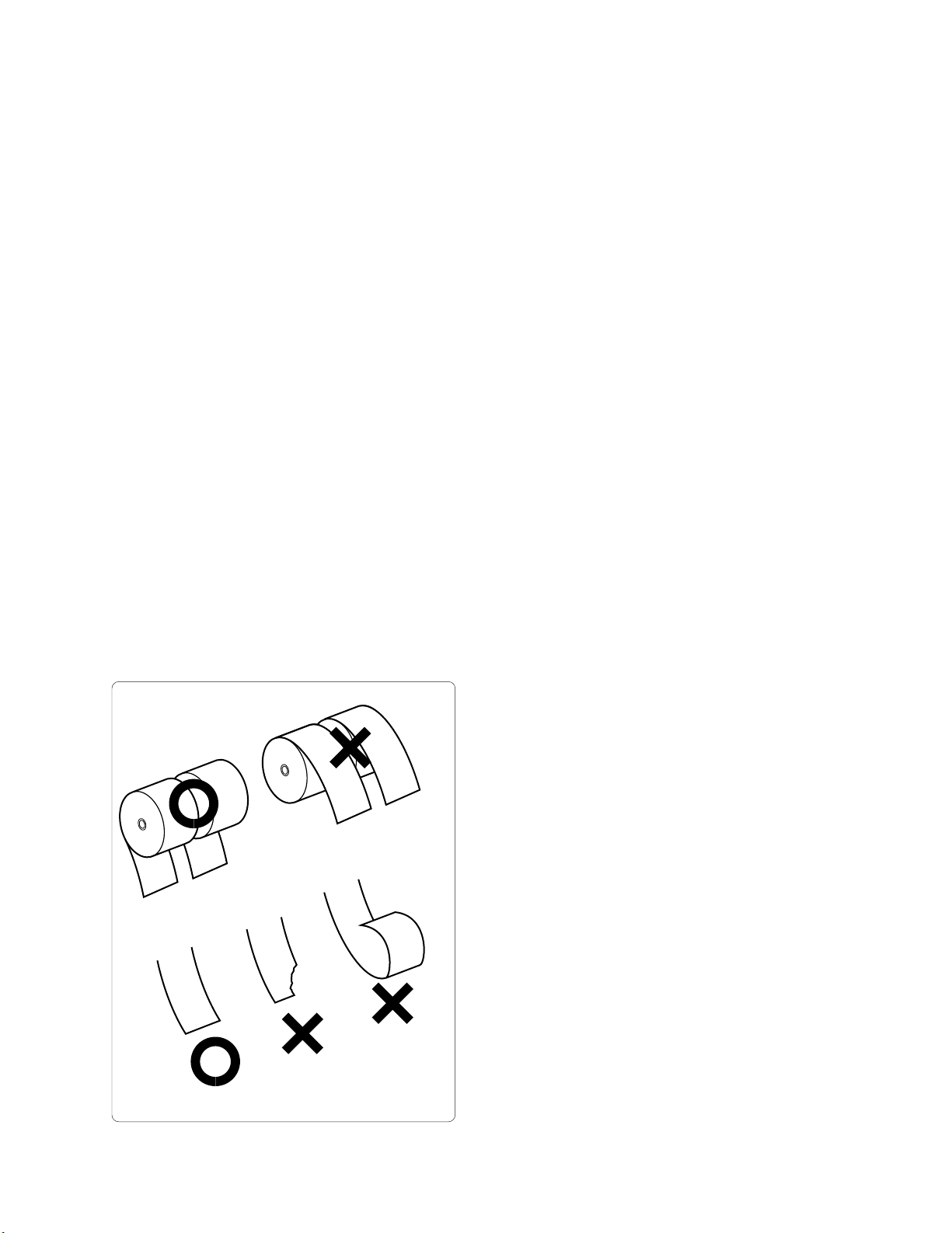
(6) Loading paper
Cut the tip of the paper in a straight line and
make sure that the paper is not frayed, folded,
or creased.
When the paper emerges from above the
print head, grasp it and pull it out slightly, to
verify that it is set straight.
(7) Removing paper
Remove the paper only after printer operation
has ceased.
Pull the paper straight out in the same direction
which it emerges from the printer.
o: correct
u : incorrect
1
Page 4

CHAPTER 2 . Specifications and Operation Principles
2-1 General Specifications
Printing method
Printing direction
Printing speed
Print format
Paper feed
Print head
Detection
functions
Paper feed
solenoid
Print solenoid
Total number of dots
Basic character configuration
Basic number of columns
Character dimensions
Column spacing
Paper feed principle
Paper feed pitch
Fast-forward speed
Inking
Number of wires
Wire diameter
Wire pitch
Dot pulse
Reset pulse
Home position
Validation
Near end
Drive voltage
Resistance
Drive voltage
Resistance
Rating
Serial impact dot matrix printer
Bi-directional printing
Approx. 3.0 lines/second m10%
Receipt side: 108 dots/216 positions
Journal side: 108 dots/216 positions
Validation: 248 dots/495 positions
7 x 7 or 7 x 9 (half-dot)
Receipt: 24
Journal: 24
Validation: 55 (1line)
1.36 (W) x 2.4 (H) mm (7 x 7 dots)
1.36 (W) x 3.1 (H) mm (7 x 9 dots)
1.59 mm
Friction feed, separate for receipt and journal
4.23 mm m10% (1/6 inch)
Approx. 30.0 lines/second
Dedicated ribbon cartridge (monochrome: purple)
9
Ø 0.3 mm
H: 0.176 mm, V: 0.353 mm
Photo interruptor
Photo interruptor
Photo interruptor
Photo interruptor
Micro switch
24.0 V DC m10%
˚C
34 ohms m10% (at 25
)
24.0 V DC m10%
˚C
8.25 ohms m10% (at 25
)
RemarksItem
24.0 V DC, 25˚C, continuous printing
Character spacing: 2 positions
Option
Motor
Type
Drive voltage
Peak current
Average current
DC brush motor
24.0 V DC m10%
Approx. 1.6 A
Approx. 250 mA
2
At startup with 24.0 V DC, 25˚C
During continuous
printing with 24.0 V DC,
25˚C
Page 5

Rating
Printer paper Width: 44.5 0.5 mm, outer diameter: max. Ø 83 mm
Take-up device
Connection principle
Service life
Ambient
conditions
Dimensions
Roll paper
Validation paper
Mechanism
Head
Operation
environment
Storage
environment
135 - 210 mm (W) x min. 70 mm (H) Single-line validation
Built-in
Pin connector
MCBF 4 million lines, maximum 8 million lines
100 million characters (2 million dots/pin)
Temperature: 0 to 50˚C
Humidity: 10-90% RH, above 39˚C equivalent to 40˚C 85% RH
Temperature: -25 to +70˚C
Humidity: 40˚C 90% RH, 96 hours
150 (W) x 230.3 (D) x 150.7 (H) mm (Type A)
150 (W) x 234.6 (D) x 123.7 (H) mm (Type B)
RemarksItem
No condensation
To be stored with ribbon
cartridge removed
Including take-up
device
Weight
Approx. 1180 g
3
Page 6
)
2-2 Mechanism Outline
g
The mechanism of this printer can be divided
into 9 blocks.
• Drive force transmission assembly
• Sensor assembly
• Print head assembly
• Paper feed assembly
• Ribbon cassette assembly
• Paper take-up assembly
• Frame
• Motor assembly
For information on peripheral circuitry
connected to this printer, please refer to the
respective documentation.
2-3 Mechanism and Operation
Principles
This section explains the construction and
operation of 8 out of the 10 blocks listed above
(excluding the frame and motor assembly).
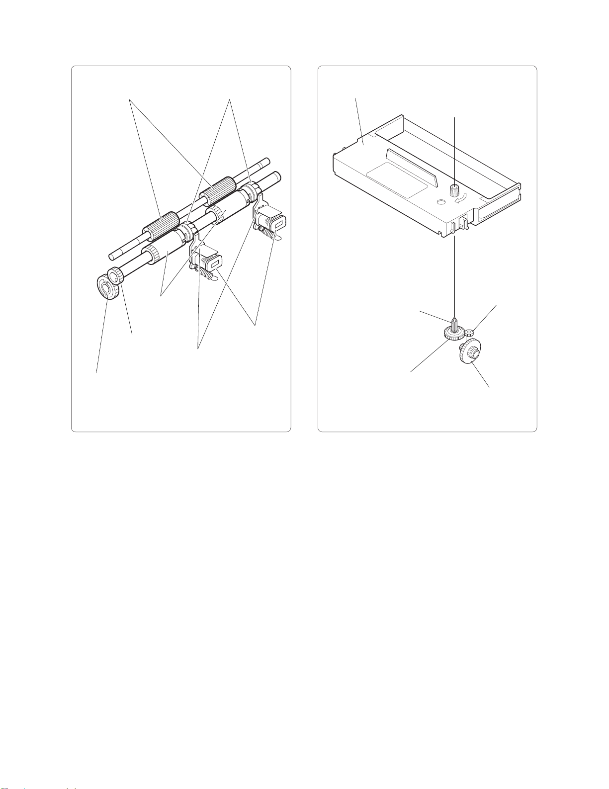
2-3-1 Drive Force Transmission Assembly
The drive force of the motor assembly is
transmitted to the various parts as follows. Print
head via bevel gear, Paper feed, via PF gear,
Ribbon cassette via worm wheel, Paper take-up
assembly via winder pulley.
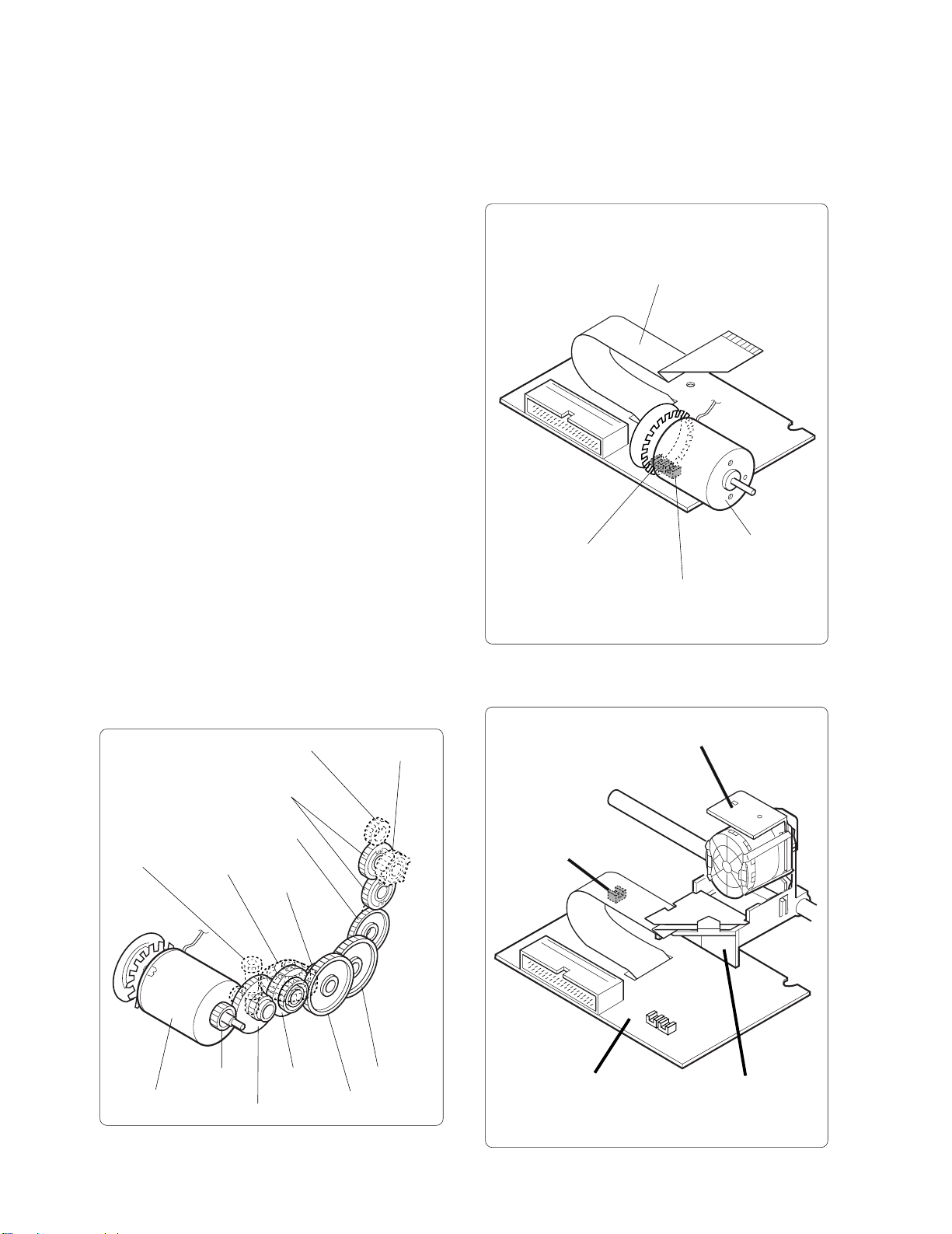
2-3-2 Sensor Assembly
The sensor assembly is comprised of 3 sensors;
the dot pulse sensor (DP), home position sensor
(HP) and reset pulse sensor (RP).
(1) Dot pulse sensor/home position sensor
Main PCB assembly
Home position sensor (HP)
Dot pulse sensor (DP
Motor assembly
(2) Reset pulse sensor
Worm wheel
Motor assembly
Idling gear 2
Idling gear 1
Bevel gear 1
Bevel gear 2
Motor gear
Reduction gear 1
PF gear
Reduction
gear 2
Reduction
gear 4
Reduction
ear 3
Winder
pulley
Reset pulse sensor (RP)
Main PCB assembly
Head assembly
Carriage
4
Page 7
g
(2) Head drive assembly
Head assembly
Carriage drive pulley
Timing belt assembly
Carriage drive pulley
Carriage
2-3-3 Print Head Assembly
(1) Print control
Printing is carried out by the print head
comprising of 9 solenoids and moving from left
to right. The print timing is controlled by the
home position sensor (HP), dot pulse sensor
(DP), and reset pulse sensor (RP).
Print head
Powered
Powered
Powered
Powered
Powered
Powered
Powered
Powered
Powered
HP
DP
Print solenoid #1
Print solenoid #2
Print solenoid #3
Print solenoid #4
Print solenoid #5
Print solenoid #6
Print solenoid #7
Print solenoid #8
Print solenoid #9
Home position sensor
Dot pulse sensor
Carriage drive gear
ear 1
Bevel
(3) Print head drive assembly
Wire spring
Print wire
Armature
Solenoid assembly
Bevel gear 2
Armature stopper
Armature springNose assembly
RP
Reset pulse sensor
5
Page 8
2-3-4 Paper Feed Assembly
g
(1) Paper feed mechanism
2-3-5 Ribbon Cassette Assembly
(1) Ribbon cassette feed mechanism
Pressure rollers
Idling gear 2
PF gear
PF roller
assembly
PF latches
PF armature
PF solenoid
assembly
Ribbon cassette
Ribbon drive shaft
Ribbon drive gear
Worm wheel
Reduction
ear 1
6
Page 9
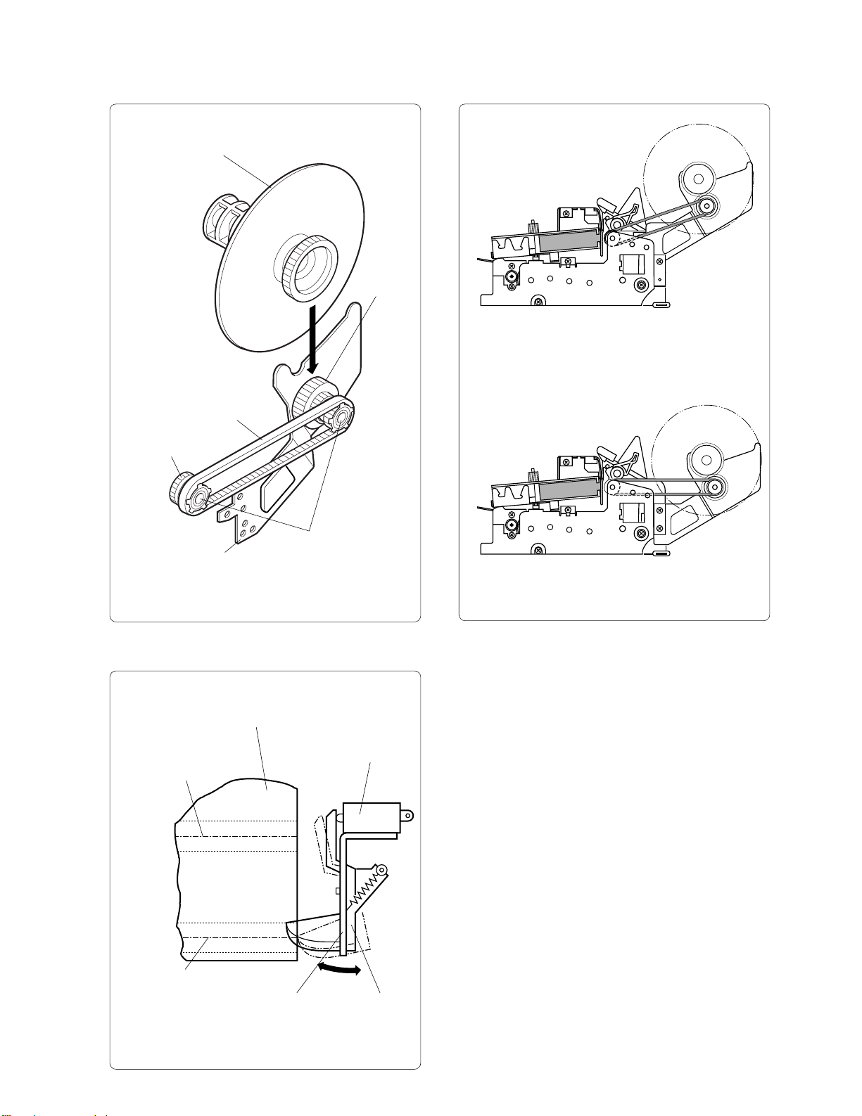
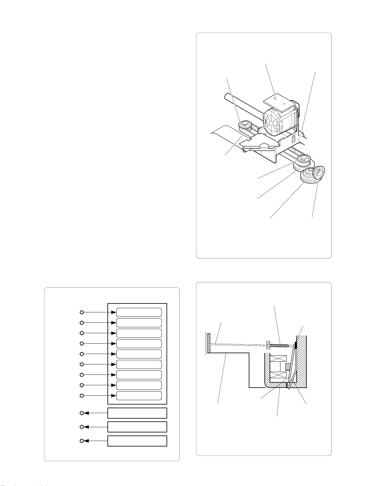
2-3-6 Paper Take-up Assembly
(1) Paper take-up mechanism
Spool
Winder timing belt
Idle gear 2
(3) Take-up mechanism types
Spool gear
Type which is the same height as the main unit
Spool holder assembly
(2) Near-end detection mechanism
Roll paper
Roll paper core
hole center
(when diameter is large)
Winder pulleys
Type which is lower than the height of the main unit
Microswitch
Roll paper core
hole center
(when diameter is small)
End switch leverSwitch holder
7
Page 10
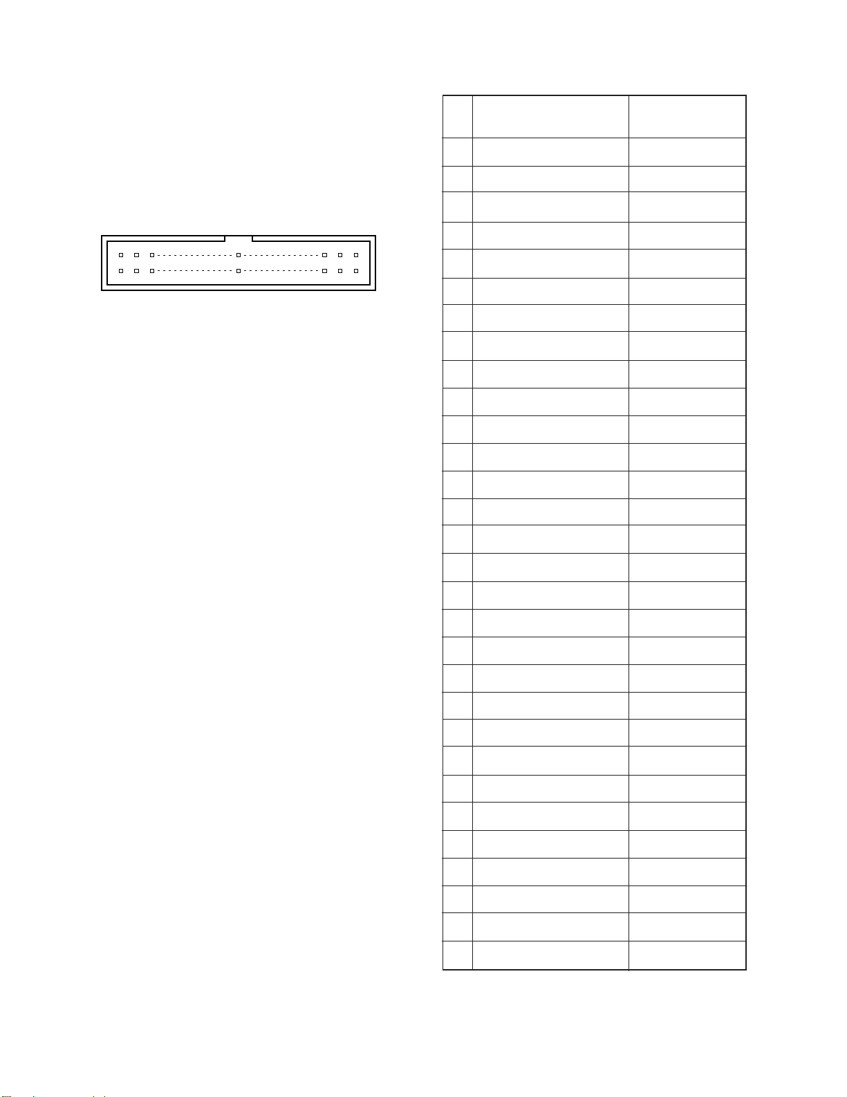
2-4 Connectors
2-4-2 Terminal Functions
2-4-1 Terminal Layout
Connector type
Printer side: Molex 5342-30T2
Host side: Molex 5320-30AT2
Pin arrangement diagram
29
30
Pin
no.
1
2
3
1
4
5
2
6
7
8
9
10
11
12
13
14
Terminal name Function
Print solenoid #3
Motor (-) VM COM.
VM COM.
Print solenoid #7
Motor on/off signal
Print solenoid COM.
Home position sensor output
Print solenoid COM.
VS
VS
Dot pulse sensor output
Print solenoid #5
Motor (+)
+VM (+24 V)
Print solenoid #2
—
Print solenoid #1
—
Multi-line validation
SOL. (option)
15
16
17
18
19
20
21
22
23
24
25
26
27
28
29
Print solenoid #9
—
Print solenoid COM.
—
Print solenoid #8
Paper feed solenoid (J)
Print solenoid #4
Paper feed solenoid (R)
Print solenoid COM.
GND
Print solenoid #6
Reset pulse sensor output
—
—
+5 V
VS
VS
30
—
8
Page 11
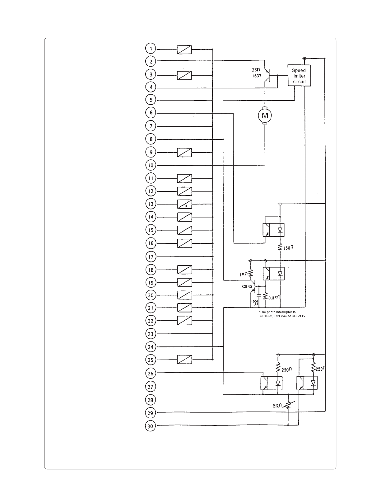
2-4-3 Terminal Circuit Diagram
Print solenoid #3
Motor (-) 24 V GND
Print solenoid #7
Motor ON/OFF signal
Print solenoid COM. (VS)
H.P. (home position pulse)
Print solenoid COM. (VS)
D.P. (dot pulse)
Print solenoid #5
Motor (+) (+24 V)
Print solenoid #2
(reserved)
Print solenoid #1
(reserved)
Print solenoid #9
(reserved)
Print solenoid COM. (VS)
Blank
Print solenoid #8
Paper feed solenoid (J)
Print solenoid #4
Paper feed solenoid (R)
Print solenoid COM. (VS)
GND
Print solenoid #6
RP (reset pulse)
Blank
Blank (RP)
+5 V
Blank
9
Page 12
CHAPTER 3. Disassembly and Assembly
Please observe the following precautions when
performing maintenance.
Note
(1) If the unit is working properly, do not
disassemble, reassemble, or adjust it
unnecessarily. The adjustment screws in
particular should not be loosened needlessly.
(2) After servicing, double-check that the unit
has been assembled correctly before turning
the power on.
(3) Never attempt to print when printer paper is
not loaded.
(4) Verify that the printer paper is loaded
correctly.
(5) When servicing the unit, take care not to
leave any screws or other loose parts in the
unit.
(6) When disassembling and reassembling the
unit, take care not to place strain on any
connecting wires, and check that the wires
are not damaged or routed incorrectly.
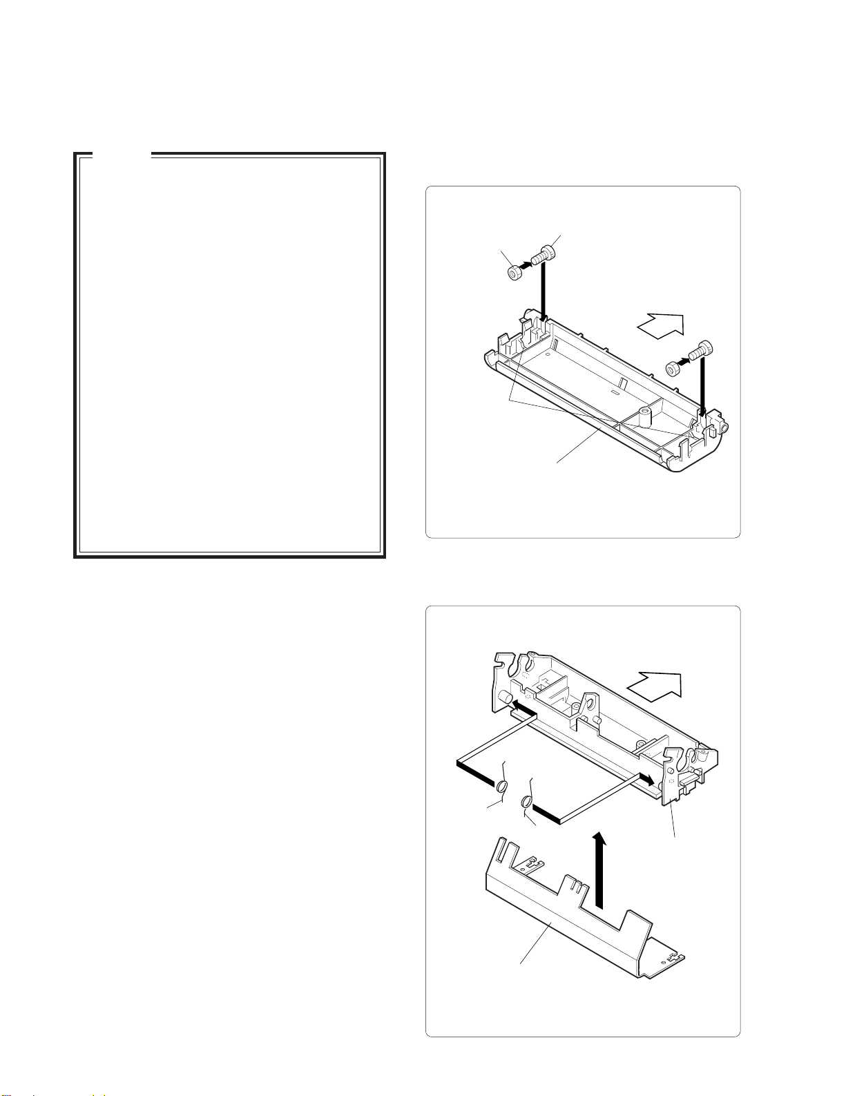
(1) Screw nuts on fastening screws (M3x10 hex socket
screws) and insert screws into paper guide (U). Make
sure that nuts fit snugly into V-shaped cutouts on
paper guide (U).
Fastening screw
Nut
Rear
V-shaped cutout
Paper guides (U)
3-1 Required Tools
1. Phillips screwdriver 8. Tester
2. Flatblade screwdriver 9. Oscilloscope
3. Pincette 10. Thickness gauge
4. Mini radio pliers (0.5 mm)
5. Oil brush 11. Dial tension gauge
6. Mini nipper (30 - 50 gf)
7. Hex wrench
(nominal 2.5)
3-2 Disassembly Procedure
Remove the parts from the frame in the opposite
order from the steps described in "3-3 Assembly
Procedure".
3-3 Assembly Procedure
The description of the assembly procedure
assumes that the individual assemblies are
complete. For information on the procedures for
individual assemblies, please refer to "Section 5
Parts List". The part names used in the
explanatory text are those indicated in Section 5
“Parts Lists”. These part names are used
commonly throughout this service manual.
(2) Fit pressure roller springs (L) and (R) onto both sides
of PF housing and set platen assembly in place.
Rear
Pressure roller
spring (L)
Platen assembly
Pressure roller
spring (R)
PF housing
10
Page 13

(3) Fit PF housing with mounted platen assembly into
paper guide (U) and fasten it with fastening screws
(A) (M3x6) and other fastening screw (M3x8).
Note: 1. When performing assembly procedures,
push the PF housing down until it is secured
by the four hooks on the paper guide (U).
2. Tighten the mounting screws (A) only after
adjusting the head gap.
Fastening screw (A)
PF housing
Hooks
Paper guide (U)
Rear
Hooks
(4) Apply Moly LG-S No. 1 to entire clutch spring area
on receipt side of PF shaft.
Note: 1. The PF shaft should have the slit on the
journal side and should not be on the
receipt side.
2. Apply the Moly LG-S No. 1 at about 30
mm from the tip of the receipt side.
(5) Apply Moly LG-S No. 1 to the inside of PF clutch
spring 2 and mount it on the clutch spring section
on the receipt side of the PF shaft.
Note: To facilitate mounting the spring, rotate it
in the direction where the spring
compresses while pushing it in.
(6) Mount PF roller assembly and journal PF latch onto
PF shaft from journal side.
Note: Pay attention to the mounting orientation
of the PF roller assembly and the PF latch.
Receipt side
PF clutch spring 2
Approx. 30 mm
Apply Moly LG-S No. 1
PF shaft
Receipt PF roller assembly
(7) Apply Moly LG-S No. 1 to the entire clutch spring
mounting section on the journal side of the PF shaft.
Note: Apply the Moly LG-S No. 1 at about 60
mm from the tip of the journal side.
(8) Fit the PF clutch spring onto clutch spring section
on journal side of PF shaft.
Note: To facilitate mounting the spring, rotate it
in the direction where the spring
compresses while pushing it in.
(9) Apply Mobile 1 to the PF shaft on the right and left
of the PF clutch springs.
Note: 1. Apply Mobile 1 for a width of about 5 mm,
starting about 10 mm from the right edge
of the PF clutch spring. This is the
mounting position for the PF roller
assembly.
2. The PF latch and PF clutch spring are
different on the receipt side and journal
side.
Receipt side: PF latch 2 (milk white)
PF clutch spring 2 (0.5 mm
dia.)
Journal side: PF latch 2 (black)
PF clutch spring (0.6 mm
dia.)
Journal side
Slit
Journal PF latch
11
Page 14

g
(10) Mount the PF latch 2 onto PF shaft from the receipt
side, and the PF roller assembly from the journal side.
Receipt side
PF latch 2
Journal side
5mm
Apply Mobile 1
PF latch
10mm
PF clutch spring 2
(Apply Moly LG-S No. 1
to outer circumference)
(Apply Moly LG-S No. 1
to outer circumference)
5mm
PF clutch spring
(11) Engage the PF roller assembly, PF latch and PF latch
2 with PF clutch spring and PF clutch spring 2,
respectively.
Note: There are protrusions at both ends of the
PF clutch springs. Match these to the slits
on the PF roller assembly and the PF latch.
5mm
Apply Mobile 1
10mm
5mm
PF roller assembly
(12) Insert the PF shaft assembly into the PF housing
and apply ORELUBE G-1/3 to the left and right
fixing lever (L)and (R).
Note: When mounting the PF shaft assembly,
match the PF roller assembly and PF latch
position to the platen width of the PF
housing.
Apply ORELUBE G-1/3
PF shaft assembly
Platen
Rear
Apply ORELUBE G-1/3
PF housin
PF latch
(PF latch 2)
PF clutch spring
(PF clutch spring 2)
Protrusion
Slit
Protrusion
PF roller assembly
Slit
12
Page 15

(13) Mount fixing levers (L) and (R) and PF gear on to
y
the PF shaft assembly, and fasten with E-rings (E4).
(14) Attach the fixing lever spring to fixing levers (L)
and (R).
(15) Insert the paper guide spring into pressure roller
shaft assembly.
Note: Pressure roller shaft assembly refers to
the pressure roller shaft with mounted
pressure rollers.
(16) While pushing the pressure roller springs (L) and
(R) towards the front side, mount the pressure
roller shaft assembly in the PF housing.
Note: After mounting, verify that the pressure
roller springs (L) and (R) are firmly
engaged in the grooves of the pressure
roller shaft assembly.
(17) Apply FLOIL G-337 to the PF armature tip. Then
mount the PF solenoid assembly to the PF housing
and fasten it with fixing screws (M3x8).
Fixing screws
Apply
FLOIL G-337
PF solenoid
assembly
Rear
PF housing
E-ring
Pressure
roller spring (L)
Fixing
lever spring
PF shaft
assembly
Groove
(Apply ORELUBE G 1/3)
Pressure roller
shaft assembly
(Apply ORELUBE G 1/3)
Fixing
lever (L)
Groove
Fixing lever (R)
Rear
PF housing
Pressure
roller spring (R)
Paper
guide spring
PF gear
E-ring
Fixing
lever spring
(18) Install the pull paper guide to the pressure
roller shaft assembly.
Note: When installing, engage one end of the
paper guide spring in the top right cutout
of the pull paper guide and the other end
in the slit of the PF shaft assembly.
Cutout
Pull paper guide
Rear
Paper guide spring
Pressure roller
shaft assembl
13
Page 16

(
)
(19) Install four paper side guide plates on the bottom
g
of paper guide (U).
(23) Apply ORELUBE G-1/3 to the pivot of the main
frame assembly. Mount the carriage drive gear and
carriage drive pulley and fasten with E-ring (E2.5).
Rear
Paper guide (U)
Paper side
uide plates
(20) Insert the washer and spool spring into the spool
gear assembly and apply Moly LG-S No. 1.
Note: 1. The spool gear assembly refers to the spool
gear with inserted spool spring bush.
2. When installing, the hook of the spool
spring should face forward, and the spring
should be turned counterclockwise.
(21) Apply Moly LG-S No. 1 to the outer circumference
of the spool spring and install the winder pulley.
(22) Apply Moly LG-S No. 1 to the pivot of the spool holder
assembly. Fit the spool gear assembly with the mounted
winder pulley in and fasten it with E-ring (E3).
Carriage drive gear
Main frame
assembly
E-ring
Carriage drive pulley
Apply ORELUBE G-1/3
Pivot
Rear
Pivot
E-ring
Winder pulley
Spool gear
assembly
Spool holder assembly
(Apply Moly LG-S No. 1 )
Apply Moly LG-S No. 1
Washer
Spool spring
14
Page 17

(24) Apply ORELUBE G-1/3 to the pivot of the pulley
drive assembly. Mount the carriage drive pulley and
fasten with E-ring (E2.5).
(25) Align the positions of the mounted carriage drive
pulley cutout and the cutout of the other carriage drive
pulley andmount timing belt assembly.
(26) Provisionally fasten the pulley drive assembly with
M3 washer and fastening screw (M3x5).
(27) Move the carriage drive pin to the center of the pulley
drive assembly, perform the tension adjustment to
determine the position of pulley drive plate assembly,
and fasten the assembly. Use a dial tension gauge
for the tension adjustment. When pushed with a force
of 30 gf, the timing belt displacement must be 2 mm.
(28) Apply ORELUBE G-1/3 to the fastening boss of the
stamp lever plate in the paper guide (L) assembly and
to the three slits contacting the plate.
Note: Paper guide (L) assembly refers to the
paper guide (L) with pressure rollers,
paper pressure sheet, 1-line validation
PCB assembly and validation guide plate
installed.
Rear
Paper guide (L)
assembly
Fastening screw
Washer
Main frame
assembly
Apply
ORELUBE G-1/3
Pulley drive plate assembly
Pulley drive
plate assembly
Position
adjustment
E-ring
Carriage drive pulley
2mm 30gf
Timing belt
assembly
Rear
Carriage drive
assembly
Carriage drive
pin center position
(Apply ORELUBE G-1/3)
Boss
(29) Install the paper guide (L) assembly in the main frame
assembly and fasten with fastening screws (M3x6).
Fastening screw
Stamp lever plate
Paper guide (L)
assembly
Rear
15
Main frame assembly
Fastening
screw
Page 18

y
(30) Mount the motor assembly and motor spacer on to
the right side of the main frame assembly and
fasten with fastening screws (M3x5).
Note: Mount the motor so that the lead wires are
on the bottom side.
Motor assembly
Rear
Motor spacer
Rear
Main frame
assembly
(31) Apply ORELUBE G-1/3 to the three pivots on the
right side of the main frame assembly.
Fastening
screws
Rear
E-ring
Main frame
assembly
Motor gear
Bevel gear 1
Bevel gear 1
pivot
E-ring
(34) Install the idle gear 1 and idle gear 2 and the winder
pulley assembly.
Note: 1. Winder pulley assembly refers to the
winder pulley with the idle gear 2 installed.
2. Mount the winder gear 2 and the winder pulley
assembly while disengaging the securing
hook.
Rear
Winder pulley
assembly
Pivot
Main frame
assembly
(Apply ORELUBE G-1/3)
(32) Mount the motor gear on the shaft of the motor assembly.
(33) Install the bevel gear 1 and fasten with E-ring (E2) over
the bevel gear 1 pivot.
16
Main frame
assembl
Idle gear 2
Securing hook
Idle gear 1
Page 19

(35) Apply ORELUBE G-1/3 to the four pivots on the
y
frame (R) support plate assembly and on the ribbon
drive shaft mount hole.
Bevel gear 2
assembly
Reduction gear 2
Reduction gear 4
Rear cushion
Apply ORELUBE G-1/3
Apply ORELUBE G-1/3
Frame (R) support
plate assembl
(36) Apply ORELUBE G-1/3 to the ratchet on inside of
ribbon gear and mount on ribbon drive shaft. Then
install the frame (R) support plate assembly and
fasten with E-ring (E4).
E-ring
Ribbon gear
Ribbon drive shaft
E-ring
Washer
Reduction gear 1
Frame (R) support
plate assembly
(41) Rotate the motor gear so that timing disc home
position slit is at the topmost position. Then rotate
bevel gear 1 so that the carriage drive pin is at the
horizontal left most position.
Carriage drive pin
horizontal left most position
Rear
Frame (R) support
plate assembly
Apply ORELUBE
G-1/3 to ratchet
(37) Combine reduction gear 4 and the bevel gear 2
assembly, and install.
Note: Bevel gear 2 assembly refers to reduction
gear 3 with installed bevel gear 2.
(38) Mount the reduction gear 2.
(39) Install the reduction gear 1 and slide washer, and
fasten with E-ring (E2).
(40) Install the rear cushion.
Note: Install the rear cushion from the side
opposite the slit.
Home position slit
top most position
Timing disc
Bevel gear 1
Motor gear
17
Page 20

(42) Pull the winder timing belt onto the winder pulley
y
assembly.
(43) Install the frame (R) support plate assembly on to the
main frame assembly and fasten with fastening screws
(M3x8).
Rear
Winder pulley
assembly
Rear cushion
Rear
Winder
timing belt
Main frame
assembly
Frame (R) support
plate assembl
Fastening
screws
(44) Apply EPINOC AP-1 to the gears of the worm
wheel assembly.
(45) Set the worm wheel assembly in the worm wheel
assembly mounting position on the frame (R)
support plate assembly.
(46) Mount E-ring (E2) on to the worm wheel pivot.
(47) Apply EPINOC AP-1 to the worm wheel pivot.
(48) Insert the worm wheel pivot from the hole in the
bottom of the main frame assembly and install
in the worm wheel assembly.
(49) Push the worm wheel pivot into the hole of the ribbon
pivot bushing and fit the bushing into the frame (R)
support plateassembly mount hole. Then fasten
with E-ring (E1.5).
(50) Mount the rear cushion on the main frame assembly.
Note: Install the rear cushion from the side
opposite the slit.
Main frame
assembly
Frame (R) support
plate assembly
Ribbon pivot bushing
Gear
(Apply EPINOC AP-1)
Worm wheel
assembly
Worm wheel pivot
(Apply EPINOC AP-1)
E-ring
Mount
hole
E-ring
(51) Apply EPINOC AP-1 to the moving part of the carriage
on the main frame assembly, and apply ORELUBE G-1/3
to the carriage drive pin of the timing belt assembly.
Carriage drive pin
(Apply ORELUBE G 1/3)
Carriage moving part
(Apply EPINOC AP-1)
Rear
Main frame
assembly
18
Page 21

(52)
Mount the felt on the carriage and install in the
main frame assembly with the carriage shaft
inserted from the left side.
Note:1.Moisten the felt with Mobile 1.
2. When installing, start from a position
where the carriage drive pin is parallel to
the receipt side wall of the main frame
assembly (see illustration).
3. Insert the carriage shaft from the nonchamfered end.
(53) Fasten the carriage shaft to the main frame assembly
with the washer and fastening screw (M3x3).
Fastening
screw
Main frame
assembly
PF housing
assembly
Rear
Boss
(There is a boss in the
opposite side as well)
Fastening
screw
Fastening screw
washer
Carriage
shaft
Fastening
screw
Carriage drive pin
Main frame assembly
Chamfered section
Carriage
Carriage shaft
Screw mount
hole
Felt
(54) Apply ORELUBE G-1/3 to two the PF housing
assembly mount holes (2 locations) on the main frame
assembly. Then install the PF housing assembly and
fasten with the fastening screws (M3x6).
Note: 1. The PF housing assembly has been built
in steps (1) - (27).
2. When installing the PF housing assembly,
fit the left and right boss into the mount
hole on each side in sequence.
Mount holes
(Apply ORELUBE G-1/3)
(55) Install the main PCB assembly from the bottom of
the main frame assembly.
Note: 1. Install after moving the carriage to the
center.
2. When installing, pass the lead wires of the
motor assembly through the rectangular
cutout in the PCB to the bottom side.
3. Take care that the ceramic condenser and
transistor on the PCB around dot pulse
sensor do not come into contact with the
motor assembly timing disc.
(56) Mount the FFC fixer plate on the main PCB assembly
and fasten with fastening screw (M3x6).
19
Page 22

(57) Place the insulating sheet and transistor on the main
PCB assembly, and fasten with the fastening screw
(M3x10).
Note: When installing, bend the transistor legs
at a right angle, in alignment with the
soldering holes on PCB.
(58) Screw the nut (M3) on to the fastening screw (M3x10)
and fasten the FFC fixer plate.
Fastening screw
Transistor
Insulating sheet
Carriage
Rear
Main frame assembly
Soldering holes
FFC fixer plate
Nut
Main PCB assembly
Ceramic condenser
Transistor
Rectangular cutout
Dot pulse sensor
Fastening screw
20
Page 23

(61)
Loosen the fastening screw of the frame (R) support
plate assembly and engage the winder timing belt
on the winder pulley of the winder assembly. Then
engage the winder assembly boss in the main frame
assembly hole, and fasten with fastening screws
(M3x6). Finally tighten the loosened screw again.
Note: The winder pulley has been assembled
with steps (20) - (22).
Head cable
Cable
fixing sheet
Head assembly
Rear
Main frame assembly
Frame (R) support
plate assembly
Rear
Winder timing belt
Loosen
Winder assembly
Boss
Fastening
screws
Winder
pulley
(62) Insert the head cable from the main PCB assembly
into the head assembly.
(68) Mount the head assembly in the carriage.
Note: 1. When installing, insert cable fixing sheet
into slit of carriage and mount carriage on
head assembly with cable grasped
between sheet and carriage.
2. Take care not to scratch the head cable.
Head cable Slit Carriage
(64) Install the ribbon plate assembly in the main frame
assembly and fasten with the fastening screws (M3x5).
Note: 1. Ribbon plate assembly refers to the ribbon
plate with blind label and ribbon cassette
cushion.
2. When installing, engage the protrusion on
the ribbon plate assembly in the mount
hole on the main frame assembly, and
then slide the assembly to the right.
Mount holes
Rear
Ribbon plate assembly
21
Fastening screw
Protrusions
Main frame
assembly
Page 24

(65) Insert the ribbon plate spring in the ribbon plate
assembly and the main frame assembly front center.
(66) Mount the head cover on the main frame assembly
and fasten with fastening screws (M3x5).
Note: While installing, the PF housing assembly
should be open.
Fastening screw
Rear
(68)
Install the grounding spring in the PF housing
assembly.
Note: 1. Insert the grounding spring between the
right side of the PF housing assembly and
the right side plate of the main frame
assembly.
2. Fit the bent sections of the grounding
spring into the positioning slits on the PF
housing assembly.
3. The bent tip of the grounding spring must
contact the PF shaft.
Head cover
Ribbon plate spring
PF housing assembly
Fastening
screw
(67) Mount the manual cutter on the 2-station housing cover.
2-station housing cover
Manual cutter
Protrusion
(Apply EPINOC AP-1)
Right
side plate
Positioning slit
PF housing assembly
Bent tip
(Apply EPINOC AP-1)
Grounding spring
PF shaft
Rear
Rear
22
Page 25

(69) Install the 2-station housing cover on the PF housing
assembly and fasten with fastening screws (M3x8).
Fastening screw
PF housing
assembly
2-station
housing cover
Rear
Fastening
screw
3-4 Adjustment
There are six adjustment items for this printer, as
listed below. Perform the adjustments in the listed
order.
(1) Print speed adjustment
(2) Platen/head gap adjustment
(3) Bidirectional printing shift adjustment
(4) Reset pulse (RP)/home position (HP)
waveform check
3-4-1 Print Speed Adjustment
(1) Procedure
Perform the bi-directional printing and use an
oscilloscope to measure cycle A of the reset pulse
(RP).
(70) Install the ribbon cassette.
Ribbon cassette
Rear
RP
A
(2) Check points
RP waveform: Connector pin 26
GND: Connector pin 24
Note Perform the adjustment under the
following conditions.
•Ribbon cassette: Loaded
•Printer paper: Loaded
•Motor drive voltage: 24V
•Ambient temperature: Normal room
temperature
•Printing mode: Continuous
printing
23
Page 26

(3) Adjustment
Adjust the print speed adjustment VR on the
solder side of the main PCB assembly until cycle
A falls within the range shown below.
Value of A Adjustment procedure
3-4-3 Bi-directional Printing Shift Adjustment
(1) Procedure
Perform bidirectional printing. Judge the results
and rotate the motor shaft while holding the
timing disc stationary, until there is no printing
shift.
601m-733ms
Print speed
adjustment VR
When A is out of range: Perform
adjustment by turning the VR.
Validation sensor
adjustment VR
Main PCB assembly
3-4-2 Platen/Head Gap Adjustment
(1) Procedure
1. Remove the 2-station housing cover.
2. Loosen the two fastening screws of the PF
housing platen assembly.
(2) Adjustment
Use a thickness gauge to measure the gap between
the head assembly and the platen assembly.
Adjust the two adjustment screws (M3x10 hex
socket screws) on the rear until the gap is within
the range shown below.
(2) Adjustment
Hold the timing disc stationary with a flat object
(such as the grip of a pincette). Grasp the motor
shaft with a pair of radio pliers and rotate the shaft
in the direction as indicated in the table below.
Print condition Adjustment procedure
Rotate shaft in clockwise
direction until shift is
within 1 dot.
Rotate shaft in
counterclockwise
direction until shift is
within 1 dot.
Gap Adjustment procedure
When gap is out of range:
0.5 - 0.55 mm
Adjust the gap by turning two
adjustment screws on rear.
Note 1. Adjust the gap in three locations (right,
left, center).
2. Retighten the loosened screws.
24
Page 27

3-4-4 RP/HP Waveform Check
(1) Procedure
Perform bi-directional printing and use an
oscilloscope to measure the phase shift A between
the reset pulse (RP) waveform and home position
pulse (HP) waveform.
OFF OFFON
RP
A
HP
DP
OFF
(2) Check points
RP waveform: Connector pin 26
HP waveform: Connector pin 6
GND: Connector pin 24
(3) Adjustment
Verify that the value of A is between 3 and 8 ms.
ON
25
Page 28

3-5 Head Assembly Replacement
Head cover
3-5-1 Disassembly Procedure
(1) Remove printer from the POS/ECR.
(2) Remove the ribbon cassette.
(3) Push the right and left fixing lever and open the PF
housing assembly.
Ribbon cassette
Rear
PF housing
assembly
Fixing
lever
Rear
Fastening
screw
Fastening
screw
(5) Move the ribbon plate as follows.
[1] Remove the ribbon plate fastening screw (M3x5).
[2] Raise the ribbon plate (rear side) and slide to left.
[3] Raise the ribbon plate (front) and disengage
from the main frame assembly protrusion.
[4] Raise the ribbon plate and rotate counterclockwise
around the ribbon drive shaft, until the head
cable is visible.
Note: Because the ribbon plate is tensioned by
the ribbon plate spring, care must be
taken not to damage the ribbon drive shaft
when turning the plate.
(4) Remove fastening screws (M3x5) and remove the head
cover.
26
Page 29

Ribbon plate
Fastening
screw
1
Ribbon plate
spring
Ribbon plate
2
Protrusion
4
Ribbon drive
shaft
3
Rear
(6) Grasp the left side of the cable fixing sheet and raise
to the left to remove.
Note: The cable fixing sheet is thin and small.
Take care not to drop it into the printer or
otherwise lose it.
(7) Grasp the protrusion on the head assembly and lift up.
(8) When the head assembly is removed from the carriage,
pull out the head cable and disconnect.
3-5-2 Assembly Procedure
(1) Plug the head cable into the head assembly connector.
Note: Make sure that the head cable is pushed
fully into the connector.
(2) Insert the head assembly into the carriage guide. Just
before the assembly is fully seated, push the bent
section of the head cable into the carriage slit.
Note: Take care not to damage the head cable.
(3) Push the head assembly further in until it locks into
place.
(4) Check orientation of the cable fixing sheet and
insert the sheet into the carriage slit.
Head assembly
Head cable
Cable fixing
sheet
Rear
Guide
Head assembly
Head cable
Cable fixing
sheet
Head cable Slit Carriage
Protrusion
Head cable Slit Carriage
Rear
27
Page 30

(5) Reinstall the ribbon plate by reversing the disassembly
procedure.
Note: Make sure that ribbon plate fastening
screw section is on the inside of the main
frame assembly.
Rear
Fastening
section
Fastening
screw
Ribbon plate
spring
Ribbon plate
4
3
1
Fastening screw
Head cover
Protrusion
Main frame
assembly
Rear
Fastening
screw
Protrusion
Ribbon plate
2
Ribbon drive
shaft
(6) Install the head cover.
Note: When installing, make sure that the head
cover left/right positioning part and the main
frame assembly left/right protrusion are
fully matched.
(7) Fasten the head cover with 2 screws.
(8) Open the PF housing assembly.
(9) Insert the ribbon cassette.
(10) Mount the printer in the POS/ECR system.
Ribbon cassette
Rear
PF housing
assembly
28
Page 31

If not rotating, replace motor.
Check points Countermeasure
Apply rated voltage (24 V DC) to motor lead solder
If not supplied, repair printer control
section.
points on main PCB assembly (+: red, -: black) and
check whether motor turns.
Measure voltage between pins 10 (+) and 2 (-) of
connector on main PCB assembly and verify that 24 V
If there is no conductivity, replace
main PCB assembly.
Remove any jammed paper or foreign
objects.
Replace print head assembly and
ribbon cassette.
DC is supplied.
Check conductivity between pin 10 of connector on
main PCB assembly and red motor lead, and pin 2 and
black motor lead.
Open PF housing and check for jammed paper or foreign
objects.
Check whether head wire is tangled in ink ribbon or
paper.
If not moving, remove any foreign
objects or replaced damaged gear.
Rotate motor gear by hand and check whether gear train
moves.
faults.
Symptom............. Begin searching with this column. If there are several symptoms, take all applicable items into consideration. This will allow you to discover a potential
When a problem has occurred, check the symptoms carefully and use the instruction in the section "4-2 Repair Steps" to isolate the problem. When the cause is found, repair
it as specified.
4-1 Repair Procedure
CHAPTER 4. Troubleshooting
problem.
Condition ............ Information given here is a precondition for determining the cause in the next column. Use the item together with the previous column to pinpoint the
Cause................... Lists conceivable causes. Select a possible cause from the list, and verify as described in the next column.
Check points ....... Perform these checks to confirm that the problem is really caused by the respective condition.
Countermeasure .. Repair the problem as described here.
By following the above procedure, effective troubleshooting is possible.
Motor is defective
Motor does not
operate.
Symptom Condition Cause
Carriage does not
move.
4-2 Repair Steps
29
Problem with voltage
applied to motor
Head movement problem
Main PCB assembly
is defective
Paper jam
Paper is jammed with ink
ribbon or print head wire.
Foreign object in gear
wheel train, or gear is
damaged.
Page 32

If there is a phase shift, reseat the time
belt assembly.
Lubricate if not sufficiently
lubricated.
If not supplied, repair the printer control
section.
Check points Countermeasure
Remove carriage and check engaging condition of
carriage drive pin and pulley.
Check whether carriage rails (front and back) are
lubricated.
Measure voltage between pins 29 (+) and 24 (-) of
connector on main PCB assembly and verify that 5 V DC
If signal is not normal, replace the main
PCB assembly.
If there is a problem, repair the printer
control section or replace the connecting
cable.
Reinsert FFC if disconnected.
is supplied.
Observe waveform of signal at pin 6 (HP), pin 8 (DP),
and pin 26 (RP) and check whether signal is normal.
Check circuit hardware of printer control section and
connection cable to printer.
Check FFC connection condition.
If operation is normal, replace the print
head assembly.
Check whether replacing print head assembly solves the
problem.
If not correct, reinsert.
If not supplied, repair the printer control
section.
If signal is not normal, replace the main
PCB assembly.
Note that if the printer control section is defective, the
head can be destroyed.
Verify that ribbon cassette is loaded correctly.
Measure voltage between pins 29 (+) and 24 (-) of
connector on main PCB assembly and verify that 5 V DC
is supplied.
Observe waveform of signal at pin 6 (HP), pin 8 (DP),
and pin 26 (RP) and check whether signal is normal.
Timing belt assembly and
pulley phase shift
Carriage actuator problem
DP/HP/RP signal problem
Motor does not
move.
Symptom Condition Cause
Carriage does not
move.
Head movement problem Print problem
Motor normal
Carriage does not
stop.
Control section problem
Head FFC disconnected
Print head assembly
is defective
Carriage operation
normal
Unit does not print
(all dots/specific
dots).
30
Ribbon cassette not
inserted properly
DP/HP/RP signal problem
Page 33

If there is a problem, repair printer
control section or replace connecting
cable.
Remove.
Check points Countermeasure
Check circuit hardware of printer control section and
the connection cable to printer.
Remove the print head assembly and check the print
section for presence of foreign objects. Check whether
Insert correctly.
the ribbon cassette is inserted correctly.
Replace ribbon cassette if there is a
problem.
Turn ribbon cassette take-up knob in arrow direction and
check knob rotation and take-up action of the ribbon.
If not rotating, remove foreign object
or replace gear if damaged.
Turn motor gear clockwise by hand and check whether
gear train moves.
Readjust the gap if necessary.
Repair the printer control section if
required.
If shift problem is cleared, perform
readjustment.
If not correct, prepare the paper tip
correctly and reinsert.
If out of range, replace with paper that
meets specified requirements.
Remove any paper scraps or foreign
object.
If out of range, replace the PF solenoid.
Check gap between print head and platen.
Check voltage and continuity of print solenoid voltage
supplied by printer control section.
Check whether shift disappears when rotating timing
disk while holding motor shaft.
Check whether paper tip is folded or not properly cut.
Check whether paper thickness, width, and roll diameter
are within specifications.
Open paper feed unit and check for jammed paper or
foreign object.
Measure whether resistance of PF solenoid is within
specifications (approx. 34 ohms).
Control section problem
Carriage operation
normal
Symptom Condition Cause
Unit does not print
(all dots/specific
Foreign object in print
dots).
section
Ribbon cassette not
inserted correctly
Ribbon cassette defective
Ribbon is not
transported.
Print is washed
out.
Print problem Paper feed problem
Foreign object in ribbon
drive mechanism or gear is
damaged.
Print head and platen gap
not correct
Control section problem
Ribbon feed is
normal.
Timing disc position
problem
Paper tip folded or not cut
correctly
Paper is not within
standard rating
Shift is greater
than 0.3 mm.
Bidirectional
printing shift
Cannot insert
paper.
31
Paper scraps or foreign
object
PF solenoid wire break
PF armature does
not operate.
Paper is not
transported at all
or erratically.
Page 34

If there is a problem, repair the printer
control section or replace connecting
cable.
If there is a paper jam, repair the paper
feed path.
If setting is incorrect, set the paper
properly.
If locked, remove foreign objects or
replace the gear if damaged.
If force is insufficient, replace the PF
slip mechanism.
If worn, replace any worn parts.
Check points Countermeasure
Check the circuit hardware of the printer control
section and the connection cable to the printer.
Check for a jam in the external paper path.
Check for a problem in the external paper setting mechanism.
Check for locking due to foreign object or damaged gear.
Check whether the PF slip mechanism has enough force
for paper feed.
Check the PF latch for wear.
If not set properly, reinsert correctly.
Check whether ribbon cassette is inserted correctly.
Replace the ribbon cassette as necessary.
If not rotating, remove any foreign
objects. If the gear is damaged, replace
the gear.
Turn ribbon cassette take-up knob in arrow direction and
check knob rotation and take-up action of the ribbon.
Turn motor gear clockwise by hand and check whether
the gear train moves.
Control section problem
PF armature does
not operate.
Symptom Condition Cause
Paper is not
transported at all
Paper jam outside printer
PF armature
or erratically.
Paper feed problem
operates.
Paper feed mechanism
is defective
Clutch mechanism is
defective
Ribbon cassette not
Paper feed amount
is too large.
Paper feed pitch is
wrong.
Ribbon is not
Ribbon feed problem
inserted correctly
Ribbon cassette is defective
Foreign object in ribbon
drive mechanism or gear
is damaged.
transported.
32
Page 35

DP-750
Parts guide
1 Mechanism etc No.1
NO. PARTS CODE
0CZC3401-637/
1
0CZE11130-05/
2
0CZE11130-06D
3
0CZE11230-08/
5
0CZE60330-00/
8
0CZE60340-00/
9
0CZM4317-02//
10
0CZNE09710-0/
20
0CZNE10201-0/
21
0CZNE10202-1/
22
0CZNE10203-0/
23
0CZNE10204-1/
24
0CZNE10206-0/
26
0CZNE10207-1/
27
0CZNE10208-1/
28
0CZNE12003-1/
29
0CZNE14104-0/
31
0CZNE14201-2/
32
0CZC4600-065/
33
0CZNE16701-0/
34
0CZNE19101-0/
35
0CZNE19102-0/
36
0CZNE20201-0/
37
0CZNE20202-1/
38
0CZNE20203-0/
39
0CZNE20205-1/
41
0CZNE23606-1/
52
0CZNE24208-0/
66
0CZNE26901-0/
71
0CZNE30701-0/
72
0CZNE30202-0/
73
0CZNE32001-0/
74
0CZNE32201-0/
75
0CZNE34102-1/
76
0CZNE43601-0/
79
0CZNE44108-1/
81
0CZNE66701-1/
84
0CZC7802-029/
87
0CZE00730-05/
88
0CZNE22005-0/
89
0CZE60320-00/
90
0CZNE64101-0/
100
0CZE40230-00/
101
0CZE11130-10/
102
0CZNE30702-0/
103
0CZT6209-01//
104
0CZNE34702-0/
105
0CZNE44707-0/
106
0CZNE11902-0/
107
0CZE50130-00/
108
0CZE00130-03/
109
0CZE60325-00/
110
0CZNE16702-0/
111
0CZNE44704-4/
112
0CZNE44702-6/
113
0CZNE10209-0/
114
0CZNE44711-1/
115
0CZNE29704-2/
116
0CZNE24702-4/
117
0CZNE24705-0/
118
0CZNE15701-3/
119
0CZNE31201-0/
128
0CZE60315-00/
129
0CZE50230-00/
220
0CZNE67906-1/
841
0CZNE66901-2/
842
PRICE
RANK
NEW
PART
MARK
AN B Transistor (2SD1637)
AD C Screw (PTH(ST),M3×5)
AD C Screw (PHT(ST),M3×6)
AD C Screw (PHT(PT),M3×8)
AD C E-ring (E3)
AD C E-ring (E4)
AH C Rear cushion
BS B SA, Head
AH C Gear, Motor
AH C Pulley, Drive, Carriage
AH C Gear, Drive, Carriage
AH C Gear 1, Bevel
AH C Gear 2, Reduction
AH C Gear 2, Bevel
AK C Gear 3, Reduction
AP C Shaft, Carriage
AH C Spacer, Motor
AU D Carriage
AP B Poly switch
AX C SA, Belt, Timing
AE C Felt
AH C Sheet, Fixer, Cable
AK C Gear 4, Reduction
AK C Gear 1, Idle
AH C Gear 2, Idle
AH C Pulley, Winder
AK C Spring, Spool
AS C Spool
AN C Belt, Timing, Winder
AV C SA, wheel, worm
AH C Gear, Drive, Ribbon
AL C Pivot, Wheel, Worm
AH C Shaft, Drive, Ribbon
AN C Plate, Ribbon
AG C Spring, Plate, Ribbon
AP D Cover, Head
BH E SA, PWB, Main
AH C Insulating sheet (S-16)
AD C Screw (PH(SW),M3×5)
AK C Pivot, Gear 1, Bebel
AD C E-ring (E2)
AH C Plate,fixer,FPC
AD C Nut(#3) (M3)
AD C Screw (PHT(ST),M3×10)
AX C Kit,wheel,worm
AB C Washer B
AP N C SA, Ribbon plate 2
AQ N D SA, Head cover
AD N C Washer,slide gear 1
AD N C Washer,plain,3
AD N C Screw (PH,M3.0×3)
AD N C E-ring (E2.5)
AN N C SA,Pplate,pulley,drive
BF N D SA,Frame,main
BC N C Frame R,side
AS N C Gear 1,reduction
AT N D SA,plate,support,frame R
AZ N C SA,Winder
AS N C SA,Holder,spool
AR N C SA,Gear,spool
BD N B SA,Motor,DC
AD N C Bushing,pivot,ribbon
AD N C E-ring (E1.5)
AD N C Washer,plain,(#2) (3)
AP C Cable, head
AR E PWB, MAIN
RANK
DESCRIPTION
– 1 –
Page 36

1 Mechanism etc No.1
DP-750
20
36
35
105
76
33
119
2
106
32
81
23
22
10
89
2
112
90
24
90
107
113
21
114
26
39
27
38
129
128
115
118
41
37
104
52
28
B
41
8
71
9
10
A
2
108
111
110
34
110
22
220
109
79
2
A
31
102
1
87
841
84
B
88
842
100
90
3
101
29
66
116
117
3
5
RCP00390
– 2 –
73
75
90
72
74
5
103
Page 37

DP-750
2 Mechanism etc No.2
NO. PARTS CODE
0CZE11130-06D
3
0CZE11230-06U
4
0CZE11230-08/
5
0CZE20130-10/
6
0CZE40130-00/
7
0CZE60330-00/
8
0CZE60340-00/
9
0CZNE20204-0/
40
0CZNE22001-0/
43
0CZNE22201-1/
45
0CZNE22203-1/
46
0CZNE22701-1/
47
0CZNE23601-1/
48
0CZNE23602-1/
49
0CZNE23603-1/
50
0CZNE23605-1/
51
0CZNE23609-0/
53
0CZNE24101-1/
55
0CZNE24103-1/
56
0CZNE24112-0/
58
0CZNE24113-0/
59
0CZNE24202-1/
61
0CZNE24205-1/
64
0CZNE24206-1/
65
0CZNE24701-1/
68
0CZNE25701-1/
70
0CZNE43101-0/
78
0CZNE44201-1/
82
0CZT6115-01//
86
0CZNE24117-0/
96
0CZNE43102-0/
97
0CZNE24201-3/
120
0CZNE22002-2/
121
0CZNE22206-0/
122
0CZNE23614-0/
123
0CZNE24203-2/
124
0CZNE24204-2/
125
0CZNE24209-1/
126
0CZNE22702-0/
127
0CZNE23612-0/
130
0CZNE66903-0/
701
0CZNE25702-0/
702
PRICE
RANK
NEW
PART
MARK
AD C Screw (PHT(ST),M3×6)
AD N C Screw (PHT(PT),M3×6)
AD C Screw (PHT(PT),M3×8)
AD C Screw (HSC,M3×10)
AD C Nut (M3)
AD C E-ring (E3)
AD C E-ring (E4)
AG C Gear, PF
AP C Shaft, Roller, Pressure
AK C Roller, Pressure
AH C Latch, PF
AP C SA, Roller, PF
AE C Spring R, Roller, Pressure
AE C Spring, Guide, Paper
AK C Spring, Clutch, PF
AD C Spring, Lever, Fixer
AE C Spring L, Roller, Pressure
AK C Sheet, Pressure, Paper
AH C Armature, PF
AH C Cutter, Manual
AS C Plate, Guide, Validation
AS C Guide, Paper, Pull
AW C Guide U, paper
AH C Plate, Guide, Paper Side
AS C SA, Platen
AX B SA, Solenoid, PF
AG C Spring, Earth
BA C Guide L, Paper
AD C Roll, Pressure
AG C Residual, solenoid
AG C Spring, earth, manual cut
BA N D Housing,PF
AP N C Shaft,PFf
AH N C Latch,PF 2
AK N C Spring,clutch,PF 2
AH N C Lever R,fixer
AH N C Lever L,fixer
AY N D Cover,housing,2 stations
BC N C SA,Shaft,PF
AD N C Spring,armature,PF
AH E PWB,solenoid,PF/CU
AR C Coil,solenoid
RANK
DESCRIPTION
– 3 –
Page 38

2 Mechanism etc No.2
DP-750
125
702
96
56
56
5
701
5
70
5
126
5
58
3
9
51
51
8
45
8
43
97
53
96
130
48
120
68
5
122
3
123
78
47
51
121
127
124
46
50
61
8
45
8
49
7
6
64
6
7
47
40
9
59
55
RCP003901
82
86
65
65
65
4
4
– 4 –
Page 39

COPYRIGHT 2001 BY SHARP CORPORATION
All rights reserved.
Printed in Ja pan.
No part of this public ation may be reproduced,
stored in a retrieval system, or transmitted.
In any form or by any means ,
electronic, mechanical, photocop ying, recording, or oth erwise,
without prior written permission of the publisher.
SHARP CORPORATION
Digital Document Systems Group
Quality & Reliability Control Center
Yamatokoriyama, Nara 639-1186, Japan
2001 May Printed in Japan
 Loading...