

Page 1
DM-SP1
CODE: 00ZDMSP1//A1E
Digital copier
Single Pass Feeder
(SPF)
MODEL DM-SP1
CONTENTS
[1] PRODUCT OUTLINE . . . . . . . . . . . . . . . . . . . . . . . . . . . . . . . . . . . . 1
[2] SPECIFICATIONS . . . . . . . . . . . . . . . . . . . . . . . . . . . . . . . . . . . . . . 1
[3] UNPACKING AND INSTALLATION . . . . . . . . . . . . . . . . . . . . . . . . . 1
[4] EXTERNAL VIEW AND INTERNAL STRUCTURE . . . . . . . . . . . . . 4
[5] OPERATIONAL DESCRIPTION . . . . . . . . . . . . . . . . . . . . . . . . . . . . 5
[6] DISASSEMBLY AND ASSEMBLY . . . . . . . . . . . . . . . . . . . . . . . . . . 6
[7] MAINTENANCE . . . . . . . . . . . . . . . . . . . . . . . . . . . . . . . . . . . . . . . 11
[8] ELECTRICAL SECTION . . . . . . . . . . . . . . . . . . . . . . . . . . . . . . . . . 12
Parts marked with "!" is important for maintaining the safety of the set. Be sure to replace these parts with specified
ones for maintaining the safety and performance of the set.
This document has been published to be used
SHARP CORPORATION
for after sales service only.
The contents are subject to change without notice.
Page 2
DM-SP1
[1] PRODUCT OUTLINE
This unit is installed to the top of the copier to feed document automatically. Documents are automatically transported to the copier to
allow continuous copying.
[2] SPECIFICATIONS
Document set
direction
Document set
position
Document transport
system
Document feed
sequence
Document size AB series: A3 ∼ A5
Document weight 56 ∼ 90g/cm
Document set
quantity
Dimensions 583mm (W) × 435mm (D) × 131mm (H)
Weight About 5.4 Kg
Power source Supplied from the copier.
Document size
detection
Detection size Japan: A3, B4, A4, A4R, B5, B5R
Multi copy Models without memory:
Document mixture Mixture paper feed:
Random paper feed Unavailable
Document reverse None
Display section
(LED)
Document
replacement speed
Face up
Center reference
Sheet through type
Top take\up
Inch series: 11 × 17 ∼ 8.5 × 5.5
30 sheets (30 sheets, 90 g/cm2)
Max. thickness 4mm
Document feed tray upper
Inch series: 11 × 17, 8.5 × 14, 8.5 × 11, 8.5 × 11R,
8.5 × 5.5
EX AB series: A3, B4, A4, A4R, A5
S → S unavailable S → D unavailable
Models with memory copy:
S → S allowed S → D unavailable
With the electronic sort board:
S → S allowed S → D allowed
Copy mode: Unavailable
FAX mode: Allowed (Same width)
None
S → S: 16-sheet machine
2
(Duplex copy model only)
(Duplex copy model only)
(Duplex copy model only)
16 sheets/min (Document replacement rate
100%)
20-sheet machine
18 sheets/min (Document replacement rate
90%)
[3] UNP ACKING AND
INSTALLA TION
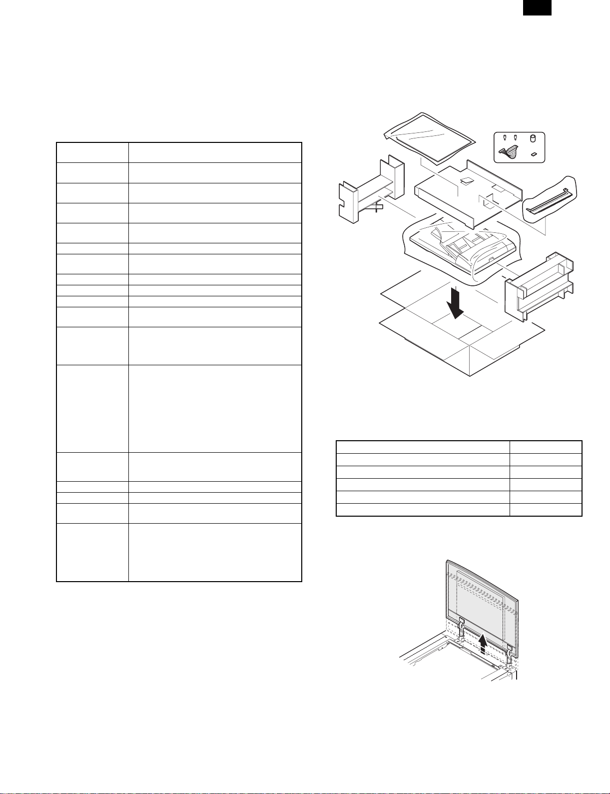
1. Unpacking
2. Installation
(1) Package contents
Name Quantity
Screw 2
SPF harness 1
SPF glass holding cover 1
Ring core 1
Cushion 1
* Be careful not to use the removed screws in different locations.
1) Remove the document cover.
Lift the document cover and remove it from the copier.
– 1 –
Page 3
DM-SP1
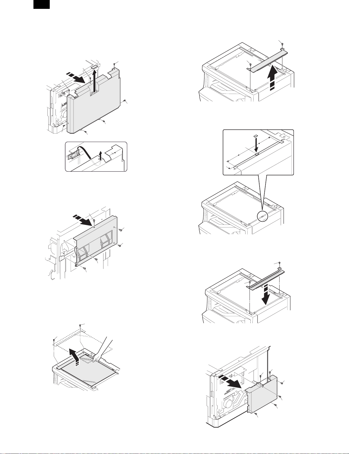
2) Remove the rear cabinet of the copier.
Remove the seven screws and remove the cabinet.
A: M3x6 for steel
B: M3x8 for steel
C: M4x 10 for plastic
A
A
B
C
A
C
C
* If a open/close detection is attached, be careful not to break the
actuator.
3) Remove the right cabinet.
Remove the five screws.
5) Remove the document glass holder cover (right side).
Remove the two screws.
A
A
6) Attach the cushion (one position).
Remove the cover of the double-sided adhesive tape and paste the
cushion taking care not to allow it to extend over the plate edges.
A
B
B
B
B
4) Remove the document glass holder (left side) and the
document glass.
Remove the two screws and carefully remove the document glass
holder (left side) and the document glass.
Do not separate the glass and holder.
A
A
7) Attach the SPF glass holder cover.
After attaching the SPF glass holding cover, attach the document
glass.
A
A
8) Remove the PWB shield plate.
Remove the six screws.
A
A
A
– 2 –
A
A
A
Page 4
DM-SP1
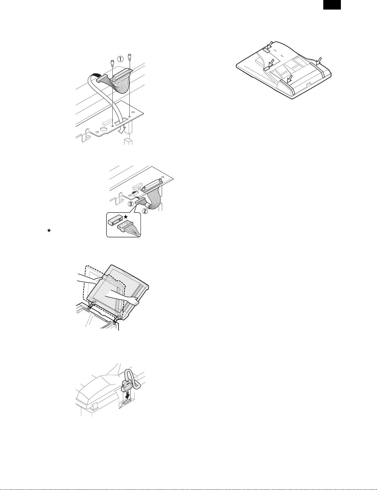
9) Install the SPF harness and the ring core
(included together with the unit).
Pass the SPF harness through the plate hole from the above and fix it
to the plate with the supplied two hex cap screws. (➀)
Pass the SPF harness through the ring core (➁), and connect it to the
main PWB connector (CN11) inside the copier. (➂)
Be careful about the direction
of the connector.
10) Install the SPF to the copier.
Tilt the SPF backward and insert the hinges into the hinge guides.
12) Remove the filament tape.
Remove the filament tape at four positions.
Connect the power cord, turn the main switch ON, and
perform the following procedure.
13) Check the magnification ratio.
• Place a document on the document glass and make a copy.
Then, place a document in the automatic document feeder tray
and make a copy.
• If the copy magnification ratio of the copy made with the automatic
document feeder is different than that of the copy image made with
the document glass,perform the magnification adjustment according to the procedure in the service manual.
14) Check the center displacement.
• Place a document on the document glass and make a copy.
Then, place a document in the automatic document feeder tray
and make a copy.
• If the center of the copy from the automatic document feeder is
displaced from the copy from the document glass, adjust the center according to the procedure in the service manual.
15) Check the leading edge margin.
• Place a document on the document glass and make a copy.
Then, place a document in the automatic document feeder tray
and make a copy.
• If the leading edge margin of the copy from the automatic docu-
ment feeder is displaced from the copy from the document glass,
adjust the margin according to the procedure in the service
manual.
16) Check the open/close detection position.
(only models with original size detection)
• If the open/close detection position measured by the open/close
detection position adjustment method in the service manual is outside the specified values, adjust the position in accordance with
the manual.
11) Install the interface harness.
Connect the interface harness from the SPF to the machine and
tighten the screws.
– 3 –
Page 5
DM-SP1
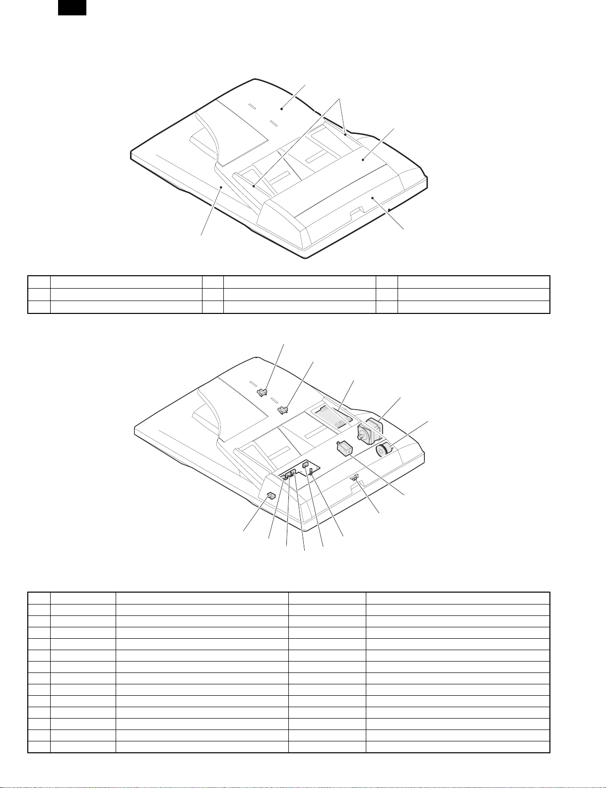
[4] EXTERNAL VIEW AND INTERNAL STRUCTURE
1. External view
1
2
3
4
5
No. Name No. Name No. Name
1 Document set tray 2 Document guide 3 Document feed section cover
4 Document transport section cover 5 Document exit section
2. Internal structure
14
13
12
10
9
6
7
Sensors and detectors
No. Code Name Type Function, operation
1 W0 Document set sensor Photo transmission Document presence detection
2 COVER Open/close sensor Photo transmission Paper feed unit open/close detection
3 W1 Document sensor (A4R, LTR, A5) Photo transmission Tray document width detection
4 W2 Document width sensor (B4R, B5) Photo transmission Tray document width detection
5 W3 Document width sensor (WLTR, A5R, A4, LT) Photo transmission Tray document width detection
6 PSOL Pickup solenoid — —
7 PAPER Paper entry sensor Photo transmission Document presence detection
9 CLH Transport clutch — —
10 MOT SPF motor Stepping motor Tray paper feed, transport, paper exit roller drive
12 — Interface PWB — —
13 L1 Document length detection SW (Short) Photo transmission Tray document length detection
14 L2 Document length detection SW (Long) Photo transmission Tray document length detection
15 COVER OPEN Book sensor Photo transmission Detects SPF floating.
15
5
4
3
2
1
– 4 –
Page 6
DM-SP1
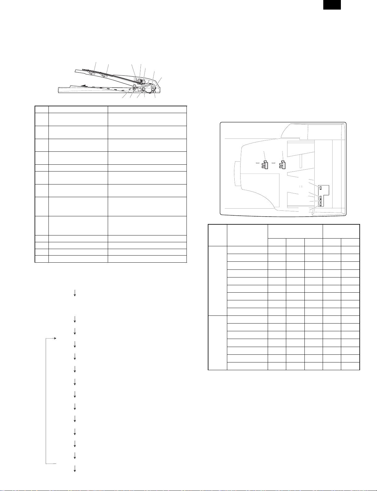
[5] OPERATIONAL DESCRIPTION
1. Paper feed section major parts
1
2
13
No. Part name Operation
1 Document length
sensor (L2)
2 Document length
sensor (L1)
3 Document length
sensor (W0)
4 Document width sensor
(W1, W2, W3)
5 Pickup roller Picks up the document.
6 Paper feed roller Feed and transport the
7 Paper entry sensor
(PAPER)
8 PS roller Makes synchronization between
9 PS follower roller Makes synchronization between
10 Transport roller Transports the document.
11 Transport follower roller Transports the document.
12 Paper exit follower roller Discharges the document.
13 Paper exit roller Discharges the document.
Detects the document length on
the tray.
Detects the document length on
the tray.
Detects the presence of
document.
Detects the document width.
document.
Detects the document transport.
the document lead edge and the
image lead edge.
the document lead edge and the
image lead edge.
2. Brief descriptions of operations
1) Document set (Document set sensor ON)
2) Document size detection (The document width is detected
with document width sensors W1, W2, and W3, and the
document length is detected with document length sensors
L1 and L2.)
3) Copy start (Machine)
4) SPF motor ON
5) Pickup solenoid ON
6) Pickup roller rotation
7) Paper feed roller rotation
12
3,4
5
6
7
8
1011
9
3. Document size detection
Document size detection by document set tray
When a document is set on the document set tray in the auto mode of
paper/copy magnification ratio selection, the document size is
detected to perform the auto selection function of paper and the copy
magnification ratio according to the detected document size.
When documents of different sizes are mixed and set on the tray, the
max. size is detected. The document width is detected by the document width sensors (W1, W2, W3), and the document length is
detected by the document length sensors (L1, L2) to determine the
document size.
The document size judgment is made after a certain time from when
the document set sensor (W0) detects the document.
L2 L1
W0
W1
W2
W3
Document size
and set direction
A5 FDDDD
B5 FFDDD
A5R DDDDD
A4 FFFDD
AB
series
B5R DDDFD
A4R FDDFD
8.5" × 13" FDDFF
B4 FDDFF
A3 FFFFF
8.5" × 5.5" FDDDD
8.5" × 5.5"R DDDDD
11" × 8.5" FFFDD
Inch
11" × 8.5"R FDDFD
series
8.5" × 13" FDDFF
8.5" × 14" FDDFF
11" × 17" FFFFF
[Note] Sensor ON: F OFF: D
Document width
sensor
W1 W2 W3 L1 L2
Document
length sensor
8) Paper entry sensor detects paper presence.
9) PS roller rotation
10) Copy operation (Machine)
11) Transport roller rotation
12) Paper exit roller rotation
13) Document exit
YES
14) Next document
15) SPF motor OFF
NO
– 5 –
Page 7

DM-SP1
[6] DISASSEMBLY AND ASSEMBLY
1. External fitting section
NOTE: Remove the pawl in the arrow direction.
2
2
1
2) Document transport section cover
1
2
1
3) Document feed section cover
2
2
3
2. Paper feed unit section
1) Paper feed unit
1
1
4) Sensor PWB
2
1
1
4
2
3
3
1
1
– 6 –
Page 8

DM-SP1
5) Pickup solenoid
NOTE: Remove section A of the pickup solenoid from the solenoid
arm groove.
2
1
A
7) Pickup roller ass’y
NOTE: When setting the pickup roller ass’y 4, check that rib A is on
the solenoid arm rib.
A
1
2
4
6) Clutch gear ass’y
5
3
6
6
1
8) Pickup roller, paper feed roller
4
3
3
1
2
1
4
2
1
– 7 –
Page 9

DM-SP1
3. Interface PWB
2
2) Rack cover
1
2
3) Document length detection SW
2
1
1
2
1
1
4. Document tray section
1) Document tray
2
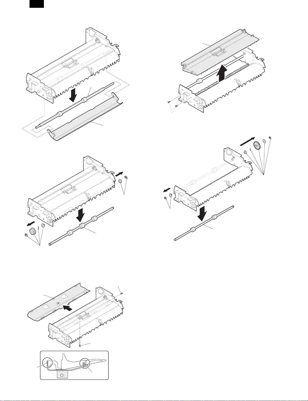
5. Drive frame section
1) Drive frame unit
3
1
1
2
1
1
– 8 –
1
Page 10

DM-SP1
2) Transport belt
1
3) Drive frame ass’y and drive belt
2
6. Transport section
1) Clutch
NOTE: When assembling, check that the rib is in the clutch groove
A, and fix the E-ring.
3
A
1
1
4) SPF motor
3
2
2) Transport roller gear
1
1
1
1
3
2
– 9 –
Page 11
DM-SP1
3) Transport roller
4) PS roller
6) Paper feed paper guide lower
2
1
1
1
7) Paper exit roller
1
2
1
5) Paper feed paper guide upper
NOTE: When assembling, check that the paper feed paper guide
upper is set to rib A and boss B.
1
2
1
1
2
B
3
A
– 10 –
Page 12

[7] MAINTENANCE
1. Maintenance parts
DM-SP1
No. Name Work item
(1) Pickup roller Cleaning F
(2) Separation pad Cleaning F
(3) Paper feed roller Cleaning F
(4) PS roller Cleaning F
(5) Transport roller Cleaning F
(6) Paper exit roller Cleaning F
When
service call
1
Remark
3
2
6
5
4
[Note] When performing maintenance, refer to [6] DISASSEMBLY
AND ASSEMBLY.
– 11 –
Page 13

DM-SP1
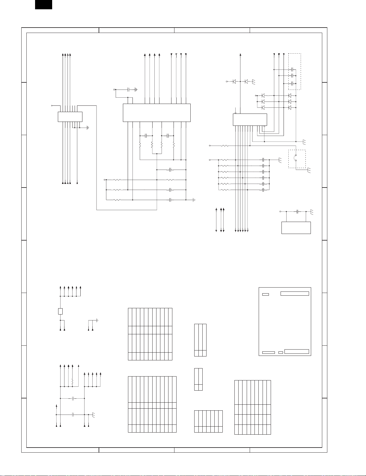
[8] ELECTRICAL SECTION
D
C
B
A
1/1
12345678
SPF/RSPF UNIT
2 1
3
B/
COVER OPEN
5V2
PAPER
COVER
5V2
W1
W0L1W2
Senser PWB
W3
5V2
L2
SENSER
5V2
24V
24V
24V
CLH
RSOL
PSOL
RSPF ONLY
24V
GSOL
SOL./CLU.
RSPF ONLY
24V
MOT
AA/B
4
24V
24V
5V2
5V1
Data selector
5V1
PAPER
COVER
IC001
3
Y
24V
Driver array
IC003
5
SELA
SELB
SELB
CLH
RSOL
PSOL
PDOWN
INTERFACE PWB
Motor driver
IC002
4
MOTA
MOTB
MOTBN
GSOL
PDOWN
MOTAN
Copier body
1. BLOCK DIAGRAM
D
8 7 6 5 4
C
B
A
– 12 –
Page 14

DM-SP1
D
C
B
A
12345678
L2
L1
1
OR
2
L1
5
3
2
1
5V
6
PHNR-6-H
Original Tray
DF3-3S-2C
PHNR-6-H
RSOL
CLH
PAPER
1
2
3
PHR-3
SMR-02V(B)
SMR-02V(N)
CLH/
24V1
1
RSOL/
24V1
2
2
1
GSOL
RSPF ONLY
2 1
3
MOT
SMP-02V(N)
SMP-02V(B)
4
PHR-6
5
1
2
3
6
Senser PWB
(PHR-7)
PAPER FEED UNIT
CN101
OR
BU7P-TR-P-H
COVER
5V
W1
W0
3
1
2
6
1W0
6
3
25V
W1
COVER
7
6
2
5
PSOL
W3
LGND
W2
5
4W2
7
GY
5
2
7
4
PHNR-7-H
LGND
W3
W2
4
24V1
1
1
3
BU2P-TR-P-H
PHNR-7-H
1
3
2
DF3-3S-2C
LB
BL
GY
OR
GY
1
PHNR-2-H
PSOL/
2
PHNR-2-H
3
5
4
6
LGND
L2
5V
LGND
1
2
4
3
BU6P-TR-P-H
2. ACTUAL WIRING DIAGRAM 1/1
OR
1
5V2
(PHDR-22VS)
CN002
Interface PWB
24V
(PHDR-24VS)
CN001
22
RD
24V
1
CL211-0211-6
PPC
RD
LB
12
24V1
FG
6
CLH/
RD
14
24V1
RD
PK
PL
1
8
RSOL/
EARTH
2
24V1
GSOL/
(PHR-2)
CN004
PLATE
PLATE
SPF FIXING
CN003
CN005
PGND
23
GY
LGND
5
GY
GY
LGND
6
LB
BL
21
LGND
PAPER
8
BL
OR
GY
LB
OR
20
15
17
3
4
5V2
L2
5V2
L1
LGND
Y
SELA
SELC
SELB
COVER OPEN
PDOWN
COVER
4
3
2
12
1
11
10
PL
BR
LB
OR
BL
BR
BR
5V1
7
GY
BR
PL
22
5
18
PAPER
LGND
LEDSPPD
5V2
9
INTERNAL SPF/DSPF
OR
LB LB
BL BL
PL PL
PK PK
BR BR
9
7
16
11
13
W1
W3
W0
COVER
CLH
PSOL
RSOL
24V
GSOL
15
24
13
17
19
PL
BR
PL
RD
PL
GY
PK
19
LGND
MOTA
18
BR
BL
RD
10
2
PSOL/
24V1
MOTB
PGND
MOTBN
MOTAN
16
20
21
14
GY
PL
BL
GY
PL
1
B
(PHR-7)
(PHR-3)
1 COVER OPEN
2
PK
2
B/
2LGND
ORBRGY
1
BL
3
A
35V2
3
LB
RD
RD
6
7
24V1
A/ 4
N.C.
24V1 5
DF3-3S-2C
COVER OPEN
GP1A71A1
MOTA
CLH
6
MOTBN
PGND
MOTB
PGND
MOTAN
9
8
7
LGND
LGND
14
11
13
10
12
Y
COVER
COVER OPEN
PAPER
PDOWN
16
15
19
18
17
5V2
5V1
SELC
SELB
SELA
23
20
22
24
21
FG
25 N.C.
SRA-21T-4
8 7 6 5 4
24V
2
GSOL
PSOL
RSOL
3
5
4
D
C
B
A
– 13 –
Page 15
DM-SP1
SELC
A
CN001-1
CN001-4
CN001-2
SELA
SELB
C017
2200pFx3
C016
C015
D002 D003
1SS133x3
D001
DSPF
C012
C010
C003
5V1
IC001
100000pF
16
8
2 1
3
74HC151AP
5V1
5V1
B
R015
R014
R013
R012
R011
R010
CN001-10
CN001-12
COVER
PAPER
COVER OPEN
CN005-1
CN002-16
D008
1SS133
5V1
6
W
IC001
D04D13D22D31D415D514D613D712A11B10C9G
R016
10kJ
CN001-8
W1
CN002-18
CN001-3
Y
D007
1SS133
1SS133x3
D006
5V1
D005
D004
5
Y
74HC151
7
C014
2200pFx6
C013C009
C011
W0(Document Size Senser)
L2
W3
CN002-11
CN002-9W2CN002-13
CN002-7
CN002-15L1CN002-17
+
7
2
C001
VSA
TdA
47uF/35V
12
VSB
TdB13RSA
C
CN003-4
CN003-2
CN001-20
CN001-14
CN003-3
CN003-1
A/
B/
B
A
11
1
8
18
OUTB
OUTA
OUTA
OUTB
REFA
9
R001
1.5J(1W)
REFB
3
14
C007
2200pF
C008
R007
2.4kJ
R006
2.4kJ
CN001-16
CN001-18
MOTAN
MOTB
MOTBN
MOTA
5
6
16
17
INA
INA
INB
INB
GA
GB
RSB
10
2200pF
R002
C004
R003
C006
C005
1.5J(1W)
0.1uF
1.5KJ
470pF
470pF
SLA7027M
4
15
D
1/1
12345678
CN002-2
CN002-6
CN002-8
CN004-2
PSOL/
CLH/
RSOL/
GSOL/
24V1
24V1
9
10
O116O215O314O413O512O611O7
COM
IC003
PSOL
I11I22I33I44I55I66I7
CLH
RSOL
GSOL
CN001-19
CN001-17
CN001-15
CN001-13
GND
8
7
PDOWN
CN001-11
BA12003B
5V1
IC002
9.1KJ
R005
47kJ
R009
47kJ
R008
CN002-10
CN002-12
CN002-14
CN003-5
CN003-6
CN004-1
24V1
ICP001
ICP-N38
24V
24V
CN001-24
CN001-22
CN002-1
CN002-3
TO 5V1
5V1
5V2
PGND
PGND
CN001-21
CN001-23
CN002-4
CN002-5
CN005-3
CN002-19
CN002-20
CN002-21
CN002-22
CN005-2
LEDSPPD
220J(1/4W)
LED POWER
LGND
R004
C018
10uF/16V
+
C002
10uF/16V
+
LGND
LGND
1. INTERFACE PWB
3. CIRCUIT DIAGRAM
CN001-7
CN001-9
CN001-5
CN001-6
D
(PHDR-22VS)
CN002
(PHDR-24VS)
CN001
PSOL/
5V2
CLH/
RSOL/
246
8
5V2
LEDSPPDW0W2W3W1L1L2
5V2
13579
SELB
SELC
LGND
PAPER
SELAYLGND
5V1
123456789
C
24V1
24V1
24V1
COVER
PAPER
LGND
10121416182022
LGND
1113151721
19
COVER
MOTB
MOTBN
MOTA
MOTAN
COVER OPEN
10
12141618202224
CLH
5V2
PSOL
PDOWN
GSOL
RSOL
11131517192123
LGND
LGND
24V
PGND
24V
PGND
COVER OPEN
1
(PHR-3)
CN005
24V1
1
(PHR-2)
CN004
BB/AA/24V1
12345
(PHR-6)
CN003
CN001
CN005
(PHR-3)
LGND
LED POWER
3
2
CN003
(PHR-7)
GSOL/
2
W1W2W3
W0
L1
L2
SPF/ /RSPF
L
HL
LH
L
L
HH
LLL
H
LLH
HHH
HH
H
SELA
LL
24V1
6
SELB
7N.C.
L
SELC Y
MATRIX
Senser
B
(PHDR-24VS)
PARTS VIEW
CN002
CN004
(PHR-2)
(PHDR-22VS)
8 7 6 5 4
A
– 14 –
Page 16

DM-SP1
D
C
B
A
1/1
12345678
CN101-5
GP1S58V
PT105
W3
R103
240J/ 1/4W
CN101-3
W1
PT103
GP1S58V
W2
CN101-4
PT104
GP1S58V
2 1
3
R102
120J/ 1/4W
CN101-1
PT101
W0
R101
120J/ 1/4W
5V
CN102-2
CN101-6
GP1S58V
C101
22000pF
COVER
PT102
GP1S58V
SGND
CN101-7
W05VW1W2W3
(PHR-7)
1234567
CN101
2. SENSOR PWB
D
COVER
SGND
8 7 6 5 4
C
B
– 15 –
A
Page 17

DM-SP1
4. PARTS ARRANGEMENT
[PARTS SURFACE]
PSOL/
5V2
CLH/
RSOL/
24V1
24V1
24V1
COVER
PAPER
LGND
LGND
2
4
6
8
10
12
14
16
18
20
(PHDR-22VS)
CN002
22
LGND
21
LGND
19
5V2
LEDSPPD
W0
W2
W3
W1
L1
L2
3
5
7
9
11
13
15
17
5V2
1
(PHR-2)
CN004
GSOL/
2
24V1
1
N.C.
7
24V1
6
(PHR-6)
CN003
24V1
5
B
B/
A
A/
1
2
3
4
[SOLDER SURFACE]
(PHDR-24VS)
CN001
123456789
SELAYLGND
5V1
SELB
SELC
LGND
PAPER
11131517192123
5V2
10
COVER
CLH
PDOWN
GSOL
RSOL
12141618202224
MOTB
MOTBN
MOTA
COVER OPEN
PSOL
MOTAN
PGND
24V
PGND
24V
(PHR-3)
CN005
1
2
3
LED POWER
LGND
COVER OPEN
– 16 –
Page 18

DM-SP1
q
COPYRIGHT C 1999 BY SHARP CORPORATION
All rights reserved.
Printed in Japan.
No part of this publication may be reproduced,
stored in a retrieval system, or transmitted,
in any form or by any means,
electronic, mechanical, photocopying, recording, or otherwise,
without prior written permission of the publisher.
SHARP CORPORATION
Digital Document Systems Group
Quality & Reliability Control Center
Yamatokoriyama, Nara 639-1186, Japan
1999 June Printed in Japan K
 Loading...