

Page 1
CODE: 00ZDMDE2//A1E
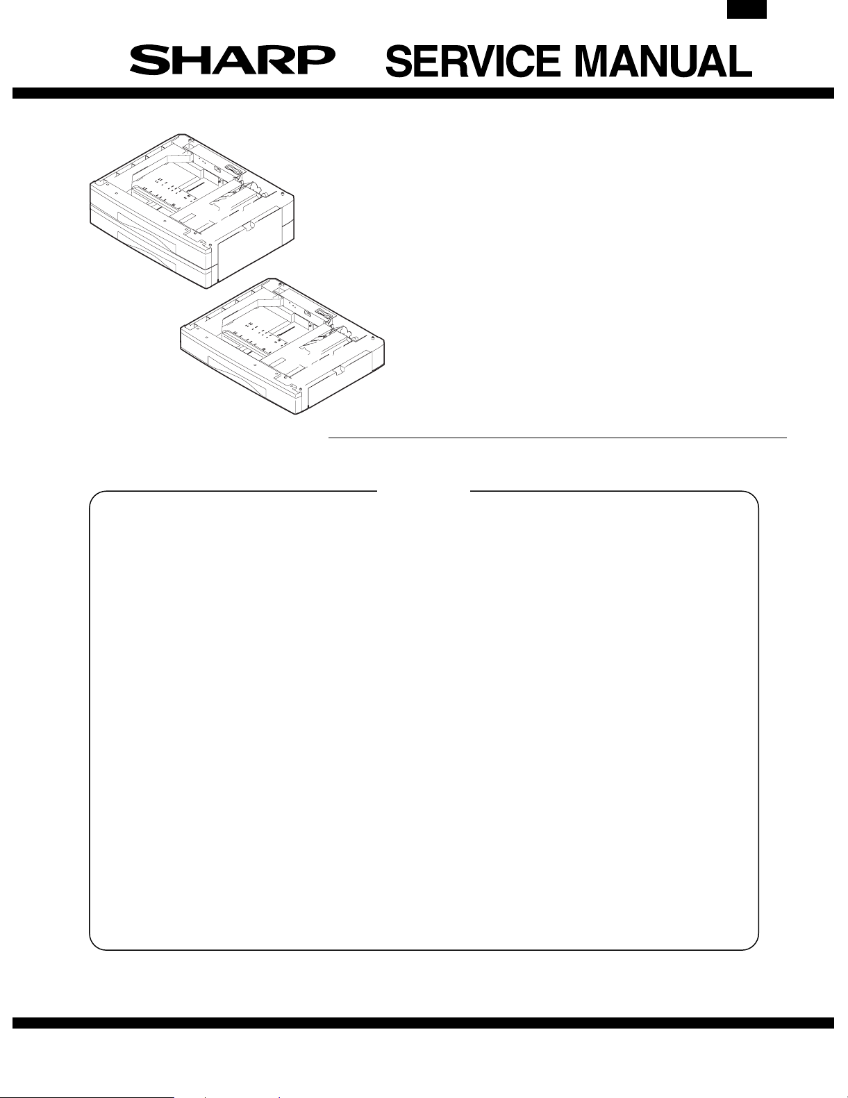
Digital copier
: Paper feed unit
DM-DE1
MODEL DM-DE2
250-sheet paper
feed unit
500-sheet paper
feed unit
DM-DE2
CONTENTS
[1] PRODUCT OUTLINE . . . . . . . . . . . . . . . . . . . . . . . . . . . . . . . . . . . . 1
[2] SPECIFICATIONS . . . . . . . . . . . . . . . . . . . . . . . . . . . . . . . . . . . . . . 1
[3] UNPACKING AND INSTALLATION . . . . . . . . . . . . . . . . . . . . . . . . . 1
[4] EXTERNAL VIEW AND INTERNAL STRUCTURE . . . . . . . . . . . . . 6
[5] OPERATIONAL DESCRIPTION . . . . . . . . . . . . . . . . . . . . . . . . . . . . 7
[6] DISASSEMBLY AND ASSEMBLY . . . . . . . . . . . . . . . . . . . . . . . . . . 7
[7] MAINTENANCE . . . . . . . . . . . . . . . . . . . . . . . . . . . . . . . . . . . . . . . . 9
[8] ELECTRICAL SECTION . . . . . . . . . . . . . . . . . . . . . . . . . . . . . . . . . 10
Parts marked with "!" are important for maintaining the safety of the set. Be sure to replace these parts with specified
ones for maintaining the safety and performance of the set.
This document has been published to be used
SHARP CORPORATION
for after sales service only.
The contents are subject to change without notice.
Page 2
DM-DE2
[1] PRODUCT OUTLINE
The 250-sheet paper feed unit and the 500-sheet paper feed unit are
the optional paper feed cassettes for the digital copier, and they are
the same structure as the 250-sheet cassette of the copier.
The combination of the copier and the paper feed cassette is as
shown below:
Copier
(2-Tray Model)
Standard cassette
Standard cassette
250-sheet paper feed unit
250-sheet cassette
250-sheet cassette
500-sheet paper
feed unit
[2] SPECIFICA TIONS
1. Paper feed unit
DM-DE1 DM-DE2
Paper feed step(s) 1-step 2-step
Paper feed capacity 250 sheets × 1 step 250 sheets × 2 steps
Size detection None (The paper size is set by the user
Paper feed detection Available
Paper feed size 11 × 17, 8.5 × 14, 8.5 × 13, 8.5 × 11
Paper weight 56 ∼ 80g/m2, 15 ∼ 21lbs
Shipping size Inch series: 11" × 17"
Size selection User operation (Size setting by the user
Cassette
detachment
Heater Not available
Power source Supplied from the machine.
External dimension 590 (W) × 471 (D) ×
Weight About 5 Kg About 10 Kg
program.)
8.5 × 11R
program)
11 × 17, 8.5 × 14, 8.5 × 11, 8.5 × 11R
Possible by the user
590 (W) × 471 (D) ×
88 (H) mm
173.5 (H) mm
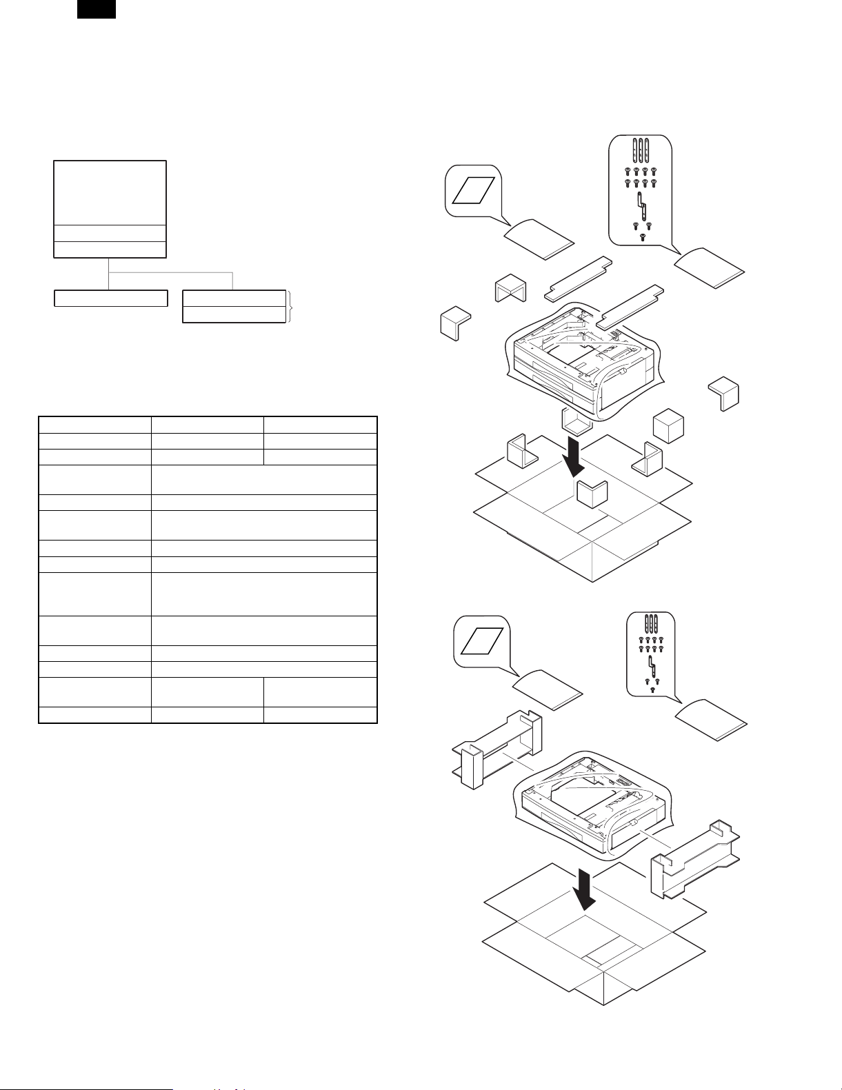
[3] UNPACKING AND INSTALLATION
1. Unpacking
(DM-DE2)
(DM-DE1)
– 1 –
Page 3
DM-DE2
2. Installation
Included parts
Part name Quantity
Screw (for plastic M4) 8
Screw (for steel M4) 2
Screw (flat-head M3) 1
Fixing plate 3
Fixing plate 1
Paper size label 1
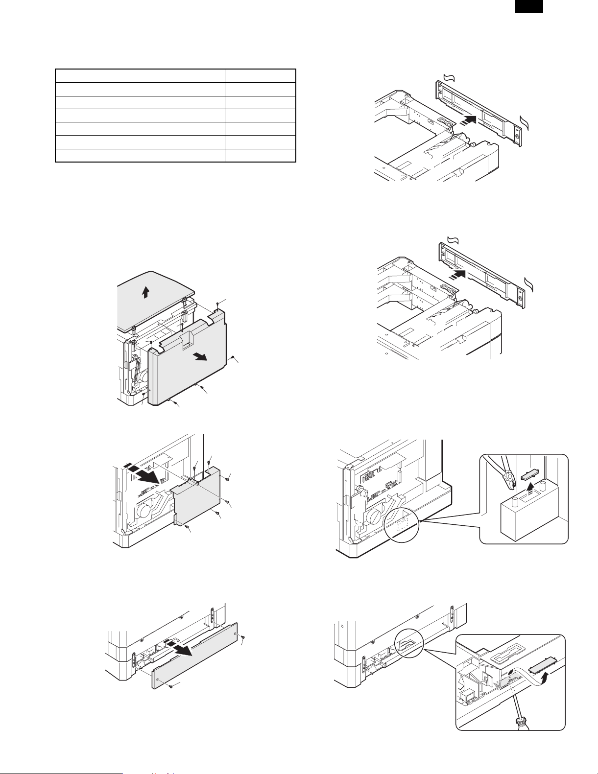
1) Remove the platen cover, rear cabinet, shielding plate
and rear cover.
DM-DE1 (Copier with 2 cassettes + Second cassette)
DM-DE2 (Copier with 2 cassettes + Multi-step cassette)
Remove the platen cover.
Remove the seven screws and then remove the rear cabinet.
A: M3 × 6 for steel
B: M3 × 8 for steel
C: M4 × 10 for plastic
A
2) Remove the rear cover.
DM-DE1 (Remove the rear cover which is attached to the second
cassette by tape.)
When installing, fix it using the two screws (for steel M4).
DM-DE2 (Remove the rear cover (upper stage) from the multi
stage cassette attached by tape.)
A
A
C
C
C
B
C
Remove the six screws.
A
A
A
A
A
A
DM-DE1 (Copier with 2 cassettes + Second cassette)
DM-DE2 (Copier with 2 cassettes + Multi-step cassette)
Remove the two screws.
D: M4 × 10 for steel
When installing, fix it using the two screws (for steel M4).
3) Remove the cut out plate in the copier base.
DM-DE1 (Copier with one cassette + Second cassette)
DM-DE2 (Copier with one cassette + Multi-step cassette)
Use nippers to cut and remove the plate.
DM-DE1 (Copier with 2 cassettes + Second cassette)
DM-DE2 (Copier with 2 cassettes + Multi-step cassette)
Use a screwdriver to assist in removing the plate.
D
D
– 2 –
Page 4
DM-DE2
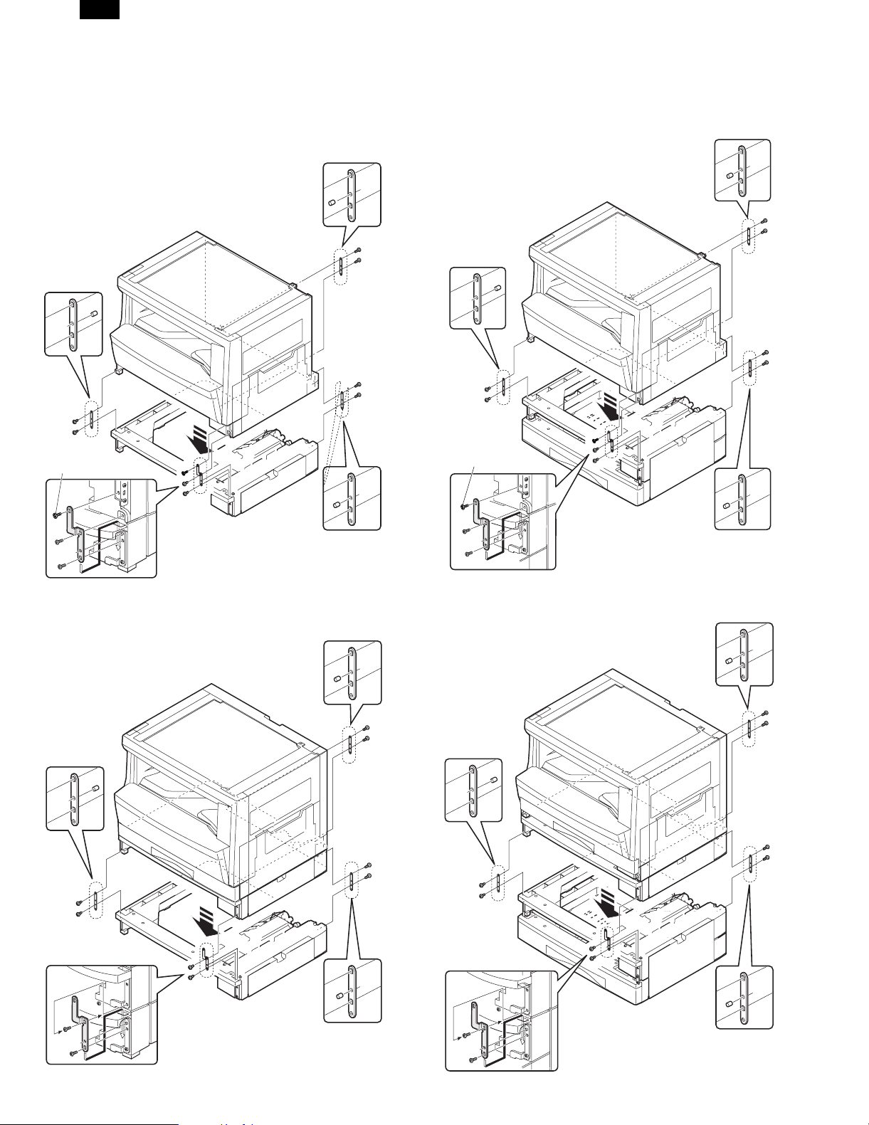
4) Install the copier.
DM-DE1 (Copier with one cassette + Second cassette)
Put the copier on the second cassette, and fix with the four fixing
plates and the eight screws (for plastic M4).
Fix it with the plate of the copier using a screw (flat-head M3).
When installing, remove the paper cassette.
Detail drawing
Detail drawing
Screw (flat-head M3)
DM-DE2 (Copier with one cassette + Multi-step cassette)
Put the copier on the multi-step cassette, and fix it with the four fixing
plates and the eight screws (for plastic M4).
Fix it with the plate of the copier using a screw (flat-head M3).
When installing, remove the first and second paper cassettes.
Detail drawing
Detail drawing
Screw (flat-head M3)
Detail drawing
DM-DE1 (Copier with 2 cassettes + Second cassette)
When installing, remove the second and third paper cassettes.
Detail drawing
Detail drawing
Detail drawing
DM-DE2 (Copier with 2 cassettes + Multi-step cassette)
When installing, remove the second and third paper cassettes.
Detail drawing
Detail drawing
Detail drawing
Detail drawing
– 3 –
Page 5
DM-DE2
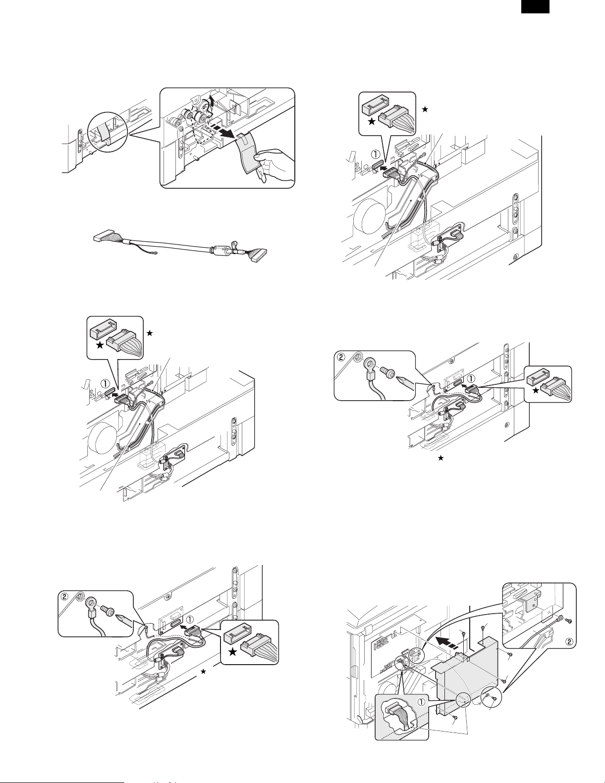
5) Remove the connection gear lock.
DM-DE1, DM-DE2
After setting, pull out and remove the red tag in the direction indicated
by the arrow and remove the connection gear lock.
6) Connect the connector.
DM-DE1 (Copier with one cassette + Second cassette)
Optional interface harness
Pass the optional interface harness that is contained in the second
cassette through the back of the resin holder taking care to keep the
harness from contact with the high voltage wires, and then connect
the connector. (➀)
Be careful about the direction of the connector.
DM-DE2 (Copier with one cassette + Multi-step cassette)
Pass the optional interface harness that is contained in the multi-step
cassette through the back of the resin holder taking care to keep the
harness from contact with the high voltage wires, and then connect
the connector. (➀)
Be careful about the direction of the connector.
High voltage wires
Harness holder
(Copier with 2 cassettes + Multi-step cassette)
Connect the optional interface harness that is contained in the multistep cassette to the connector. (➀)
Fix the terminal section of the grounding wire at the option side using
the plate fixing screw. (➁)
High voltage wires
Harness holder
(Copier with 2 cassettes + Second cassette)
Connect the optional interface harness that is contained in the second
cassette to the connector.(➀)
Fix the terminal section of the grounding wire at the option side using
the plate fixing screw. (➁)
Be careful to the front and
the back sides.
Be careful to the front
and the back sides.
Be careful about the direction of the connector.
7) Attach the shielding plate and the terminal section of
the grounding wire.
DM-DE1 (Copier with one cassette + Second cassette)
DM-DE2 (Copier with one cassette + Multi-step cassette)
When attaching the shielding plate, pass the cassette interface harness through the notch. (➀)
Use the six screws to attach the shielding plate and tighten the terminal section of the grounding wire at the location shown in the
illustration. (➁)
(Use caution to ensure no wires are pinched by the shielding plate. )
A
A
Be careful about the direction
of the connector.
A
A
A
A
Notch
– 4 –
Page 6

DM-DE2
8) Remove the cassette packing fixtures.
DM-DE1, DM-DE2
Remove the pressure plate lock. Rotate the pressure plate lock in the
direction of the arrow to remove it while pressing down the pressure
plate of the paper tray.
9) Set the cassette side plate.
DM-DE1, DM-DE2
Squeeze the lock lever of the front guide and slide the front guide to
match the width of the paper.
10) Install the cassette rear edge plate.
DM-DE1, DM-DE2
Install the cassette edge plate to the position of the paper size to be
used.
11) Set the paper.
DM-DE1, DM-DE2
When setting the paper, do not exceed the height of the indication
label.
12) Check the center displacement.
DM-DE1
• Place a document on the document glass and make a copy using
a tray in the copier.
Then, make a copy using the tray in the installed optional paper
feed unit.
• If the center of the copy from the paper feed unit is displaced from
the copy from the tray in the copier, adjust the center according to
the procedure in the service manual.
DM-DE2
• Place a document on the document glass and make a copy using
a tray in the copier.
Then, make a copy using each tray in the installed optional paper
feed unit.
• If the center of the copy from each tray of the paper feed unit is
displaced from the copy from the tray in the copier, adjust the
center according to the procedure in the service manual.
Connect the power cord, turn the main switch ON, and
perform the following procedure.
– 5 –
Page 7

[4] EXTERNAL VIEW AND INTERNAL STRUCTURE
1. External view
3
1
No. Name No. Name No. Name
1 Paper feed tray 2 2-step paper feed right cover 3 1-step paper feed right cover
2
2. Internal structure
1
DM-DE2
11
3
2
1
6
5
4
9
10
8
Sensors and detectors
No. Code Name Type Function, operation Remark
1 DRS1 Door open/close sensor Photo transmission Detects door open/close.
2 PPD1 Paper entry sensor Photo transmission Detects paper transport.
3 CSS1 Paper empty sensor Photo transmission Detects paper presence/empty.
4 CASS1 Cassette detection SW Contact Detects cassette installation.
5 FSOL1 Transport solenoid DC solenoid Transports paper. (for clutch)
6 PSOL1 Paper feed solenoid DC solenoid Feeds paper. (For clutch)
7 PPD2 Paper entry sensor Photo transmission Detects paper transport. DM-DE2 only
8 CSS2 Paper empty sensor Photo transmission Detects paper in the cassette. DM-DE2 only
9 CASS2 Cassette detection SW Contact Detects cassette installation. DM-DE2 only
10 PSOL2 Paper feed solenoid DC solenoid Feeds paper. DM-DE2 only
11 PWB Interface PWB — — DM-DE2 only
7
– 6 –
Page 8

DM-DE2
[5] OPERATIONAL DESCRIPTION
1. Paper transport path
Transport roller
PF sensor
Copier
cassette
250-sheet paper
feed unit (upper)
250-sheet paper
feed unit (Lower)
2. Operational descriptions
The operations are controlled by the main body of the copier. the
paper feed roller (semi-circular roller) and the transport roller are
driven by the gear of the copier.
Paper is separated by the paper feed roller and the separation pawl,
and detected by the PF sensor, then transported to the Resist roller
by the transport roller.
Paper feed roller
To copier's PS
[6] DISASSEMBLY AND ASSEMBLY
1. Rear cover
1
2
1
2. Paper feed unit section
5
5
Copier
4
3
1
2
250-sheet paper feed unit
Paper lead edge
No. Name Operation
1 Paper feed roller Picks up paper.
2 Separation pawl Prevents against double feed of
paper.
3 Transport roller Transports paper.
4 Paper entry sensor Detects paper transport.
5 Resist roller Makes synchronization between the
paper lead edge and the image lead
edge.
1
1
6
3
2
6
3
– 7 –
4
Page 9
DM-DE2
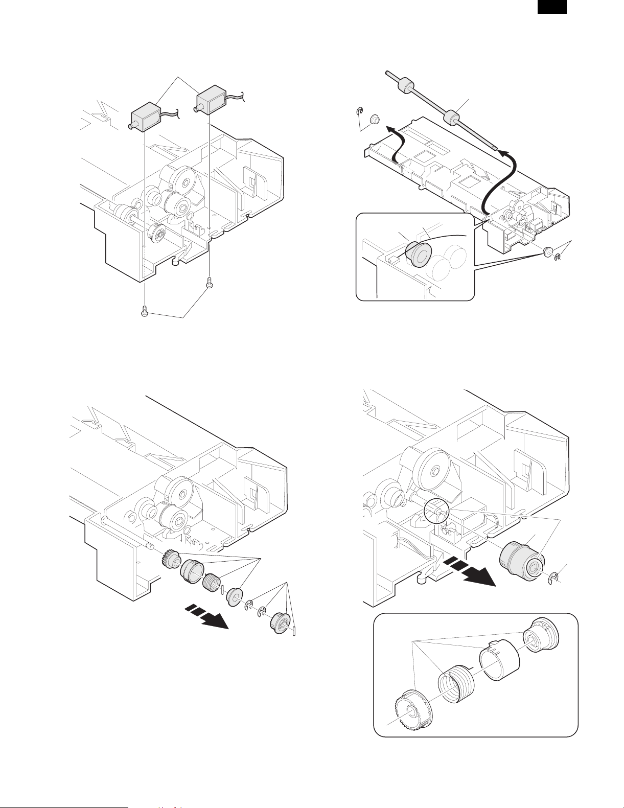
3. Paper feed solenoid, transport solenoid
2
1
4. Transport roller gear section
5. Transport roller
2
1
A
B
1
6. Paper feed roller clutch
NOTE: When asembling the paper feed roller cluch, fit and insert
section A (D cut) into the shaft as shown in the figure.
A
2
2
1
1
3
– 8 –
Page 10

DM-DE2
7. Paper feed roller
NOTE: Engage connection arm spring B with frame groove A and
connection arm groove C.
A
1
B
2
C
1
[7] MAINTENANCE
No. Name Work
item
1 Paper feed roller PA ass’y Cleaning F
2 Transport roller Cleaning F
2
[Note] For disassembly and assembly of the paper feed roller and
the transport roller, refer to [6] DISASSEMBLY AND ASSEMBLY.
When
service call
1
Remark
– 9 –
Page 11

[8] ELECTRICAL SECTION
DM-DE2
D
C
B
A
12345678
2 1
5V2
5V2
24V
5V2
24V
5V2
5V2
2nd/Multi step CS only
24V
Lower connection CS
CASS1
PPD1
DRS1
CSS1
PSOL1
FSOL1
PSOL2
CASS2
PPD2
Multi step CS only
CSS2
3
24V
5V2
5V1
5V1
IC1
Y1
Copier body
24V
Data selector
3
SELA
SELB
SELB
IC2
Driver array
PSOL1
FSOL1
PSOL2
5V1
IC3
Data selector
Y2
INTERFACE PWB
FSOL2
PSOL3
Y3
FSOL3
1. BLOCK DIAGRAM 1/1
8 7 6 5 4
D
C
B
– 10 –
A
Page 12

DM-DE2
D
2. ACTUAL WIRING DIAGRAM
12345678
1. 2nd CS TYPE DM-DE1
175778-2
1
CASS1
LGND
LGND
PPD1
5V2
LGND
DRS1
5V2
LGND
CSS1
2
1
2
3
1
2
3
1
2
35V2
GY
DF3-3S-2C
GY
OR
DF3-3S-2C
GY
OR
DF3-3S-2C
GY
OR
RD
BL
RD
BL
1
24V1
2
/PSOL1
1
24V1
2
/FSOL1
CASS1
PPD1
DRS1
CSS1
PSOL1
FSOL1
SELB
18
SELB
SELB
18415
19
SELC
SELC
19
A
5V2
5V120SELC
2 1
5V1
5V2
N.C.
N.C.
3
5V2
5V1
20
C
BR
GY
BR
OR
PL
LB
SMP-02V-NCSMR-02V-N
1
2
SMP-02V-BCSMR-02V-B
1
2
RD
BL
RD
BL
B
PHDR-20VS
TO 2ND OR MAIN BODY
(UPPER UN)
PGND
PSOL2Y1LGND
FSOL1
PSOL39FSOL37Y3
FSOL2
24VY224V
PSOL1
2
3
1
RDRDPK
123 4 56789
CASS1
13
LGND
9
16
11
14
15
PPD1
5V2
DRS1
CSS1
24V
24V
CN-B
(B16B-PHDSS)
10 16814
5
46
PK
GYGYGYBRPLPLPLOROR
PKPKPK
PK
21 22
PSOL1
FSOL1
FSOL2
PSOL2
PSOL3
PGND
FSOL3
CS INTERFACE PWB
2ND CS
1
24V1
/PSOL1
2
3
24V1
4
/FSOL1
5
N.C.
N.C.
6
N.C.
7
N.C.
8
N.C.
10
N.C.
12
CN-C
24V
24V
FSOL3
FSOL2
PSOL2
N.C.
PSOL3
2
1
N.C.
10 16
8
5
3
9
7
6
SELA
PGND
LGND
13
12
17
11
15
BR
GY
BR
1011 12 13 1415 1617 1819 20
PGND
LGND
LGND
Y3Y2Y1
SELA
CN-A
(B22B-PHDSS)
(B20B-PHDSS)
Y3
Y2
LGND
LGND
PGND13PGND
N.C.
SELA
14
12
17
11
ELP-02V
1
AC100N
AC100L
2
FOR LOWER OPTION CS
ELR-02V
AC100N
AC100L
D
TO 2ND OR MAIN BODY
(UPPER UN)
WH
1
BK
2
ELP-02V
WH
BK
1
2
AC100N
C
ELR-02V
1
2AC100L
2nd CS UNIT
PPD1
DRS1
FSOL1
CASS1
HEATER DH1
JAPAN ONLY
PSOL1
CSS1
UNIT REAR VIEW
PWB
8 7 6 5 4
B
A
– 11 –
Page 13

DM-DE2
D
2. MULTI CS TYPE DM-DE2
12345678
UPPER UNIT
175778-2
1
CASS1
LGND
LGND
PPD1
LGND
DRS1
LGND
CSS1
CASS2
LGND
LGND
PPD2
5V2 3
GY
2
DF3-3S-2C
GY
1
2
OR
35V2
DF3-3S-2C
GY
1
2
OR
35V2
DF3-3S-2C
GY
1
2
OR
35V2
RD
BL
RD
BL
175778-2
1
2
DF3-3S-2C
GY
1
2
OR
CASS1
PPD1
DRS1
CSS1
PSOL1
FSOL1
LOWER UNIT
CASS2
PPD2
SELA
17
SELA
SELB
18
SELB
19
SELC
5V120SELC
5V1
5V2
5V2
A
2 1
N.C.
N.C.
3
C
BR
GY
BR
OR
PL
LB
1
2
1
2
SMP-02V-NCSMR-02V-N
1
24V1
2
/PSOL1
SMP-02V-BCSMR-02V-B
1
24V1
2
/FSOL1
SMR-08V-N SMP-08V-NC
BR
GY
GY
BR
OR
CASS2
1
1
LGND
2
2
LGND
3
3
PPD2
4
4
5V2
5
5
RD
BL
RD
BL
BR
BR
B
PHDR-20VS
TO 2ND OR MAIN BODY
(UPPER UN)
24VY224V
2
3
1
RDRDPK
123 4 56789
CASS1
13
9
LGND
24V
24V
16
PPD1
5V2
11
14
15
12
10
1
2
3
4
8
5
6
7
DRS1
CSS1
24V1
/PSOL1
24V1
/FSOL1
CASS2
PPD2
CSS2
24V1
/PSOL2
N.C.
CN-B
(B16B-PHDSS)
PGND
PSOL2Y1LGND
FSOL1
PGND
LGND
PSOL39FSOL37Y3
FSOL2
PSOL1
10 16814
13
12
11
5
46
PK
GYGYGYBRPLPLPLOROR
PSOL1
FSOL1
PSOL2
PKPKPK
21 22
FSOL2
PSOL3
PK
FSOL3
PGND
PGND
GY
LGND
BR
1011 12 13 1415 1617 1819 20
LGND
CN-A
(B22B-PHDSS)
CS INTERFACE PWB
MULTI CS
15
BR
Y3Y2Y1
CSS2
PSOL2
PPD1
DRS1
FSOL1
CASS1
PPD2
CASS2
1
LGND
2
CSS2
5V2
3
MULTI CS UNIT
CSS1
PSOL1
CSS2
PSOL2
DF3-3S-2C
GY
OR
RD
BL
PWB
GY
LGND
6
LB
CSS2
7
OR
5V2
8
SMR-02V-N SMP-02V-NC
RD
24V1
1
BL
/PSOL2
2
UNIT REAR VIEW
UPPER UNIT
LOWER UNIT
6
7
8
1
2
LB
RD
BL
ELP-02V
1
2
TO 2ND OR MAIN BODY
(UPPER UN)
AC100N
AC100L
ELP-02V
WH
BK
1 AC100N
AC100L
2
ELR-02V
1
2
UPPER CS
HEATER DH2
LOWER CS
1
ELP-02V
1 AC100N
AC100L 2
2
ELR-02V
HEATER DH3
JAPAN ONLY
8 7 6 5 4
D
C
B
A
– 12 –
Page 14

DM-DE2
q
COPYRIGHT C 1999 BY SHARP CORPORATION
All rights reserved.
Printed in Japan.
No part of this publication may be reproduced,
stored in a retrieval system, or transmitted,
in any form or by any means,
electronic, mechanical, photocopying, recording, or otherwise,
without prior written permission of the publisher.
SHARP CORPORATION
Digital Document Systems Group
Quality & Reliability Control Center
Yamatokoriyama, Nara 639-1186, Japan
1999 June Printed in Japan K
 Loading...