

Page 1

LASER PRINTER
Operation Manual (for copier)
Be sure to become thoroughly familiar with this manual to gain
the maximum benefit from the product.
Before installing this product, be sure to read the installation
requirements and cautions sections of the "Operation manual for
printer operation and general information".
Be sure to keep all operation manuals handy for reference
including this manual, the "Operation manual for printer
operation and general information" and operation manuals for
any optional equipment which has been installed.
Page 2

Page 3

INTRODUCTION
This manual describes only copier features. For operation procedures relating to both the basic printer and copier
features, refer to the “Operation manual (for printer operation and general information)”. General information required for
loading paper, adding toner, misfeed removal, and operation of peripheral devices are described in that manual.
Separate manuals are provided for the operation of network scanning and facsimile functions. Refer to the “Operation
manual (for scanner)” and “Operation manual (for facsimile )” for these descriptions.
1
Page 4

CONTENTS
Page
INTRODUCTION . . . . . . . . . . . . . . . . . . . . . . . . . . . . . . . . . . . . . . . . 1
CONTENTS . . . . . . . . . . . . . . . . . . . . . . . . . . . . . . . . . . . . . . . . . . . . 2
PART NAMES AND FUNCTIONS (B/W scanner module/DSPF) . . . . 3
● Exterior . . . . . . . . . . . . . . . . . . . . . . . . . . . . . . . . . . . . . . . . . . . . 3
● Operation Panel . . . . . . . . . . . . . . . . . . . . . . . . . . . . . . . . . . . . . . 4
● Touch Panel (basic screen of copy mode) . . . . . . . . . . . . . . . . . . 5
AUTOMATIC DOCUMENT FEEDER . . . . . . . . . . . . . . . . . . . . . . . . . 6
● Acceptable originals . . . . . . . . . . . . . . . . . . . . . . . . . . . . . . . . . . 6
SETTING ORIGINALS . . . . . . . . . . . . . . . . . . . . . . . . . . . . . . . . . . . . 7
NORMAL COPYING . . . . . . . . . . . . . . . . . . . . . . . . . . . . . . . . . . . . . 9
● Copying from the automatic document feeder . . . . . . . . . . . . . . . 9
● Automatic two-sided copying from the automatic
document feeder . . . . . . . . . . . . . . . . . . . . . . . . . . . . . . . . . . . . 11
● Copying from the document glass . . . . . . . . . . . . . . . . . . . . . . . 12
● Automatic two-sided copying from the document glass . . . . . . . 14
EXPOSURE ADJUSTMENTS . . . . . . . . . . . . . . . . . . . . . . . . . . . . . 15
REDUCTION/ENLARGEMENT/ZOOM . . . . . . . . . . . . . . . . . . . . . . . 16
● Automatic selection (auto image) . . . . . . . . . . . . . . . . . . . . . . . 16
● Manual selection . . . . . . . . . . . . . . . . . . . . . . . . . . . . . . . . . . . . 17
SPECIAL PAPERS . . . . . . . . . . . . . . . . . . . . . . . . . . . . . . . . . . . . . 18
SPECIAL MODES . . . . . . . . . . . . . . . . . . . . . . . . . . . . . . . . . . . . . . 19
● Common operation procedure for using the special functions . . 19
● Margin shift . . . . . . . . . . . . . . . . . . . . . . . . . . . . . . . . . . . . . . . . 20
● Erase . . . . . . . . . . . . . . . . . . . . . . . . . . . . . . . . . . . . . . . . . . . . 21
● Dual page copy . . . . . . . . . . . . . . . . . . . . . . . . . . . . . . . . . . . . . 22
● Pamphlet copy. . . . . . . . . . . . . . . . . . . . . . . . . . . . . . . . . . . . . . 23
● Job build . . . . . . . . . . . . . . . . . . . . . . . . . . . . . . . . . . . . . . . . . . 24
● Multi shot . . . . . . . . . . . . . . . . . . . . . . . . . . . . . . . . . . . . . . . . . 25
JOB PROGRAM MEMORY . . . . . . . . . . . . . . . . . . . . . . . . . . . . . . . 26
● Storing a job program . . . . . . . . . . . . . . . . . . . . . . . . . . . . . . . . 26
● Recalling a job program . . . . . . . . . . . . . . . . . . . . . . . . . . . . . . . 27
● Deleting a stored job program . . . . . . . . . . . . . . . . . . . . . . . . . . 27
INTERRUPTING A PRINT OR COPY RUN . . . . . . . . . . . . . . . . . . . 28
MISFEED REMOVAL . . . . . . . . . . . . . . . . . . . . . . . . . . . . . . . . . . . . 29
● Misfeed in the scanner module . . . . . . . . . . . . . . . . . . . . . . . . . 29
TROUBLESHOOTING . . . . . . . . . . . . . . . . . . . . . . . . . . . . . . . . . . . 30
SPECIFICATIONS . . . . . . . . . . . . . . . . . . . . . . . . . . . . . . . . . . . . . . 31
● Copier . . . . . . . . . . . . . . . . . . . . . . . . . . . . . . . . . . . . . . . . . . . . 31
● Scanner module . . . . . . . . . . . . . . . . . . . . . . . . . . . . . . . . . . . . 31
KEY OPERATOR PROGRAMS . . . . . . . . . . . . . . . . . . . . . . . . . . . . 32
● Key operator program list. . . . . . . . . . . . . . . . . . . . . . . . . . . . . . 32
● Using the key operator programs . . . . . . . . . . . . . . . . . . . . . . . . 32
● Setting programs . . . . . . . . . . . . . . . . . . . . . . . . . . . . . . . . . . . . 33
2
Page 5
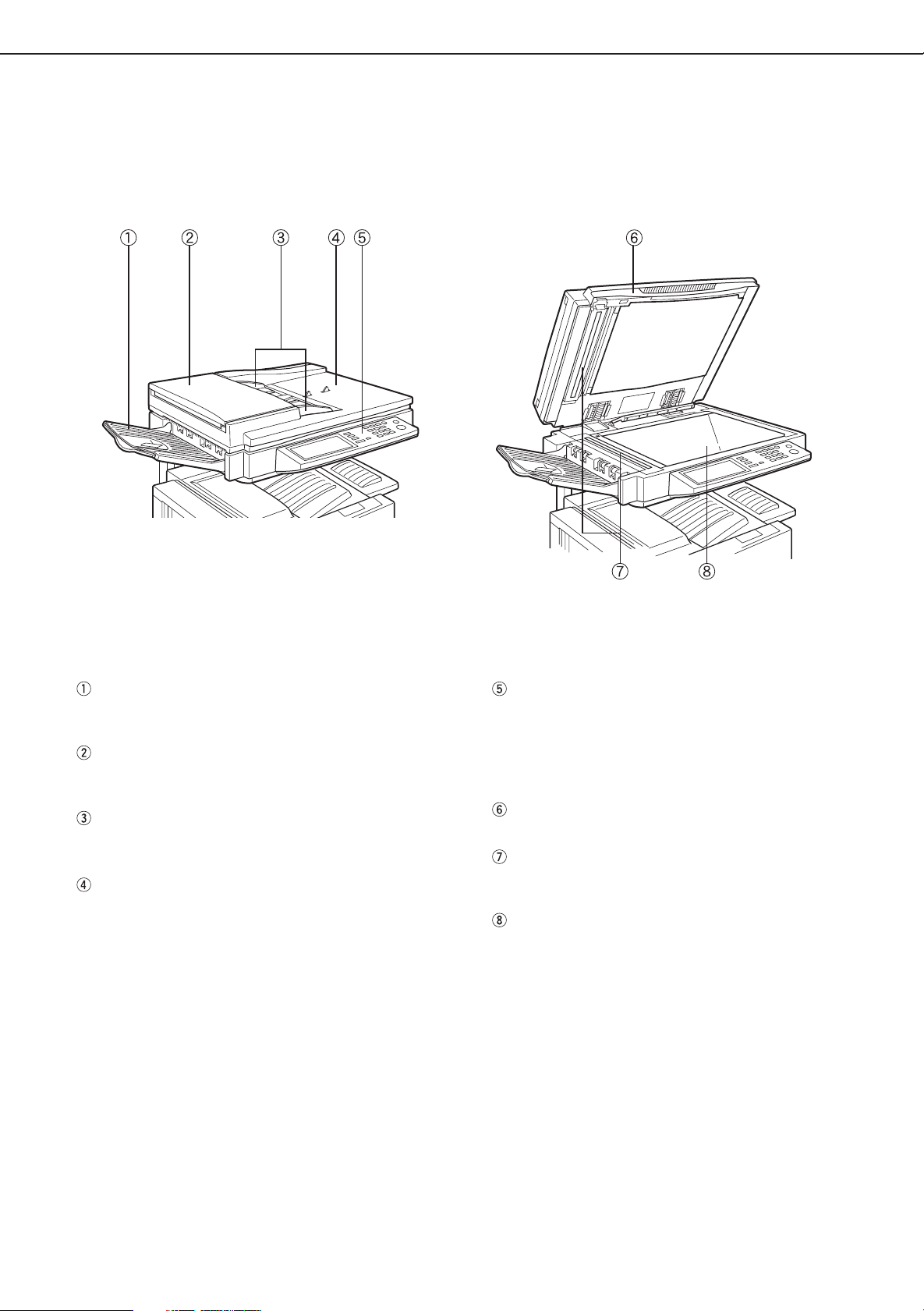
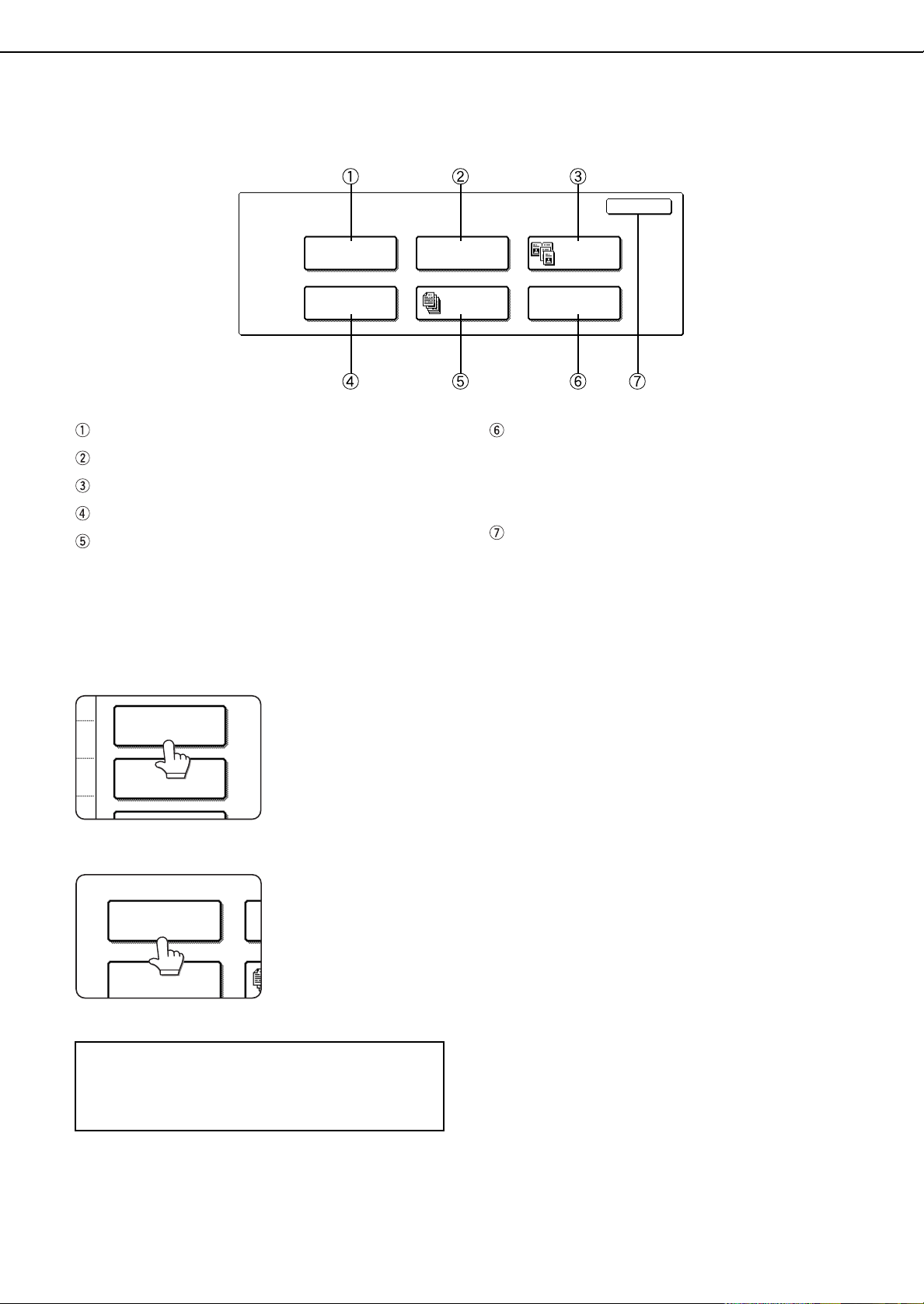
PART NAMES AND FUNCTIONS
(B/W scanner module/DSPF)
Exterior
DSPF exit area
Scanned originals are deposited here.
Document feeding area cover (page 29)
Open to remove misfed originals in this area.
Original guides (page 7)
Adjust to the size of the originals.
Document feeder tray (page 7)
Set the originals here for automatic feeding.
Operation panel (next page)
Use for operation of copier, network scanner, and
facsimile features and for printer configuration
operations.
Document cover
Document scanning windows
Sheet type originals are scanned here.
Document glass
All originals which cannot be copied from the
document feeder tray must be copied here.
3
Page 6
PART NAMES AND FUNCTIONS
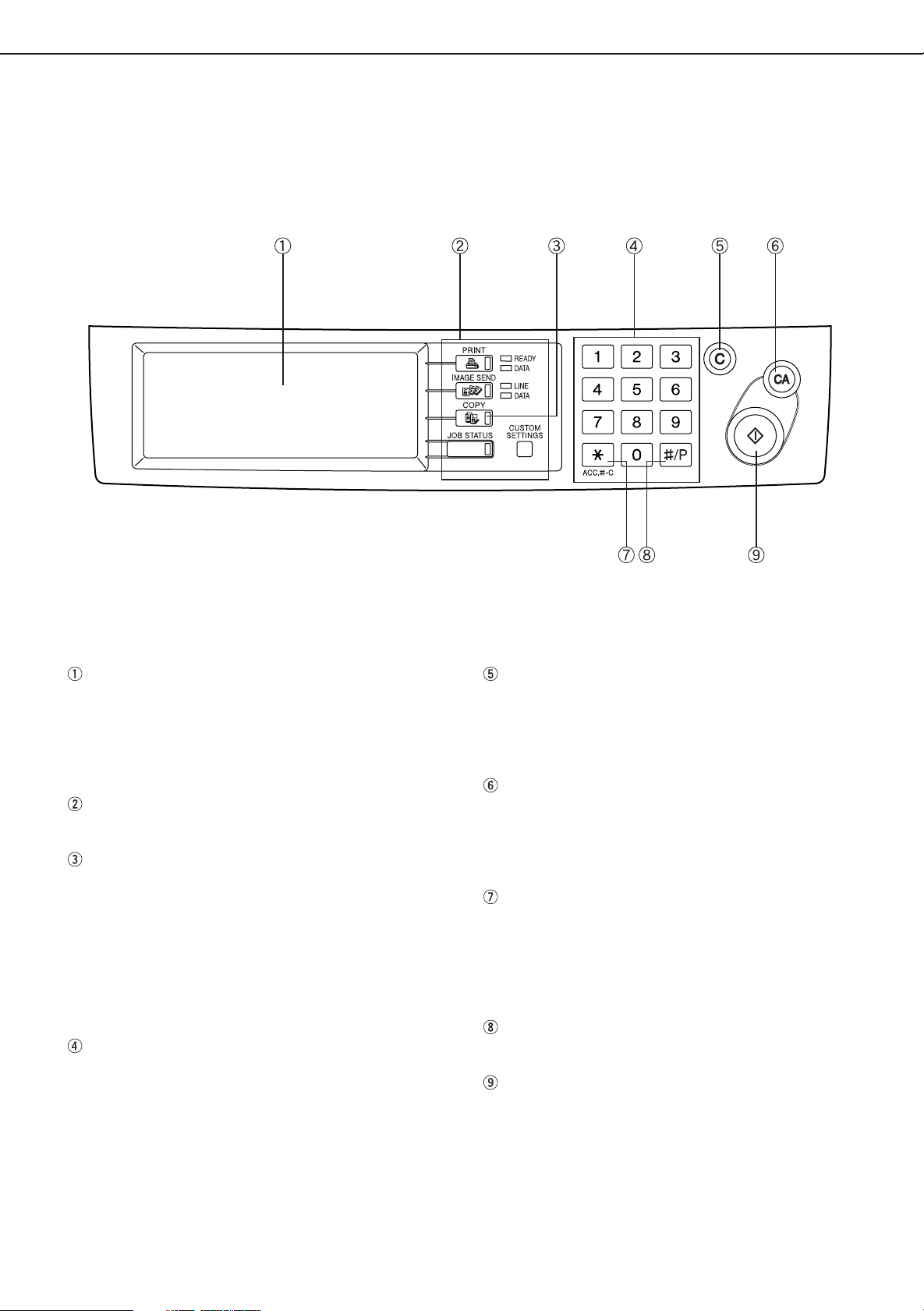
Operation Panel
Touch panel (next page)
The machine status, messages and touch keys are
displayed on the panel. When the machine is in the
standby state, the display will change if the [PRINT]
key, [IMAGE SEND] key or [COPY] key is pressed
to show the current status of these modes.
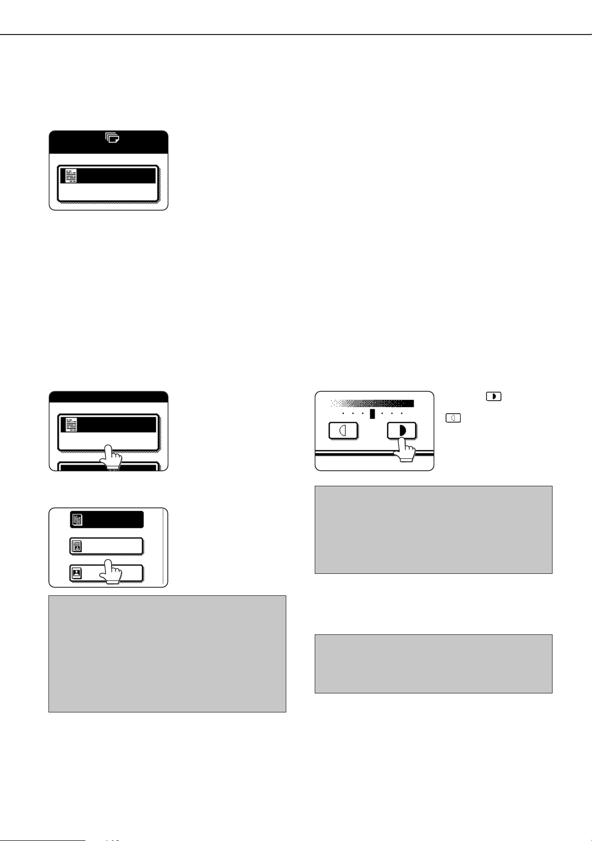
Mode select keys
Use to select the basic modes of the product.
[COPY] key
Press to select the copy mode and display the basic
screen of the copy mode. (next page)
Even when the machine is busy in another mode,
the basic copy mode screen will appear when the
[COPY] key is pressed. If this key is pressed and
held while the basic screen of the copy mode is
displayed, the total output count and the quantity of
toner remaining (percentage) will be displayed.
Numeric keys
Use to select the number of copies and to make
numerical entries for setting operations.
[C] key (clear key)
Press to clear a copy quantity entry. If this key is
pressed while the automatic document feeder is
being used, any originals in progress will be
automatically output.
[CA] key (clear all key)
Press to clear all selected settings and return the
machine to the initial settings for the currently
selected mode. Before starting a copy operation,
press the [CA] key first.
[ACC.#-C] key
If the auditing mode has been set, press this key to
close an open account after finishing a copy,
facsimile scanning or network scanning job. For
setting of the auditing mode, see page 7 of the Key
Operator’s Guide.
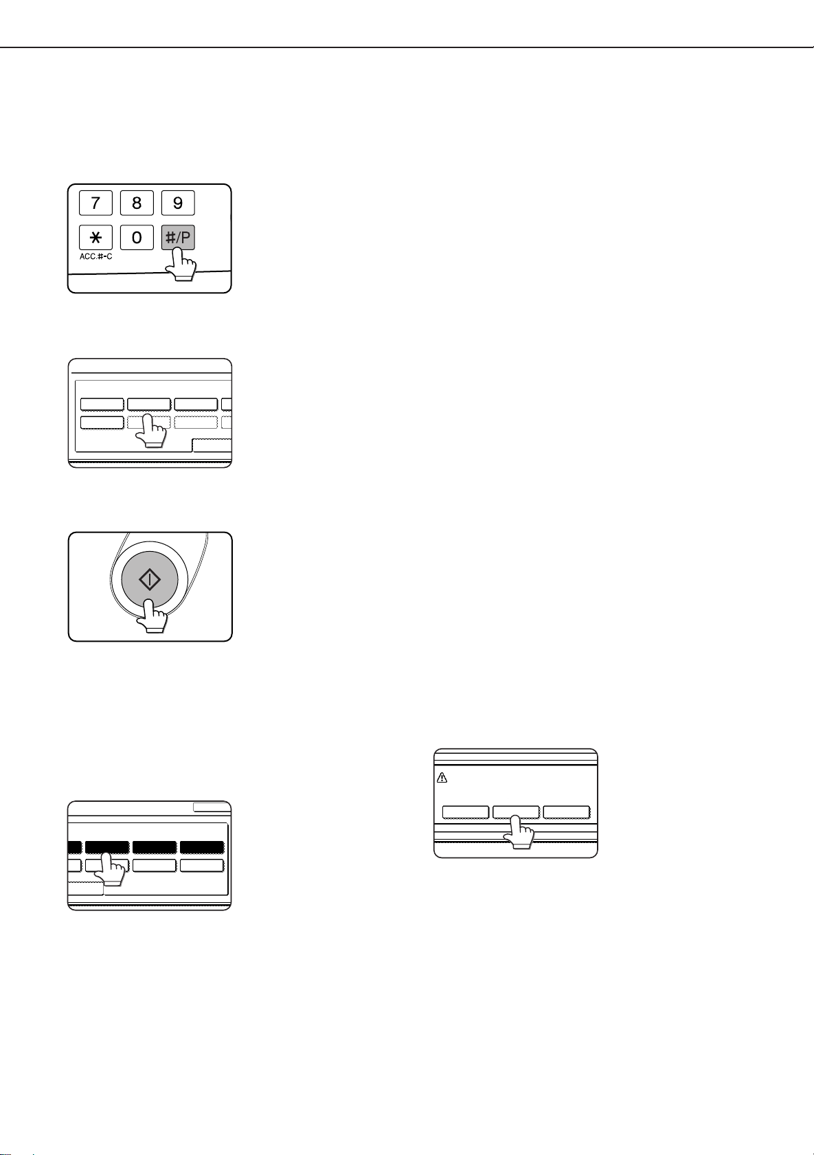
[#/P] key (page 26)
Press to select the job memory mode.
[START] key (page 10)
When the indicator is lit, copying, facsimile scanning
and network scanning jobs can be started. Press to
start copying.
4
Page 7
PART NAMES AND FUNCTIONS
SPECIAL MODES
ORIGINAL
EXPOSURE
AUTO
100%
AUTO
PAPER SELECT
COPY RATIO
READY TO SCAN FOR COPY.
2-SIDED COPY
OUTPUT
8
1
2
/
11
x
11 17
x
8
1
2
/
11
x
8
1
2
/
11
X
8
1
2
/
11
x
8
1
2
/
11
x
8
1
2
/
11
x
R
2.
1.
3.
4.
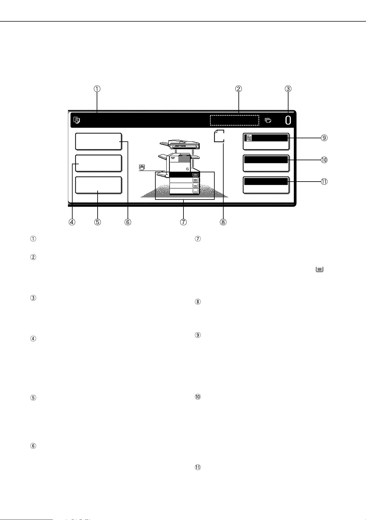
Touch Panel (basic screen of copy mode)
When the copy mode key is pressed, this display screen will appear showing the basic copy mode selections.
(For the display screens for other modes, see the respective operation manuals for those modes.)
Message display
Basic status messages are displayed here.
[INTERRUPT] key display area
When interrupt copy is available, the [INTERRUPT]
key will be displayed here. When an interrupt copy
job is being run, a [CANCEL] key will be displayed
here to be used for canceling the interrupt copy job.
Copy quantity display
Displays the selected number of copies before the
[START] key is pressed or the number of completed
copies after the [START] key is pressed. A single
copy can be made when “0” displayed.
[2-SIDED COPY] key (page 9)
Touch to display the duplex copy mode setting
screen. A highlighted selection on the screen will
indicate the currently selected mode. The setting
screen can be closed by touching the [OK] key on
the setting screen whether or not a selection change
was made.
[OUTPUT] key (page 10)
Touch to display the output mode setting screen. A
highlighted selection on the screen will indicate the
currently selected mode. The setting screen can be
closed by touching the [OK] key on the setting screen
whether or not a selection change was made.
[SPECIAL MODES] key
Touch to display the special modes selection screen.
The functions that can be selected by touching this
key are described on page 19.
Paper size display
The display shows the location of the paper trays,
the size of the paper in the trays and the approximate
amount of paper loaded in each tray. The approximate
amount of paper in a tray is indicated by .
For changing the paper size in a tray refer to page 116 of the “Operation manual (for printer operation
and general information)”.
Original size display
The original paper size will be displayed when originals
are placed on the document glass or in the document
feeder.
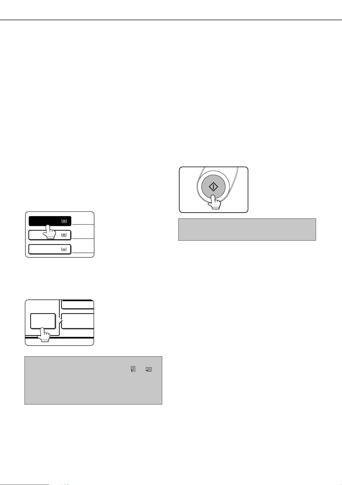
Exposure display and [EXPOSURE] key (page 15)
A touch of the [EXPOSURE] key will open the
exposure selection window. A highlighted key on the
exposure window indicates which exposure mode
(AUTO, TEXT, TEXT/PHOTO or PHOTO) is currently
selected. When an exposure mode other than AUTO
is selected, an exposure level scale will also appear
in the window.
Paper select display and [PAPER SELECT] key
(page 9)
Displays the selected paper size. When the auto
paper select mode has been selected, “AUTO” will
be displayed.
A touch of the [PAPER SELECT] key will open the
paper selection window. When a selection is made,
the selection window will close. To close the window
without making a selection touch the key again
Copy ratio display and [COPY RATIO] key
(page 17)
Displays the selected copy ratio.
Touch to display the reduction and enlargement copy
ratio selection screen.
5
Page 8
AUTOMATIC DOCUMENT FEEDER
Originals set in the automatic document feeder will be automatically fed and copied sequentially.
The automatic document feeder will simultaneously scan both sides of originals when two-sided to one-sided or two-
sided to two-sided copying is being done.
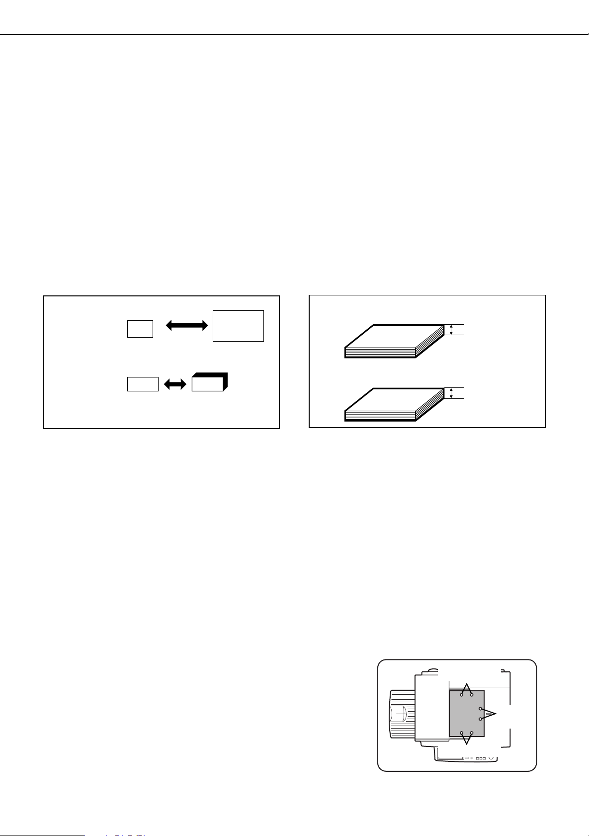
Acceptable originals
A stack of up to 50 original sheets (30 original sheets*1 for 8-1/2" x 14" (B4) or larger) of the same size paper can be
set in the document feeder tra y provided the stac k height is within the limit sho wn belo w.
A stack of up to 30 mixed size originals can be set if the width of the originals is the same and the stack height is within
the limit shown below . In this case , howe ve r, stapling and duple x will not function and some special functions ma y not
give the expected result.
*1 For paper heavier than 28 lbs. (105 g/m2), only a stack of up to 15 sheets can be set. Setting 16 or more sheets may
cause incorrect scanning of original and scanned image may become expanded compared with original itself.
■■
■ Size and weight of acceptable originals
■■
■■
■ Total amount of originals that can be
■■
set in the document feeder tray
5-1/2" x 8-1/2"
Original size:
Weight (thickness):
2
g/m
... Weight of a sheet of paper of 1 m
or A5
(148 x 210 mm)
14 lbs. or
50g/m
2
34 lbs. or
11" x 17"
or A3
(297 x 420 mm)
2
128g/m
2
Total aggregate thickness must not exceed 1/4" or
6.5 mm (for 14 to 21 lbs. or 50 to 80 g/m
Total aggregate thickness must not exceed 3/16" or
5.0 mm (for 21 to 34 lbs. or 80 to 128 g/m
2
paper).
1/4" or 6.5 mm
or less
2
3/16" or 5.0 mm
or less
Notes on use of the automatic document feeder
●
Use originals within the specified size and weight ranges. Use of originals out of the specified range may cause
an original misfeed.
●
Before loading originals into the document feeder tr a y, be sure to remove an y staples or paper clips.
●
If originals have damp spots from correction fluid, ink or glue from pasteups, be sure they are dried before they
are fed. If not, the interior of the document feeder or the document glass may be soiled.
●
To prevent incorrect original size detection, original misf eeds or smudges on copies, use the f ollowing as a guide
for feeding originals.
Transparency film, tracing paper , carbon paper , thermal paper or originals printed with thermal transfer ink
ribbon should not be fed through the document f eeder . Originals to be fed through the feeder should not be
damaged, crumpled or folded or have loosely pasted paper on them or cutouts in them. Originals with multiple
punched holes other than two-hole or three-hole punched paper may not f eed correctly .
●
When using originals with two or three holes, place them so that the punched edge is at a position other than the
feed slot.
paper).
6
Hole positions
Hole
positions
Hole positions
Page 9
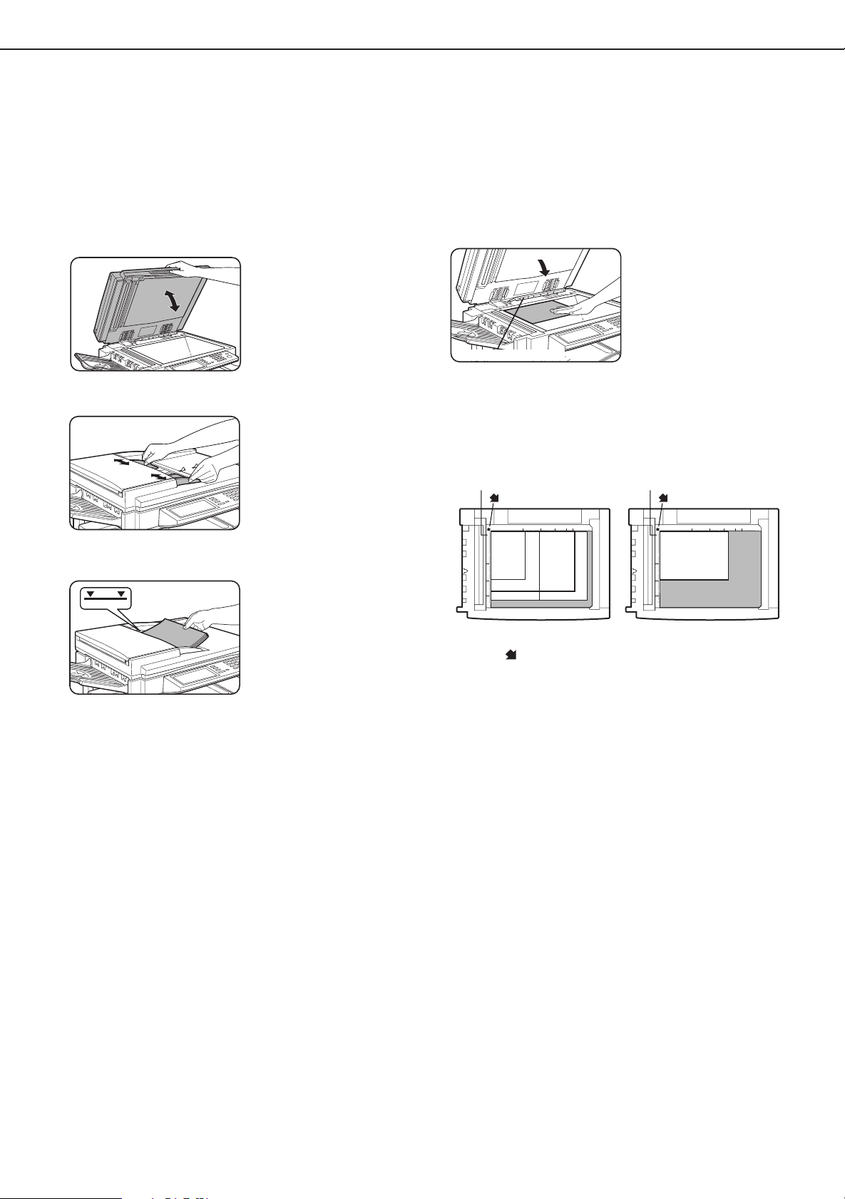
SETTING ORIGINALS
Original size detector
or B4
Original scale
mark
Original scale
mark
8
1
2
/
x
11 or A4
8
1
2
/
x
11R or A4R
8
1
2
/
x
14
11x17 or A3
or B4
5
1
2
/
8
1
2
/
x
or A5
■■
■ When using the automatic document
■■
feeder
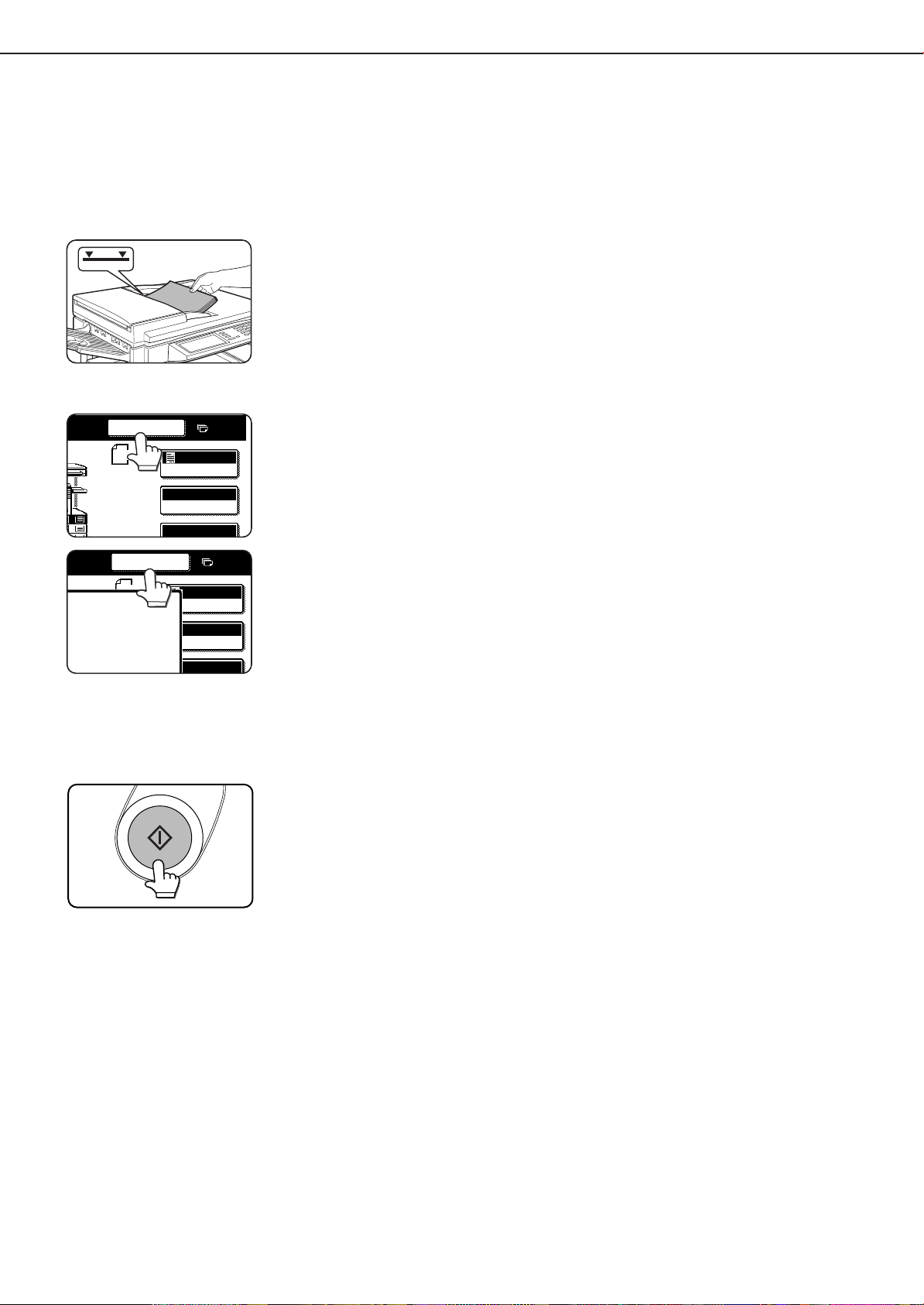
Ensure that there is no original on the document
1
glass.
Adjust the original guides to the size of the
2
originals.
Place the originals face down in the document
3
feeder tray.
Set the originals all the way
into the feed slot. Do not
exceed the maximum
height line marked on the
original guide.
■■
■ When using the document glass
■■
Open the document cover, place an original face
down on the document glass, and then gently
close the document cover.
NOTE
Do not place any objects under the original size
detector, because they may damage it or the original
size may not be detected properly.
●
Set an original by aligning its corner with the tip of the
scale ( ) mark at the left rear corner of the glass as
shown in the illustrations.
7
Page 10
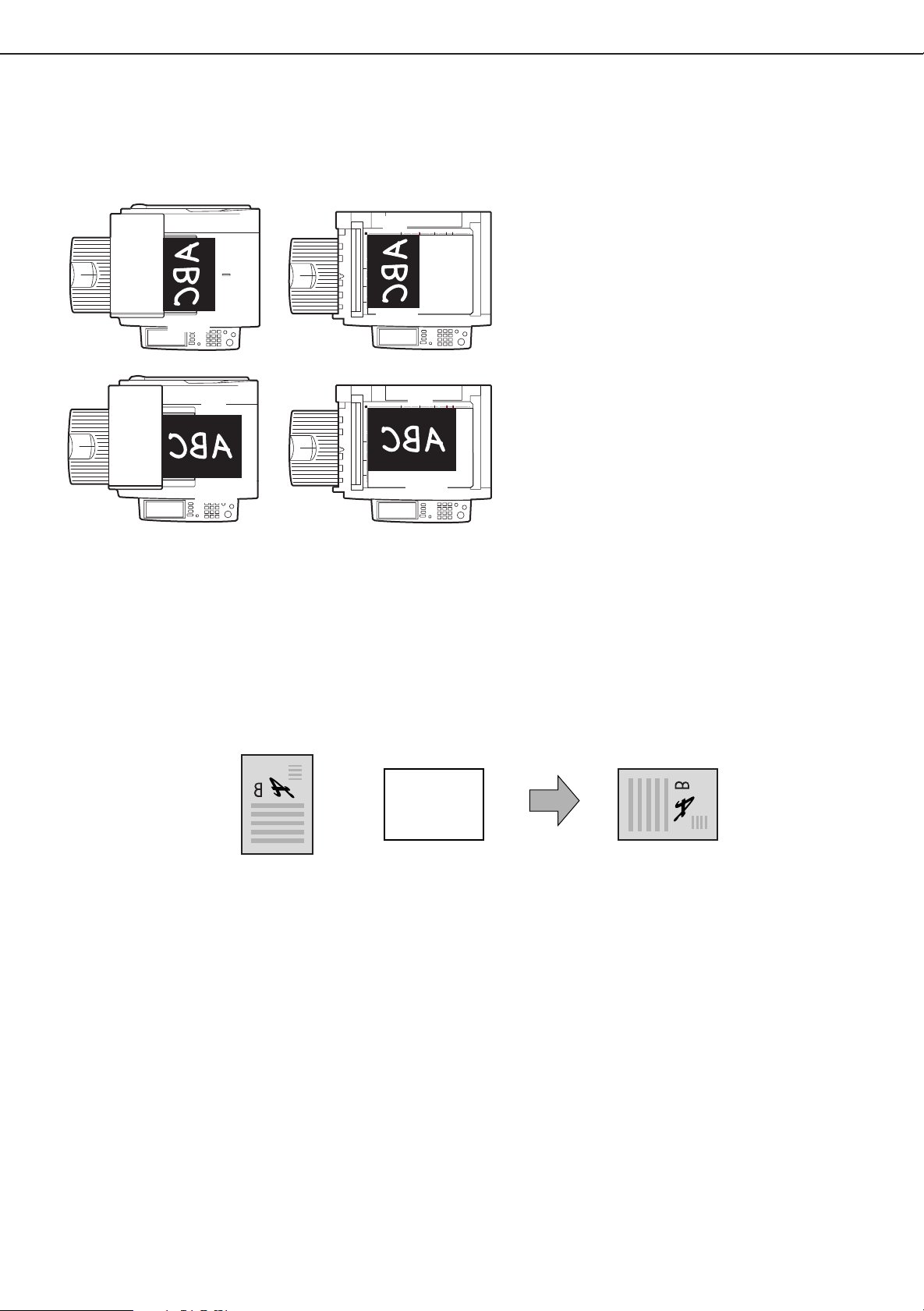
Orientation of original Orientation of paper Copy after rotation
Face down Face down
SETTING ORIGINALS
To p
To p
To p
Bottom
Bottom
Bottom
To p
Bottom
■■
■ Standard original setting orientation
■■
Descriptions of functions that follow in this manual assume that originals are oriented as shown.
Document feeder tray Document glass
Place originals in the document feeder tray or on
the document glass so that the top of the original
is positioned to the rear side of the machine. If
not, staples will be incorrectly positioned and
some special features may not give the expected
result.
■■
■ Automatic copy image rotation - rotation copying
■■
If the orientation of the originals and copy paper are different, the original image will be automatically rotated 90°
and copied. (When an image is rotated, a message will be displayed.) When enlargement of originals larger than 81/2" x 11" or A4 is selected, rotation cannot be done.
[Example]
●
This function operates in the auto paper select or auto image mode. (Rotation copying can be disabled
with a key operator program. See page 33.)
8
Page 11
NORMAL COPYING
OK
0
AUTO
PAPER SELECT
100%
8
1
2
/
11
X
TRANSPA
8
1
2
/
11
X
8
1
2
/
11
X
11 17
x
1.
2.
3.
PLAIN
PLAIN
This section describes the normal copying procedure.
Copying from the automatic document feeder
■■
■ 1-sided copies of 1-sided originals
■■
Original Copy
Place the originals in the document feeder tray .
1
(page 7)
Ensure that the 1-sided to 1-sided copy mode is
2
selected.
1
/
2
8
ORIGINAL
1
/
x
2
8
11
1
/
x
1.
2
8
11
1
/
x
2.
2
8
11
x
3.
11 17
1
/
x
4.
2
8
R
11
T ouch the [2-SIDED COPY] key.
3
The one-sided to one-
x
11
sided mode is selected
when no icon for a twosided mode appears in the
dashed area on the display.
If the 1-sided to 1-sided
copy mode is already
selected, steps 3 to 5 are
not needed.
2-SIDED COPY
OUTPUT
T ouch the [1-sided to 1-sided copy] ke y .
4
The [1-sided to 1-sided] key
will be highlighted.
T ouch the [OK] key.
5
Ensure that paper of the same size as the
6
originals is automatically selected. (✼Note)
The selected tray will be
highlighted or the message
“LOAD xxxxxx PAPER.” will
appear. If the message appears, load paper in a paper tray or the bypass tray
with paper of the required
size. Even if the message
above is displayed, copying can be performed onto
the currently selected paper.
(✼Note) The following requirements must be satisfied.
●
Originals of a standard size (11" x 17", 8-1/2" x 14", 8-1/2"
x 11", 8-1/2" x 11"R, 5-1/2" x 8-1/2", A3, B4, A4, A4R or A5)
are set and the auto paper select function is enabled.
If originals of a size other
than the sizes above are to
be copied, manually select
the desired paper size.
9
Page 12
2-SIDED COPY
OUTPUT
NORMAL COPYING
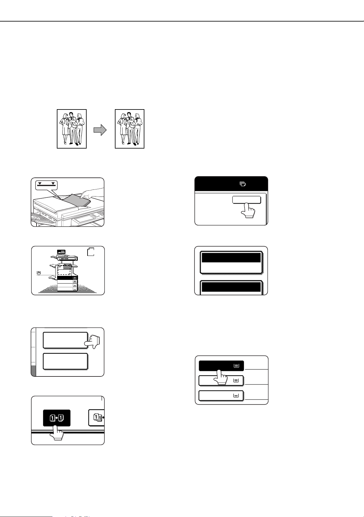
Five sets of copiesOriginals
Five copies of each original
Originals
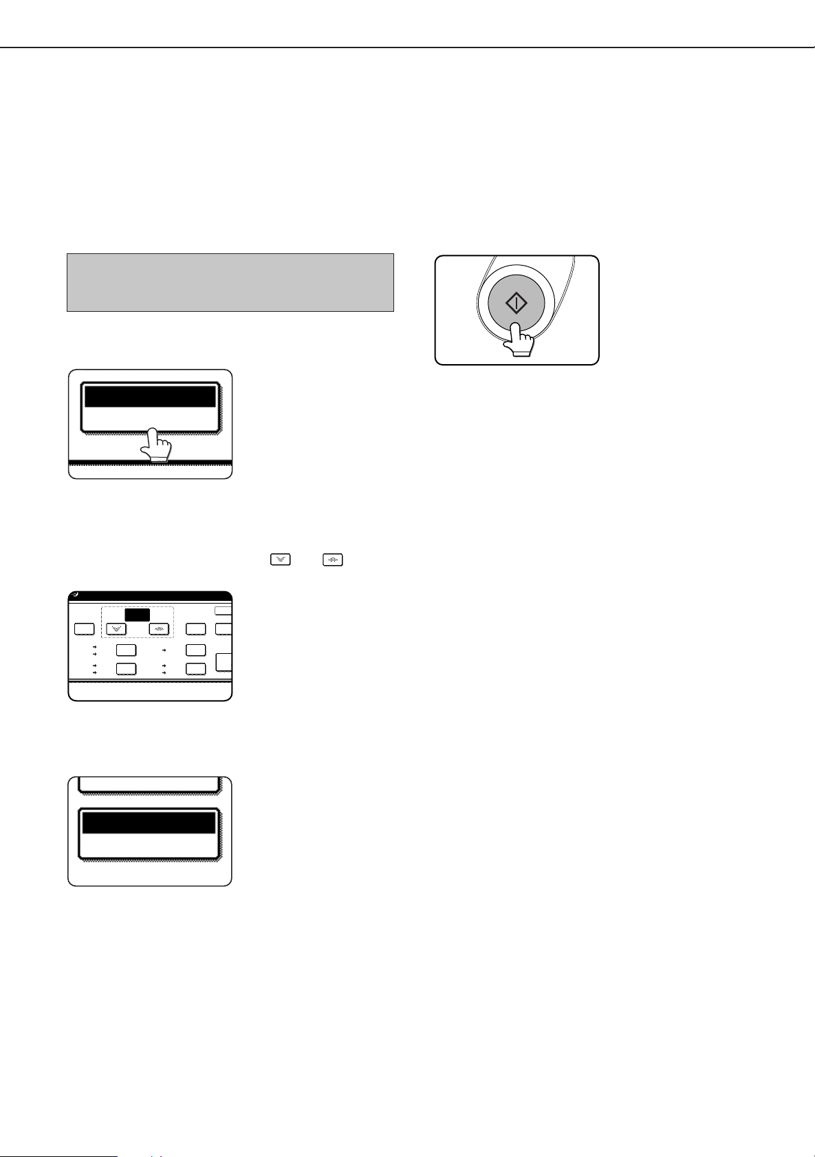
Select the desired output mode (see below).
7
The sort mode is the default
mode. To select the group
mode, touch the [OUTPUT]
key, then touch the
[GROUP] key on the output
setting screen, and then
touch the [OK] key on the
setting screen.
Use the numeric keys to set the desired number
8
of copies.
Up to 999 can be set.
Use the [C] (clear) key to
cancel an entry if a mistake
has been made.
Press the [START] key.
9
If the [C] key is pressed
while originals are being
scanned, scanning will
stop. If copying had already
started, copying and
scanning will stop after the
original in progress is
output to the original exit
area. In these cases the
copy quantity will be reset
to “0”. If scanning has been
completed but copying is
still in progress, copying will
continue.
NOTE
The 1-sided to 1-sided copying mode is set as the default
in the initial settings. This setting can be changed by a key
operator program (initial status setting ).
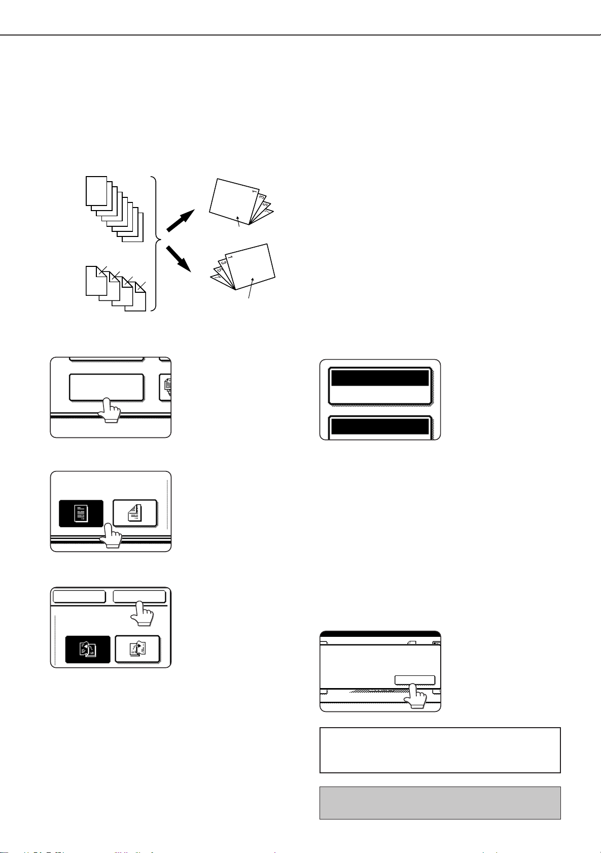
Output modes (sort mode and group mode)
[Example] Five sets of copies from three originals
● Sort copy
● Group copy
10
When originals are placed in the document feeder tray, a
sort icon will appear on the touch panel and the sort
copy mode will be automatically selected. In this case,
copies will be delivered as shown in the upper illustration
to the left. For output in the group mode as shown in the
lower left illustration, the group mode must be selected
on the output setting screen.
Page 13
BIN
CH
NORMAL COPYING
BINDING
CHANGE
OK
A utomatic two-sided copying from the automatic document
feeder
A duplex module must be installed for automatic 1-sided to 2-sided or 2-sided to 2-sided copying. A duplex module is
not needed for 2-sided to 1-sided copying.
Original
Copy
1. Automatic two-sided copying from one-sided
originals
2. Automatic two-sided copying from two-sided
originals
Place the originals in the document feeder tray .
1
(page 7)
T ouch the [2-SIDED COPY] key.
2
2-SIDED COPY
OUTPUT
Select the desired duplex copy mode.
3
The illustration to the left
shows the screen
displayed when a duplex
module is installed.
3. Automatic one-sided copying from two-sided
originals
T ouch the [OK] key.
4
Follow step 6 on page 9 to step 9 on page 10.
The image to be copied onto the second side of 2-sided
copies can be inverted so that the resultant 2-sided copies
are in the correct orientation for binding at the top. For top
binding, touch the [BINDING CHANGE] key on the 2-sided
copy selection screen.
11
Page 14
AUTO
PAPER SELECT
100%
8
1
2
/
11
X
TRANSPA
8
1
2
/
11
X
8
1
2
/
11
X
11 17
x
1.
2.
3.
PLAIN
PLAIN
NORMAL COPYING
Copying from the document glass
When copying originals which cannot be fed from the automatic document feeder such as thick originals, open the
document cover and copy the originals from the document glass
■■
■ 1-sided copies of 1-sided originals
■■
Original Copy
Set an original on the document glass. (page 7)
1
Original size detector
Original scale
mark
1
1
x
/
/
5
8
2
2
or A5
1
x
/
8
11 or A4
2
●
Set an original by aligning its corner with the tip of the
scale (
1
x
/
8
2
14
or B4
or B4
11x17 or A3
) mark at the left rear corner of the glass as shown
Original scale
mark
1
x
/
8
11R or A4R
2
in the illustrations.
Ensure that paper of the same size as the original
3
is automatically selected. (✼Note)
The selected tray will be
highlighted or the message
“LOAD xxxxxx PAPER.” will
appear. If the message
appears, load paper in a
paper tray or the bypass tray
with paper of the required
size. Even if the message
above is displayed,
copying can be performed
onto the currently selected
paper.
(✼Note) The following conditions must be satisfied.
●
Originals of a standard size (11" x 17", 8-1/2" x 14", 8-1/2"
x 11", 8-1/2" x 11"R, 5-1/2" x 8-1/2", A3, B4, A4, A4R or A5)
are set and the auto paper select function is enabled.
If originals of a size other
than the sizes above are to
be copied, manually select
the desired paper size.
Ensure that the 1-sided to 1-sided copy mode is
2
selected.
ORIGINAL
1
/
x
2
8
11
1
/
x
1.
2
8
11
1
/
x
2.
2
8
11
x
3.
11 17
1
/
x
4.
2
8
R
11
12
1
/
2
8
The one-sided to one-
x
11
sided mode is selected
when no icon for a twosided mode appears in the
dashed area on the display.
If the 1-sided to 1-sided
copy mode is already
selected, steps 3 to 5 are
not needed.
Page 15
2-SIDED COPY
OUTPUT
NORMAL COPYING
Five sets of copiesOriginals
PLACE NEXT ORIGINAL. PRESS [START].
WHEN FINISHED, PRESS [READ-END].
READ-END
Five copies of each original
Originals
Select the desired output mode (see below).
4
When a document is
detected on the document
glass, the group mode will
be automatically selected.
To select sort copy, touch
the [OUTPUT] key, then
touch the [SORT] key on the
displayed screen, and then
touch the [OK] key.
NOTE
If you touch the [SORT] or [GROUP] key, its corresponding
icon will appear on the touch panel. To change the
selection, touch the icon to return the display to the output
setting screen.
Use the numeric keys to set the desired number
5
of copies.
Up to 999 can be set.
Use the [C] (clear) key to
cancel an entry if a mistake
has been made.
Press the [START] key.
6
Touch the [READ-END] key.
7
Replace the original with
the next original and press
the [START] key. Repeat
this operation until all
originals have been
scanned.
If sort was selected in step
4, go to the next step.
Output mode (sort copy and group copy)
[Example] Five sets of copies from three originals
●●
●
●●
Sort copy
●●
●
●●
Group copy
When originals are placed in the document feeder tray, a
sort icon will appear on the touch panel and the sort
copy mode will be automatically selected. In this case,
copies will be delivered as shown in the upper illustration
to the left. For output in the group mode as shown in the
lower left illustration, the group mode must be selected
on the output setting screen.
13
Page 16
2-SIDED COPY
OUTPUT
Original Copy
NORMAL COPYING
BINDING
CHANGE
OK
Automatic two-sided copying from the document glass
A duplex module must be installed for automatic 1-sided to 2-sided or 2-sided to 2-sided copying. A duplex module is
not needed for 2-sided to 1-sided copying.
Place an original on the document glass.
1
(page 7)
Touch the [2-SIDED COPY] key.
2
Touch the [1-sided to 2-sided copy] key.
3
The image to be copied onto the second side of 2-sided
copies can be inverted so that the resultant 2-sided copies
are in the correct orientation for binding at the top. For top
binding, touch the [BINDING CHANGE] key on the 2-sided
copy selection screen.
Touch the [OK] key.
4
Follow step 3 on page 12 to step 7 on page 13.
14
Page 17
EXPOSURE ADJUSTMENTS
0
AUTO
EXPOSURE
0
AUTO
EXPOSURE
PHOTO
TEXT
TEXT
/
PHOTO
1
3
5
Select the exposure mode to be consistent with the type of originals to be copied. The selections are AUTO, TEXT,
TEXT/PHOTO and PHOTO.
■■
■ Automatic exposure adjustment
■■
The automatic exposure
mode is the default initial
setting for this machine. In
this mode, the
characteristics of an
original being copied are
“read” by the exposure
system, and exposure
adjustments are made
automatically. To select an
exposure mode more
suitable for originals to be
copied or to adjust the
exposure manually, follow
the procedure below.
■■
■ Exposure mode selection and manual
■■
exposure adjustment
Touch the [EXPOSURE] key.
1
Select [TEXT], [TEXT/PHOTO] or [PHOTO] based
2
on the original to be copied.
NOTE
Exposure mode selection
TEXT: This mode is useful for producing dark
text copies with minimum background.
TEXT/PHOTO: This provides the best balance for copying
an original which contains both text and
photos. This mode is also useful for
copying printed photographs.
PHOTO: This mode provides the best copies of
photographs with fine details.
Adjust the exposure level.
3
Touch the key to make
darker copies. Touch the
key to make lighter
copies.
NOTE
Exposure levels in the text mode
1 to 2: Dark originals such as newspaper
3: Normal density originals
4 to 5: Originals written with pencils or light color
characters
After adjusting the exposure, follow any of the copying
procedures.
To return to the automatic exposure mode, touch the
[EXPOSURE] key and select [AUTO]. The automatic
exposure level can be adjusted using a key operator
program. (page 33)
15
Page 18
REDUCTION/ENLARGEMENT/ZOOM
TRANSPA
8
1
2
/
11
X
8
1
2
/
11
X
11 17
x
1.
2.
3.
PLAIN
PLAIN
8
2
1
AUTO
COPY RATIO
PAPER SELEC
AUTO
IMAGE
Reduction and enlargement ratios can be selected either automatically or manually as described in this section.
●
Automatic selection will enlarge or reduce images based upon the original size and copy paper size to give the best
possible fit of the image to the copy paper.
●
Manual selections can be made in the range of 25% to 400%. There are three preset reduction ratios (25%, 64% and
77%) and three preset enlargement ratios (121%, 129% and 400%) available for the inch system. There are four
preset reduction ratios (25%, 70%, 81%, 86%) and four preset enlargement ratios (115%, 122%, 141%, 400%)
available for the AB system.
Automatic selection (auto image)
The reduction or enlargement ratio will be selected automatically based on the original size and the selected pape
size
Place the original in the document feeder tray
1
or on the document glass. (page 7)
The detected original size will be displayed.
Automatic selection can be used only for 11" x 17", 81/2" x 14", 8-1/2" x 11", 8-1/2" x 11"R, 5-1/2" x 8-1/2"
size originals and copy paper in the inch system and
A3, B4, A4, A4R or A5 in the AB system.
Touch the [PAPER SELECT] key and then select
2
the desired paper size.
When the desired paper
size key is touched, the
paper size will be
highlighted and the paper
size setting window will be
closed.
If paper of the desired size
is not loaded in any tray,
load paper of the required
size in a paper tray and
enter the paper size.
Touch the [AUTO IMAGE] key.
3
The [AUTO IMAGE] key will
be highlighted and the best
reduction or enlargement
ratio for the original size
and the selected paper
size will be selected and
displayed in the copy ratio
display.
Make all other desired settings such as exposure
4
or the number of copies, and press the [START]
key.
When copying from the
document glass in the sort
mode, touch the [READEND] key after all originals
have been scanned. (step
7 on page 13)
To cancel the auto image mode, touch the [AUTO IMAGE]
key again to clear the highlighted display.
NOTE
If the message “ROTATE ORIGINAL FROM
displayed, change the orientation of the original as
indicated in the message. When the message above is
displayed, copying can be done without changing the
orientation, but the image will not fit the paper correctly.
16
TO ” is
Page 19
Manual selection
100
%
COPY RATIO
OK
AUT
IMAG
10400
%
25
%
121
%
129
%
64
%
77
%
100
ZOOM
%
11 17
x
11 17
x
8
1
2
/
11
x
8
1
2
/
11
x
8
1
2
/
14
x
11 17
x
8
1
2
/
11
x
11 17
x
8
1
2
/
14
x
8
1
2
/
11
x
8
1
2
/
14
x
8
1
2
/
11
x
5
1
2
/
8
1
2
/
x
5
1
2
/
8
1
2
/
x
P PER SELECT
COPY RATIO
77
%
REDUCTION/ENLARGEMENT/ZOOM
Place the original in the document feeder tray
1
or on the document glass. (page 7)
NOTE
When the document feeder is being used, the available
copy ratio range is 25% to 200%.
Touch the [COPY RATIO] key.
2
The preset copy ratio keys
for reduction and
enlargement, the keys for
[ZOOM] and the [100%] key
will be displayed.
Select the desired copy ratio by touching a fixed
3
copy ratio key for reduction or enlargement and
touch the [OK] key. Use the and keys to
make fine adjustments as needed.
If the message “IMAGE IS
LARGER THAN THE COPY
PAPER.” appears, image
loss will occur. In this case
either continue with image
loss or change the copy
paper size or copy ratio.
Make all other desired settings such as exposure
5
or the number of copies and press the [START]
key.
When copying from the
document glass in the sort
mode, touch the [READEND] key after all originals
have been scanned. (step
7 on page 13)
Ensure that the desired paper size has been
4
automatically selected based on the selected
copy ratio or select another size as needed.
If another size paper is
selected, the auto paper
select display will be
cleared.
17
Page 20
SPECIAL PAPERS
1.
2.
3.
COLOR
BYPASS
If a bypass tray and a duplex module, a duplex module/bypass tray or a multi purpose drawer*1 is installed, special
papers can be fed. These include transparency film, postcards, labels, envelopes*2, and plain paper.
*1 The upper tray of a stand/3 x 500 sheet paper drawer or a stand/MPD & 2000 sheet paper drawer is equivalent to
the multi purpose drawer.
*2 Envelopes can be set in the multi purpose drawer and in the upper tray of a stand/paper drawer.
Place the original in the document feeder tray
1
or on the document glass. (page 7)
Load the special paper in the bypass tray or in
2
the multi purpose drawer.
For the paper loading instructions see “Loading paper
in the bypass tray” (page 5-3) of the “Operation manual
(for printer operation and general information)” or
“Loading paper in the multi purpose drawer” (page
1-21) of the “Operation manual (for printer operation
and general information)”.
Touch the [PAPER SELECT] key and then select
3
the bypass tray or the multi purpose drawer.
Make all other desired settings such as exposure
4
or the number of copies, and press the [START]
key.
When copying from the
document glass in the sort
mode, touch the [READEND] key after all originals
have been scanned. (step
7 on page 13)
18
Page 21
SPECIAL MODE
When the [SPECIAL MODES] key on the basic screen of the copy mode is touched, the special modes screen
containing six special function touch keys will appear. These functions are sho wn below.
SPECIAL MODES
Margin shift: page 20
Erase: page 21
Dual page copy: page 22
Pamphlet copy: page 23
Job build: page 24
MARGIN SHIFT
PAMPHLET COPY
ERASE
JOB BUILD
Multi shot: page 25
When using the multi shot function, set the original,
select the desired paper, and select one-sided or
two-sided copying before selecting the multi shot
function on the special modes screen.
[OK] key on the special modes screen
Touch the [OK] key, to return to the basic screen of
the copy mode.
DUAL PAGE
COPY
MULTI SHOT
OK
Common operation procedure for using the special functions
T ouch the [SPECIAL MODES] key.
1
SPECIAL MODES
2-SIDED COPY
T ouch the key f or the desired special mode.
2
Example:
To set the margin shift
MARGIN SHIFT
function:
PAMPHLET COPY
Setting procedures for modes requiring setting
screens start on the next page. The dual page
copy and job build functions do not require setting
screens.
19
Page 22
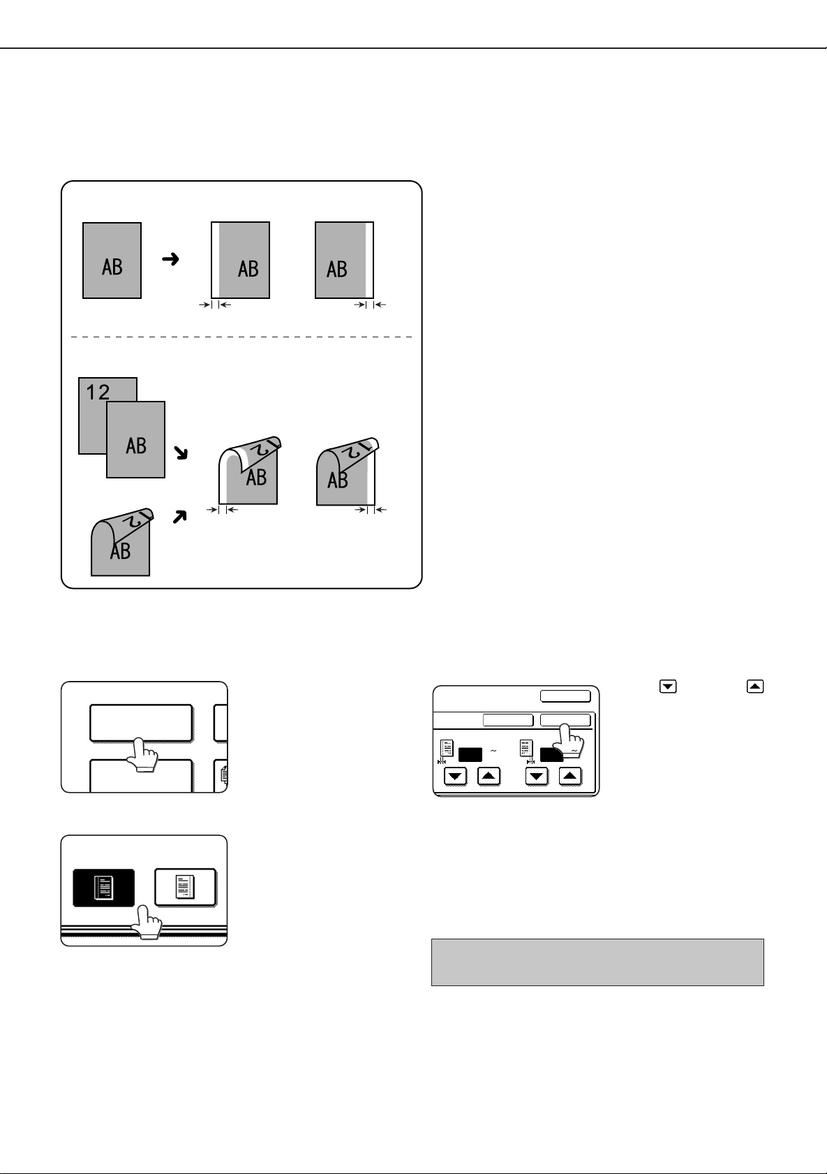
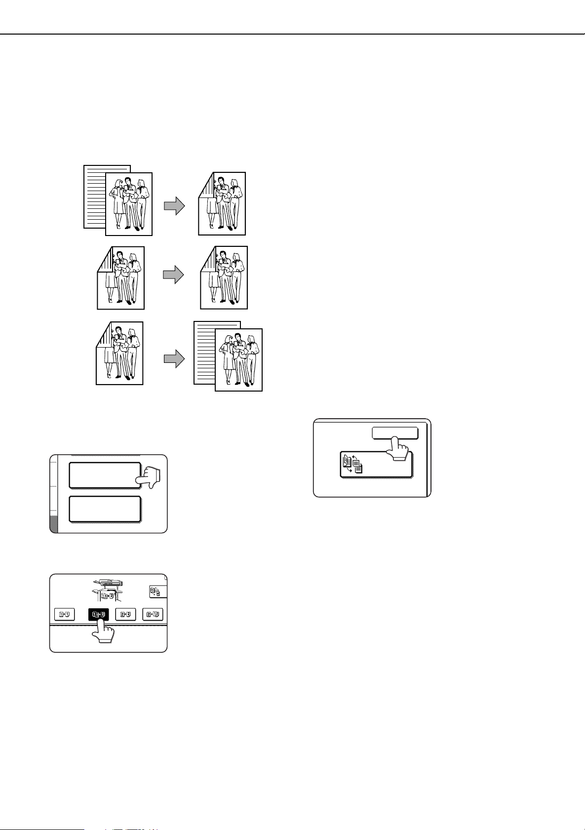
MARGIN SHIFT
PAMPHLET COPY
RIGHT LEFT
Two-sided copying
Original
One-sided copying
Image shifted
to the right
Image shifted
to the left
Original
Image shifted
to the right
Image shifted
to the left
Margin
Margin
or
Margin
Margin
inch
1/2
(0 1)
SIDE 2
OK
OK
CANCEL
SIDE 1
inch
3/8
(0 1)
SPECIAL FUNCTIONS
Margin shift
The margin shift function will automatically shift the text or image on the copy paper approximately 1/2" (10 mm) in its
initial setting.
●
The shift direction can be selected from right or left
shift as shown in the illustration.
Touch the [MARGIN SHIFT] key on the SPECIAL
1
MODES screen.
Select the shift direction.
2
The margin shift setting
screen will appear.
Touch a shift direction key
to select right or left. The
selected key will be
highlighted.
Set the shift amount as needed and touch the
3
[OK] key.
Use the key and the
keys to set the shift amount.
The shift amount can be
set from 0" to 1" in 1/8"
increments ( 0 mm to 20 mm
in 1 mm increments for the
AB system). If a duplex
module is not installed, the
shift amount setting for the
reverse side is not
displayed.
Touch the [OK] key on the special modes screen.
4
After adjusting the exposure, follow any of the
copying procedures.
To cancel the margin shift function, touch the [CANCEL]
key on the margin shift setting screen.
20
Page 23
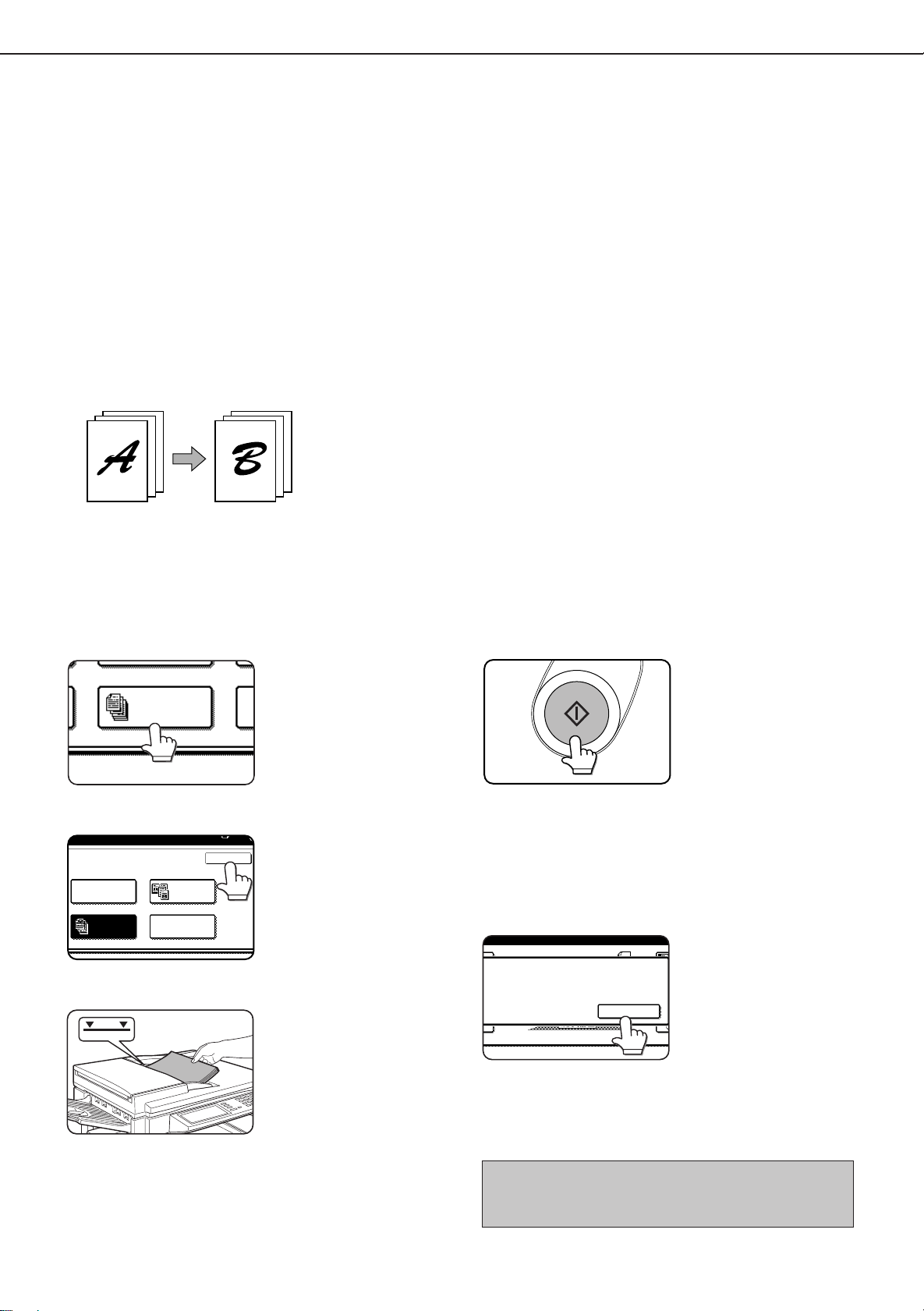
JOB BUILD
ERASE
ERASE
EDGE
ERASE
CENTER
ERASE
EDGE+CENTER
ERASE
inch
1/2
(0 1)
EDGE
CANCEL OK
Original
Copy
SPECIAL FUNCTIONS
Erase
The erase function is used to erase the shadow lines on copies produced when copying thick originals or books. The
erase modes that can be selected are shown below. The erase width is approximately 1/2" (10 mm) in it’s initial setting.
Edge erase
Eliminates shadow lines around the edges of copies
caused when thick paper or a book is used as an original.
Center erase
Eliminates shadow lines produced by the bindings of
bound documents.
Edge + center erase
Eliminates shadow lines around the edges of copies and
eliminates the shadow at the center of copies.
Touch the [ERASE] key on the SPECIAL MODES
1
screen.
The erase setting screen
will appear.
Select the desired erase mode.
2
Select one of the three
erase modes. The selected
key will be highlighted.
Adjust the amount of erase and touch the [OK]
3
key.
Use the and keys to
adjust the erase width and
then touch the [OK] key.
Touch the [OK] key on the special modes screen.
4
After adjusting the exposure, follow any of the
copying procedures.
To cancel the erase function, touch the [CANCEL] key on
the erase setting screen.
21
Page 24
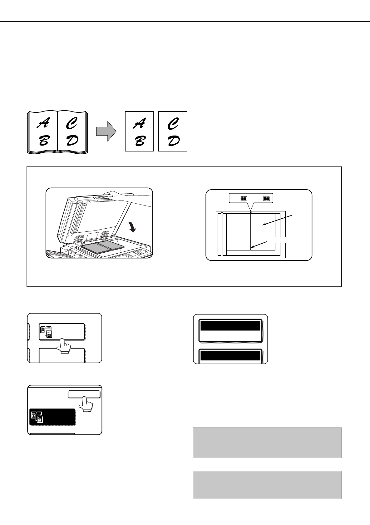
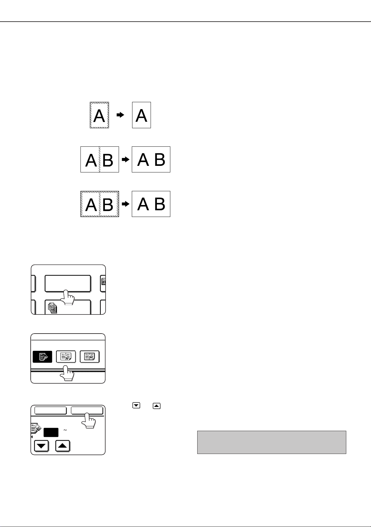
MULTI SHOT
DUAL PAGE
COPY
OK
DUAL PAGE
COPY
Center line of
original
Index
This page
is copied
first.
8
1
2
/
x
11 or A4
Dual page copy
Book original
PAPER SELECT
AUTO
100%
8
1
2
/
11
x
SPECIAL FUNCTIONS
Dual page copy
The dual page copy function produces separate copies of two documents placed side by side on the document glass.
It is especially useful when copying books and other bound documents.
[Example] Copying right and left pages of a book
●
The dual page copy function can be used with reduction
copying but cannot be used with enlargement copying.
●
The dual page copy function can be done only from
the document glass. The automatic document feeder
cannot be used with this function.
●
Only 8-1/2" x 11" or A4 paper can be used.
When copying book originals:
When copying a thick book, press down lightly on
the document cover.
Touch the [DUAL PAGE COPY] key on the
1
SPECIAL MODES screen.
Touch the [OK] key on the special modes screen.
2
Place the originals on the document glass.
3
22
The [DUAL PAGE COPY]
key will be highlighted.
Ensure that 8-1/2" x 11" or A4 size paper is
4
selected.
If 8-1/2" x 11" or A4 size
paper is not selected, touch
the [PAPER SELECT] key
to select 8-1/2" x 11" or A4
size paper.
After adjusting the exposure, follow any of the
copying procedures. When copying onto two sides
of paper, follow steps 2 to 4 on page 14 and then
follow steps 4 to 7 on page 13.
When copying onto one side of paper, follow steps 4
to 7 on page 13.
To cancel the dual page copy function, touch the [DUAL
PAGE COPY] key on the special modes screen (step 1).
(The highlighted display will be canceled.)
NOTE
To erase shadows caused by document binding, use the
edge erase function (page 21).
Page 25
PAMPHLET COPY
ORIGINAL
1-SIDED 2-SIDED
RIGHT
BINDING
CANCEL
LEFT
BINDING
OK
1
2
3
4
5
6
7
8
7
8
5
6
3
4
1
2
First page
First page
Originals (one-sided)
Originals (two-sided)
Left binding
For left to
right turning
Right binding
For right to
left turning
Finished copies are
folded in two.
PAPER SELECT
AUTO
100
%
1711
X
PLACE NEXT ORIGINAL. PRESS [START].
WHEN FINISHED, PRESS [READ-END].
READ-END
SPECIAL FUNCTIONS
Pamphlet copy
The pamphlet copy function is used to arrange copies in proper order for eventual center-stapling and folding into a
booklet. Two original pages are copied onto each side of copy paper. Four pages are, therefore, copied onto one sheet.
[Example] Copying eight originals in the pamphlet copy mode
●
Scan the originals from the first page to the last page.
The order of copying will be automatically adjusted by
the machine.
●
Either left binding (right to left turning) or right binding
(left to right turning) can be selected.
●
Four originals will be copied onto one sheet. Blank
pages may be automatically produced at the end
depending on the number of the originals.
●
When using this function, a duplex module must be
installed.
●
If a saddle stitch finisher is installed, copies can be
stapled in two positions along the center of copies
and folded at the center.
Touch the [PAMPHLET COPY] key on the
1
SPECIAL MODES screen.
The pamphlet copy setting
screen will appear.
Designate the type of originals to be copied: 1-
2
sided or 2-sided.
Select the binding position (left binding or right
3
binding) and touch the [OK] key.
Ensure that the desired paper size has been
6
automatically selected based on the original size.
To select another size
paper, select the desired
size and touch the [AUTO
IMAGE] key. The
appropriate copy ratio will
be selected automatically
based on the original size
and the paper size. (See
steps 2 and 3 on page 16.)
Make all other desired settings such as exposure
7
or the number of copies, and press the [START]
key.
[When using the automatic document feeder:]
8
Copying will start after all originals have been scanned.
(The next step is not needed.)
[When using the document glass:]
Replace the original with the next original and press
the [START] key. Repeat this operation until all originals
have been scanned.
Touch the [READ-END] key. (only if the document
9
glass is used)
Touch the [OK] key on the special modes screen.
4
Copy from the first page to the last page from
5
either the document feeder or the document
glass.
When the pamphlet copy function is set, the twosided copying mode will be automatically selected
and cannot be changed.
To cancel the pamphlet copy function, touch the [CANCEL]
key on the pamphlet copy setting screen.
23
Page 26
JOB BUILD
OK
ERASE
JOB BUILD
DUAL PAGE
COPY
MULTI SHOT
Originals
Page 1
50 sheets
Page 51
50 sheets
Divide the originals in sections of 50 sheets and scan
the originals starting from the first page of section A and
then scan section B. Be sure to keep the correct page
order when setting section B.
✽
PLACE NEXT ORIGINAL. PRESS [START].
WHEN FINISHED, PRESS [READ-END].
READ-END
SPECIAL FUNCTIONS
Job build
The number of originals that can be copied into a set of copies in a single run is limited by the capacity of the memory
available*1 for scanned originals. Normally the number of originals is further limited by the number of originals that can
be set into the document feeder tray*2.
The job build function allows scanning and copying of up to 100 originals. For scanning more than 50 originals, the
originals must be separated into sections not exceeding 50 originals, scanned in sections and stored in memory. After
all sections are in memory, they can be copied as a continuous set .
*1 The number of originals that can be copied into a set of copies in a single run is limited by the capacity of the
memory available for scanned originals.
*2 Up to 50 sheets (30 sheets for 8-1/2" x 14" or larger) can be set into the document feeder tray at one time.
[Example] Copying 100 pages of 8-1/2" x 11" or A4 originals
Touch the [JOB BUILD] key on the SPECIAL
1
MODES screen.
The [JOB BUILD] key will be
highlighted.
Touch the [OK] key on the special modes screen
2
while JOB BUILD is highlighted.
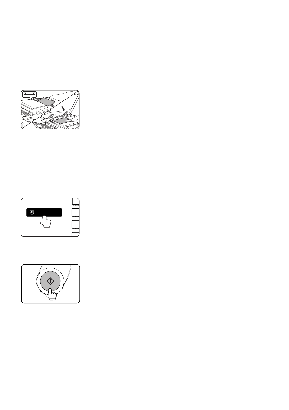
Place the first section originals in the document
3
feeder tray. (page 7)
Make all other desired settings such as the
4
number of copies, and press the [START] key.
Scanning of originals will
start. After scanning of the
first section of originals (“A
in the example above) is
completed, remove the
scanned originals, place
the next section of originals
(section B in the example)
and press the [START] key.
Repeat this operation until
all blocks of originals have
been scanned.
Touch the [READ-END] key after the last section
5
of originals has been scanned.
24
To cancel the job build function, touch the [JOB BUILD]
key on the special modes screen as in step 1. The
highlighted display will be canceled.
Page 27
MULTI SHOT
2in1 4in1
LAYOUT
Copies
One-sided copies from
one-sided originals
One-sided copies from
two-sided originals
PLACE NEXT ORIGINAL. PRESS [START].
WHEN FINISHED, PRESS [READ-END].
READ-END
SPECIAL FUNCTIONS
Multi shot
The multi shot function is used to copy up to four originals, collectively in a specified order, per sheet of copy paper in
any one of four layout patterns.
[Example] Copying seven originals using the 4 in 1 MULTI SHOT selection in a layout pattern starting from the upper
left to lower right.
●
When using the multi shot function, place the originals,
select the desired paper size, and select the copying
mode (page 9) before selecting the multi shot function
on the special modes screen.
●
When using the multi shot function, the appropriate
copy ratio will be automatically set based on the original
size, paper size, and the number of originals to be
copied onto one sheet. The minimum reduction ratio
is 25%. Depending on the original size, paper size,
and the number of originals to be copied onto one
sheet, the appropriate copy ratio may be smaller than
25%. In this case, portions of original images may not
be copied.
Touch the [MULTI SHOT] key on the SPECIAL
1
MODES screen.
Select the number of originals to be copied onto
2
one sheet of copy paper on the multi shot
selection screen.
Select the layout.
3
The multi shot setting
screen will appear.
The orientation of copy
paper and the image of the
originals may be rotated as
needed.
Select the order in which
the originals will be
arranged on the copy.
[When using the automatic document feeder:]
4
Copying will start after all originals have been scanned.
(The next step is not needed.)
[When using the document glass:]
Replace the original with the next original and press
the [START] key. Repeat this operation until all originals
have been scanned.
If scanning is being done from the document
5
glass, touch the [READ-END] key after the last
original has been scanned to start copying.
To cancel the multi shot function, touch the [CANCEL] key
on the multi shot setting screen.
25
Page 28
JOB PROGRAM MEMORY
5
1
M NUMBER.
STORE
/
DELETE
234
789
1
6
RECALL
ESS PROGRAM NUMBER.
PROGRAMS
STORE
/
234
789
TO STORE, MAKE SELECTIONS AND PRESS [OK],
TO DELETE, PRESS [CANCEL].
SPECIAL MODES
2-SIDED COPY
OUTPUT
8
1
2
/
11
X
8
1
2
/
11
X
8
1
2
/
11
X
11 17
x
8
1
2
/
11R
X
1.
2.
3.
4.
EXPOSURE
AUTO
AUTO
100%
OK
8
1
2
/
11
X
11
8
1
2
/
11
X
8
1
2
/
11
X
11 17
x
8
1
2
/
11R
X
1.
2.
3.
4.
D PRESS [OK].
PAPER SELECT
COPY RATIO
CANCEL
Frequently used job programs can be stored in each of ten storage registers. This is convenient for quick job recall
without losing time manually reprogramming each aspect of a job.
●
Selection for functions stored as part of a job program, will not be recalled as part of the program if the function has
been disabled or changed by a key operator program.
●
To exit the job memory mode, press the [CA] (clear all) key on the operation panel or touch the [EXIT] key on the
touch panel.
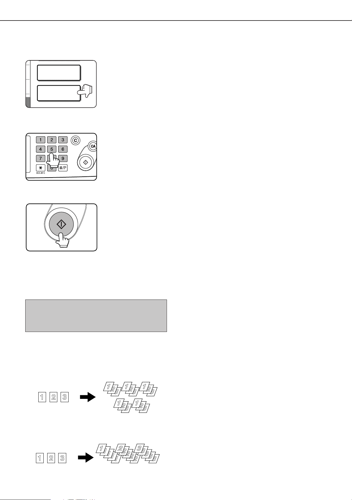
Storing a job program
Press the [#/P] key on the operation panel to
1
display the [STORE/DELETE] selection screen.
Touch the [STORE/DELETE] key to obtain the
2
storage register screen.
Touch a number key from 1 to 10 on the storage
3
register screen.
Highlighted storage
register numbers are
registers which already
have programs stored. If a
highlighted number is
selected, a screen will
appear with selections for
deleting the selected
program, storing (replacing
the selected program with
a new one) or canceling to
go back to the STORE/
DELETE screen to select a
different storage register.
Make all copier selections to be stored.
4
The number of copies
cannot be stored.
Touch the [OK] key.
5
The selected settings will
be stored under the register
number selected in step 3.
26
Page 29
Recalling a job program
1
6
2
7
3
8
RECALL
PRESS PROGRAM NUMBER.
JOB PROGRAMS
5
10
3
8
4
9
EXIT
STORE
/
DELETE
REC LL
STORE/DELETE
A JOB PROGRAM HAS BEEN ALREADY STORED.
STORE ANOTHER PROGRAM?
CANCEL DELETE STORE
Press the [#/P] key.
1
Touch the desired storage register number key
2
to recall the job from memory.
When a number key is
touched, the selection
screen will be closed and
the stored job program will
be recalled. A number for
which no job program has
been stored cannot be
selected.
JOB PROGRAM MEMORY
Set the number of copies as needed and press
3
the [START] key.
Copying will start with the
settings of the recalled job
program.
Deleting a stored job program
Follow steps 1 and 2 in “Storing a job program”
1
on the previous page.
Select a storage register number of the program
2
to be deleted.
If a number key for which
no job program has been
stored is selected, the
screen will change to the
screen of step 4 on the
previous page (for storing
a program). The message
“TO STORE, SELECT AND
PRESS [OK]. TO DELETE,
PRESS [CANCEL].” will
appear. When [CANCEL] is
pressed, the screen will
return to the selection
screen shown to the left.
Touch the [DELETE] key.
3
When the [DELETE] key is
touched, the screen in step
2 will return and the
program will be deleted. If
the [CANCEL] key is
touched, the screen in step
2 will return but the program
will not be deleted. If no
other programs are to be
deleted, touch the [EXIT]
key on the screen displayed
in step 2 to exit the job
program mode.
27
Page 30
INTERRUPTING A PRINT OR COPY RUN
8
1
2
/
11
X
AUTO
0
AUTO
100
%
8
1
2
/
11
X
INTERRUPT
EXPOSURE
PAPER SELECT
CANCEL
0
AUTO
TO
100
%
8
1
2
/
11
X
1
INTERRUPT can be used to temporarily stop a long print or copy job so that another copy job can be run. Only copy
jobs can be run during interrupt.
Place the original in the document feeder tray
1
or on the document glass. (page 7)
Touch the [INTERRUPT] key.
2
When it is possible to interrupt
a print or copy job in progress,
the [INTERRUPT] key will
appear as shown in the
illustration.
When the [INTERRUPT]
key is touched in step 2, the
[INTERRUPT] touch key will
be replaced by the
[CANCEL] key as shown in
the illustration. To cancel
interrupt copying at any
time, touch the [CANCEL]
key.
Make all other desired settings such as
3
exposure, paper size and number of copies and
then press the [START] key.
■ When step 3 is completed, a copy job icon will appear
at the top of the job icon queue at the left side of the
screen and interrupt copying will start. After the
interrupt job is completed, the interrupted job will
automatically resume.
28
Page 31

MISFEED REMOVAL
Document feeding area
cover
Misfeed in scanner module
When an original has misfed in the scanner module, remove the misfed original following the procedure below.
NOTES
●
For misfeed removal in the main unit and other peripheral devices, see the “Operation manual (for printer operation and
general information)”.
●
If you press the [INFORMATION] key, detailed information for misfeed removal will be displayed on the touch panel.
Open the document feeding area cover and
1
remove any misfed originals.
Close the document feeding area cover.
2
Close the cover securely so
that cover clicks into place.
Open the document cover and turn the green
3
rotating knob in the direction of the arrow to
remove any misfed originals.
■ A message may appear indicating the number of
originals which must be returned to the document
feeder tray. Return the originals to the document feeder
tray and press the [START] key.
Close the document cover.
4
29
Page 32

TROUBLESHOOTING
Whenever the machine stops or operation is not possible, check the operation panel display for messages. In most
cases, these messages will give sufficient information to return the machine to an operating condition. In cases where
this information is not enough, check the list below for more inf ormation. This section describes problems concerning
copier features. F or troubleshooting specific problems related to printer , facsimile , or network scanner features, see the
separate manuals provided for them. For problems related to other peripheral devices, see chapter 5 of the “Operation
manual (for printer operation and general information)”.
Problem
Machine does not
operate.
Copies are too
dark or too light.
Smudges appear
on copies.
Image cannot be
rotated.
Part of original
image is not
copied.
Blank copies
Order of copies
incorrect
Job cancelation
needed
Scanning of
originals is
incomplete.
Check Solution or cause
●
Is the START key indicator off?
●
Is the original image too dark or too
light?
●
Is the exposure mode set to A UTO?
●
Is the exposure mode set to PHO TO?
●
Document glass or document
transport area dirty?
●
Black stripes on copies when the
document feeder is used?
●
Original smudged or blotchy?
●
Is the auto paper select or auto
image function set?
●
Is the original positioned correctly?
●
Is the copy ratio proper for the original
and paper sizes?
●
Is the original placed face down?
●
Is the order of originals correct?
●
Is a message requesting cancelation
of job displayed?
●
Is a message indicating memory is
full displayed?
If the indicator is not on, the machine may be
warming up. Warm-up should be completed in
approximately 80 seconds.
Adjust the exposure in the manual mode. (See page
15.)
The exposure level in the AUTO mode can be
adjusted using a key operator program. Contact your
key operator . (See page 33.)
Cancel the PHOT O exposure mode. (See page 15.)
Clean regularly . (See page 4-12 of the “Operation
manual (for printer operation and general
information)”.)
Clean the original scanning window. (See page 4-12
of the “Operation manual (for printer operation and
general information)”.)
Use a clean original.
Rotation copy functions only if the machine is either
in the auto paper select mode or in the auto image
mode. (See pages 8 and 16.)
Set the original properly . (page 7)
Use the auto image function to select the
appropriate copy ratio based on the original and
copy sizes. (See page 16.)
Place the original face down in the document feeder
tray or on the document glass. (See page 7.)
When using the document glass, set the originals
from the first page one sheet at a time.
When using the automatic document feeder, set
the originals with the first page down.
Press the [CA] (clear all) key to cancel the current
job.
If the data amount exceeds the limit when using
the pamphlet copy or multi shot copy which requires
scanning of all originals, scanning will be canceled
and copying will not be performed. If you install a
hard disk drive, the storage capacity will increase.
30
Page 33

SPECIFICATIONS
Copier
Resolution Scan: 600 dpi or 300 dpi, output: 600 dpi
Gradation Scan: 256 levels, output: 2 levels
Originals Sheets, bound documents
Maximum size: 11" x 17" or A3
Copy sizes Max. 11" x 17" or A3, min. 5-1/2" x 8-1/2" or A5
Image loss: Max 21/64" or 8 mm (leading edge and trailing edge in total), max. 21/
64" or 8 mm (along all other edges in total)
Warm-up time Approx. 80 seconds
First-copy time* 35 copy/min. type: 5.3 seconds
45 copy/min. type: 4.6 seconds
*P aper is fed from paper tra y 1, quick scan from document glass (page 33) is set,
the original scanning resolution on the document glass is set to 600 x 300 dpi
and no optional hard disk drive is installed.
Copy ratio V ariable: 25 to 400% in 1% increments , total 376 steps
Fixed presets: 25%, 64%, 77%, 100%, 121%, 129%, and 400% for inch system,
25%, 70%, 81%, 86%, 100%, 115%, 122%, 141%, and 400% for AB system
Continuous copy 999 copies; subtractive counter
Copying speed 35 copy/min. type
11" x 17" or A3 17 copies/min.
8-1/2" x 14" or B4 20 copies/min.
8-1/2" x 11" or A4 35 copies/min.
8-1/2" x 11"R or A4R 25 copies/min.
Copying speed 45 copy/min. type
11" x 17" or A3 20 copies/min.
8-1/2" x 14" or B4 22 copies/min.
8-1/2" x 11" or A4 45 copies/min.
8-1/2" x 11"R or A4R 30 copies/min
Scanner module
Name B/W scanner module/DSPF
Type T w o-side simultaneous scanning system from the document feeder .
One-sided scanning from the document glass
Original feed system Automatic continuous feeding
Original exit system Face down output
Original transport system DSPF: sheet through type (reference position: center), document glass: reference
position is left rear
Original setting direction Face down
Original sizes 5-1/2" x 8-1/2" to 11" x 17" or A5 to A3
Original weight 14 to 34 lbs. or 50 to 128 g/m
Capacity Up to 50 sheets (30 sheets*1 for 8-1/2" x 14" or B4 or larger originals) provided the
total aggregate thickness does not exceed 1/4" or 6.5 mm (14 to 20 lbs. or 50 to 80
g/m2) or 3/16" or 5 mm (21 to 34 lbs. or 80 to 128 g/m2)
P ower supply Drawn from the main unit
Dimensions 31-13/16" (W) x 24-3/8" (D) x 7-3/32" (H) or
808 mm (W) x 619 mm (D) x 180 mm (H)
Weight Approx. 43 lbs. or 19.5 kg
*1 For paper heavier than 28 lbs. (105 g/m
image can not be scanned properly and scanned image can be expanded compared with original itself.
2
), only a stack of up to 15 sheets can be set. If 16 or more sheets are set,
2
31
Page 34

KEY OPERATOR PROGRAMS
This section describes all key operator programs relating only to the copier and facsimile functions. For the key
operator programs which relate to copier , printer and facsimile functions, see the separate K e y Operator’ s Guide.
Key operator program list
Program name Pa ge
Copy function settings
Initial status settings 33
Exposure adjustment 33
Rotation copy setting 3 3
Auto paper selection setting 3 3
600dpi x 600dpi scanning mode 33
Quick scan from document glass 3 3
Device control
Original size detector setting 3 4
Disabling of document feeder 34
Using the key operator programs
T o use of the k ey operator programs , follow the procedures described in the K ey Operator’ s Guide on page 6. Also read
“Supplementary explanation of key operation for key operator programs” on page 6.
32
Page 35

Setting programs
This section describes the setting of programs common
to copier, facsimile and network scanning features. For
programs dedicated to facsimile, network scanning and
programs common to both the copier and printer features,
see their respective manuals.
Copy function settings
The following programs can be set in “Copy function
settings”.
●
Initial status settings
●
Exposure adjustment
●
Rotation copy setting
●
Auto paper selection setting
●
600dpi x 600dpi scanning mode
●
Quick scan from document glass
KEY OPERATOR PROGRAMS
Initial status settings
The copier settings will be reset when the main switch
is turned off, when the [CA] key is pressed or when
the auto clear interval has elapsed. Use this program
to establish new initial settings or to return the initial
settings to the factory default settings. Paper tray,
exposure mode, copy ratio, duplex mode, and output
mode default settings can be made.
NOTE
If a duplex mode other than 1-sided to 1-sided is set as
the default and either the duplex or scanner mode is
disabled*, the default will change to the 1-sided to 1-sided
mode.
* Disable duplex unit (page 10 of the Key Operator’s Guide)
* Disabling of document feeder (page 34)
Exposure adjustment
Use this program to lighten or darken copies in the
automatic exposure mode. The factory setting is “5”.
“1” indicates lighter density and “9” indicates darker
density on the touch panel.
Rotation copy setting
If this program is set, the image of originals will rotate
when the orientation of the originals does not match
that of the copy paper.
(Rotation copy will function only if the auto paper
select or auto image mode has been selected.)
Auto paper selection setting
Use this program to set the paper type* for the auto
paper select mode to “Plain paper” or “Plain paper
and recycle paper”.
* Paper type specified in Tray setting of the custom
setting function (page 1-20 of “Operation manual
(for printer operation and general information)”)
600dpi x 600dpi scanning mode
Use this program to change the original scanning
resolution of the automatic document feeder from
600 x 300 dpi to 600 x 600 dpi.
If this mode is set, the copy quality for fine
characters and fine lines will be improved but the
original scanning speed will be slower.
NOTE
If the original scanning speed is more important than higher
resolution, do not set this program.
Quick scan from document glass
Use this program to change the original scanning
resolution on the document glass from 600 x 600dpi
to 600 x 300 dpi.
If you set this program, the first copy time will be
shorter but the copy image will become a little more
coarse.
NOTE
If the copy image quality is more important than first copy
time, do not set this program.
NOTE
For copying from 5-1/2 x 8-1/2 or A5 size originals onto 51/2 x 8-1/2R or A5R paper, this program must be set.
33
Page 36

KEY OPERATOR PROGRAMS
Device control
Original size detection and disabling of the document
feeder can be set.
Original size detector setting
This program is used to select the group of original
sizes to be detected. Original size detection from
the document glass can be disabled using the
program CANCEL DETECTION AT DOCUMENT
GLASS.
Detectable original sizes
Group
1 INCH - 1 8-1/2 x 11, 8-1/2 x 11R, A4
2 INCH - 2 8-1/2 x 11,8-1/2 x 11R, A4
3 AB - 1 A3, A4, A4R, A5, 8-1/2 x 11,
4 AB - 2 A3, A4, A4R, A5, 8-1/2 x 11,
Document feeder tray (for automatic document feeding)
Document glass
11 x 17, 8-1/2 x 14,
5-1/2 x 8-1/2
11 x 17, 8-1/2 x 13,
5-1/2 x 8-1/2
B4, B5, B5R 216 x 330
B5, B5R, 216 x 330 B4
If CANCEL DETECTION AT DOCUMENT GLASS
is set, originals will be regarded as EXTRA for all
copier functions and no original size will be displayed.
Disabling of document feeder
This program is used to prevent use of the automatic
document feeder when the scanner module
malfunctions. In this case scanning can still be done
off the document glass.
34
Page 37

Page 38

Operation manual for copier
SHARP ELECTRONICS CORPORATION
Sharp Plaza, Mahwah, New Jersey 07430-2135.
SHARP CORPORATION
PRINTED IN CHINA
2001D KS1
TINSE2077FCZZ
P350,P450,3500,3501
3551,4500,4501,4551
Page 39

LASER PRINTER
Operation Manual
(for network scanner)
Be sure to become thoroughly familiar with this manual to gain
the maximum benefit from the product.
Before installing this product, be sure to read the installation
requirements and cautions sections of the "Operation manual
for printer operation and general information".
Be sure to keep all operation manuals handy for reference
including this manual, the "Operation manual for printer
operation and general information" and operation manuals for
any optional equipment which has been installed.
Page 40

Page 41

INTRODUCTION
The optional Network Scanner Expansion Kit (AR-NS2) enables the machine to be used as a network scanner. Page
2 of the manual that accompanies the Network Scanner Expansion Kit (AR-NS2) contains an overview of the network
scanner functions, general considerations, and an explanation of image sending methods. Please read the manual
that accompanies the AR-NS2 before you read this manual. Both manuals e xplain only the network scanner functions
of the product. F or information on loading paper, replacing toner cartridges, clearing paper misfeeds, handling peripheral
units, and other printer-related information, please refer to your "Oper ation manual (for printer operation and general
information)".
Additional manuals have been pro vided f or cop y and f acsimile f eatures. Please refer to these as necessary .
To enable the network scanner function of this machine, a product key (password) must be entered using a key
operator program. This is only required once . Use the "Product K ey Entry for Network Scanner Expansion Kit" program
to enter the product key. If you do not know your product key, please ask your dealer. (For information on using key
operator programs, ref er to "Operation manual (f or printer operation and general inf ormation)".)
NOTES
• Before using the network scanner feature, several settings must be established from the Web page. These settings are
explained from page 2 on. The settings must be established by the network administrator. Such settings must be effected by
the system administrator who has the special network related backgrounds.
• This manual assumes that several options have been installed.
TABLE OF CONTENTS
Page
INTRODUCTION...................................................... 1
SETTINGS AND PROGRAMMING REQUIRED
FOR THE NETW ORK SCANNER FEATURE ........... 2
●ABOUT THE WEB P AGE.................................... 2
●SETTING P ASSW ORDS .................................... 2
●
BASIC SETTINGS FOR NETWORK SCANNING
●SETTING UP DESTINATION INFORMA TION.... 4
●STORING SENDER INFORMATION.................. 5
●STORING A CUST OM DIRECTORY.................. 5
CONDITION SETTING SCREEN
OF SCANNER MODE .............................................. 6
SENDING AN IMAGE............................................... 8
●BASIC TRANSMISSION METHOD .................... 8
●TRANSMISSION METHODS
FOR SCAN TO E-MAIL (MANUAL
ENTRY, BROADCAST TRANSMISSION)......... 10
●SCANNING AND TRANSMITTING
A TWO-SIDED ORIGINAL ............................... 11
SCANNING SETTINGS
(ORIGINAL SIZE, RESOLUTION, EXPOSURE
AND FILE FORMAT) .............................................. 12
●
MANUALLY SETTING THE SCANNING SIZE
●SELECTING THE RESOLUTION..................... 13
●SELECTING THE EXPOSURE ........................ 14
●SELECTING THE FILE FORMAT..................... 15
..... 3
... 12
Page
PRIORITY TRANSMISSION OF A ST ORED JOB
CANCELING AN E-MAIL/FTP TRANSMISSION .... 16
STORING, EDITING, AND CLEARING
FROM THE TOUCH P ANEL ................................... 17
●STORING ONE-T OUCH KEYS
(only addresses for Scan to E-mail
and Internet-Fax).............................................. 17
●
EDITING AND DELETING ONE-TOUCH KEYS
●PROGRAMMING A GROUP KEY.................... 20
●EDITING AND DELETING GROUP KEYS....... 21
●STORING SENDER INFORMATION................ 22
●EDITING AND DELETING
SENDER INFORMA TION................................. 22
●STORING A GROUP INDEX............................ 23
●PRINTING PROGRAMMED INFORMATION ... 23
TROUBLESHOOTING............................................ 24
●IF YOUR E-MAIL IS RETURNED ..................... 24
●IF A TRANSMISSION ERR OR OCCURS ........ 24
KEY OPERATOR PROGRAMS .............................. 25
●KEY OPERATOR PROGRAM LIST.................. 25
●USING THE KEY OPERATOR PROGRAMS.... 25
●SETTING PROGRAMS.................................... 26
●PRINTING OUT SETTINGS............................. 27
SPECIFICATIONS .................................................. 28
.... 16
..... 19
1
Page 42

SETTINGS AND PROGRAMMING REQUIRED
FOR THE NETWORK SCANNER FEATURE
T o use the Network Scanner feature, settings f or the E-mail server, DNS server , and destination addresses must be established.
To establish the settings, use a computer that is connected to the same network as the machine to access the
machine's Web page. The Web page can be displayed with your Web browser (Internet Explorer 4.0 or later, or
Netscape Navigator 4.0 or later). To access the Web page , refer to page 2-6 of "Operation manual (for printer operation
and general information)".
ABOUT THE WEB PAGE
When you access the Web page in the machine, the following page will appear in your browser.
A menu frame appears on the left side of the page. When y ou clic k an item in the menu, a screen appears in the right
frame that allows you to establish settings for that item.
For overviews of each of the menu items, refer to pages 2-7 to 2-8 of "Operation manual (for printer operation and
general information)".
For detailed explanations of the procedures for establishing settings, click "Help" in the menu frame.
Web Page
SETTING PASSWORDS
Passwords can be set to restrict Web page access and protect settings.
Note that it is not necessary to set passwords; the network scanner functionality can also be used without pass words.
A password can be set for the administrator and passwords can be set for each user. If you use a user password to
access the W eb page, you will be able to estab lish, edit, and delete destinations in the Scanner Destination Management
menu; howev er, you will not be able to establish settings in the Setup menu.
The passwords f or "User" and "admin" are both initially set to "Sharp". If y ou wish to change the pass words when first
establishing the settings, enter "Sharp" in "Old Admin Passw ord" before you establish the settings. A password must
consist of alphanumeric characters and be no more than seven characters long. Passwords are case sensitive.After
entering a password, click "Submit" to set it. After setting the password, turn the machine power off and then back on.
When a password is set, you will be prompted for the password when you attempt to access a Web page with
protected settings. For the "User name", enter "user" if you are accessing the page as a user, or "admin" if you are
accessing the page as an administrator. For detailed information on setting passwords, refer to "Help".
2
Page 43

SETTINGS AND PROGRAMMING REQUIRED FOR THE NETWORK SCANNER FEATURE
BASIC SETTINGS FOR NETWORK SCANNING
Click "Network Scanning" in the menu frame, and then establish the required settings. These settings should only be
established by the network administrator. After entering the settings, be sure to click "Submit" to store them. For
detailed information on setting procedures, refer to "Help".
Network Scanning Setting screen
■■
■ Select the method for assigning a file name to a scanned image
■■
Select the method for assigning a file name to a scanned image. In "File Naming", click the items that you wish to
use in the file name. "Sender Name" and "Date & Time" are initially selected. If y ou are going to send images to the
same recipient more than once, we recommend that you also select "Session P age Counter" or "Unique Identifier"
to prevent sending multiple files with the same name, which would result in each successive file overwriting the
previous file.
■■
■ Selecting an e-mail subject (only used for Scan to E-mail)
■■
Enter a subject when using Scan to E-mail. Only one subject can be entered. If nothing is entered, “Scanned
image from <Device Name>” will appear.
*The name that appears in <Device Name> is the name stored in "Name" in the screen that appears when you click "Status
& Alert E-mail" in the menu frame. If a name has not been stored, the product name will appear.
■■
■ E-mail Server and DNS Server Settings
■■
E-mail sent by Scan to E-mail or Scan to FTP (Hyperlink) uses SMTP. To use either of these transmission methods,
you must first click "Network Settings" in the Web page menu, clic k "E-mail" in the screen that appears, and then enter
the required information in the settings under "E-mail Setup".
If you entered a host name in "Primary E-mail Server" or "Secondary E-mail Server" under "E-mail Setup", you will
need to click "DNS" and then enter the settings for the DNS server under "DNS Setup".
If you entered a host name in "Hostname or IP Address" when storing a destination for Scan to FTP (Scan to FTP
(Hyperlink)) or Scan to Desktop, you will also need to enter the settings for the DNS server under "DNS Setup".
3
Page 44

SETTINGS AND PROGRAMMING REQUIRED FOR THE NETWORK SCANNER FEATURE
SETTING UP DESTINATION INFORMATION
To store the name and address of a destination in an auto dial key, click "Destination Management" or one of the
transmission methods in the Web page menu frame. "Destination Management" can also be used to edit or clear
stored destinations.
A total of 500 destinations can be stored, including E-mail, FTP, Desktop, Internet-Fax, and Group destinations.
Among these, a combined total of 100 Scan to FTP and Desktop destinations can be stored.
The stored destinations appear as one-touch keys in the touch panel of the machine when you send an image,
allowing you to select the destination.
For detailed info rmation on setting up, editing, and deleting destinations, refer to "Help".
■■
■ Storing destinations for Scan to E-mail and Internet-Fax
■■
Scan to E-mail and Internet-Fax destinations can also be stored, edited, and cleared from the touch panel of the
machine. (Pages 17 - 19)
To perform Scan to E-mail, the e-mail server settings must first be established. (Refer to page 3.)
■■
■ Storing destinations for Scan to FTP
■■
If you select the "Enable Hyperlink to FTP server to be e-mailed" checkbox, you can send an e-mail message to
a "Sender" selected from "E-mail Destination" (stored in "Sender E-mail" in the Web page menu (page 5)), to
notify that person of the location of the scanned image data and its file format. (Scan to FTP (Hyperlink))
The e-mail includes a link to the location of the scanned image data, and if the FTP server does not require a user
name or password (anonymous server), the recipient can display the image by simply clicking on the address.
If you entered a host name in "Hostname or IP Address", you will need to enter the DNS server or WINS server
settings. Click "Network Settings" and enter the settings under "DNS Setup". To perform Scan to FTP (Hyperlink),
you must also click "E-mail" and then enter the settings under "E-mail Setup" f or the e-mail server . (Refer to page
3.)
■■
■ Storing destinations for Scan to Desktop
■■
Scan to Desktop can only be used if Network Scanner Tool is installed in your computer (Network Scanner Tool is
included on the CD-ROM that accompanies the AR-NS2 Network Scanner Expansion Kit).
You can store a Scan to Desktop destination in the Web page, or in Network Scanner Tool. We recommend that
you normally use Network Scanner Tool, which automatically establishes settings. The Web page is primarily used
when the same settings are to be established in multiple laser printers, or when the network administrator performs
maintenance. If the information set here differs from the information set in the host computer, transmission and
reception will not take place normally. For details, refer to "User's Guide"* for Network Scanner Tool in the CDROM that accompanies the Network Scanner Expansion Kit (AR-NS2).
If you entered a host name in “Hostname or IP Address”, you will need to enter the DNS server or WINS server
settings. (Refer to page 3.)
* To view "User's Guide", Adobe Acrobat Reader 4.05 or later is necessary. If this is not installed on your computer, you can
install it from the CD-ROM that accompanies the Network Scanner Expansion Kit (AR-NS2). For details, ref er to the operation
manual for the Network Scanner Expansion Kit (AR-NS2).
■■
■ Storing Groups
■■
If you are using Scan to E-mail or Internet-Fax, a scanned image can be sent to multiple destinations in a single
operation. To use this function, you must first store the destinations in a group. Click "Group" and then select the
Scan to E-mail or Internet Fax destinations that you wish to store in the group. Up to 300 destinations can be
stored in one group. Only destinations for E-mail or Internet-Fax can be stored in a group. Note that multiple
destinations cannot be entered manually when sending an image.
4
Page 45

SETTINGS AND PROGRAMMING REQUIRED FOR THE NETWORK SCANNER FEATURE
■■
■ Items common to all transmission methods when storing destinations
■■
• Full Name, Display Name
Only alphabetical characters and symbols can be used to enter names in "Full Name" and "Display Name". For
the maximum number of characters that can be entered, click "Help" in the menu frame. "Display Name" is the
one-touch key name that is displa yed in the touch panel of the machine. If a display name is not stored, the first 18
characters of the name stored in "Full Name" are automatically used as the display name.
• Initial, Custom Directory
Stored destinations are arranged on "indexes" when displayed in the touch panel of the machine. There are two
types of indexes: the ABC index and group indexes. The ABC index arranges destinations based on the letter
entered in "Initial", which is normally the first letter of the name entered in "Full Name". If a destination is frequently
used, it is convenient to select the "Frequently Used" checkbox to include the destination in the alphabetical
"FREQUENT USE" index. Group indexes ("Custom Directories") allow you to create and name indexes (see the
following page) of destinations for specific purposes.
• File Format
When you store a destination, you can also select the compression mode and the f o rmat of the image file that is
created when you scan an original for transmission. You can select TIFF-F, TIFF, or PDF for the file type, and MH
(G3), MMR (G4), or "Uncompressed" for the compression mode. An initial setting has been made for the file type
and compression mode, so you only need to make a selection if the initial settings are not satisfactor y. For an
explanation of the initial settings of each of the transmission methods, click "Help" in the menu frame.
NOTE
Internet-Fax only has one file format, TIFF-F, and thus there is no selection. MH (G3) or MMR (G4) can be selected f or the
compression mode.
STORING SENDER INFORMATION
To store the sender information (Sender Name, E-mail Address) that is displayed when the recipient receiv es y our email, click "Sender E-mail" in the menu frame and then click "Add". Information for up to 20 different senders can be
stored. Select a sender from the stored senders using the touch panel of the machine when y ou send an image (page
8). The selected sender appears in the sender column of the recipient's e-mail software program.
NOTE
If you do not select a sender when sending an image, the default sender information stored with the key operator program is
automatically sent. (Page 27)
STORING A CUSTOM DIRECTORY
Auto dial ke ys (one-touch k e ys and group k e ys) are normally stored in the ABC index. However, you can also use the
group indexes (custom directory) to group destinations for more convenient use. Six indexes are available, and a
name up to 6 characters long can be assigned to each index.
Click "Custom Directories" in the menu frame of the Web page, and then enter the desired name in the screen that
appears. "User-*" is initially entered for the name of each index. Clear this and then enter the new name.
The procedure for storing auto dial numbers in a group index is e xplained on page 4, and the procedure f or s witching
between the ABC index and the group indexes is explained on page 7.
NOTE
You can also store indexes in the Custom Directory from the touch panel of the machine.
5
Page 46

CONDITION SETTING SCREEN OF SCANNER MODE
The condition setting screen of scanner mode is displayed by pressing the IMAGE SEND key (refer to page 4 of
"Operation manual (for copier)") while the print mode, cop y mode, or job status screen appears in the touch panel. In
the explanations that follo w, it is assumed that the initial screen that appears after pressing the IMAGE SEND key is
the condition setting screen (shown below). If you ha ve set the displa y to show the address directory (following page)
when the IMAGE SEND ke y is pressed, touch the CONDITION SETTINGS key in the address directory to display the
condition setting screen.
The key operator progr am can be used to set the display to show either the condition setting screen (shown belo w) or
the address directory screen (following page) when the IMAGE SEND ke y is pressed (refer to page 26).
NOTE
For information on the parts of the unit and the operation panel that are used for network scanning, refer to pages 3-4 of
"Operation manual (for copier)". F or parts that are used for both network scanning and printing, refer to chapter 1 of "Operation
manual (for printer operation and general information)".
■■
■ Condition setting screen
■■
The display is initially set (factory setting) to show the f ollo wing condition setting screen as the initial screen.
READY TO SEND.
AUTO
EXPOSURE
STANDARD
RESOLUTION
PROGRAMMED
FILE FORMAT
AUTO
ORIGINAL
Message display
Messages appear here to indicate the current status
of the machine. When the machine is ready to send,
an icon appears to the left.
ADDRESS DIRECTORY key (page 9)
This displays the Address Directory screen (next
page). Touch this key when you want to use an autodial number (one-touch dialing or group dialing).
ADDRESS REVIEW key (page 10)
When performing Scan to E-mail or Internet-Fax
broadcast transmission, touch this key to chec k your
selected destinations. Y our selected destinations will
appear as a list, and the list can be edited.
ADDRESS
DIRECTORY
ADDRESS REVIEW
E-MAIL ADDRESS
SENDER LIST
Two-sided scanning icon display (page 11)
Icons appear here when you touch the ORIGINAL
key and select two-sided scanning. The icons can
be touched to open function selection screens.
ORIGINAL key (pages 11-12)
Touch this key when you wish to manually set the
size of the original to be scanned or scan both sides
of the original.
FILE FORMAT key (page 15)
Touch this key to set the file format of scan images
that you transmit. The selected file format setting
will be highlighted above the key. The initial factory
setting is PROGRAMMED .
SENDER LIST key (page 8)
Touch this key to select the sender when sending
an image.
E-MAIL ADDRESS key (page 10)
When performing Scan to E-mail, touch this key if
you wish to enter the e-mail address of the recipient
manually instead of using an auto dial key.
6
RESOLUTION key (page 13)
Touch this key to change the resolution setting for
the original to be scanned. The selected resolution
setting will be highlighted above the key. The initial
factory setting is STANDARD .
EXPOSURE key* (page 14)
Touch this key to change the exposure setting for
the original to be scanned. The selected exposure
setting will be highlighted above the key. The initial
factory setting is AUT O.
Page 47

CONDITION SETTING SCREEN OF SCANNER MODE
GROUP6GROUP5GROUP4GROUP3GROUP2GROUP1
ABC GROUP
SHARP CORPORATION
FREQUENT USE ABCD EFGHI JKLMN OPQRST UVWXYZ
ABC GROUP
TPS
SHARP GROUP D DESKTOP
E F
G H DESKTOP
CONDITION
SETTINGS
READY TO SEND.
ADDRESS REVIEW
■ Address directory screen (alphabetically ordered)
If you hav e set the initial screen to the address directory screen using the key operator program, the initial screen
will appear as follows.
Destinations stored using the W eb page are grouped in indexes ( ) according to the letter entered in "Initial" for
each destination, and the name entered in "Display Name" is displayed in the one-touch key ( ).
E-mail Destination Management page
One-touch key display
This shows the one-touch keys that have been
stored on the selected "index card". The key type is
indicated by the icon at the right.
:Scan to E-mail, Internet-Fax
: Scan to FTP
: Scan to Desktop
The display is initially set to show 8 keys. This can
be changed to 6 or 12 using the key operator
program. (Refer to page 26.)
Display switching keys
In cases where the one-touch keys cannot all be
displayed on one screen, this shows how many
screens are left. Touch the " " " " keys to move
through the screens.
CONDITION SETTINGS key
This displays the condition setting screen (previous
page), which is used to set various conditions.
ABC GROUP key
Touch this key to switch between the alphabetical
index and the group index.
Index keys
One-touch key destinations are stored on each of
these index cards (alphabetical index or group
index). Touch an index key to display the card.
Group indexes make it possible to store one-touch
keys by group with an assigned name for easy
reference. This is done with the custom settings (refer
to page 5). Frequently used one-touch key
destinations can be stored on the FREQUENT USE
card for convenient access.
NOTE
The screen showed above is the alphabetical address directory. If desired, the initial screen can be set to the group address
directory (refer to page 26).
7
Page 48

SENDING AN IMAGE
AUTO 8 X11
ORIGINAL
ST ND RD
RESOLUTION
PROGRAMMED
FILE FORMAT
AUTO 8 X11
ORIGINAL
STANDARD
RESOLUTION
PROGRAMMED
FILE FORMAT
AUTO
EXPOSURE
STANDARD
RESOLUTION
PROGRAMMED
FILE FORMAT
AUTO 8 X11
ORIGINAL
STANDARD
RESOLUTION
PROGRAMMED
FILE FORMAT
ADDRESS REVIEW
DIRECTORY
2 GROUP
SHARP PPD
1 GROUP
1 GROUP
BASIC TRANSMISSION METHOD
Make sure the machine is in scanner mode.
1
When the IMAGE SEND
key light is on, the machine
is in scanner mode. If the
light is not on, press the
IMAGE SEND key.
Load the original.
2
For detailed information on
loading an original, refer to
pages 7 and 8 of "Operation
manual (for copier)".
NOTE
You cannot load documents in both the auto document
feeder and on the document glass and send them in a
single transmission. If documents are loaded in both the
auto document feeder and on the document glass, only
the document in the auto document feeder will be scanned
and transmitted.
If needed, adjust the exposure setting.
5
(Refer to page 14.)
The initial factory setting is
AUTO.
1
/
2
If needed, select the file format.
6
(Refer to page 15.)
The initial factory setting is
PROGRAMMED.
1
/
2
Touch the SENDER LIST key.
7
This step is not necessary
for Scan to FTP or Scan to
Desktop. Go directly to step
10 (next page).
Check the original size.
3
The original size is
automatically detected.
If you loaded a non-standard
size document or wish to
1
/
2
NOTE
To scan a two-sided original, refer to page 11.
If needed, adjust the resolution setting.
4
(Refer to page 13.)
1
/
2
change the scanning size,
touch the ORIGINAL key
and set the document size.
(Refer to page 12.)
The initial factory setting is
STANDARD.
NOTES
• You can omit selection of a sender (go directly to step
10). In this case, the default sender information stored
with the key operator program is automatically
transmitted. (Page 27)
• Up to 20 senders can be stored using the Web page.
(Page 5)
Touch a key to select a sender.
8
The touched key is
highlighted. If you made a
mistake, touch the correct
key. The highlighting will
move to the new key.
The selected sender will be
the sender of the e-mail.
Touch the OK key.
9
8
Page 49

SENDING AN IMAGE
ADDRESS
DIRECTORY
FREQUENT USE ABCD EFGHI JKLMN OPQRS
T.P.S.
SHARP GROUP
SHARP CORPORATION
READY TO SEND.
READ-END
L. (Pg.No. 3)
Touch the ADDRESS DIRECTORY key.
10
The address directory
screen appears.
Touch the one-touch key for the desired
11
destination.
Refer to page 7 for
information on using the
address directory screen.
The key you touched is
highlighted. If you touch the
wrong key , touch the key again
to cancel the selection. The key
display will return to normal.
NOTES
• Refer to pages 4 and 5 for information on programming
one-touch key destinations.
•
When pressing a one-touch key, corresponding information from
the email destination screen is shown in the message display. Up
to 28 characters can be displayed in the message screen,
regardless of the number of characters that have been entered.
• Y ou can also man ually enter the address of a Scan to Email destination, or select multiple destinations for a
broadcast transmission. (Next page)
Using the auto document feeder
Press the START key.
12
Using the document glass
Press the START key.
12
The original is scanned
and the READ-END key
appears.
If you have another page to scan, change pages
13
and then press the START key.
Repeat this sequence until all pages have been scanned.
You can change the resolution and exposure settings
as needed for each page (refer to pages 13 and 14).
If no action is taken for one minute, scanning
automatically ends and the transmission job is stored.
After the final page is scanned, touch the READ-
14
END key.
The machine makes a beep
sound to inform you that the
transmission job is stored
and JOB STORED appears
in the message display . (The
destination is automatically
called and the document
transmitted after previously
stored jobs are completed.)
Open the document glass cover and remove the
document.
If scanning is completed normally, the machine makes a
beep sound to inform you that the transmission job is stored
and JOB STORED appears in the message display.
NOTES
• Canceling transmission
To cancel transmission while SCANNING ORIGINAL... appears in the display or bef ore the READ-END ke y is pressed, press the C k e y or
the CA key. To cancel a transmission job that is already stored, press the JOB STATUS key and cancel the job as explained on page 16.
• Important points when using Scan to E-mail
Be very careful not to send image data files that are too large. Your mail server's system administrator may have placed a limit
on the amount of data that can be sent in one e-mail transmission. If this limit is exceeded, the e-mail will not be delivered to
the recipient. Even if there is no limit and your e-mail is successfully delivered, a large data file may take a long time to be
received and place a heavy burden on the recipient's network, depending on the recipient's network (Internet) connection
environment. If large image data files are repeatedly sent, the resulting burden on the network may slow down the speed of
other, unrelated data transmissions and in some cases, may even cause the mail server or network to go down.
In cases where you need to send multiple documents, try such measures as lowering the resolution or image quality mode.
•
If the power is turned off or a power failure occurs while a document is being scanned in the auto document feeder , the machine will stop and
a document misfeed will occur. After power is restored, remove the document as explained on page 29 of "Operation manual (for c opier)".
Scanning begins and the
transmission job is stored.
(The job is transmitted
after previously stored
transmission jobs have
been completed.)
9
Page 50

SENDING AN IMAGE
E-MAIL ADDRESS SENDER
ADDRESS
DIRECT
CANCEL OK
OK
ADDRESS REVIEW
DIRECTORY
CONDITION
SETTINGS
NEXT ADDRESS
TRANSMISSION METHODS FOR SCAN TO E-MAIL
(MANUAL ENTRY, BROADCAST TRANSMISSION)
It is possible to manually enter the address of a Scan to E-mail destination, or select multiple destinations for a
broadcast transmission. (These procedures are not possible when perf orming an Internet-Fax transmission. First use
the procedure in "Basic transmission method" on pages 8 to 9.)
Perform steps 1 through 9 of "Basic
1
transmission method" (pages 8 to 9).
Touch the E-MAIL ADDRESS key.
2
Enter the e-mail address.
3
If you make a mistake , press the key to move the cursor
(
■
) back to the mistake and then enter the correct
character.
Touch the FILE FORMAT key.
4
NOTE
The initial file format setting can be changed with the key
operator program. (Page 27)
Select the file type and the compression mode.
5
E-MAIL ADDRESS
FILE FORMAT
PDF
TIFF-F
The file format is initially set
to "File type: PDF,
Compression mode: MMR
(G4)". If you do not need to
change the file format, go
directly to step 6.
CANCEL OK
FILE TYPE COMPRESSION MODE
TIFF
NONE
MMR (G4)
MH (G3)
Touch the outer OK key.
6
You will return to the initial
screen.
If you are not performing a
broadcast transmission, go
directly to step 9.
If you wish to enter another e-mail address,
7
repeat steps 2 through 6.
NOTES
• If the key operator
program has been set
so that the NEXT
ADDRESS key must
always be pressed
(page 26) and you wish
to enter another
address, press the
NEXT ADDRESS key and then repeat steps 2 through 6.
• If you frequently use broadcasting to send documents to
the same group of destinations, it is convenient to program
those destinations into a group key. (Page 4)
Touch the ADDRESS REVIEW key and check the
8
destinations.
When the ADDRESS
REVIEW key is pressed,
only the entered
destinations are displayed.
If you need to clear a
destination, press its key.
Press the OK key to return
to the initial screen.
Continue from step 12 of "Basic transmission
9
method" (pages 8 to 9).
NOTES
• To cancel a broadcast transmission when selecting
OK
destinations, press the CA key.
• When you perform a broadcast transmission, the
compression mode set with the key operator program is
used as the file compression mode for all destinations.
This is initially set to "MH (G3)". If desired, you can change
the setting to "MMR (G4)". (Page 27)
10
Page 51

SENDING AN IMAGE
AUTO 8 X11
ORIGINAL
RESOLUTION
PROGRAMMED
FILE FORMAT
AUTO MANUAL
2-SIDED
BOOKLET
2-SIDED
TABLET
ORIGINAL SIZE
OK
ORIGINAL
ST ND RD
RESOLUTION
PROGRAMMED
FILE FORMAT
SCANNING AND TRANSMITTING A TWO-SIDED ORIGINAL
A two-sided original can be automatically scanned and transmitted using the auto document feeder . F ollow the steps
below.
Make sure the machine is in scanner mode and
1
then load the document in the auto document
feeder.
Touch the ORIGINAL key.
2
When you touch the
ORIGINAL key, check the
original size displayed in the
key .
1
/
2
Touch the 2-SIDED BOOKLET key or the 2-
3
SIDED TABLET key as appropriate for the
original you loaded.
If necessary, touch the
MANUAL key and set the
original size. (Page 12)
Touch the OK key.
4
You will return to the initial
screen.
A two-sided original icon appears next to the ORIGINAL key.
(Example: The icon that appears when the 2-SIDED
BOOKLET key is touched.)
1
AUTO 8 X11
Continue from step 4 of "Basic transmission
5
method" (pages 8 to 9).
/
2
NOTES
• Booklets and tablets
Two-sided originals that are bound at the side are booklets, and two-sided originals
that are bound at the top are tablets.
• Two-sided scanning turns off after the document is stored in memory. Pressing the
CA key will also cancel two-sided scanning.
Booklet Tablet
11
Page 52

SCANNING SETTINGS (ORIGINAL SIZE,
AUTO 8 X11
ORIGINAL
RESOLUTION
PROGRAMMED
FILE FORMAT
ROTATE THE IMAGE 90 DEGREE
MANUAL
ST
UTO
2-SIDED
TABLET
OK
OK
INCH
AB
ORIGINAL SIZE
MANUALAUTO
5 X8
1
/
2
1
/
2
5 X8 R
1
/
2
1
/
2
8 X11
1
/
2
8 X11R
1
/
2
8 X14
1
/
2
11X17
OK
OK
B4
A3
B5R
A4
A5
A5R
INCH
AB
A4RB5
ORIGINAL SIZE
MANUALAUTO
OK
OK
L
ORIGINAL
RESOLUTION
PROGRAMMED
FILE FORMAT
A4
RESOLUTION, EXPOSURE, AND FILE FORMAT)
When sending an image, you can adjust the original size, resolution, e xposure , and file f ormat settings as needed.
MANUALLY SETTING THE SCANNING SIZE
If you load an original that is not a standard size (such as an AB size), or if you wish to change the scanning size , touch
the ORIGINAL key and set the original size manually. Perform the following steps after loading the document in the
automatic document feeder or on the document glass.
NOTE
Standard sizes that can be detected are as follows:
5-1/2"x8-1/2", 8-1/2"x11", 8-1/2"x11"R, 8-1/2"x14", 11"x17". If a non-standard siz e original is loaded (including special sizes ),
the closest standard size may be displayed, or the original size may not appear at all.
Touch the ORIGINAL key.
1
1
/
2
Touch the MANUAL key.
2
ORIGINAL SIZE
The sizes that can be
selected are displayed.
NOTE
If you wish to rotate the original 90° when creating an image
file, click the "Load the original so that the image is oriented
horizontally" checkbox (a checkmark should appear in the
box).
If you wish to select an AB size, touch the
AB INCH key and then touch the desired
original size key.
AB is highlighted and AB
size keys are displayed. To
return to the inch palette,
touch the AB
once again.
Touch the outer OK key.
4
You will return to the initial
screen. (Pressing the inner
OK key in the step above
returns you to step 2.)
A4
The selected size appears in the top half of the
5
ORIGINAL key.
INCH key
3
12
Touch the desired original size key.
AUTO is no longer
highlighted. MANUAL and
the original size key you
touched are highlighted.
NOTE
You can return to automatic detection by pressing the CA key.
Page 53

SCANNING SETTINGS (ORIGINAL SIZE, RESOLUTION, EXPOSURE, AND FILE FORMAT)
AUTO 8 X11
ORIGINAL
STANDARD
RESOLUTION
PROGRAMMED
FILE FORMAT
HALF TONE
OK
L/FTP
200
300
400
600
INTERNET
FAX
200 100
200 200
200 400
400 400
(dpi)
STANDARD
FINE
SUPER FINE
ULTRA FINE
200 200
300 300
400 400
600 600
200 100
200 200
200 400
400 400
(
HALF TONE
OK
INTERNET
FAX
200 100
200 200
200 400
400 400
(dpi)
OK
SELECTING THE RESOLUTION
After loading the original, you can adjust the resolution as needed for the type of original and the size of the letters on
it. After loading the original in scanner mode, adjust the settings as explained below. The initial resolution setting is
STANDARD.
■ Change the resolution.
Touch the RESOLUTION key.
1
1
/
2
Touch the desired resolution key.
2
The selected key is
highlighted. If you selected
FINE, SUPER FINE, or
ULTRA FINE, you can also
touch the HALF TONE key
to select halftone.
Touch the OK key.
3
You will return to the initial
screen.
■ Resolution settings
Touch this key if your original consists of
Standard
Fine
Super fine
Ultra fine
Half tone
normal-sized characters (like those in
this manual).
Touch this key if your original has small
characters or diagrams. The original will
be scanned at twice the resolution of the
Standard setting.
Touch this key if your original has intricate pictures or diagrams. A higher-quality image will be produced than with the
Fine setting.
Touch this key if your original has intricate pictures or diagrams. This setting
gives the best image quality. However,
transmission will take longer than with
the other settings.
Touch this key if your original is a photograph or has gradations of color (such as
a color original). This setting will produce
a clearer image than Fine, Super fine, or
Ultra fine used alone. Half tone cannot be
selected if Standard has been selected.
NOTES
• The initial factory resolution setting is Standard. If desired,
you can change the initial setting to a different setting
using the key operator program. (Refer to page 26.)
• When using the automatic document feeder, the
resolution setting cannot be changed once scanning has
begun.
13
Page 54

AUTO
EXPOSURE
STANDARD
RESOLUTION
PROGRAMMED
FILE FORMAT
AUTO
DARK
LIGHT
ORIGINAL
OK
LIGHT
SCANNING SETTINGS (ORIGINAL SIZE, RESOLUTION, EXPOSURE, AND FILE FORMAT)
SELECTING THE EXPOSURE
After loading the original, you can adjust the contrast as needed for the darkness and type of the original. After loading
the original in scanner mode, adjust the settings as explained below. The initial e xposure setting is AUTO.
■ Change the exposure.
Touch the EXPOSURE key.
1
If the Fax Expansion Kit
(AR-FX5) has been
installed, the SPECIAL
MODES key will appear in
place of the EXPOSURE
1
/
2
Touch the desired exposure key.
2
Touch the OK key.
3
key. In this case, press the
SPECIAL MODES key and
then press the EXPOSURE
key .
The selected key is
highlighted.
You will return to the initial
screen.
■ Exposure settings
Dark Select this setting if your original consists
Original mostly of dark characters.
This setting automatically adjusts the ex-
Auto
Light Select this setting if your original consists
Original mostly of faint characters.
posure for light and dark parts of the original.
NOTE
When using the document glass to scan pages an original,
the exposure setting can be changed each time you change
pages. When using the automatic document feeder, the
exposure setting cannot be changed once scanning has
begun.
14
Page 55

SCANNING SETTINGS (ORIGINAL SIZE, RESOLUTION, EXPOSURE, AND FILE FORMAT)
AUTO 8 X11
ORIGINAL
STANDARD
RESOLUTION
PROGRAMMED
FILE FORMAT
ORIGINAL
AUTO
EXPOSURE
STANDARD
RESOLUTION
FILE FORMAT
READY TO SEND.
ONE PAGE PER FILE
AUTO 8 X11
1
/
2
TIFF
TIFF-F
PDF
MH (G3)
MMR (G4)PROGRAMMED PROGRAMMED
NONE
FILE TYPE COMPRESSION MODE
OK
MH (G3)
MMR (G4)ED PROGRAMMED
NONE
COMPRESSION MODE
OK
SELECTING THE FILE FORMAT
When you send an image to one or more recipients using Scan to E-mail or Scan to FTP, the FILE FORMAT key
enables you to temporarily ov erride the individual file format settings (FILE TYPE / COMPRESSION MODE) stored
for each recipient and send the image to all of the recipients using a single file format setting.
"PROGRAMMED" is initially selected, which means that the file format settings stored for each recipient are used.
Touch the FILE FORMAT key.
1
1
/
2
Select the file type and the compression mode.
2
NOTE
When the "ONE P AGE PER FILE" chec kbox is not selected,
all scanned pages are combined into a single file. When
the checkbox is selected, one file is created per page.
Touch the OK key.
3
You will return to the initial
screen.
NOTES
• The initial file format setting can be changed with the key
operator program. (Page 27)
• Even if you change the settings in the FILE FORMAT
setting screen, you can return to the settings stored for
each recipient by selecting "PROGRAMMED" once again.
The PROGRAMMED key returns both the file type and
compression mode to the stored file format settings
regardless of which key is touched. You cannot retur n
only the file type, or only the compression mode, to the
stored setting.
• When you perform a broadcast transmission, the
compression mode selected in the key operator progr am
has precedence over the others.
15
Page 56

E-MAIL/FTP
WAITING
WAITING
WAITING
PRIORITY
STOP/DELETE
PRIORITY TRANSMISSION OF A STORED JOB
E-MAIL/FTP
WAITING
WAITING
WAITING
PRIORITY
STOP/DELETE
If you have an urgent tr ansmission job and multiple transmission jobs hav e already been stored, you can giv e priority
to the urgent job so that it will be transmitted immediately after the job currently being ex ecuted. This is done from the
job status screen. For details on using the job status screen, refer to page 1-14 of "Operation manual (for printer
operation and general information)".
Press the JOB STATUS key.
1
Touch the E-MAIL/FTP key.
2
Touch the job key of the transmission job to
3
which you wish to give priority.
The touched key is highlighted.
Touch the PRIORITY key.
4
The selected job moves up
to the next position after the
job currently being
executed.
When the current job is completed, execution begins of
the job selected in step 3.
NOTE
If the job currently being executed is a broadcast
transmission, the priority job will be executed after the call
to the current destination is completed. When the pr iority
job is completed, the remaining broadcast destinations are
called. However, if the prior ity job is also a broadcast
transmission, the job is begun after the current broadcast
job is completed.
CANCELING AN E-MAIL/FTP TRANSMISSION
You can cancel a transmission job that is in progress or that has been stored. Cancellation is done from the e-mail/
FTP job status screen.
Press the JOB STATUS key.
1
Touch the E-MAIL/FTP key.
2
Touch the job key of the transmission job you
3
wish to cancel.
The touched key is highlighted.
Touch the STOP/DELETE key.
4
A message appears to
confirm the cancellation.
T ouch the YES k ey to delete
the selected job key and
cancel the transmission.
NOTE
If you do not wish to cancel the transmission, touch the
NO key.
16
Page 57

KEY OPERATOR PRO
ADDRESS
CONTROL
DIRECT ADDRESS
CUSTOM INDEX
INDIVIDUAL
GROUP
STORE
E-MAIL INTERNET-FAX
NAME
INDEX ADDRESS
DIRECT ADDRESS / INDIVIDUAL
NAME
INDEX FAX
E-MAIL INTER
INITIAL
FILE FORMAT
STORING, EDITING, AND CLEARING FROM
THE TOUCH PANEL
One-touch and group keys f or Scan to E-mail and Internet-Fax, group inde xes, and senders can also be stored, edited
and cleared from the touch panel of the machine.
STORING ONE-TOUCH KEYS
The touch panel of the machine can also be used to store destinations for Scan to E-mail and Internet-Fax. (Scan to
FTP destinations must be stored using the Web page, and Scan to Desktop destinations must be stored using
Network Scanner Tool (page 4).)
Press the CUSTOM SETTINGS key.
1
Touch the ADDRESS CONTROL key.
2
(only addresses for Scan to E-mail and Internet-Fax)
Touch the NAME key.
6
The "No." that automatically
appears is the lowest number
from 001 to 500 that has not
yet been programmed. When
NAME is touched, the letterentry screen appears. Enter up
to 36 characters for the name.
NOTE
If you are going to use the Web page to edit or delete the
stored name at a later time, do not use the characters ", <,
or >. These characters cannot be display ed in the Web page .
Touch the INITIAL key.
7
Touch the DIRECT ADDRESS key.
3
Touch the INDIVIDUAL key.
4
Click the checkbox of the transmission method
5
to be used so that a checkmark appears.
(Example: Scan to E-mail)
Touch a letter key.
8
The first letter (initial) of the
name entered in step 6 is
initially selected and is
highlighted. If you wish to
change the letter, touch a
different letter key.
NOTE
The initial you enter here determines the position of the
one-touch key in the ABC index. For information on the
ABC index, refer to page 7.
Touch the OK key.
9
17
Page 58

STORING, EDITING, AND CLEARING FROM THE TOUCH PANEL
NAME SHARP CORPORATION
INDEX ADDRE
KEY NAME
INTERNET
ADDRESS
FILE FORMAT
NAME SHARP CORPORATION
E-MAIL INTERNET-
REGISTRATION IS COMPLETED.
INDEX USER 3 ADDRES
KEY NAME SHARP CORPORATION
ON SINITIAL
ppd1@sharp.co.jpDDRESS
PDF / MMR (G4)FILE FORMAT
ON SINITIAL
ppd2@sharp.co.jpDDRESS
ON MH (G3)COMPRESSION
SINITIAL
NEXT EXIT
ppd1@sharp.co.jp
Touch the INDEX key.
10
E-MAIL
Touch an index key.
11
DIRECT ADDRESS / INDIVIDUAL
INDEX
SELECT THE CUSTOM INDEX WHERE YOU REGISTER THIS ADDRESS.
USER 1 USER 2
DO YOU REGISTER THIS ADDRESS AT THE [FREQUENT USE], TOO?
Select one of the upper row of keys (USER 1 through USER
6) to determine the location of the one-touch key when the
GROUP index is displa y ed instead of the ABC inde x (refer
to page 7). The lower keys are for selecting whether to
include the one-touch key in the FREQUENT USE index.
If you touch the wrong key, simply touch the correct key.
Touch the OK key.
12
Touch the ADDRESS key.
13
Enter the e-mail address of the destination.
14
USER 3 USER 4 USER 5 USER 6
YES NO
NEXT EXIT
OK
The E-mail address entry
screen appears.
Check the key name.
16
The characters appearing next to the NAME key will be
displayed in the key. Only the first 18 characters of the
name entered in step 6 will be displayed.
If you need to change the name that will be displayed in
the key, touch the KEY NAME key.
If you do not wish to change
the name, this step is not
necessary.
Check the file format and the compression
17
mode.
For a Scan to E-mail destination
Initial settings are File type: PDF, Compression mode:
MMR (G4). If you need to change these settings, touch
the FILE FORMA T ke y . File type selections are PDF, TIFF ,
and TIFF-F; and compression mode selections are
NONE, MH (G3), MMR (G4).
If you do not need to change
the settings, this step is not
necessary.
When you have completed
the settings, press the OK
key .
For an Internet-Fax destination
The initial setting is Compression mode: MH (G3). If y ou
need to change the setting, press the COMPRESSION
key. Selections are MH (G3) and MMR (G4).
If you do not need to change
the settings, this step is not
necessary.
When you have completed
the settings, press the OK
key .
Up to 64 characters can be entered.
If you make a mistake, touch the
cursor (
character.
Touch the OK key.
15
Y ou will return to the one-touch ke y programming screen.
REGISTRATION IS COMPLETED will appear
highlighted to the right of "No.".
NOTE
The "ADDRESS" line only shows 32 digits, regardless of
how many were digits were actually programmed.
18
key to move the
) back one space and then enter the correct
NOTE
The file format for Internet-Fax is automatically set to TIFF-F.
When you have finished programming the one-
18
touch key, touch the EXIT key
If you wish to program another one-touch key,
touch the NEXT key.
Pressing the EXIT key
returns you to the screen of
step 4 on the previous page.
Page 59

STORING, EDITING, AND CLEARING FROM THE TOUCH PANEL
AMEND/DELETE
SINITIAL
DELETE EXIT
SINITIAL
DELETE EXIT
DELETE THE ADDRESS?
SHARP CORPORATION
NO YES
EDITING AND DELETING ONE-TOUCH KEYS
If you wish to delete a one-touch key or change the E-mail address , name, or other information programmed in a onetouch key, perform the following procedure.
Press the CUSTOM SETTINGS key, touch the
1
ADDRESS CONTROL key, and then touch the
DIRECT ADDRESS key (refer to steps 1 to 3 on
page 17).
Touch the AMEND/DELETE key.
2
Touch the one-touch key you wish to edit or
3
delete.
DIRECT ADDRESS / AMEND/DELETE
SELECT ADDRESS TO AMEND/DELETE.
SHARP CORPORATION TPS
SHARP GROUP
FREQUENT USE
ABCD EFGHI JKLMN OPQRST UVWXYZ
EXIT
ABC GROUP
Touch the key corresponding to the information
4
you wish to change (change the information in
the same way as you stored the information on
pages 17 to 18).
DIRECT ADDRESS / AMEND/DELETE
E-MAIL
NAME SHARP CORPORATION
INDEX USER 3 ppd1@sharp.co.jpADDRESS
KEY NAME SHRAP CORPORATION PDF / MMR (G4)FILE FORMAT
Make sure that your changes are correct, and
5
then touch the EXIT key.
.
Touch the DELETE key.
6
INTERNET-FAX
DELETE EXIT
If you wish to change
another one-touch key,
repeat steps 3 through 5
SINITIAL
NOTES
• If you cannot edit or delete a one-touch key
If you attempt to edit or delete a one-touch key in the f ollowing situations , a warning message will appear and editing/deletion
will not be possible.
● The one-touch key you wish to edit or delete is currently being used for transmission or is used in a currently stored
● The one-touch key is included in a group key.
If the key is being used for a current transmission or currently stored transmission, cancel the transmission or wait until it is
completed and then change or delete the key. If the ke y is included in one of the abov e g roups, delete the k ey from the g roup
and then change or delete the key.
• Destinations for Scan to FTP and Scan to Desktop that are stored in one-touch keys cannot be edited or cleared from the
touch panel of the machine. Use the Web page to edit or clear these destinations. (Page 2)
● To edit a one-touch key, follow steps 4 and 5.
●
To delete a one-touch key, follow steps 6 and 7.
● When you have finished editing or deleting,
touch the EXIT key.
transmission job.
Touch the YES key.
7
If you wish to delete another
one-touch key, repeat steps
3, 6, and 7.
19
Page 60

INDIVIDUAL GROUP
STORE
GROUP-SHARP DIGITAL DOCUMENT
ME
STORING, EDITING, AND CLEARING FROM THE TOUCH PANEL
ABC GROUP
ADDRESS REVIEW
PROGRAMMING A GROUP KEY
Scan to E-mail and Internet-Fax destinations that hav e been stored in one-touch keys can be stored in group k eys. Up
to 300 destinations can be stored in a group key.
To program a group key from the Web page, refer to page 4.
NOTE
Only one-touch key destinations can be stored in a group key. If you wish to store a destination that is not programmed in a
one-touch key, first program the destination in a one-touch key and then store it in the group key.
Press the CUSTOM SETTINGS key, touch the
1
ADDRESS CONTROL key, and then touch the
DIRECT ADDRESS key (refer to steps 1 to 3 on
page 17).
Touch the GROUP key.
2
Follow steps 6 through 12 of "Storing one-touch
3
keys" (pages 17 to 18) to enter a GROUP NAME,
INITIAL, and INDEX.
Touch the ADDRESS key.
4
Touch index keys and the keys as
5
needed, and then touch one-touch keys of the
destinations that you wish to store in the group.
DIRECT ADDRESS / GROUP
SELECT ADDRESS.
A B
C GROUP SHARP CORPORATION
TPS
FREQUENT USE ABCD EFGHI JKLMN OPQRST UVWXYZ
ADDRESS REVIEW
ABC GROUP
To check the destinations that you have stored
6
in the group, touch the ADDRESS REVIEW key.
A list of your selected
destinations is displayed.
You can delete a displayed
destination by touching it.
When a message appears
asking if you want to delete
the destination, touch the
YES key.
Touch the outer OK key.
7
DIRECT ADDRESS / GROUP
SELECT ADDRESS TO DELETE.
GROUP NAME : SHARP GROUP
SHARP CORPORATION TPS
The number of destinations in the group appears to the
right of the ADDRESS key.
Check the name of the key (refer to step 16 on
8
page 18).
The characters appearing next to the KEY NAME key
will be displayed in the group key. To change these
characters, touch the KEY NAME key. This step is not
necessary if you do not wish to change the characters.
Touch the EXIT key when you have finished
9
programming the group key.
OK
OK
If you wish to program another group key, touch
the NEXT key.
When you touch the EXIT key, you will retur n to the
screen of step 2.
One-touch keys that hav e been touched are highlighted.
If you touch the wrong key, simply touch it again to cancel
the highlighting and remove the destination from the
group.
NOTE
One group key cannot be stored in another group key.
Group keys appear grayed out and cannot be touched.
20
Page 61

STORING, EDITING, AND CLEARING FROM THE TOUCH PANEL
AMEND/DELETE
SINITIAL
DELETE EXIT
SINITIAL
DELETE EXIT
DELETE THE ADDRESS?
SHARP GROUP
NO YES
EDITING AND DELETING GROUP KEYS
If you need to delete group ke y or change its name or one of its stored destinations, perf orm the following procedure.
Press the CUSTOM SETTINGS key, touch the
1
ADDRESS CONTROL key, and then touch the
DIRECT ADDRESS key (refer to steps 1 to 3 on
page 17).
Touch the AMEND/DELETE key.
2
Touch the group key you wish to edit or delete.
3
DIRECT ADDRESS / AMEND/DELETE
SELECT ADDRESS TO AMEND/DELETE.
SHARP CORPORATION TPS
SHARP GROUP
FREQUENT USE
ABCD EFGHI JKLMN OPQRST UVWXYZ
EXIT
ABC GROUP
To edit a destination stored in a group key, touch the
ADDRESS key. The following screen appears.
DIRECT ADDRESS / AMEND/DELETE
SELECT ADDRESS.
A B
C GROUP SHARP CORPORATION
TPS
FREQUENT USE
The one-touch keys stored in the group are highlighted.
To add another one-touch key to the group, touch the
key to highlight it.
To delete a one-touch key from the group, touch the ke y
so that it is no longer highlighted.
Make sure the edited information is correct, and
5
then touch the EXIT key.
ABCD EFGHI JKLMN OPQRST UVWXYZ
If you wish to change
another group key, repeat
steps 3 through 5.
ADDRESS REVIEW
ABC GROUP
4
DIRECT ADDRESS / AMEND/DELETE
NOTE
If you cannot edit or delete a group key
If you attempt to edit or delete a group key in the f ollowing situations, a warning message will appear and editing/deletion will not be possible.
● The one-touch key you wish to change or delete is currently being used for transmission or is used in a currently stored
If the key is being used for a current transmission or currently stored transmission, cancel the transmission or wait until it is
completed and then edit or delete the key.
● To edit a group key, follow steps 4 and 5.
●
To delete
a group key
, follow steps 6 and 7.
● When you have finished editing or deleting,
touch the EXIT key.
Touch the key of the item you wish to change
(to edit the item, follow the same steps as for
one-touch keys on page 17).
DELETE EXIT
002
GROUP NAME SHRAP GROUP
INDEX USER 2 2 ADDRESSESADDRESS
KEY NAME SHARP GROUP
transmission job.
SINITIAL
Touch the DELETE key.
6
Touch the YES key.
7
If you wish to delete another
group key, repeat steps 3,
6, and 7.
21
Page 62

E-MAIL SENDER
STORE
SENDER
RE.ADDRESS
SENDER NAME
RE.ADDRESS
SENDER NAME 1 GROUP
AMEND/DELETE
IST
1 GROUP
2 GROUP
STORING, EDITING, AND CLEARING FROM THE TOUCH PANEL
STORING SENDER INFORMATION
Use this procedure to store the sender information (sender name and e-mail address) that is displayed when the
recipient receives your e-mail. Information for up to 20 different senders can be stored. Select a sender from the
stored senders using the touch panel of the digital copying machine when you send an image (page 8). The selected
sender appears in the sender column of the recipient's e-mail software program. If you prefer to store sender inf ormation
from the W eb page, refer to page 5.
Press the CUSTOM SETTINGS key, and then
1
touch the ADDRESS CONTROL key (refer to
steps 1 and 2 on page 17).
Touch the E-MAIL SENDER key.
2
Touch the STORE key.
3
Touch the SENDER NAME key.
4
The "No." that automatically
appears is the lowest number
from 01 to 20 that has not yet
been programmed. When
SENDER NAME is touched,
the letter-entry screen
appears. Enter up to 20
characters for the name.
Touch the RE.ADDRESS key.
5
The display changes to the
address entry screen when
you touch the RE.ADDRESS
key. Up to 64 characters can
be entered for the sender's
e-mail address. When
finished, press the OK key to
return to the original screen.
If you have finished storing senders, touch the
6
EXIT key. If you wish to store another sender,
touch the NEXT key.
EDITING AND DELETING SENDER INFORMATION
Use this procedure when you need to edit sender information or clear a sender .
Perform steps 1 and 2 of "STORING SENDER
1
INFORMATION".
Touch the AMEND/DELETE key.
2
Touch the one-touch key of the sender that you
3
wish to edit or clear.
22
The stored senders appear.
The edit/clear screen of the
touched sender appears.
Edit or clear the sender.
4
E-MAIL SENDER
SENDER NAME
RE.ADDRESS
Edit sender information in the same way that you stored
it. When finished, touch the EXIT key to return to the
screen of step 3.
To clear the sender, touch the DELETE key. A message
appears asking you to confirm your selection. Touch the
YES key to clear the sender and return to the screen of
step 3.
1 GROUP
ppd1@sharp.co.jp
EXITDELETE
Page 63

Y
S
L
LIST PRINT
SENDING ADDRESS LIST
PRINTER TEST PAGE
ALL CUSTOM SETTING LIST
INDIVIDUAL
LIST
GROUP LIST
DIRECT ADDRESS
CUSTOM INDEX
STORING, EDITING, AND CLEARING FROM THE TOUCH PANEL
STORING A GROUP INDEX
You can assign any name up to 6 characters long to each of the USER index es (USER 1 to USER 6).
To perform this procedure from the Web page , ref er to page 5.
Press the CUSTOM SETTINGS key, and then
1
touch the ADDRESS CONTROL key (refer to
steps 1 and 2 on page 17).
Touch the CUSTOM INDEX key.
2
Touch an index key (USER 1 to USER 6).
3
You can enter a name for the selected index.
CUSTOM SETTINGS
CUSTOM INDEX
SELECT THE KEY TO BE CUSTOM NAMED.
USER 1 USER 2 USER 3 USER 4 USER 5 USER 6
When touched, the letter entry screen appears.
OK
Enter a maximum of 6 characters for the index
4
name.
Use the key to clear the displayed name and then
enter the desired name.
When finished, touch the OK key. The new name appears
in the screen of step 3.
If you wish to program another index name,
5
repeat steps 3 and 4.
When finished, touch the OK key.
To change a user index name, re-enter the name as
explained in step 4.
PRINTING PROGRAMMED INFORMATION
You can print out lists of the one-touch keys and group ke ys that ha v e been stored in the machine .
Press the CUSTOM SETTINGS key.
1
Touch the LIST PRINT key.
2
Touch the SENDING ADDRESS LIST key.
3
Touch the key of the list you wish to print.
4
PROCESSING PRINT
DATA appears in the
message display and
printing begins.
T o cancel printing, touch the
CANCEL key.
NOTES
• The list is printed before other print jobs waiting to be printed.
• If you attempt to print a list when no data exists, a warning message will appear.
23
Page 64

TROUBLESHOOTING
IF YOUR E-MAIL IS RETURNED
If a Scan to E-mail or Internet-Fax is not successfully transmitted, an e-mail informing you of this fact is sent to the
sender selected at the time of transmission. If this happens, read the e-mail and determine the cause of the error, and
then repeat the transmission.
IF A TRANSMISSION ERROR OCCURS
If a transmission error occurs when you send a scanned image, a message informing you of the error and an error
code will appear in the touch panel on the machine.
■■
■ Error Code Table
■■
Error Code Description of the Error
CE-01 The optional netw ork interf ace card (Print Server Card) is not installed or is out of order .
CE-02 Cannot find the specified mail server or FTP server.
CE-03 The server w as down during the scanning of the original.
CE-04 An in valid account name or password for the FTP server has been entered.
CE-05 An in valid directory of the FTP server has been entered.
CE-00 An error other than the abo v e has occurred.
24
Page 65

KEY OPERATOR PROGRAMS
This section explains the key operator programs that are related to the network scanner feature of the machine. For
key operator programs that are related to the printer and copy functions of the machine, refer to KEY OPERATOR'S
GUIDE and "Operation manual (for copier)".
NOTE
You may not be able to use all of the programs in the key operator program list. Programs that you can use will depend on what
peripheral devices are installed on the machine.
KEY OPERATOR PROGRAM LIST
Program name Page
Image send settings
Operation settings
Default display setting 26
The number of direct address keys displayed setting
Must input next address key at broadcast setting
Initial resolution setting 26
Scan to E-mail initial status settings
Default sender set 27
Initial file format setting 27
Compression mode at broadcasting 27
26
26
USING THE KEY OPERATOR PROGRAMS
To use a key operator program, follow the procedure on page 6 of KEY OPERATOR'S GUIDE. (Please carefully read
"Supplementary explanation of key operation for key operator programs (when using the operation panel with touch
panel)" on the same page.) For explanations of each setting, refer to the following pages.
25
Page 66

KEY OPERATOR PROGRAMS
SETTING PROGRAMS
The setting programs for the network scanner feature
of the machine are explained here. Explanations of the
setting programs used for the copy feature, setting
programs used for the facsimile feature, and setting
programs that are related to the printer feature can be
found in the copy, facsimile, and printer manuals.
Operation settings
The following operation settings are a vailab le:
●Default display setting
●The number of direct address keys displa yed setting
●Must input next address ke y at broadcast setting
●Initial resolution setting
Default display setting
You can select the initial display that appears when
you press the IMAGE SEND k ey to change to scanner
mode or when you press the CA key in scanner mode .
Normally the initial display is set to the condition setting
screen (page 6).
The following three selections are av ailable:
• Condition setting screen
• Address directory (ABC)
• Address directory (Group)
When an address directory (ABC or Group) is
selected, the selected index of that address directory
(page 7) is set as the initial screen.
The number of direct address keys
displayed setting
The number of one-touch keys displayed in each
address directory screen can be changed from 8
(the normal setting) to 6 or 12.
Touch 6, 8, or 12 to select the desired number.
NOTE
For the key name that appears in each one-touch key, a
maximum of 18 characters can appear when the number
of one-touch keys display ed is set to 6 or 8. A maxim um of
10 characters can appear when the number of one-touch
keys displayed is set to 12.
Must input next address key at
broadcast setting
You can select whether the NEXT ADDRESS key
must be pressed before entering the next destination
when performing a broadcast transmission (only for
Scan to E-mail). Usually this is set so that the NEXT
ADDRESS key can be omitted.
Example: Normal setting (factory setting)
XXXX NEXT ADDRESS One-touch NEXT ADDRESS One-touch
Manual
Can be omitted Can be omitted
XXXX NEXT ADDRESS XXXX
Manual
Cannot be omitted.
If the box is check ed, it will no longer be possible to
omit the NEXT ADDRESS key as shown in the
above example. Even if the next destination to be
entered is a one-touch key, the NEXT ADDRESS
key must be touched bef ore the one-touch k ey can
be entered.
If you attempt to enter a subsequent destination
without touching the NEXT ADDRESS key, the
destination will not be entered.
Manual
Initial resolution setting
This setting is used to change the default resolution
setting for scanner mode from STANDARD to FINE,
SUPER FINE, or ULTRA FINE. HALF TONE can
also be selected for the latter three resolution
settings. STANDARD is normally selected for the
initial resolution setting. If you wish to select HALF
TONE f or the selected resolution setting, touch the
HALF T ONE k e y to highlight it.
NOTES
• HALF TONE cannot be selected for STANDARD
resolution.
• For more information on each of the resolution settings,
refer to page 13.
26
Page 67

DISPLAY
CONTRAST
LIST PRIN
KEY OPERATOR PROGRAMS
ADDRESS
CONTROL
ON
DEVICE CONTROL
LIST PRINT
SENDER LIST
ALL KEY OPERATOR PROGRAMS LIST
KEY OPERATOR PROGRAMS
Scan to E-mail initial status settings
The Scan to E-mail initial status settings let you adjust
certain default settings for Scan to E-mail.
The Scan to E-mail initial status settings are as follows:
●Default sender set
●Initial file format setting
●Compression mode at broadcasting
Default sender set
If you do not select a sender when performing a
Scan to E-mail operation, the sender information
stored with this setting is automatically used. You
can check the stored sender information by printing
the SENDER list.
Touch the SENDER NAME key and then enter
1
the sender name.
The sender name entry screen appears.
Up to 20 characters can be entered.
Touch the OK key.
2
PRINTING OUT SETTINGS
Settings established with the key operator prog rams can
be verified by printing them out.
Press the CUSTOM SETTINGS key.
1
Touch the KEY OPERATOR PROGRAMS key.
2
Touch the RE.ADDRESS key and then enter the
3
return address.
Up to 64 characters can be entered.
Touch the OK key.
4
The entered return address appears. Check the address
to make sure it is correct
Initial file format setting
You can change the default file format (file type,
compression mode, and file creation method) used
when the e-mail address is entered manually for a
Scan to E-mail transmission.
Normally the file type is set to PDF and the
compression mode is set to MMR (G4).
Compression mode at broadcasting
This setting selects the compression mode for
broadcasting using Scan to E-mail. The compression
mode set here is used for all destinations regardless
of their individual compression mode settings.
The usual setting is MH (G3).
Touch the LIST PRINT key.
3
Touch the ALL KEY OPERATOR PROGRAMS
4
LIST key.
PROCESSING PRINT DATA
appears in the message
screen and printing begins.
T o cancel printing, touch the
CANCEL key.
NOTES
• The list is printed before other jobs waiting to be printed.
• In the screen of Step 4, you can touch the SENDER LIST
key to print the Sender List. This list lets you check the
stored senders.
27
Page 68

SPECIFICATIONS
For information on power requirements, power consumption, dimensions, weight, and other specifications that are
common to all features of the machine, refer to page 6-2 of "Operation manual (for printer operation and general
information)".
Maximum original size 11"x17"
T wo-sided originals P ossible
Optical resolution 600dpi
Output modes 1bit/pixel
Halftone processing Error dispersion (200/300/400/600dpi)
File format*
Scan destinations Scan to FTP
Management system Uses built-in Web server
Web browser Internet Explorer 4.0 or later, Netscape Na vigator 4.0 or later
Network protocol TCP/IP, UDP/IP
LAN connectivity 10Base-T/100Base-TX
Supported mail system Mail servers supporting SMTP
Number of destinations 500 maximum*
Number of senders 20 maximum
Output resolution
Resolution
STANDARD 200x200dpi 200x100dpi 203.2x97.8dpi
FINE 300x300dpi 200x200dpi 203.2x195.6dpi
SUPER FINE 400x400dpi 200x400dpi 203.2x391dpi
UL TRA FINE 600x600dpi 400x400dpi 406.4x391dpi
1
Destination type
File type: PDF/TIFF/TIFF-F
Compression mode: NONE/MH (G3)/MMR (G4)
Scan to Desktop
Scan to E-mail, Internet-Fax
2
E-mail/FTP Broadcast transmission Broadcast transmission
(E-mail/Internet-Fax) (Fax/E-mail/Internet-Fax)
(8x3.85line/mm)
(8x7.7line/mm)
(8x15.4line/mm)
(16x15.4line/mm)
*1The file format for Internet-Fax is automatically set to TIFF-F. Compression mode selections are MH (G3) and
MMR (G4).
*2A total of 500 destinations can be stored, including E-mail, FTP, Desktop, Internet-Fax, and Group destinations.
Among these, a combined total of 100 Scan to FTP and Desktop destinations can be stored.
Some discrepancies may exist in the illustrations and content due to improvements to the machine.
28
Page 69

Page 70

Operation manual (for network scanner)
SHARP CORPORATION
PRINTED IN CHINA
2002D
KS1
TINSE2292FCZZ
Page 71

LASER PRINTER
Operation Manual (for facsimile)
Be sure to become thoroughly familiar with this manual to gain
the maximum benefit from the product.
Before installing this product, be sure to read the installation
requirements and cautions sections of the "Operation manual
for printer operation and general information".
Be sure to keep all operation manuals handy for reference
including this manual, the "Operation manual for printer
operation and general information" and operation manuals for
any optional equipment which has been installed.
Page 72

■ CAUTION:
To reduce the risk of fire, use only UL-Listed No.26 AWG or larger telecommunication line cord.
■ WARNING:
FCC Regulations state that any unauthorized changes or modifications to this equipment not expressly approved
by the manufacturer could void the user's authority to operate this equipment.
■ FAX interface cable and Line cable:
These special accessories must be used with the device.
■ NOTE:
This equipment has been tested and found to comply with the limits for a Class A digital device, pursuant to part
15 of the FCC Rules.
These limits are designed to provide reasonable protection against harmful interference when the equipment is
operated in a commercial environment.
This equipment generates, uses, and can radiate radio frequency energy and, if not installed and used in accordance
with the instruction manual, may cause harmful interference to radio communications.
Operation of this equipment in a residential area is likely to cause harmful interference in which case the user will
be required to correct the interference at his own expense.
Page 73

INTRODUCTION
T
EL
LINE
Thank you for purchasing this product. This manual only explains the f acsimile functions of the product. For information
on loading paper, replacing toner cartridges, clearing paper jams, handling peripheral units, and other printer-related
information, please refer to your "Operation manual (for printer operation and general information)".
Additional manuals have been provided for copy and network scanner features. Please refer to these as necessary.
This manual assumes that several options have been installed.
TO USE THIS PRODUCT CORRECTLY AS A FACSIMILE
Several points must be kept in mind when using this product as a facsimile .
Please note the following:
■ Settings and programming
Information about settings and programming that are required before the f ax functionality can be used is located in "P oints
to Check and Programming after Installation" on page 1-2 of this manual. Please read this section and perform the
required settings and programming.
■ Lithium battery
A lithium battery inside the unit keeps settings and programmed information in memory.
• When the battery dies, settings and programmed information will be lost. Be sure to k eep a written record of the
settings and programmed information. (Refer to page 6-14.)
• The life of the lithium battery is approximately 5 years if the main switch and fax po wer switch are kept continually
off.
• When the battery dies, please consult your dealer or your nearest Sharp customer assistance center . When the
lithium battery dies, a message will appear in the display and the unit will no longer function.
■ Other information
• If a thunderstorm occurs, we recommend that you unplug the pow er cord from the power outlet. Information will
be retained in memory even if the power cord is unplugged.
• Keep the fax power switch turned on. (Page 07 of "Operation manual (for printer operation
and general information)".)
Fax functions cannot be used when the power is
turned off.
0-1
Page 74

TABLE OF CONTENTS
Page
INTRODUCTION ....................................................0-1
TO USE THIS PRODUCT CORRECTLY
AS A FACSIMILE ....................................................0-1
FCC NOTICE TO USERS .......................................0-4
ABOUT THE TELEPHONE CONSUMER
PROTECTION ACT OF 1991 ................................0-5
IMPORTANT SAFETY INFORMATION................... 0-5
NOTICE FOR USERS IN CANADA
(AVIS POUR NOS UTILISATEURS AU CANADA) ...........
0-6
CHAPTER 1
BEFORE USING THE FAX FEATURE
POINTS TO CHECK
AND PROGRAMMING AFTER INSTALLATION .....1-2
A LOOK AT THE OPERATION PANEL ...................1-3
●
FAX MODE (CONDITION SETTING SCREEN)
ORIGINALS ............................................................1-6
●ORIGINALS THAT CAN BE FAXED .................1-6
LOADING A DOCUMENT.......................................1-7
●USING THE AUTO DOCUMENT FEEDER......1-7
●USING THE DOCUMENT GLASS ...................1-7
CHECKING THE SIZE OF A LO ADED ORIGINAL
●
MANUALLY SETTING THE SCANNING SIZE
SELECTING RESOLUTION
AND EXPOSURE SETTINGS ................................1-9
●SELECTING THE RESOLUTION.....................1-9
●SELECTING THE EXPOSURE ......................1-10
CONVENIENT DIALING METHODS.................... 1-11
...1-4
.....1-8
....1-8
CHAPTER 3
USING CONVENIENT FUNCTIONS 1
ADVANCED TRANSMISSION METHODS
Page
SENDING THE SAME DOCUMENT
TO MULTIPLE DESTINATIONS IN A SINGLE OPERATION
(BROADCAST TRANSMISSION) ..........................3-2
●USING BROADCAST TRANSMISSION...........3-3
AUTOMATIC TRANSMISSION AT A SPECIFIED TIME
(TIMER TRANSMISSION) ......................................3-4
●SETTING UP A TIMER TRANSMISSION ........3-4
TRANSMISSION AND RECEPTION USING
THE POLLING FUNCTION ....................................3-5
●USING THE POLLING FUNCTION..................3-6
●USING POLLING MEMORY ............................3-7
OWN NUMBER SENDING .....................................3-9
FAXING A DIVIDED ORIGINAL
(DUAL PAGE SCAN).............................................3-10
PROGRAMMING FREQUENTLY USED OPERA TIONS
●USING A PROGRAM .....................................3-11
TRANSFERRING RECEIVED FAXES
TO ANOTHER MACHINE
WHEN PRINTING IS NOT POSSIBLE .................3-12
●USING THE TRANSFER FUNCTION ............3-12
.... 3-11
CHAPTER 4
USING CONVENIENT FUNCTIONS 2
TRANSMISSION USING F-CODES
CHAPTER 2
BASIC OPERATIONS
SENDING A FAX..................................................... 2-2
●
BASIC PROCEDURE FOR SENDING FAXES
●TRANSMISSION BY AUTO-DIALING ..............2-5
●
TRANSMITTING A TWO-SIDED DOCUMENT
PRIORITY TRANSMISSION OF A STORED JOB
CANCELING A FAX TRANSMISSION....................2-6
RECEIVING FAXES ................................................2-7
●RECEIVING A FAX...........................................2-7
.....2-2
......2-5
....2-6
0-2
TRANSMISSION BETWEEN MACHINES
SUPPORTING F-CODES ....................................... 4-2
●MEMORY BOXES AND
SUB-ADDRESSES/PASSCODES
REQUIRED FOR F-CODE TRANSMISSION...4-2
●
ENTERING A SUB-ADDRESS AND PASSCODE
FOR A MEMORY BOX IN THE OTHER MACHINE
●CREATING A MEMORY BOX
FOR F-CODE TRANSMISSION.......................4-3
F-CODE POLLING MEMORY ................................4-4
●USING F-CODE POLLING MEMORY..............4-4
●PROCEDURE FOR F-CODE POLLING ..........4-5
.....4-3
Page 75

TABLE OF CONTENTS
Page
F-CODE CONFIDENTIAL TRANSMISSION ..........4-6
●F-CODE CONFIDENTIAL TRANSMISSION....4-6
●PRINTING A DOCUMENT RECEIVED
TO AN F-CODE CONFIDENTIAL
MEMORY BOX .................................................4-7
F-CODE RELAY BROADCAST TRANSMISSION
●USING THE F-CODE RELAY
BROADCAST FUNCTION
(your machine is the relay machine).................4-9
●USING THE F-CODE RELAY
REQUEST FUNCTION
(your machine requests a relay broadcast) ......4-9
.......4-8
CHAPTER 5
USING CONVENIENT FUNCTIONS 3
CONVENIENT METHODS OF USE
STAMPING SCANNED ORIGINALS
(VERIFICATION STAMP FUNCTION) ...................5-2
●TURNING ON THE VERIFICATION
STAMP FUNCTION .......................................... 5-2
CONNECTING AN EXTENSION PHONE ..............5-3
●CONNECTING AN EXTENSION PHONE .......5-3
●SENDING A FAX AFTER TALKING ON THE
PHONE (MANUAL TRANSMISSION) ..............5-3
●USING AN EXTENSION PHONE
TO RECEIVE A FAX .........................................5-4
●RECEIVING A FAX AFTER TALKING
(MANUAL RECEPTION) ..................................5-5
CHAPTER 6
PROGRAMMING
Page
STORING A GROUP INDEX ..................................6-9
PROGRAMMING, EDITING, AND DELETING
F-CODE MEMORY BOXES ..................................6-10
●
PROGRAMMING AN F-CODE MEMORY BOX
●
SETTING FOR F-CODE POLLING MEMORY
BOXES (NUMBER OF TRANSMISSIONS)
●
SETTING FOR F-CODE CONFIDENTIAL TRANSMISSION
MEMORY BOXES (PRINT PIN.)
●
SETTING FOR F-CODE RELAY BROADCAST
MEMORY BO XES (END RECEIVING MA CHINES)
●
EDITING AND DELETING A MEMORY BOX
PRINTING PROGRAMMED INFORMATION .......6-14
ENTERING CHARACTERS ..................................6-15
..........................6-12
......6-10
...........6-11
....6-13
.....6-13
CHAPTER 7
TROUBLESHOOTING
WHEN A TRANSA CTION REPOR T IS PRINTED ......
VIEWING THE COMMUNICA TION
ACTIVITY REPORT ................................................7-3
WHEN AN ALARM SOUNDS
AND A WARNING MESSAGE IS DISPLAYED .......7-3
PROBLEMS AND SOLUTIONS..............................7-4
7-2
CHAPTER 8
KEY OPERATOR PROGRAMS
KEY OPERATOR PROGRAMS ..............................8-2
●KEY OPERATOR PROGRAM LIST..................8-2
●USING THE KEY OPERATOR PROGRAMS ...8-2
●SETTING PROGRAMS.................................... 8-3
●PRINTING OUT SETTINGS...........................8-10
1
2
3
4
5
6
7
PROGRAMMING ....................................................6-2
STORING, EDITING, AND DELETING
AUTO DIAL KEYS AND PROGRAMS ....................6-2
●STORING ONE-TOUCH DIAL KEYS ...............6-3
●
EDITING AND DELETING ONE-TOUCH KEYS
●PROGRAMMING A GROUP KEY....................6-6
●EDITING AND DELETING GROUP KEYS ......6-7
●STORING A PROGRAM ..................................6-8
●EDITING AND DELETING PROGRAMS ......... 6-8
.......6-5
CHAPTER 9
APPENDIX
SPECIFICATIONS...................................................9-2
0-3
8
9
Page 76

FCC NOTICE TO USERS
This equipment complies with FCC Part 68 rules.
On this equipment is a label that contains, among other information, the FCC Registration number and Ringer
Equivalence Number (REN) for this equipment.
If requested, this information must be provided to the telephone company.
An FCC compliant telephone cord and modular plug is provided with this equipment.
This equipment is designed to be connected to the telephone network or premises wiring using a compatible modular
jack which is Part 68 compliant.
This equipment connects to the telephone network through a standard USOC RJ-11C network interface jack.
The REN is used to determine the quantity of devices which may be connected to your telephone line.
Multiple devices on one line may result in the devices not ringing in response to an incoming call.
In most, but not all areas, the sum of the RENs of all devices should not exceed five (5.0).
To be certain of the number of devices that may be connected to your line, as determined by the total RENs, contact
your local telephone company.
If this equipment causes harm to the telephone network, your telephone company may disconnect your service
temporarily.
If possible, They will notify you in advance.
If advance notice is not practical, you will be notified as soon as possible.
You will also be advised of your right to file a complaint with the FCC.
Your telephone company may make changes in its facilities, equipment, operations, or procedures that could affect
the operation of your equipment.
If this happens, the telephone company will provide advance notice in order for you to make necessary modifications
to maintain uninterrupted service.
If the equipment is causing harm to the telephone network, your telephone company may ask you to disconnect the
equipment until the problem resolved.
If you have any questions or problems which cannot be solved by reading this manual, please contact
Sharp Electronics Corporation
P.O. Box 650
Mahwah, NJ 07430-2135
Telephone: 1-800-BE-SHARP
This equipment may not be used on coin service provided by the telephone company.
Connection to party lines service is subject to state tariffs.
Contact your state's public utility commission, public service commission or corporation commission for more information.
When programming emergency numbers and/or making test calls to emergency numbers:
1. Remain on the line and briefly explain to the dispatcher the reason for the call.
2. Perform such activities in the off-peak hours, such as early morning or late evening.
0-4
Page 77

ABOUT THE TELEPHONE CONSUMER PROTECTION ACT OF 1991
The Telephone Consumer Protection Act of 1991 makes it unlawful for any person to use a computer or other electric
device to send any message via a telephone f acsimile machine unless such message clearly contains in a margin at
the top or bottom of each transmitted page or on the first page of the transmission the following information:
1) The date and time of transmission.
2) Identification of either the business, business entity or individual sending the message.
3) Telephone number of either the sending machine, business, business entity or individual.
In order to program this information into your facsimile machine, please refer to the appropriate instructions in the
operation manual.
IMPORTANT SAFETY INFORMATION
• If any of your telephone equipment is not operating properly, y ou should immediately remov e it from your telephone
line, as it may cause harm to the telephone network.
• The AC power outlet shall be installed near the equipment and shall be easily accessible.
• Never install telephone wiring during a lightning storm.
• Never install telephone jacks in wet locations unless the jack is specifically designed for wet locations.
• Never touch uninsulated telephone wires or terminals unless the telephone line has been disconnected at the
network interface.
• Use caution when installing or modifying telephone lines.
• Avoid using a telephone (other than a cordless type) during an electrical storm. There may be a remote r isk of
electric shock from lightning.
• Do not use a telephone to report a gas leak in the vicinity of the leak.
• Do not install or use the machine near water, or when you are wet. Take care not to spill any liquids on the machine.
0-5
Page 78

NOTICE FOR USERS IN
AVIS POUR NOS
CANADA
“NOTICE : The Industry Canada label identifies certified
equipment. This certification means that the equipment
meets telecommunications network protective,
operational and safety requirements as prescribed in
the appropriate Terminal Equipment Technical
Requirements document(s). The Department does not
guarantee the equipment will operate to the user's
satisfaction.
Before installing this equipment, users should ensure
that it is permissible to be connected to the facilities of
the local telecommunications company. The equipment
must also be installed using an acceptable method of
connection. The customer should be aware that
compliance with the above conditions may not prevent
degradation of service in some situations.
Repairs to certified equipment should be coordinated
by a representative designated by the supplier. Any
repairs or alterations made by the user to this equipment,
or equipment malfunctions, may give the
telecommunications company cause to request the user
to disconnect the equipment.
Users should ensure for their own protection that the
electrical ground connections of the power utility,
telephone lines and internal metallic water pipe
system, if present, are connected together. This
precaution may be particularly important in rural
areas.
Caution : Users should not attempt to make such
connections themselves, but should contact the
appropriate electric inspection authority, or electrician,
as appropriate.”
“NOTICE : The Ringer Equivalence Number (REN)
assigned to each terminal device provides an indication
of the maximum number of terminals allowed to be
connected to a telephone interface. The termination on
an interface may consist of any combination of devices
subject only to the requirement that the sum of the
Ringer Equivalence Numbers of all the devices does
not exceed 5.”
UTILISATEURS AU CANADA
AVIS : L'étiquette de l'Industrie Canada identifie le
matériel homologué, Cette étiquette certifie que le
matériel est conforme à certaines normes de protection,
d'exploitation et de sécurité des réseaux de
télécommunications. Industrie Canada n'assure toutefois
pas que le matériel fonctionnera à la satisfaction de
l'utilisateur.
Avant d'installer ce matériel, l'utilisateur doit s'assurer
qu'il est permis de le raccorder aux installations de
l'entreprise locale de télécommunication. Le matériel doit
également être installé en suivant une méthode
acceptée de raccordement. L'abonné ne doit pas oublier
qu'il est possible que la conformité aux conditions
énoncées ci-dessus n'empêchent pas la dégradation
du service dans certaines situations.
Les réparations de matériel homologué doivent être
effectuées par un centre d'entretien canadien autorisé
désigné par le fournisseur. La compagnie de
télécommunications peut demander à l'utilisateur de
débrancher un appareil à la suite de réparations ou de
modifications effectuées par l'utilisateur ou à cause de
mauvais fonctionnement.
Pour sa propre protection, l'utilisateur doit s'assurer que
tous les fils de mise à terre de la source d'énergie
électrique les lignes téléphoniques et les canalisations
d'eau métalliques, s'il y en a, sont raccordés ensemble.
Cette précaution est particulièrement importante dans
les régions rurales.
Avertissement : L'utilisateur ne doit pas tenter de faire
ces raccordements de lui-même, il doit avoir recours à
un service d'inspection des installations électriques, ou
à un électricien, selon le cas.
Remarque : L'indice de change (IC) assigné à chaque
appareil terminal indique le nombre de terminaux
pouvant être raccordés à une interface téléphonique.
La terminaison de l'interface peut être constituée de
n'importe quelle combinaison d'appareils terminaux
pourvu que la somme des indices de charge de
l'ensemble des appareils terminaux ne dépasse pas 5.
The REN of this equipment is indicated on the label
of the equipment.
Sharp Electronics of Canada Ltd.
335 Britannia Road East,
Mississauga, Ontario, L4Z 1W9
Canada
0-6
Le nombre REN (Ringer Equivalence Number) de cet
appareil est indiqué sur l'étiquette de l'appareil.
Page 79

CHAPTER 1
BEFORE USING THE FAX
FEATURE
This chapter contains basic information about using the fax features of
this product. Please read this chapter before using the fax features.
Page
POINTS TO CHECK AND PROGRAMMING AFTER INSTALLATION
A LOOK AT THE OPERATION PANEL................................................... 1-3
●FAX MODE (CONDITION SETTING SCREEN) .............................. 1-4
ORIGINALS .............................................................................................. 1-6
●ORIGINALS THAT CAN BE FAXED ................................................ 1-6
LOADING A DOCUMENT ........................................................................1-7
●USING THE AUTO DOCUMENT FEEDER .....................................1-7
●USING THE DOCUMENT GLASS ................................................... 1-7
CHECKING THE SIZE OF A LOADED ORIGINAL .................................1-8
●MANUALLY SETTING THE SCANNING SIZE ................................1-8
SELECTING RESOLUTION AND EXPOSURE SETTINGS ...................1-9
●SELECTING THE RESOLUTION .................................................... 1-9
●SELECTING THE EXPOSURE ........................................................1-10
CONVENIENT DIALING METHODS ....................................................... 1-11
........1-2
1-1
Page 80

POINTS T O CHECK AND PROGRAMMING AFTER INSTALLATION
After installing the unit and before using it as a fax machine, check the following points and program the required
information.
■ Make sure the fax power switch is turned on
In addition to the main power switch, the rear of the unit also has a pow er s witch for fax functionality. If this power
switch is not turned on, you will not be able to use the unit as a fax machine. Please keep the fax power switch
turned on at all times.
■ Make sure the correct date and time have been set
Make sure the correct date and time hav e been programmed in the unit (ref er to page 3-15 of "Oper ation manual
(for printer operation and general information)"). If the date and time are wrong, please correct them.
It is important to set the correct date and time because they are used for such features as Timer Transmission
(page 3-4).
■ Program the sender's name and sender's number
Refer to page 8-4 to program the name and fax n umber of the user of this product using the key operator progr am.
The programmed name and number are printed at the top of each transmitted fax page. The sender's number is
also used as an identification number when you use the P olling function to request transmission from another f ax
machine (refer to page 3-6).
NOTE
You can check your programmed name and number by printing out the Sender List. (Refer to page8-10.)
1-2
Page 81

A LOOK AT THE OPERATION PANEL
Operation panel keys used for fax and keys displayed on the touch panel are explained here.
1
Touch panel (following page)
The machine status, messages and touch keys are
displayed on the panel. The display will change to
show the status of print, copy, network scaner or
fax according to which of those modes is selected.
Mode select keys (page 2-2)
Use to select the basic modes of the product.
IMAGE SEND key
Press to select fax mode and display the basic
screen of fax mode.
Numeric keys
Use to enter fax numbers, sub-addresses,
passcodes, and numerical settings.
C key (clear key)
Use to clear a mistake when entering fax numbers,
sub-addresses, passcodes, and numerical settings.
One digit is cleared each time you press the key.
When an original is being scanned, this key can also
be used to cancel scanning.
CA key
Use to cancel a transmission or programming
operation. When the key is pressed, the operation
is canceled and you return to the initial screen (next
page).
When sending a fax, this ke y is also used to cancel
an image setting, paper size setting, or special
function.
key (page 5-5)
This is used to produce tone signals when you are
on a pulse dial line.
Start key (page 2-3)
Press to begin scanning an original for fax
transmission.
NOTE
For information on the parts of the unit that are used for faxing, refer to page 3 of "Operation man ual (for copier)". For parts that are
used for both faxing and printing, refer to page 1-4 of "Operation manual (for pr inter operation and general information)".
1-3
Page 82

A LOOK AT THE OPERATION PANEL
SPECIAL MODES
AUTO
READY TO SEND.
ORIGINAL
STANDARD
RESOLUTION
SUB ADDRESS
ADDRESS REVIEW
REDIALSPEAKER
FAX MEMORY:100%
AUTO RECEPTION
ADDRESS
DIRECTORY
FAX MODE (CONDITION SETTING SCREEN)
The condition setting screen of fax mode is displayed by pressing the IMAGE SEND key while the print mode, copy
mode, or job status screen appears in the touch panel. In the explanations that follow, it is assumed that the initial
screen that appears after pressing the IMAGE SEND key is the condition setting screen (shown below). If you have
set the display to show the address directory (following page) when the IMAGE SEND key is pressed, touch the
CONDITION SETTINGS key in the address directory to display the condition setting screen.
The key operator program can be used to set the displa y to show either the condition setting screen (sho wn below) or
the address directory screen (following page) when the IMAGE SEND key is pressed (refer to page 8-3).
■ Condition setting screen
The display is initially set (factory setting) to show the following condition setting screen as the initial screen.
Message display
Messages appear here to indicate the current status
of the machine. When the machine is ready to send,
an icon appears to the left.
Memory and reception mode display
This shows the amount of fax memory that is free
and the currently selected reception mode.
SPEAKER key (page 1-11)
This key is used f or dialing with the speake r . During
dialing it changes into the PAUSE key, and after
pressing the SUB ADDRESS key it changes into
the SPACE key.
REDIAL key (page 1-11)
T ouch this k ey to redial the most recently dialed number .
After dialing, this key changes into the NEXT ADDRESS
key .
ADDRESS DIRECTORY key (page 2-5)
This displays the Address Directory screen (next
page). Touch this key when you want to use an autodial number (one-touch dialing or group dialing).
SUB ADDRESS key (page 4-3)
Touch this key to enter a sub-address or passcode.
ADDRESS REVIEW key
When performing a broadcast transmission, touch this
key to chec k your selected destinations. Your selected
destinations will appear as a list, and the list can be
edited.
1-4
T wo-sided scanning and verification stamp icon
display (pages 2-5 and 5-2)
Icons appear here when you touch the ORIGINAL
key and select two-sided scanning and/or the
verification stamp function (when the optional
verification stamp unit is installed). The icons can
be touched to open function selection screens.
ORIGINAL key (page 1-8)
Touch this key when you wish to manually set the
size of the original to be scanned, scan both sides
of the original, or use the verification stamp option.
RESOLUTION key (page 1-9)
Touch this key to change the resolution setting for
the original to be scanned. The selected resolution
setting will be highlighted above the key. The initial
factory setting is STANDARD.
SPECIAL MODES key
Touch this key to select one of the f ollowing special
functions:
• Timer transmission (page 3-4) • Polling (page 3-6)
• Dual page scan (page 3-10) • Exposure (page 1-10)
• Program (page 3-11) • Memory box (page 3-7)
Special function icon display (page 1-15 of
"Operation manual (for printer operation and
general information)")
When a special function such as polling or dual page
scan is selected, a special function icon appears
here.
Page 83

FREQUENT USE ABCD EFGHI JKLMN OPQRST UVWXYZ
ABC GROUP
CONDITION
SETTINGS
READY TO SEND.
SUB ADDRESS
ADDRESS REVIEW
REDIALSPEAKER
A B
C D
E F
G H
A LOOK AT THE OPERATION PANEL
■ Address directory screen (alphabetically ordered)
If you hav e set the initial screen to the address directory screen using the key operator program, the initial screen
will appear as follows.
1
One-touch key display
This shows the one-touch keys that ha ve been stored
on the selected "index card". The k ey type is indicated
by the icon at the right. One-touch keys in which a f ax
number is stored are indicated by a " " icon. The
display is initially set to show 8 keys. This can be
changed to 6 or 12 using the key operator program.
(Refer to page 8-3.)
Display switching keys
In cases where the one-touch keys cannot all be
displayed on one screen, this shows how many
screens are left. Touch the " " " " keys to move
through the screens.
NOTES
• The screen showed above is the alphabetical address directory. If desired, the initial screen can be set to the group address
directory (refer to page 8-3).
• If the Network Scanner option has been installed, one-touch keys in which a destination other than a f ax number is stored are
indicated by the following icons:
: Scan to E-mail destination
: Scan to FTP destination
: Scan to Desktop destination
CONDITION SETTINGS key
This displays the condition setting screen (previous
page), which is used to set various conditions.
ABC GROUP key
Touch this key to switch between the alphabetical
index and the group index.
Index keys
One-touch key destinations are stored on each of
these index cards (alphabetical index or group
index). Touch an index key to display the card.
Group indexes make it possible to store one-touch
keys by group with an assigned name for easy
reference. This is done with the custom settings (refer
to pages 6-3 and 6-9). Frequently used one-touch
key destinations can be stored on the FREQUENT
USE card for convenient access.
1-5
Page 84

ORIGINALS
Area that cannot be scanned
Far edge
Near edge
Bottom edgeTop edge
ORIGINALS THAT CAN BE FAXED
■ Original sizes
Minimum original size Maximum original size
Using the auto document feeder
8-1/2" (width)x5-1/2" (length) *Long documents can be loaded
5-1/2" (width)x8-1/2" (length)
Using the document glass
NOTE
Originals that are not a standard size (5-1/2"x8-1/2", 8-1/2"x11", 8-1/2"x11"R, 8-1/2"x14", 11"x17") can also be faxed.
■ Scanning area of original
Note that the edges of an original cannot be scanned.
11" (width)x31-1/2"* (length)
11" (width)x17" (length)
Area that cannot be scanned: 0.2" or less at top edge
and 0.2" or less at bottom edge
: Near edge + far edge = 0.2" or less
■ Automatic reduction of faxed document
If the size (width) of the faxed document is greater than the receiving machine's paper size, the size will be
automatically reduced.
Faxed document width
11"x17" 8-1/2"x14" 8-1/2"x14" 1 : 0.64 (Area ratio)
11"x17" 8-1/2"x11" 8-1/2"x11"R 1 : 0.5 (Area ratio)
8-1/2"x14" 8-1/2"x11" 8-1/2"x11"R 1 : 0.78 (Area ratio)
A document can also be fax ed without reducing its size. In this case, the left and right edges will not be transmitted.
(Refer to page 8-6.)
Receiving machine's paper width
Reduced size Ratio
1-6
Page 85

LOADING A DOCUMENT
Original size detector
Document glass scale
mark
8-1/2"x11"
8-1/2"x11"R
11"x17"
8-1/2"x14"
Document glass scale
mark
5-1/2"x8-1/2"
A document can be loaded in the auto document feeder or on the document glass. Multiple-page documents and long
documents can be loaded in the auto document feeder. Single-sheet documents and bound documents that cannot
be loaded in the auto document feeder can be loaded on the document glass.
USING THE AUTO DOCUMENT FEEDER
Lift the document glass cover and make sure a
1
document is not placed on the document glass.
Gently close the cover.
Adjust the document guides on the auto document
2
feeder to the width of the document.
Align the edges of the document pages and then
3
insert the stack in the document feeder so that
the first page is face down.
1
Insert the stack into the auto
document feeder until it
stops. The stack should not
be higher than the indicator
line (maximum 50 pages, or
30 pages for 8-1/2"x14" or
larger documents).
USING THE DOCUMENT GLASS
Open the document glass cover, and place the
1
document face down on the document glass.
Gently close the cover.
NOTE
Do not place any objects under the original size detector
plate. Closing the document glass cover with an object
underneath may damage the original size detector plate
and prevent correct detection of the document size.
Regardless of the size of the original, place the original
in the far left corner of the document glass. (Align the
upper left-hand corner of the original with the tip of the
mark.)
1-7
Page 86

AUTO 8 X11
1
/
2
ORIGINAL
STANDARD
RESOLUTION
MANUAL
ORIGINAL SIZE
2-SIDED
TABLET
REDIAL
OK
OK
INCH
AB
SPEAKER
ORIGINAL SIZE
MANUAL
LONG SIZE
AUTO
5 X8
1
/
2
1
/
2
5 X8 R
1
/
2
1
/
2
8 X11
1
/
2
8 X11R
1
/
2
8 X14
1
/
2
11X17
REDIAL
OK
OK
B4
A3
B5R
A4
A5
A5R
INCH
AB
A4RB5
SPEAKER
ORIGINAL SIZE
MANUALAUTO
REDIAL
OK
OK
KER
L
A4
ORIGINAL
STANDARD
RESOLUTION
A4
CHECKING THE SIZE OF A LOADED ORIGINAL
AUTO 8 X11
1
/
2
ORIGINAL
STANDARD
RESOLUTION
OK
LONG SIZE
INCH
AB
If the loaded original is a standard size*, the size will be detected (automatic original detection)
and displayed in the ORIGINAL k e y. Make sure that the size has been correctly detected. If
you hav e loaded a non-standard size original or wish to change the scanning size , y ou can
follow the steps below to manually set the original scanning size.
NOTE
*Standard sizes that can be detected are as follows:
5-1/2"x8-1/2", 8-1/2"x11", 8-1/2"x11"R, 8-1/2"x14", 11"x17". If a non-standard size original is loaded (including special sizes),
the closest standard size may be displayed, or the or iginal size may not appear at all.
MANUALLY SETTING THE SCANNING SIZE
If you load an original that is not a standard size (such as an AB size), or if the size is not detected correctly, you must
touch the ORIGINAL key and set the original size manually. Perf orm the following steps after loading the document in
the automatic document feeder or on the document glass.
Touch the ORIGINAL key.
1
If you wish to select an AB size, touch the
AB INCH key and then touch the desired
original size key.
AB is highlighted and AB
size keys are displayed. To
return to the inch palette,
touch the AB
once again.
INCH key
Touch the MANUAL key.
2
The sizes that can be
Touch the outer OK key.
4
selected are displayed.
Touch the desired original size key.
3
AUTO is no longer
highlighted. MANUAL and
The selected size appears in the top half of the
5
ORIGINAL key.
the original size key you
touched are highlighted.
NOTE
You can return to automatic detection by pressing the CA key.
■ If you loaded a long original
If you loaded a long (up to 31.5") original in the auto document feeder, touch the
LONG SIZE key in step 3 above.
You will return to the initial
screen. (Pressing the inner
OK key in the step above
returns you to step 2.)
NOTE
When a long original is loaded, you cannot use the automatic two-sided scanning function.
1-8
Page 87

SELECTING RESOLUTION AND EXPOSURE SETTINGS
AUTO 8 X11
1
/
2
ORIGINAL
STANDARD
RESOLUTION
STANDARD
FINE
SUPER FINE HALF TONE
ULTRA FINE
FINE
HALF TONE
OK
FINE
After loading an original, you can adjust the resolution and exposure settings to match the condition of the original-for
example, if it has small or f aint characters , or if it is a photo. After loading the original in fax mode, adjust the settings
as explained below.
SELECTING THE RESOLUTION
The initial resolution setting is STANDARD. To change the setting, follow these steps:
■ Change the resolution.
Touch the RESOLUTION key.
1
Touch the desired resolution key.
2
The selected key is
highlighted. If you selected
FINE, SUPER FINE, or
ULTRA FINE, you can also
touch the HALF TONE key
to select halftone.
■ Resolution settings
Touch this key if your original consists of
Standard
Fine
Super fine
Ultra fine
normal-sized characters (like those in
this manual).
Touch this key if your original has small
characters or diagrams. The original will
be scanned at twice the resolution of the
Standard setting.
Touch this key if your original has intricate pictures or diagrams. A higher-quality image will be produced than with the
Fine setting.
Touch this key if your original has intricate pictures or diagrams. This setting
gives the best image quality. However,
transmission will take longer than with
the other settings.
1
Touch the OK key.
3
You will return to the initial
screen.
NOTES
• The initial factory resolution setting is Standard. If desired,
you can change the initial setting to a different setting
using the key operator program. (Refer to page 8-3.)
• When using the automatic document feeder, the
resolution setting cannot be changed once scanning has
begun.
• Even if you send a document using Fine, Super fine, or
Ultra fine resolution, some receiving fax machines may
not be able to print the document at the same resolution.
Half tone
Touch this key if your original is a photograph or has gradations of color (such as
a color original). This setting will produce
a clearer image than Fine, Super fine, or
Ultra fine used alone. Half tone cannot be
selected if Standard has been selected.
1-9
Page 88

SELECTING RESOLUTION AND EXPOSURE SETTINGS
SPECIAL MODES
STANDARD
RESOLUTION
POLLINGR
EXPOSURE
PAGE
CAN
AUTO
DARK
LIGHT
ORIGINAL
OK
OK
LIGHT
SELECTING THE EXPOSURE
The initial exposure setting is AUTO. To change the setting, follow these steps:
■ Change the exposure .
Touch the SPECIAL MODES key.
1
NOTE
When using the document glass to scan pages an original,
the exposure setting can be changed each time you change
pages. When using the automatic document feeder, the
exposure setting cannot be changed once scanning has
begun.
Touch the EXPOSURE key.
2
Touch the desired exposure key.
3
Touch the outer OK key.
4
The selected key is
highlighted.
You will return to the initial
screen.
■ Exposure settings
Dark Select this setting if your original consists
Original mostly of dark characters.
This setting automatically adjusts the ex-
Auto
Light Select this setting if your original consists
Original mostly of faint characters.
posure for light and dark parts of the original.
1-10
Page 89

CONVENIENT DIALING METHODS
FREQUENT USE ABCD EFGHI JKLMN OPQRS
CORPO.TPS
SHARP GROUP
SHARP CORPORATION
No.001:SHARP CORPORATION
0666211221
SHARP CORPORATION
CORPO.TPS
SHARP GROUP
No.005:SHARP GROUP
GROUP:025
ADDRESS
DIRECTORY
SUB ADDRESS
REDIALAKER
FAX MEMORY: 100%
AUTO RECEPTION
ADDR
DIRE
SUB
RESPEAKER
This product includes an auto-dialing feature to make dialing easier. By programming frequently dialed numbers, yo u
can call and send documents to these locations by means of a simple dialing operation (refer to page 2-5). There are
two types of auto-dialing: one-touch dialing and group dialing. To program auto-dial numbers, refer to pages 6-3, 6-6.
● One-touch dialing
Simply press a one-touch key and then press the Start
key to dial the programmed location. A name of up to 36
characters can be programmed for the location (a maximum
of 18 characters are displayed). When using F-code
transmission, a sub-address and passcode can also be
programmed (refer to page 4-2).
● Group dialing
Multiple one-touch dial locations can be programmed into
a single one-touch key. This is con v enient f or successively
sending a document to multiple locations.
• Full fax numbers entered with the numeric keys cannot
be stored in a group dial key. First program the number in
a one-touch key and then store it in a group dial key.
● Redialing
The machine keeps the last fax or voice number dialed
with the numeric keys in memory. You can redial the last
number dialed by simply pressing the REDIAL key.
• If numeric keys were pressed during a phone
conversation, the REDIAL key may not dial the correct
number.
1
Touch the ADDRESS DIRECTOR Y key in the initial
screen to display the above screen.
Touch the ADDRESS DIRECTOR Y key in the initial
screen to display the above screen.
● On-hook dialing
This feature allows you to dial without lifting an extension
phone connected to the machine. Press the SPEAKER
key, listen for the dial tone through the speaker, and then
dial.
• T o speak with another person, you must lift the extension
phone connected to the machine when they answer.
• Faxes must be sent manually when using on-hook dialing.
(Refer to page 5-3.)
• On-hook dialing is not possible using a one-touch key
that includes a sub-address and passcode, or a group
dial key.
NOTES
• A total of 500 one-touch dial and group dial keys can be programmed. (Refer to page 6-2.)
• Programmed one-touch keys and group dial keys are stored on "index cards". A key can be accessed by touching its card.
(Refer to page 1-5.)
• To prevent calling or sending a fax to a wrong number, look carefully at the touch panel and make sure you program the
correct number when programming an auto-dial number. You can also check programmed numbers by printing out an address
list or group list after programming (refer to page 6-14).
1-11
Page 90

Page 91

CHAPTER 2
BASIC OPERATIONS
This chapter explains basic operations such as sending faxes.
Page
SENDING A FAX......................................................................................2-2
●BASIC PROCEDURE FOR SENDING FAXES................................2-2
●TRANSMISSION BY AUTO-DIALING .............................................. 2-5
●TRANSMITTING A TWO-SIDED DOCUMENT ............................... 2-5
PRIORITY TRANSMISSION OF A STORED JOB..................................2- 6
CANCELING A FAX TRANSMISSION .................................................... 2-6
RECEIVING FAXES.................................................................................2 -7
●RECEIVING A FAX........................................................................... 2-7
2-1
Page 92

SENDING A FAX
AUTO 8 X11
1
/
2
ORIGINAL
STANDARD
RESOLUTION
AUTO 8 X11
1
/
2
ORIGINAL
STANDARD
RESOLUTION
POLLING
EXPOSURE
DUAL PAGE
SCAN
SPECIAL MODES
SRANDARD
RESOLUTION
ADDRES
DIRECTO
SUB ADD
NEXT ADDPAUSE
MEMORY:100%
BASIC PROCEDURE FOR SENDING FAXES
Make sure the machine is in fax mode.
1
When the IMAGE SEND
key light is on, the machine
is in fax mode. If the light is
not on, press the IMAGE
SEND key.
Load the original.
2
Refer to the following pages:
• Using the auto document feeder : Page 1-7
• Using the document glass: Page 1-7
If you are using the document glass to send multiple
pages, load the first page first.
NOTE
You cannot load documents in both the auto document
feeder and on the document glass and send them in a
single fax transmission. If documents are loaded in both
the auto document feeder and on the document glass, only
the document in the auto document feeder will be scanned
and transmitted.
Check the original size.
3
If you loaded a nonstandard size document or
the document size was not
correctly detected, touch
the ORIGINAL key and set
the document size. (Refer to
page 1-8.)
Dial the fax number.
6
The number that you
entered appears in the
message display. If it is not
correct, press the C key and
re-enter the number. You
can also use the REDIAL
key (page 1-11) or an autodial number (2-5).
Entering a pause.
If you need to insert a pause
between digits to access an
outside line or dial an
international number, touch
the PAUSE key in the upper
right-hand corner of the
screen.
Each time you touch the PAUSE key, a hyphen ("-")
appears and a 2-second pause* is inserted.
After entering a number, you can also touch the PAUSE
key to enter a hyphen, and then enter another number
using the numeric keys or a one-touch key. This connects
the numbers together (Chain dialing).
* The duration of each pause can be changed with the
key operator program. (Refer to page 8-4.)
4
5
2-2
If needed, adjust the resolution setting.
(Refer to page 1-9.)
If needed, adjust the exposure setting.
(Refer to page 1-10.)
Page 93

SENDING A FAX
READ-END
L. (Pg.No. 3)
Using the auto document feeder
Press the START key.
7
Scanning begins.
If a job is not in progress
and the telephone line is
not being used, the
destination is called after
the first page is scanned.
Transmission takes place
as the document pages
are being scanned.
(This is called "Quick on-line"-refer to the following page.)
If there is a previously stored job or a job is in progress, or
if the line is being used, all pages of the document are
scanned into memory and stored as a transmission job.
(This is called memory transmission: the destination is
automatically called and the document transmitted after
previously stored jobs are completed.)
If scanning is completed normally, the machine makes a
beep sound to inform you that the transmission job is stored
and JOB STORED appears in the message display.
Using the document glass
Press the START key.
7
The original is scanned
and the READ-END key
appears.
If you have another page to scan, change pages
8
and then press the ST AR T key.
Repeat this sequence until all pages have been scanned.
You can change the resolution and exposure settings
as needed for each page (refer to pages 1-9 and 1-10).
If no action is taken for one minute, scanning
automatically ends and the transmission job is stored.
After the final page is scanned, touch the READ-
9
END key.
The machine makes a beep
sound to inform you that the
transmission job is stored
and JOB STORED appears
in the message display.
(The destination is
automatically called and the
document transmitted after
previously stored jobs are
completed.)
Open the document glass cover and remove the
document.
2
NOTES
• Canceling transmission
To cancel transmission while SCANNING ORIGINAL... appears in the display or before the READ-END key is pressed, press
the C key or the CA key. To cancel a transmission job that is already stored, press the JOB STATUS key and cancel the job
as explained on page 2-6.
• If the machine makes two beeps during or at the end of transmission and an error message appears in the message display,
refer to page 7-3 to fix the problem.
• If the power is tur ned off or a power failure occurs while a document is being scanned in the auto document feeder, the
machine will stop and a document jam will occur. After power is restored, remove the document as explained on page 29 of
"Operation manual (for copier)".
2-3
Page 94

SENDING A FAX
■ Quick On-line
When you use the auto document feeder to send a multi-page document and there are no pre viously stored jobs
waiting or in progress (and the line is not being used), the machine dials the destination after the first page is
scanned and begins transmitting scanned pages while the remaining pages are being scanned. This transmission
method is called Quick On-line. The messages SCANNING ORIGINAL and SENDING both appear until scanning
of the final page is completed.
If the receiving party is busy , the transmission will switch to a memory transmission. (Refer to the follo wing section,
"Storing transmission jobs (memory transmission)".)
NOTES
• The machine is initially set (factor y setting) to perform Quick On-line transmission. If desired, you can turn off this function
with the key operator program (refer to page 8-7).
• When a document is transmitted using the following methods, the job will be stored in memory (Quick On-line transmission
will not be performed):
• Sending from the document glass • Broadcast transmission (page 3-2) • Timer transmission (page 3-4)
• F-code transmission (Chapter 4)
■ Storing transmission jobs (memory transmission)
When a document is sent from the document glass, or when the telephone line is in use, the document is scanned
into memory and then automatically transmitted after previously stored transmission jobs are completed. This
means that transmission jobs can be stored in memory by performing a transmission operation while the machine
is occupied with another transmission/reception operation. This is called memory transmission, and up to 50 jobs
can be stored in memory at once, including the job currently being executed. After transmission, the scanned
document data is cleared from memory.
NOTES
• You can check transmission jobs stored in memor y in the job status screen. (Refer to page 1-14 of "Operation manual (for
printer operation and general information)".)
• If the memor y becomes full while a document is being scanned, a message will appear in the display. You can cancel the
transmission by touching the CANCEL key, or send only the pages already scanned by touching the SEND key. The page
that was being scanned when the memory became full will be cleared from memory. If the memor y becomes full while
scanning the first page of a document, the transmission job is automatically canceled.
• The number of jobs that can be stored will depend on the number of pages in each job and the transmission conditions. The
number of storable jobs will increase if the optional expansion memory (8 MB) is installed.
■ If the receiving par ty is busy
If the receiving party is busy, the transmission is temporarily canceled and then automatically re-attempted after
a brief interval (two attempts are made at an interval of 3 minutes*). If you do not want the machine to re-attempt
the transmission, cancel the job in the job status screen. (Refer to page 2-6.)
*This setting can be changed with the key operator program (page 8-7).
■ If a transmission error occurs
The machine is initially set to not re-attempt transmission if transmission does not end normally due to a line error
or other reason, or if the other machine does not begin reception within 45 seconds after the connection is
established. If desired, you can use the key operator program to set the machine to automatically re-attempt
transmissions when a transmission error occurs (page 8-7). The machine also supports error correction mode
(ECM), and is initially set to automatically resend any parts of a document that were distorted due to noise on the
line or other reasons (page 8-5).
■ Image rotation
The machine is initially set to rotate a vertically-placed document 90° so that it is oriented hor izontally before
transmission (8-1/2"x11" originals are rotated to 8-1/2"x11"R and 5-1/2"x8-1/2"R originals are rotated to 5-1/2"x81/2"). 8-1/2"x11"R originals and 5-1/2"x8-1/2" originals are not rotated. If desired, you can turn this function off
with the key operator program as explained on page 8-6.
NOTE
When using the document glass, be sure to orient 5-1/2"x8-1/2" originals vertically. If oriented hor izontally (5-1/2"x8-1/2"
orientation), the original size will be detected as 8-1/2"x11", and you will need to touch the ORIGINAL key and set the original
size to 5-1/2"x8-1/2"R (by touching the 5-1/2"x8-1/2"R key). (Refer to page 1-8.)
2-4
Page 95

SENDING A FAX
AUTO 8 X11
1
/
2
ORIGINAL
STANDARD
RESOLUTION
AUTO MANUAL
2-SIDED
BOOKLET
2-SIDED
TABLET
SPEAKER
ORIGINAL SIZE
REDIAL
OK
KER
AUTO 8 X11
1
/
2
ORIGINAL
STANDARD
RESOLUTION
ADDRESS
DIRECTORY
SUB ADDRESS
REDIALAKER
FREQUENT USE ABCD EFGHI JKLMN OPQRS
T.P.S.
SHARP GROUP
S
SHARP CORPORATION
READY TO SEND.
Booklet Tablet
TRANSMISSION BY AUTO-DIALING
To send a document by auto-dialing (one-touch dialing or group dialing) instead of entering a full fax number with the
numeric keys, follow the steps below. To use an auto-dial destination, you must first program the full fax number and
name of the destination. Refer to page 1-11 for infor mation on auto-dialing and pages 6-3, 6-6 for information on
programming auto-dial destinations.
Perform steps 1 thr ough 5 of "Basic Pr ocedure
1
for Sending Faxes" (page 2-2).
Touch the ADDRESS DIRECTORY key.
2
The address directory
screen appears.
Touch the one-touch key for the desired
3
destination.
Refer to page 1-5 for
information on using the
address directory screen.
The key you touched is
highlighted. If y ou touch the
wrong key, touch the key
again to cancel the
selection. The key display
will return to normal.
Continue from step 7 of "Basic Procedure for
4
Sending Faxes" (page 2-3).
TRANSMITTING A TWO-SIDED DOCUMENT
A two-sided document can be automatically transmitted using the auto document feeder. Follow the steps below to
automatically send a two-sided document.
Make sure the machine is in fax mode and then
1
load the document in the auto document feeder
(page 1-7).
Touch the ORIGINAL key.
2
When you touch the
ORIGINAL key, check the
original size displayed in the
key .
Touch the OK key.
4
You will return to the initial
screen.
A two-sided original icon appears next to the ORIGINAL key.
(Example: The icon that appears when the 2-SIDED
BOOKLET key is touched.)
2
Touch the 2-SIDED BOOKLET key or the 2-
3
SIDED TABLET key as appropriate for the
original you loaded.
NOTES
• Booklets and tablets
Two-sided originals that are bound at the side are booklets, and two-sided originals
that are bound at the top are tablets.
• Two-sided scanning turns off after the document is stored in memory. Pressing the
CA key will also cancel two-sided scanning.
If necessary, touch the
MANUAL key and set the
original size. (Page 1-8)
Continue from step 4 of "Basic Procedure for
5
Sending Faxes" (pages 2-2 to 2-3)
2-5
Page 96

FAX JOB
DETAIL
PRIORITY
STOP/DELETE
WAITING
WAITING
WAITING
X JOB
PRIORITY
STOP/DELETE
PRIORITY TRANSMISSION OF A STORED JOB
FAX JOB
DETAIL
PRIORITY
STOP/DELETE
WAITING
WAITING
WAITING
X JOB
PRIORITY
STOP/DELETE
If you hav e an urgent transmission job and multiple transmission jobs have already been stored, you can give priority
to the urgent job so that it will be transmitted immediately after the job currently being executed. This is done from the
job status screen. For details on using the job status screen, refer to page 1-14 of "Operation manual (for pr inter
operation and general information)".
Press the JOB STATUS key.
1
Touch the FAX JOB key.
2
Touch the job key of the transmission job to
3
which you wish to give priority.
The touched key is highlighted.
Touch the PRIORITY key.
4
The selected job moves up
to the next position after the
job currently being
executed.
When the current job is completed, execution begins of
the job selected in step 3.
NOTES
If the job currently being executed is a broadcast
transmission (page 3-2) or a serial polling operation (3-5),
the priority job will be executed after the call to the current
destination is completed. When the priority job is
completed, the remaining broadcast or polling destinations
are called. However, if the priority job is also a broadcast
transmission or serial polling operation, the job is begun
after the current broadcast or serial polling job is completed.
CANCELING A FAX TRANSMISSION
You can cancel a transmission job that is in progress or has been stored. Cancellation is done from the fax job status
screen. (Printing of a received fax cannot be canceled.)
Press the JOB STATUS key.
1
Touch the FAX JOB key.
2
2-6
Touch the job key of the transmission job you
3
wish to cancel.
The touched key is highlighted.
Touch the STOP/DELETE key.
4
A message appears to
confirm the cancellation.
Touch the YES key to delete
the selected job key and
cancel the transmission.
NOTES
• If you do not wish to cancel the transmission, touch the
NO key.
• You can verify a canceled transmission job in the
transaction report. (Refer to page 7-2.)
"CANCEL" will appear in the Type/Note column.
Page 97

RECEIVING FAXES
When another fax machine sends a fax to your machine, your machine will ring*, automatically receive the fax, and
begin printing (automatic reception).
NOTES
• You can store a transmission job while fax reception is in progress (refer to page 2-4).
• If an extension phone is connected to the machine, you can answer using the extension phone and then begin fax reception
(manual reception). This allows you to use the line for both voice calls and faxes. (Refer to page 5-5.)
• To receive faxes, sufficient paper must be loaded in the paper tray. Refer to pages 1-16 to 1-24 of "Operation manual (for
printer operation and general information)" to load appropriate paper. Incoming faxes will be automatically adjusted to the
orientation of the printing paper, so there is no need to load both horizontally and vertically oriented paper.
However, if you receive a fax that is smaller than 8-1/2"x11" size, the paper size used to print the fax will depend on how the
original was oriented (vertically or horizontally) in the sending fax machine.
RECEIVING A FAX
2
The machine will ring* and reception will
1
automatically begin.
NOTES
• If the fax is being sent manually and you have connected
an extension phone to the machine, you can lift the phone
before reception begins to talk with the other person.
Reception ends.
2
*Number of rings
The machine has been set to ring twice before beginning automatic reception. You can use the key operator program to change the number of rings to any
number from 0 to 15. (Refer to page 8-8.)
If the number of rings is set to 0, the machine will
receive faxes without ringing.
NOTES
• If the machine has multiple output trays, the key operator
program can be used to change the output tray for fax
reception (page 8-8).
• If desired, you can set the machine to output a blank
sheet of paper after printing the last page of each received
fax job. This will help you distinguish where one reception
ends and another begins.
■ If received data cannot be printed
If the machine runs out of paper or toner, or a paper jam occurs, print and copy jobs
that are in progress will be held in memory until printing becomes possible. The jobs
are automatically printed when printing capability is restored. When received data
is held in memory, the DATA light next to the IMAGE SEND key blinks.
You can also use the transfer function to have another fax machine print the receive d
data (refer to page 3-12).
When reception ends, the
machine makes a "beep"
sound.
The output tray for the
printed fax varies depending
on the output unit installed
on the machine.
NOTE
If the machine makes a double beep sound during reception or at the end of reception and an error message appears in the
display, clear the error as explained on page 7-3.
2-7
Page 98

Page 99

CHAPTER 3
USING CONVENIENT FUNCTIONS 1
ADVANCED TRANSMISSION METHODS
This chapter explains fax features for special situations and purposes.
Please read those sections that are of interest to you.
Page
SENDING THE SAME DOCUMENT
TO MULTIPLE DESTINATIONS IN A SINGLE OPERATION
(BROADCAST TRANSMISSION) ............................................................ 3- 2
●USING BROADCAST TRANSMISSION .......................................... 3-3
AUTOMATIC TRANSMISSION AT A SPECIFIED TIME
(TIMER TRANSMISSION) ....................................................................... 3-4
●SETTING UP A TIMER TRANSMISSION........................................ 3-4
TRANSMISSION AND RECEPTION USING THE POLLING FUNCTION
●USING THE POLLING FUNCTION.................................................. 3-6
●USING POLLING MEMORY ............................................................. 3-7
OWN NUMBER SENDING ...................................................................... 3-9
FAXING A DIVIDED ORIGINAL (DUAL PAGE SCAN)...........................3-10
PROGRAMMING FREQUENTLY USED OPERATIONS........................ 3-11
●USING A PROGRAM........................................................................ 3-11
TRANSFERRING RECEIVED FAXES
TO ANOTHER MACHINE WHEN PRINTING IS NOT POSSIBLE .........3-12
●USING THE TRANSFER FUNCTION..............................................3-12
....3-5
3-1
Page 100

SENDING THE SAME DOCUMENT T O MULTIPLE
Beep
The document is scanned
into memory
Reception
Reception
Reception
Destination A
(recipient)
Successive
transmission
Beep
Beep
Sender
Destination B
(recipient)
Destination C
(recipient)
Successively enter
destination numbers
100%
ADDRESS
DIRECTRY
SUB ADDRESS
NEXT ADDRESSSE
DESTINATIONS IN A SINGLE OPERATION
(BROADCAST TRANSMISSION)
This feature is used to send a document to multiple destinations in a single operation. The document to be transmitted
is scanned into memory and then successively transmitted to the selected destinations. This feature is convenient for
such purposes as distributing a repor t to company branches in different locations. Up to 300 destinations can be
selected. When transmission to all destinations has been completed, the document is automatically cleared from
memory.
NOTES
• If you frequently use broadcasting to send documents to the same group of destinations, it is convenient to program those
destinations into a group key. A group key is a one-touch key in which multiple destinations are programmed. The procedure
for programming group keys is explained on page 6-6.
• When using a group key to send a fax, the destinations programmed in the group key are counted as broadcasting destinations.
For example, if five destinations are programmed in a group key and the key is touched for a broadcast transmission, the
broadcast transmission will have five destinations.
3-2
 Loading...