

Page 1
DM-2000
CODE: 00ZDM2000/A1E
NETWORK LASER
SYSTEM
MODEL DM-2000
CONTENTS
[ 1 ] GENERAL . . . . . . . . . . . . . . . . . . . . . . . . . . . 1 - 1
[ 2 ] SPECIFICATIONS . . . . . . . . . . . . . . . . . . . . . . 2 - 1
[ 3 ] CONSUMABLE PARTS . . . . . . . . . . . . . . . . . . . 3 - 1
[ 4 ] EXTERNAL VIEWS AND INTERNAL STRUCTURES . . . 4 - 1
[ 5 ] UNPACKING AND INSTALLATION . . . . . . . . . . . . . 5 - 1
[ 6 ] ADJUSTMENTS . . . . . . . . . . . . . . . . . . . . . . . . 6 - 1
[ 7 ] SIMULATIONS . . . . . . . . . . . . . . . . . . . . . . . . 7 - 1
[ 8 ] FLASH ROM VERSION UP PROCEDURE . . . . . . . . . 8 - 1
[ 9 ] TROUBLE CODE LIST . . . . . . . . . . . . . . . . . . . . 9 - 1
[10] USER SETUP . . . . . . . . . . . . . . . . . . . . . . . . 10 - 1
[11] DISASSEMBLY AND ASSEMBLY . . . . . . . . . . . . . 11 - 1
[12] ELECTRICAL SECTION . . . . . . . . . . . . . . . . . . 12 - 1
Parts marked with “ ” are important for maintaining the safety of the set. Be sure to replace these parts with specified
ones for maintaining the safety and performance of the set.
This document has been published to be used
SHARP CORPORATION
for after sales service only.
The contents are subject to change without notice.
Page 2
DM-2000
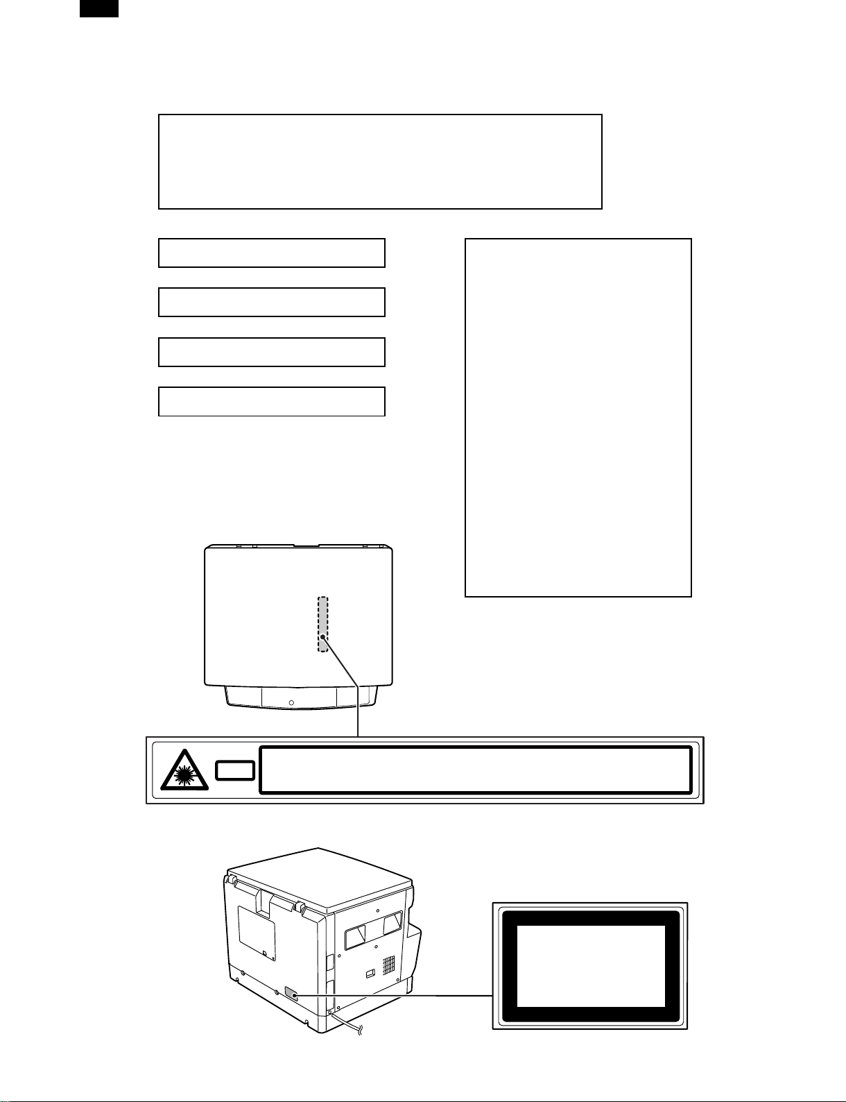
Warning!
This product is a class A product.
If it is operated in households, offices or similar surroundings, it
can produce radio interferences at other appliances, so that the
user has to take adequate countermeasures.
CLASS 1 LASER PRODUCT
LASER KLASSE 1
LUOKAN 1 LASERLAITE
KLASS 1 LASERAPPARAT
VAROITUS!
LAITTEEN KÄYTTÄMINEN
MUULLA KUIN TÄSSÄ
KÄYTTÖOHJEESSA MAINITULLA
TAVALLA SAATTAA ALTISTAA
KÄYTTÄJÄN
TURVALLISUUSLUOKAN 1
YLITTÄVÄLLE
NÄKYMÄTTÖMÄLLE
LASERSÄTEILYLLE.
VARNING
OM APPARATEN ANVÄNDS PÅ
ANNAT SÄTT ÄN I DENNA
BRUKSANVISNING
SPECIFICERATS, KAN
ANVÄNDAREN UTSÄTTAS FÖR
OSYNLIG LASERSTRÅLNING,
SOM ÖVERSKRIDER GRÄNSEN
FÖR LASERKLASS 1.
INVISIBLE LASER RADIATION WHEN OPEN AND INTERLOCKS DEFEATED.
CAUTION
AVOID EXPOSURE TO BEAM.
UNSICHTBARE LASERSTRAHLUNG WENN ABDECKUNG GEÖFFNET UND
VORSICHT
Laserstrahl
SICHERHEITSVERRIEGELUNG ÜBERERÜCKT. NICHT DEM STRAHL AUSSETZEN.
USYNLIG LASERSTRÅLING VED ÅBNING, NÅR SIKKERHEDSAFBRYDERE ER
ADVARSEL
UDE AF FUNKTION. UNDGA UDSAETTELSE FOR STRÅLING.
Disconnect the AC cord before servicing the unit.
USYNLIG LASERSTRÅLING NÅR DEKSEL ÅPNES OG SIKKERHEDSLÅS BRYTES.
ADVERSEL
VARNING
VARO!
UNNGÅ EKSPONERING FOR STRÅLEN.
OSYNLIG LASERSTRÅLNING NÄR DENNA DEL ÄR ÖPPNAD OCH SPÄRRAR ÄR
URKOPPLADE. STRÅLEN ÄR FARLIG. BETRAKTA EJ STRÅLEN.
AVATTAESSA JA SUOJALUKITUS OHITETTAESSA OLET ALTTIINA NÄKYMÄTÖNTÄ
LASERSÄTEILYLLE. ÄLÄ KATSO SÄTEESEEN.
CLASS 1
LASER PRODUCT
LASER KLASSE 1
Page 3

CONTENTS
DM-2000
[1] GENERAL ⋅ ⋅ ⋅ ⋅ ⋅ ⋅ ⋅ ⋅ ⋅ ⋅ ⋅ ⋅ ⋅ ⋅ ⋅ ⋅ ⋅ ⋅ ⋅ ⋅ ⋅ ⋅ ⋅ ⋅ ⋅ ⋅ ⋅ ⋅ ⋅ ⋅ ⋅ ⋅ 1 – 1
1. System configuration ⋅ ⋅ ⋅ ⋅ ⋅ ⋅ ⋅ ⋅ ⋅ ⋅ ⋅ ⋅ ⋅ ⋅ ⋅ ⋅ ⋅ ⋅ ⋅ ⋅ ⋅ ⋅ ⋅ ⋅ ⋅ 1 – 1
2. Note for servicing ⋅ ⋅ ⋅ ⋅ ⋅ ⋅ ⋅ ⋅ ⋅ ⋅ ⋅ ⋅ ⋅ ⋅ ⋅ ⋅ ⋅ ⋅ ⋅ ⋅ ⋅ ⋅ ⋅ ⋅ ⋅ ⋅ ⋅ 1 – 1
[2] SPECIFICATIONS ⋅ ⋅ ⋅ ⋅ ⋅ ⋅ ⋅ ⋅ ⋅ ⋅ ⋅ ⋅ ⋅ ⋅ ⋅ ⋅ ⋅ ⋅ ⋅ ⋅ ⋅ ⋅ ⋅ ⋅ ⋅ 2 – 1
1. Copy mode ⋅ ⋅ ⋅ ⋅ ⋅ ⋅ ⋅ ⋅ ⋅ ⋅ ⋅ ⋅ ⋅ ⋅ ⋅ ⋅ ⋅ ⋅ ⋅ ⋅ ⋅ ⋅ ⋅ ⋅ ⋅ ⋅ ⋅ ⋅ ⋅ ⋅ ⋅ ⋅ ⋅ 2 – 1
2. Specifications of printer section ⋅ ⋅ ⋅ ⋅ ⋅ ⋅ ⋅ ⋅ ⋅ ⋅ ⋅ ⋅ ⋅ ⋅ ⋅ 2 – 3
[3] CONSUMABLE PARTS ⋅ ⋅ ⋅ ⋅ ⋅ ⋅ ⋅ ⋅ ⋅ ⋅ ⋅ ⋅ ⋅ ⋅ ⋅ ⋅ ⋅ ⋅ ⋅ ⋅ 3 – 1
1. Supply system table ⋅ ⋅ ⋅ ⋅ ⋅ ⋅ ⋅ ⋅ ⋅ ⋅ ⋅ ⋅ ⋅ ⋅ ⋅ ⋅ ⋅ ⋅ ⋅ ⋅ ⋅ ⋅ ⋅ ⋅ ⋅ 3 – 1
2. Environment conditions ⋅ ⋅ ⋅ ⋅ ⋅ ⋅ ⋅ ⋅ ⋅ ⋅ ⋅ ⋅ ⋅ ⋅ ⋅ ⋅ ⋅ ⋅ ⋅ ⋅ ⋅ ⋅ 3 – 1
3. Production number identification ⋅ ⋅ ⋅ ⋅ ⋅ ⋅ ⋅ ⋅ ⋅ ⋅ ⋅ ⋅ ⋅ ⋅ 3 – 2
[4] EXTERNAL VIEWS AND INTERNAL
STRUCTURES ⋅ ⋅ ⋅ ⋅ ⋅ ⋅ ⋅ ⋅ ⋅ ⋅ ⋅ ⋅ ⋅ ⋅ ⋅ ⋅ ⋅ ⋅ ⋅ ⋅ ⋅ ⋅ ⋅ ⋅ ⋅ ⋅ ⋅ ⋅ 4 – 1
1. Appearance ⋅ ⋅ ⋅ ⋅ ⋅ ⋅ ⋅ ⋅ ⋅ ⋅ ⋅ ⋅ ⋅ ⋅ ⋅ ⋅ ⋅ ⋅ ⋅ ⋅ ⋅ ⋅ ⋅ ⋅ ⋅ ⋅ ⋅ ⋅ ⋅ ⋅ ⋅ ⋅ ⋅ 4 – 1
2. Internal ⋅ ⋅ ⋅ ⋅ ⋅ ⋅ ⋅ ⋅ ⋅ ⋅ ⋅ ⋅ ⋅ ⋅ ⋅ ⋅ ⋅ ⋅ ⋅ ⋅ ⋅ ⋅ ⋅ ⋅ ⋅ ⋅ ⋅ ⋅ ⋅ ⋅ ⋅ ⋅ ⋅ ⋅ ⋅ ⋅ ⋅ 4 – 1
3. Operation Section ⋅ ⋅ ⋅ ⋅ ⋅ ⋅ ⋅ ⋅ ⋅ ⋅ ⋅ ⋅ ⋅ ⋅ ⋅ ⋅ ⋅ ⋅ ⋅ ⋅ ⋅ ⋅ ⋅ ⋅ ⋅ ⋅ ⋅ 4 – 2
4. Motor, solenoid, clutch ⋅ ⋅ ⋅ ⋅ ⋅ ⋅ ⋅ ⋅ ⋅ ⋅ ⋅ ⋅ ⋅ ⋅ ⋅ ⋅ ⋅ ⋅ ⋅ ⋅ ⋅ ⋅ ⋅ 4 – 3
5. Sensor, switch ⋅ ⋅ ⋅ ⋅ ⋅ ⋅ ⋅ ⋅ ⋅ ⋅ ⋅ ⋅ ⋅ ⋅ ⋅ ⋅ ⋅ ⋅ ⋅ ⋅ ⋅ ⋅ ⋅ ⋅ ⋅ ⋅ ⋅ ⋅ ⋅ ⋅ 4 – 4
6. PWB unit ⋅ ⋅ ⋅ ⋅ ⋅ ⋅ ⋅ ⋅ ⋅ ⋅ ⋅ ⋅ ⋅ ⋅ ⋅ ⋅ ⋅ ⋅ ⋅ ⋅ ⋅ ⋅ ⋅ ⋅ ⋅ ⋅ ⋅ ⋅ ⋅ ⋅ ⋅ ⋅ ⋅ ⋅ ⋅ 4 – 5
7. Cross sectional view ⋅ ⋅ ⋅ ⋅ ⋅ ⋅ ⋅ ⋅ ⋅ ⋅ ⋅ ⋅ ⋅ ⋅ ⋅ ⋅ ⋅ ⋅ ⋅ ⋅ ⋅ ⋅ ⋅ ⋅ ⋅ 4 – 6
[5] UNPACKING AND INSTALLATION ⋅ ⋅ ⋅ ⋅ ⋅ ⋅ ⋅ ⋅ ⋅ 5 – 1
1. Installing conditions ⋅ ⋅ ⋅ ⋅ ⋅ ⋅ ⋅ ⋅ ⋅ ⋅ ⋅ ⋅ ⋅ ⋅ ⋅ ⋅ ⋅ ⋅ ⋅ ⋅ ⋅ ⋅ ⋅ ⋅ ⋅ ⋅ 5 – 1
2. Removal of protective material and
fixing screw ⋅ ⋅ ⋅ ⋅ ⋅ ⋅ ⋅ ⋅ ⋅ ⋅ ⋅ ⋅ ⋅ ⋅ ⋅ ⋅ ⋅ ⋅ ⋅ ⋅ ⋅ ⋅ ⋅ ⋅ ⋅ ⋅ ⋅ ⋅ ⋅ ⋅ ⋅ ⋅ ⋅ 5 – 1
3. Installing of developing cartridge ⋅ ⋅ ⋅ ⋅ ⋅ ⋅ ⋅ ⋅ ⋅ ⋅ ⋅ ⋅ ⋅ ⋅ 5 – 1
4. Removal and storage of fixing screw ⋅ ⋅ ⋅ ⋅ ⋅ ⋅ ⋅ ⋅ ⋅ ⋅ 5 – 2
5. Changing the copy paper size in the tray ⋅ ⋅ ⋅ ⋅ ⋅ ⋅ 5 – 2
6. Installing the printer driver ⋅ ⋅ ⋅ ⋅ ⋅ ⋅ ⋅ ⋅ ⋅ ⋅ ⋅ ⋅ ⋅ ⋅ ⋅ ⋅ ⋅ ⋅ ⋅ ⋅ 5 – 3
7. Expansion memory installation ⋅ ⋅ ⋅ ⋅ ⋅ ⋅ ⋅ ⋅ ⋅ ⋅ ⋅ ⋅ ⋅ ⋅ ⋅ ⋅ 5 – 7
8. Print server card installation ⋅ ⋅ ⋅ ⋅ ⋅ ⋅ ⋅ ⋅ ⋅ ⋅ ⋅ ⋅ ⋅ ⋅ ⋅ ⋅ ⋅ ⋅ 5 – 7
[10] USER SETUP ⋅ ⋅ ⋅ ⋅ ⋅ ⋅ ⋅ ⋅ ⋅ ⋅ ⋅ ⋅ ⋅ ⋅ ⋅ ⋅ ⋅ ⋅ ⋅ ⋅ ⋅ ⋅ ⋅ ⋅ ⋅ ⋅ ⋅10 – 1
1. List of user programs ⋅ ⋅ ⋅ ⋅ ⋅ ⋅ ⋅ ⋅ ⋅ ⋅ ⋅ ⋅ ⋅ ⋅ ⋅ ⋅ ⋅ ⋅ ⋅ ⋅ ⋅ ⋅ ⋅ 10 – 1
2. Setting the user programs ⋅ ⋅ ⋅ ⋅ ⋅ ⋅ ⋅ ⋅ ⋅ ⋅ ⋅ ⋅ ⋅ ⋅ ⋅ ⋅ ⋅ ⋅ 10 – 1
3. Configuration setting ⋅ ⋅ ⋅ ⋅ ⋅ ⋅ ⋅ ⋅ ⋅ ⋅ ⋅ ⋅ ⋅ ⋅ ⋅ ⋅ ⋅ ⋅ ⋅ ⋅ ⋅ ⋅ ⋅ ⋅ 10 – 4
4. Configuration report and test page ⋅ ⋅ ⋅ ⋅ ⋅ ⋅ ⋅ ⋅ ⋅ ⋅ ⋅ 10 – 6
[11] DISASSEMBLY AND ASSEMBLY ⋅ ⋅ ⋅ ⋅ ⋅ ⋅ ⋅ ⋅ 11 – 1
1. High voltage section ⋅ ⋅ ⋅ ⋅ ⋅ ⋅ ⋅ ⋅ ⋅ ⋅ ⋅ ⋅ ⋅ ⋅ ⋅ ⋅ ⋅ ⋅ ⋅ ⋅ ⋅ ⋅ ⋅ ⋅ 11 – 1
2. Optical section ⋅ ⋅ ⋅ ⋅ ⋅ ⋅ ⋅ ⋅ ⋅ ⋅ ⋅ ⋅ ⋅ ⋅ ⋅ ⋅ ⋅ ⋅ ⋅ ⋅ ⋅ ⋅ ⋅ ⋅ ⋅ ⋅ ⋅ ⋅ ⋅ 11 – 1
3. Fusing section ⋅ ⋅ ⋅ ⋅ ⋅ ⋅ ⋅ ⋅ ⋅ ⋅ ⋅ ⋅ ⋅ ⋅ ⋅ ⋅ ⋅ ⋅ ⋅ ⋅ ⋅ ⋅ ⋅ ⋅ ⋅ ⋅ ⋅ ⋅ ⋅ 11 – 2
4. Paper exit section ⋅ ⋅ ⋅ ⋅ ⋅ ⋅ ⋅ ⋅ ⋅ ⋅ ⋅ ⋅ ⋅ ⋅ ⋅ ⋅ ⋅ ⋅ ⋅ ⋅ ⋅ ⋅ ⋅ ⋅ ⋅ ⋅ 11 – 5
5. MCU/Mother board/Printer control PWB ⋅ ⋅ ⋅ ⋅ ⋅ ⋅ 11 – 6
6. Optical frame unit ⋅ ⋅ ⋅ ⋅ ⋅ ⋅ ⋅ ⋅ ⋅ ⋅ ⋅ ⋅ ⋅ ⋅ ⋅ ⋅ ⋅ ⋅ ⋅ ⋅ ⋅ ⋅ ⋅ ⋅ ⋅ ⋅ 11 – 7
7. LSU ⋅ ⋅ ⋅ ⋅ ⋅ ⋅ ⋅ ⋅ ⋅ ⋅ ⋅ ⋅ ⋅ ⋅ ⋅ ⋅ ⋅ ⋅ ⋅ ⋅ ⋅ ⋅ ⋅ ⋅ ⋅ ⋅ ⋅ ⋅ ⋅ ⋅ ⋅ ⋅ ⋅ ⋅ ⋅ ⋅ ⋅ ⋅ ⋅ 11 – 8
8. Tray paper feed section/Paper transport
section ⋅ ⋅ ⋅ ⋅ ⋅ ⋅ ⋅ ⋅ ⋅ ⋅ ⋅ ⋅ ⋅ ⋅ ⋅ ⋅ ⋅ ⋅ ⋅ ⋅ ⋅ ⋅ ⋅ ⋅ ⋅ ⋅ ⋅ ⋅ ⋅ ⋅ ⋅ ⋅ ⋅ ⋅ ⋅ ⋅ 11 – 8
9. Second Tray section ⋅ ⋅ ⋅ ⋅ ⋅ ⋅ ⋅ ⋅ ⋅ ⋅ ⋅ ⋅ ⋅ ⋅ ⋅ ⋅ ⋅ ⋅ ⋅ ⋅ ⋅ ⋅ ⋅ 11 – 10
10. Manual multi paper feed section ⋅ ⋅ ⋅ ⋅ ⋅ ⋅ ⋅ ⋅ ⋅ ⋅ ⋅ ⋅ 11 – 11
11. Power section ⋅ ⋅ ⋅ ⋅ ⋅ ⋅ ⋅ ⋅ ⋅ ⋅ ⋅ ⋅ ⋅ ⋅ ⋅ ⋅ ⋅ ⋅ ⋅ ⋅ ⋅ ⋅ ⋅ ⋅ ⋅ ⋅ ⋅ ⋅ ⋅ 11 – 13
[12] ELECTRICAL SECTION ⋅ ⋅ ⋅ ⋅ ⋅ ⋅ ⋅ ⋅ ⋅ ⋅ ⋅ ⋅ ⋅ ⋅ ⋅ ⋅ ⋅12 – 1
1. Block diagram ⋅ ⋅ ⋅ ⋅ ⋅ ⋅ ⋅ ⋅ ⋅ ⋅ ⋅ ⋅ ⋅ ⋅ ⋅ ⋅ ⋅ ⋅ ⋅ ⋅ ⋅ ⋅ ⋅ ⋅ ⋅ ⋅ ⋅ ⋅ ⋅ 12 – 1
2. Actual wiring diagram ⋅ ⋅ ⋅ ⋅ ⋅ ⋅ ⋅ ⋅ ⋅ ⋅ ⋅ ⋅ ⋅ ⋅ ⋅ ⋅ ⋅ ⋅ ⋅ ⋅ ⋅ ⋅ ⋅ 12 – 2
[6] ADJUSTMENTS ⋅ ⋅ ⋅ ⋅ ⋅ ⋅ ⋅ ⋅ ⋅ ⋅ ⋅ ⋅ ⋅ ⋅ ⋅ ⋅ ⋅ ⋅ ⋅ ⋅ ⋅ ⋅ ⋅ ⋅ ⋅ ⋅ ⋅ 6 – 1
1. Adjustment item list ⋅ ⋅ ⋅ ⋅ ⋅ ⋅ ⋅ ⋅ ⋅ ⋅ ⋅ ⋅ ⋅ ⋅ ⋅ ⋅ ⋅ ⋅ ⋅ ⋅ ⋅ ⋅ ⋅ ⋅ ⋅ ⋅ 6 – 1
2. Copier adjustment ⋅ ⋅ ⋅ ⋅ ⋅ ⋅ ⋅ ⋅ ⋅ ⋅ ⋅ ⋅ ⋅ ⋅ ⋅ ⋅ ⋅ ⋅ ⋅ ⋅ ⋅ ⋅ ⋅ ⋅ ⋅ ⋅ ⋅ 6 – 1
[7] SIMULATIONS ⋅ ⋅ ⋅ ⋅ ⋅ ⋅ ⋅ ⋅ ⋅ ⋅ ⋅ ⋅ ⋅ ⋅ ⋅ ⋅ ⋅ ⋅ ⋅ ⋅ ⋅ ⋅ ⋅ ⋅ ⋅ ⋅ ⋅ ⋅ 7 – 1
1. Entering the simulation mode ⋅ ⋅ ⋅ ⋅ ⋅ ⋅ ⋅ ⋅ ⋅ ⋅ ⋅ ⋅ ⋅ ⋅ ⋅ ⋅ ⋅ 7 – 1
2. Cancelling the simulation mode ⋅ ⋅ ⋅ ⋅ ⋅ ⋅ ⋅ ⋅ ⋅ ⋅ ⋅ ⋅ ⋅ ⋅ ⋅ 7 – 1
3. List of simulations ⋅ ⋅ ⋅ ⋅ ⋅ ⋅ ⋅ ⋅ ⋅ ⋅ ⋅ ⋅ ⋅ ⋅ ⋅ ⋅ ⋅ ⋅ ⋅ ⋅ ⋅ ⋅ ⋅ ⋅ ⋅ ⋅ ⋅ 7 – 1
4. Contents of simulations ⋅ ⋅ ⋅ ⋅ ⋅ ⋅ ⋅ ⋅ ⋅ ⋅ ⋅ ⋅ ⋅ ⋅ ⋅ ⋅ ⋅ ⋅ ⋅ ⋅ ⋅ ⋅ 7 – 2
[8] FLASH ROM VERSION UP PROCEDURE ⋅ ⋅ 8 – 1
1. MCU/E SORT ⋅ ⋅ ⋅ ⋅ ⋅ ⋅ ⋅ ⋅ ⋅ ⋅ ⋅ ⋅ ⋅ ⋅ ⋅ ⋅ ⋅ ⋅ ⋅ ⋅ ⋅ ⋅ ⋅ ⋅ ⋅ ⋅ ⋅ ⋅ ⋅ ⋅ ⋅ 8 – 1
2. Printer control PWB firmware version up ⋅ ⋅ ⋅ ⋅ ⋅ ⋅ 8 – 2
[9] TROUBLE CODE LIST ⋅ ⋅ ⋅ ⋅ ⋅ ⋅ ⋅ ⋅ ⋅ ⋅ ⋅ ⋅ ⋅ ⋅ ⋅ ⋅ ⋅ ⋅ ⋅ ⋅ 9 – 1
1. Trouble code list ⋅ ⋅ ⋅ ⋅ ⋅ ⋅ ⋅ ⋅ ⋅ ⋅ ⋅ ⋅ ⋅ ⋅ ⋅ ⋅ ⋅ ⋅ ⋅ ⋅ ⋅ ⋅ ⋅ ⋅ ⋅ ⋅ ⋅ ⋅ 9 – 1
2. Details of trouble codes ⋅ ⋅ ⋅ ⋅ ⋅ ⋅ ⋅ ⋅ ⋅ ⋅ ⋅ ⋅ ⋅ ⋅ ⋅ ⋅ ⋅ ⋅ ⋅ ⋅ ⋅ ⋅ 9 – 2
Page 4
DM-2000
[1] GENERAL
1. System configuration
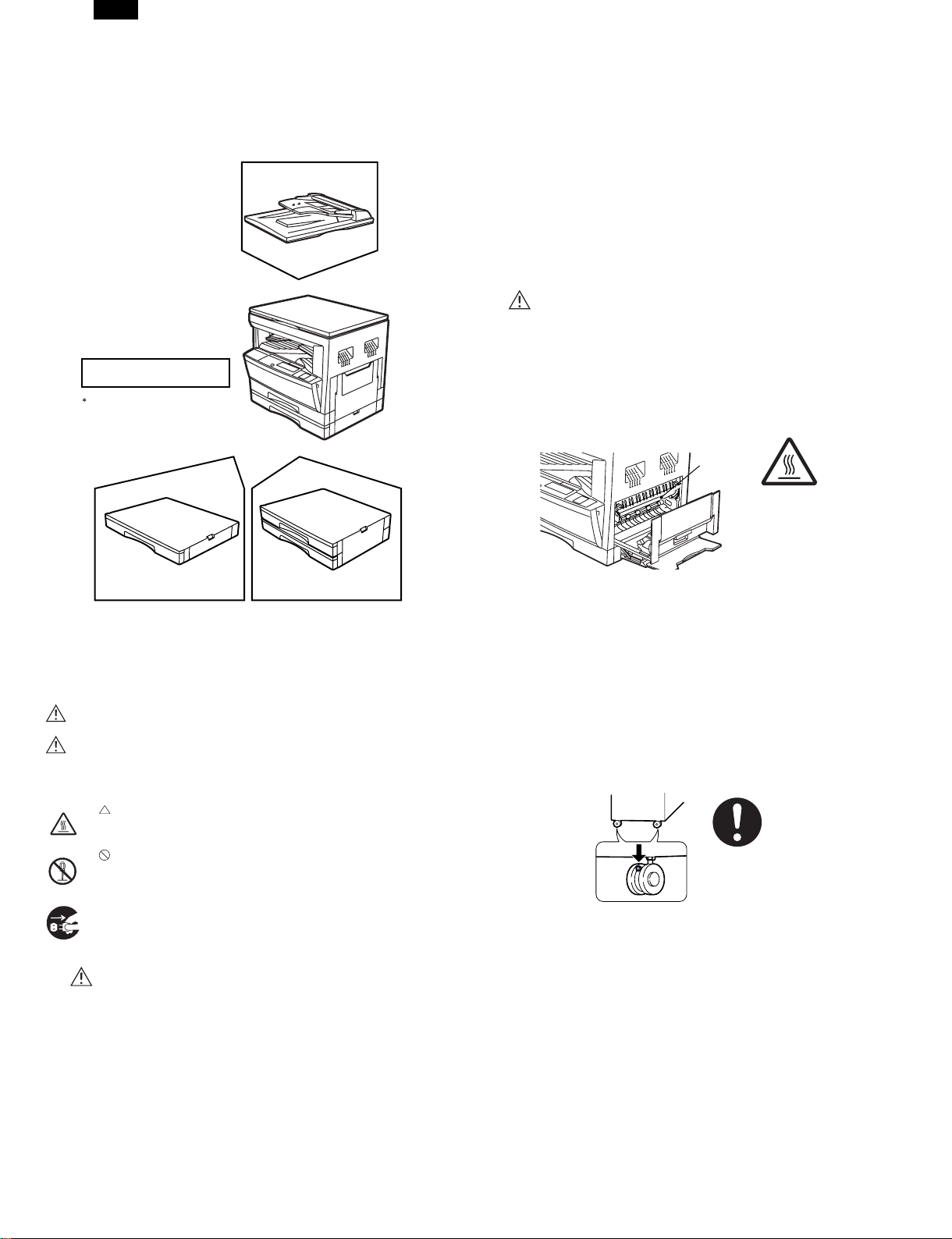
A number of options are available for the DM System which allow you
to configure the system to meet your particular needs. The options include the following.
Single pass feeder
(DM-SP1)
Electronic sorting kit (DM-EB1)
Facsimile expansion kit (DM-FX1)*
This option is not used for the copier
operation.
For description of this option, see its
separate manual.
cause an electric shock when touched. Do not leave the machine
with the cabinet removed. It is very dangerous for the user to
touch the inside of the machine.
5) Do not damage, brake, or work the power cord. Do not put a
heavy thing on the power cord. Do not pull or bend the power cord
extremely. Otherwise, the power cord may be damaged to cause
a fire or an electric shock.
6) Do not put a vessel with water in it on the machine. Do not put a
metal piece on the machine, which may drop into the machine,
causing a fire or an electric shock.
7) If water or a metal piece drops into the machine, turn off the power
switch, disconnect the power plug, then remove the dropped thing.
8) Do not use a wet hand to disconnect or insert the power plug and
to operate or service the machine. It may cause an electric shock.
B. CAUTION
1) Avoid installation on an unstable surface or a slant surface. Otherwise, it may drop from the surface, resulting in an injury. It is advisable to use the optional paper feed desk or the exclusive-use
desk.
2) Avoid installation in a humid or dusty place. Otherwise, a fire or an
elctric shock may be resulted.
3) The fusing section is very high. Be careful not to burn when servicing.
Fusing section
250-sheet paper feed unit
(DM-DE1)
2x250-sheet paper feed unit
(DM-DE2)
2. Note for servicing
Pictogram
This Service Manual uses some pictographs to assure safe operation.
Please understand the meanings of pictographs before servicing.
WARNING: If this WARNING should be ignored, a serious danger
CAUTION: If this CAUTION should be ignored, an injury or a
Meanings of pictographs
A. WARNING
1) Never use a power source of more than 15A, 100V.
Avoid complex wiring, which may lead to a fire or an electric
shock.
2) When any abnormality occurs, such as smoke or bad smell, do not
use the machine. If used in abnormal conditions, a fire or an
electric shock may be resulted.
3) Be sure to connect the grounding wire. If an electric leakage occurs without grounding, a fire or an electric shock may be resulted.
To protect the machine and the power unit from lightening,
grounding must be made.
4) When removing the cabinet of the machine, use an extreme care.
There is a high voltage section inside the machine which may
to life or a serial injury would be resulted.
damage to properties would be resulted.
This pictograph means that a care must be taken. In the
pictograph, the concrete content is drawn. (High temperature
in this example)
This pictograph means inhibition. The concrete content of
inhibition is shown in or near the pictograph. (Inhibition of disassembly in this example)
●This pictograph means a thing which must be done. (Dis-
connecting the power plug from the power outlet in this example)
4) When disconnecting the power plug from the power outlet, do not
pull the power cord. Otherwise, the cord may be damaged, resulting in exposed core or disconnection, causing a fire or an electric
shock.
5) Do not throw toner or a toner cartridge in a fire. Otherwise, toner
may pop and burn you.
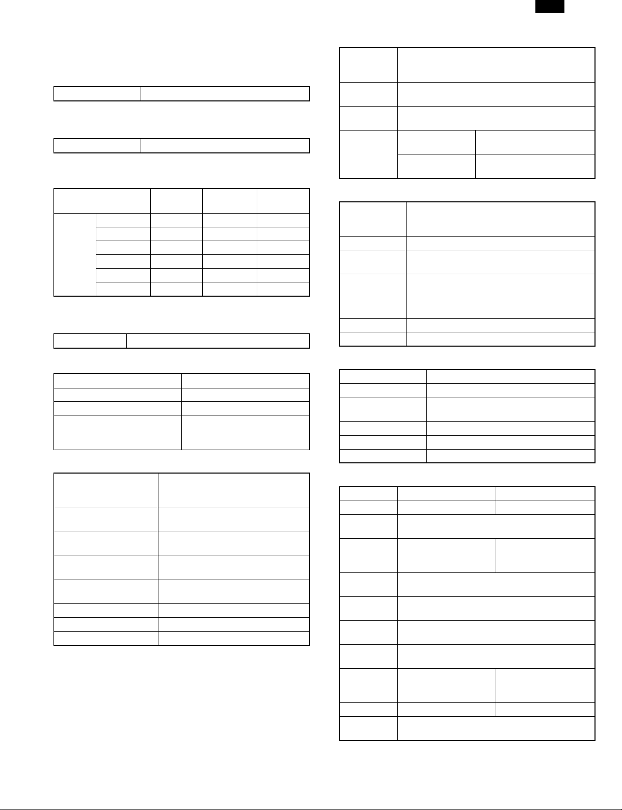
6) When using the optional paper feed desk or the exclusive-use
desk, be sure to fix the adjusters on the floor, and lock the casters.
As shown in the figure, rotate the adjuster in the fixing direction
until it makes contact with the floor. Lock the casters to fix the
machine. (If the casters are not locked, the machine may gradually
move so that the SPF cable may be rubbed with the wall, causing
disconnection.
When moving the machine a little for reforming the office, turn the
adjuster to release lock of the casters. (After moving, lock the adjusters and casters to fix the machine.)
7) Do not see the light source and the laser beams. Otherwise the
eyes may be damaged.
8) When moving the machine, turn off the power switch and the
heater switch, and be sure to disconnect the power plug from the
power outlet. If not, the cord may be damaged to cause a fire or
an electric shock.
9) It is very dangerous to perform reception or printing during servicing. When servicing with the cabinet removed, pull out the
telephone line and the printer cable from the machine. (The laser
print function and the Fax function are options.)
10) There are some sharp edges inside the machine. Be careful not
to injure your fingers when servicing.
1 – 1
Page 5
DM-2000
[2] SPECIFICATIONS
1. Copy mode
A. Type
Type Desk-top
B. Copy speed
(1) Basic speed
1 scan multi copy 20 sheets/min
Condition: Copy speed in the normal copy.
(2) Continuous copy speed (Sheets/min)
Paper size Normal
11" × 17" 10 10 10
8.5" × 14" 12 12 12
Inch
system
8.5" × 13" 12 12 12
8.5" × 11" 20 20 20
8.5" × 11"R 15 15 15
8.5" × 5.5" 20 20 20
C. First copy time
(1) Basic speed
First copy time 7.2 sec (8.5" × 11"/1st cassette/with OC)
Enlargement
(200%)
Reduction
(50%)
E. Paper feed
Max.: A3, 11" × 17"
Copy size
Paper feed
system
Paper feed
capacity
Remaining
quantity
detection
(1) Paper feed section of the copier
Paper feed
size
Side front Front 2 step
Paper feed
capacity
Detection
Weight 56 ∼ 80 g/m2 15 ∼ 21 lbs
Special paper Recycled paper
Min.: A6, 5.5" × 8.5" (For B6/A6 and 5.5" × 8.5",
Multi bypass tray only.)
2 cassette + Multi bypass tray
250 × 2 (Paper feed tray) + 100 (Multi bypass
tray)(56 ∼ 80 g/m2 equivalent)
Cassette section
Multi bypass tray
11" × 17", 8.5" × 14", 8.5" × 13", 8.5" × 11",
8.5" × 11"R, 8.5" × 5.5" (8.5" × 5.5" is only for
tray 1)
250 sheets (56 ∼ 80 g/m2 15 ∼ 21 lbs
equivalent)
Paper empty detection available, size detection
(by key input)
Detection size: 11" × 17", 8.5" × 14",
8.5" × 11", 8.5" × 11"R, 8.5" × 5.5"
Empty detection available,
size detection by key input
Only empty detection
available
D. Document
Max. document size 11" × 17"
Document reference position Left side center
Detection (Platen) Available
11" × 17", 8.5" × 14",
Detection size
(1) SPF/R-SPF
Standard/Option
Document load capacity
Document size
(Max. ∼ Min.)
Document replacement
speed
Document set/Paper
feed direction
Document weight 56 ∼ 90 g/m2, 15 ∼ 23.9 lbs
Document size detection On the document feed tray
Document mixture Copy mode: Not Available
8.5" × 11", 8.5" × 11"R,
8.5" × 5.5"
Option
SPF; DM-SP1
RSPF; Not available
30 sheets (56 ∼ 90 g/m2 15 ∼ 23.9
lbs equivalent)
11" × 17" ∼ 8.5" × 5.5"
16 sheets/min (8.5" × 11" normal
copy)
Face up, Center reference, Paper
feed from the top
(2) Manual paper feed section
Paper feed size 11" × 17" ∼ 5.5" × 8.5"
Paper feed capacity 100 sheets
Detection
Weight 56 ∼ 128 g/m2 15 ∼ 34 lbs
Special paper Recycled paper, OHP film, labels
Paper feed Single except for recycled paper
(3) Option paper feed unit
Model DM-DE1 DM-DE2
Paper feed
size
Capacity
(56 ∼ 80
g/m2)
Paper
weight
Dehumidifier
heater
Detection
Paper size
setting
External
dimensions
(W × D × H)
Weight About 5 kg About 10 kg
Special
paper
Size detection not available, paper empty
detection available
1-step paper feed unit 2-step paper feed unit
11" × 17", 8.5" × 14", 8.5" × 11",
8.5" × 11"R
About 250 sheets
× 1 step
56 ∼ 80 g/m2 15 ∼ 21 lbs
Paper empty detection, size detection
(by key input)
User setting (by key input)
590 × 571 × 88 mm 590 × 571 × 173.5 mm
Recycled paper
About 250 sheets
× 2 steps
None
2 – 1
Page 6
DM-2000
F. Job speed
S-S (1st step) 80% (document replacement rate)
Condition: With SPF
G. Multi copy
Max. number of multi copy 99 sheets
H. Warmup time
Warmup time
Pre-heat Available
Approx. 35 sec
(Condition: Standard condition)
I. Copy magnification ratio
Fixed magnification ratio
Zooming 50 ∼ 200%
Independent
zooming/vertical
Independent zooming
(horizontal)
50, 64, 77, 95, 100, 121, 129, 141,
200%
Available (50 ∼ 200%)
Available (50 ∼ 200%)
J. Print density
Density mode Auto/Manual/Photo
No. of manual
adjustment
Toner save mode Set by the user program
5 steps (Manual/Photo)
K. Void width
Void area
Image loss
Lead edge 1 ∼ 4 mm, rear edge 4 mm or less,
both side 4 mm or less
Max. 5/32" (4 mm) (leading and trailing edges)
Max. 5/32" (4 mm) (along other edges in total)
L. Auto duplex
Standard/Option Not installable
M. Paper exit/finishing
Paper exit
section capacity
Job separator
Full detection Available (Job separator)
Finishing Electronic sort board: Option (DM-EB1)
Electronic sort
capacity
Offset function Available (by the shifer)
Staple function None
Face down 250 sheets
Job separator, Standard provision
Upper: FAX/Printer, Lower: Copier
Upper: 100 sheets, Lower 150 sheets
8.5" × 11" standard document 60 sheets
(1) Electronic sort board (Option)
60 sheets of A4 (8.5" × 11")
standard documents
60 sheets of A4 (8.5" × 11")
standard documents
Electronic sort
Rotation copy
2 in 1, 4 in 1
Edge erase
Center erase
Margin shift
Sorting
Grouping
If there is paper of same size as the document,
the image is rotated to copy even though the
paper is set in the different direction from the
document direction.
Copies of 2 pages or 4 pages are integrated
into one surface. Divided by solid lines,
(Selectable by the user program.)
Images surrounding the document are erased
when copying. (Adjustable in 0 ∼ 20 mm (5 mm
step)/0" ∼ 1" (1/4" step) by the user program.)
The image at the center is erased when
copying. (Adjustable in 0 ∼ 20 mm (5 mm
step)/0" ∼ 1" (1/4" step) by the user program.)
Binding margin is made at the left edge of the
set documents.
N. Additional functions
APS
AMS
Duplex
Document count
Sorter
Independent zooming Vertical/Horizontal: 50 ∼ 200%
1 set 2 copy
Binding margin Shift width 9 mm/1/4"
Edge erase Adjustable 0 ∼ 20 mm/0" ∼ 1"
Black-white reversion Whole surface only
2 in 1, 4 in 1
Rotation copy
Memory copy Only one page memory installed.
Pre-heat function Conditions set by the user program
Auto power shut off
function
Auto tray switching
Message display (FAX/Printer extension)
User program
Total counter
: When an option is installed
: Available : Not available
(APS not available by flowing in
during use of SPF)
(AMS not available by flowing in
during use of SPF)
When the electronic sort board
installed.
Enlargement inhibited, inhibited
during the use of SPF
Conditions set by the user program
O. machine composition
(1) Option
Machine Model Power supply
250 sheets paper feed unit DM-DE1 Supplied by the copier.
500 sheets paper feed unit DM-DE2 Supplied by the copier.
SPF DM-SP1 Supplied by the copier.
Electronic sorting kit DM-EB1 Supplied by the copier.
Facsimile expansion kit DM-FX1 Supplied by the copier.
2 MB FAX memory AR-MM5
4 MB FAX memory AR-MM6
8 MB FAX memory AR-MM7
2 – 2
Page 7
DM-2000
P. Other specifications
Photoconductor type OPC (Organic Photo Conductor)
Photoconductor drum dia. 30 mm
Copy lamp Xenon lamp
Developing system
Charging system Saw teeth charging
Transfer system (+) DC corotoron
Separation system (–) DC corotoron
Fusing system Heat roller
Cleaning system Contact blade
Dry 2-component magnetic brush
development
Q. Package form
Body
Body/Accessories (NIC board is separately
packed.)
R. External view
External dimensions
(W × D × H)
Occupying area
(W × D)
Weight About 36.5 kg
590 × 531 × 552 mm (including Platen)
590 × 531 mm
(When the multi bypass tray is installed.)
S. Power source
Voltage AC120V ± 15%
Frequency 50/60Hz common
T. Power consumption
Max. power consumption About 1.5 KWh
∗ EnergyStar standard (The second level conformity)
Pre-heat About 60 Wh
Auto power shut off About 4.8 Wh
U. Digital performance
Resolution
Gradation
Reading 400 dpi
Writing 600 dpi
Reading 256 gradations
Writing Binary
2. Specifications of printer section
A. Basic specifications
Item Contents
Print speed 20 PPM
Resolution
Toner save Available
Paper feed tray
Paper size
Paper exit Face down system
Shifter Available
Page
description
language
(standard)
Dot emulation None
Page protection
function
Interface
Interface cable
Interface select Auto
Emulation select Auto
Plug and play Conforming (only with Windows 95/98)
Printer driver
Network control
software
Built-in fonts
600 dpi, 300 dpi (1,200 dpi equivalent by
smoothing)
Multi bypass tray
Tray 1, Tray 2, Tray 3, Tray 4 (Depends on
the machine and the option installation.)
A3, B4, A4R,
B5R, A5, 11" ×
17", 8.5" × 14",
Multi bypass tray
Tray
1 ∼ 4
PCL6 emulation
PCL5e emulation
PostScript Level 2 emulation
Available
Standard
Option
Use IEEE1284 conforming parallel cable.
(shielded and grounded)
Max. length Within 3.0 m
Microsoft Windows 3.1
Microsoft Windows 95
Microsoft Windows 98
Microsoft Windows
NT4.0
Macintosh OS version
7.5 or later
Printer Administration Utility
Outline 45 fonts (PCL6 compatible)
Outline 35 fonts (PS2 compatible)
11" × 17", 8.5" × 14", 8.5" × 11",
8.5" × 11"R, 8.5" × 5.5", 8.5" ×
13"
IEEE1284
port
Expansion
slot
10/100
Base TX
8.5" × 11"R, 8.5"
× 5.5"R, 8.5" ×
13", 8.3" × 13",
7.25" × 10.5"R,
DL, C5, COM10
Compatibility mode
Nibble mode
Expansion slot for
Print Server Card
× 1
TCP/IP, IPX/SPX
PCL6PCL
5e
PS2
2 – 3
Page 8
DM-2000
Item Contents
Outline 31 fonts (PCL6 compatible) for
Screen font
Memory
Conforming PC
Windows
Outline 35 fonts (PS2 compatible) for
Windows
Standard 8 MB
Max. 136 MB
Expansion slot DIMM slot × 2
Expansion memory
(For details, refer to
the descriptions below.)
IBM PC-AT compatible
Apple Macintosh Computer
B. Printer driver specifications
(1) System
OS PCL6
Microsoft Windows 3.1
IBM
PC/AT
Macintosh
(2) Kinds of printer drivers
PCL5e for Windows 3.1/95/98
PCL5e for Windows NT4.0
PCL6 for Windows 95/98
PCL6 for Windows NT4.0
PostScript Level2 for Windows
3.1/95/98
PostScript Level2 for Windows NT4.0
Microsoft Windows 95
Microsoft Windows 98
Microsoft Windows NT4.0
OS 7.5 or lator
Printer driver name Name on PC screen
64 MB, 32 MB,
16 MB
(Commercially
available 168 pin
EDO DIMM 60ns
or faster used)
PCL5e
SHARP DM-2000
Series PCL5e
SHARP DM-2000
Series PCL6
SHARP DM-2000
Series PS2
PS2
Item PCL6 PCL5e
Smoothing On, Off
Resolution Settings 600 dpi, 300 dpi
Graphics Mode HP-GL/2 (Vector), Raster
Half Tone
Font Source Resident Fonts, Download Fonts
True Type Mode
Input Tray
Duplex Capability Yes, No
Installed RAM
Unit 0.01", 0.1 mm
Set
content of
custom
paper
Set
content of
water mark
Width
Length
Position
Size 6 ∼ 900
Angle ±90˚
Text
Edit Fonts Refer to the following Font List.
Edit Density 0 ∼ 255
Transparent
Text
On First
Page Only
As Outline
Only
Photo Images, Line Art, Scanned
Images
Download as True Type, Download
as bitmap font, Print as graphics
Two Trays, Three Trays, Four
Trays
8 MB, 24 MB, 40 MB, 56 MB, 72
MB, 88 MB, 104 MB, 136 MB
1000 to 2969
(In the case of 0.1 mm)
394 to 1169 (In the case of 0.01")
1480 to 4318
(In the case of 0.1 mm)
583 to 1700 (In the case of 0.01")
Depends on the paper size.
MAX Short –5.84" ∼ 5.84"
Long –8.5" ∼ 8.5"
TOP SECRET
CONFIDENTIAL
DRAFT
ORIGINAL
COPY
Yes, No
Yes, No
Yes, No (Only when Transparent
Text is OFF.)
(3) Set content
Item PCL6 PCL5e
Copies 1 to 999
Orientation Portrait, Landscape
Document Style
Paper Source
Paper Size
N-Up Printing 1-Up, 2-Up, 4-Up
Border On, Off
Fit to Page On, Off
Page Protection On, Off
Toner Save Mode On, Off
1-Sided, 2-Sided (Book), 2-Sided
(Tablet)
Auto, Tray 1, Tray 2, Tray 3, Tray
4, Bypass Tray
A3 (297 × 420 mm), B4 (257 ×
364 mm), A4 (210 × 297 mm), A5
(148 × 210 mm), B5 (182 × 257
mm), Ledger (11" × 17"), Letter
(8.5" × 11"), Legal (8.5" × 14"),
Executive (7.25" × 10.5"), Folio
(8.3" × 13"), Invoice (5.5" × 8.5"),
Foolscap (8.5" × 13"), DL, C5,
COM10, Custom Paper
(4) LCD display
a. LCD message
Status LCD display Content
Online Online
Error
2 – 4
Data Loss
Error
Memory
Full
Out of
Paper
AUTO
PCL PCL
PS2 PS2
HEX HEX
Press ENTER
Press ENTER
Tray 1 <Paper Size>
Tray 2 <Paper Size>
Tray 3 <Paper Size>
Tray 4 <Paper Size>
Bypass
<Paper Size>
Tray <Paper Size>
Auto select to
emulation
When the paper
feed tray is
selected to other
than AUTO.
When the paper
feed tray is
selected to AUTO.
Page 9
Status LCD display Content
Toner empty
Error
User
setting
Check
Panel
Clear
Paper Path
Copies
Resolution
Smoothing
Toner Save
Main Menu
Network
Menu
PS2 Menu Print PS2 Error
Interface
Menu
Test
Printing
Menu
Page Protection
2-Sided Printing
Paper Source Tray select
Paper Size Paper size select
Orientation
Emulation Emulation setting
Set IP Address
Set Subnet Mask
Set Default Gateway
Enable TCP/IP
Enable Netware
Enable EtherTalk
Reset to Defaults
I/O Time Out
Configuration Page
PCL Font List
PS2 Font List
Drum replacement
Cover open
Service call error
Paper jam
Paper exit tray full
Printing of the set
quantity is made.
Printing at the set
resolution is made.
Smoothing
function setting.
Toner save mode
setting
Setting of page
protection function
Setting of duplex
function and
binding direction
Setting of print
direction
IP address
setting is made.
Subnet Mask
setting is made.
Default Gateway
setting is made.
Enable/Disable
TCP/IP
Enable/Disable
Netware
Enable/Disable
EtherTalk
Reset Print
Server Card to
default
Setting of printing
in case of PS
Error
If data reception
is not completed
within the set
time, it is judged
as a time out
error.
Configuration
page is printed.
PCL6 Font page
is printed.
PS2 Font page is
printed.
DM-2000
b. LED display
Indicates that the printer is offline and data cannot be
transferred or printed. Make
Extinguished
ON LINE light
Lit
Extinguished
DATA light
c. Operation keys
LINE key
MENU key
ITEM key
Left arrow key
Right arrow key
ENTER key Used to enter a new value.
∗ Invalid when the printer is on-line.
(5) Network board
10/100 Base TX TCP/IP, IPX/SPX, Ether Talk
10 Base T/2 TCP/IP, IPX/SPX, Ether Talk
(6) PC environment
a. In the case of IBM PC/AT or compatible computers
Computer
Type
Operating
System
CPU
RAM
Lit
Blinking
Changes between the on-line and off-line
modes.
When the printer is on-line, it can receive
data from the computer with which it is
connected.
When the printer is off-line, you can use
operation panel keys to make print settings.
Note, however, that you cannot make settings
if the “Data Remaining” message is displayed.
Used to show setting menus on the display in
sequence.∗
Used to show the setting items of the
selected menu in sequence.∗
Used to change the value of any item.∗
IBM PC/AT or compatible computer equipped with a
bi-directional parallel interface and CD-ROM drive
Windows 95, Windows 98, Windows NT4.0
Windows 3.1
Windows 95: 486SX or better
Windows 98: 486DX/66MHz or better (Pentium or
better is recommended.)
Windows NT4.0: 486/25MHz or better
Windows 95: 8 MB or more (12 MB or more is
recommended.)
Windows 98: 16 MB or more (32 MB or more is
recommended.)
Windows NT4.0: 16 MB or more
settings from the operation
panel in this mode. Note,
however, that you cannot make
settings if the “Data Remaining”
message is displayed.
Indicates that the printer is online and data can be transferred
and printed.
Indicates that there is no data
being received or processed.
Indicates that the printer is
receiving or processing print
data.
Indicates that there is print data
remaining in memory that has
not yet been printed.
2 – 5
Page 10
DM-2000
b. In the case of Macintosh
Computer
Type
Operating
System
CPU MC68040 or Power PC micro processor
RAM
Macintosh computer
Macintosh System 7.5 to 8.5
16MB or more for Power PC micro processor
machine
12MB or more for 68040 machine
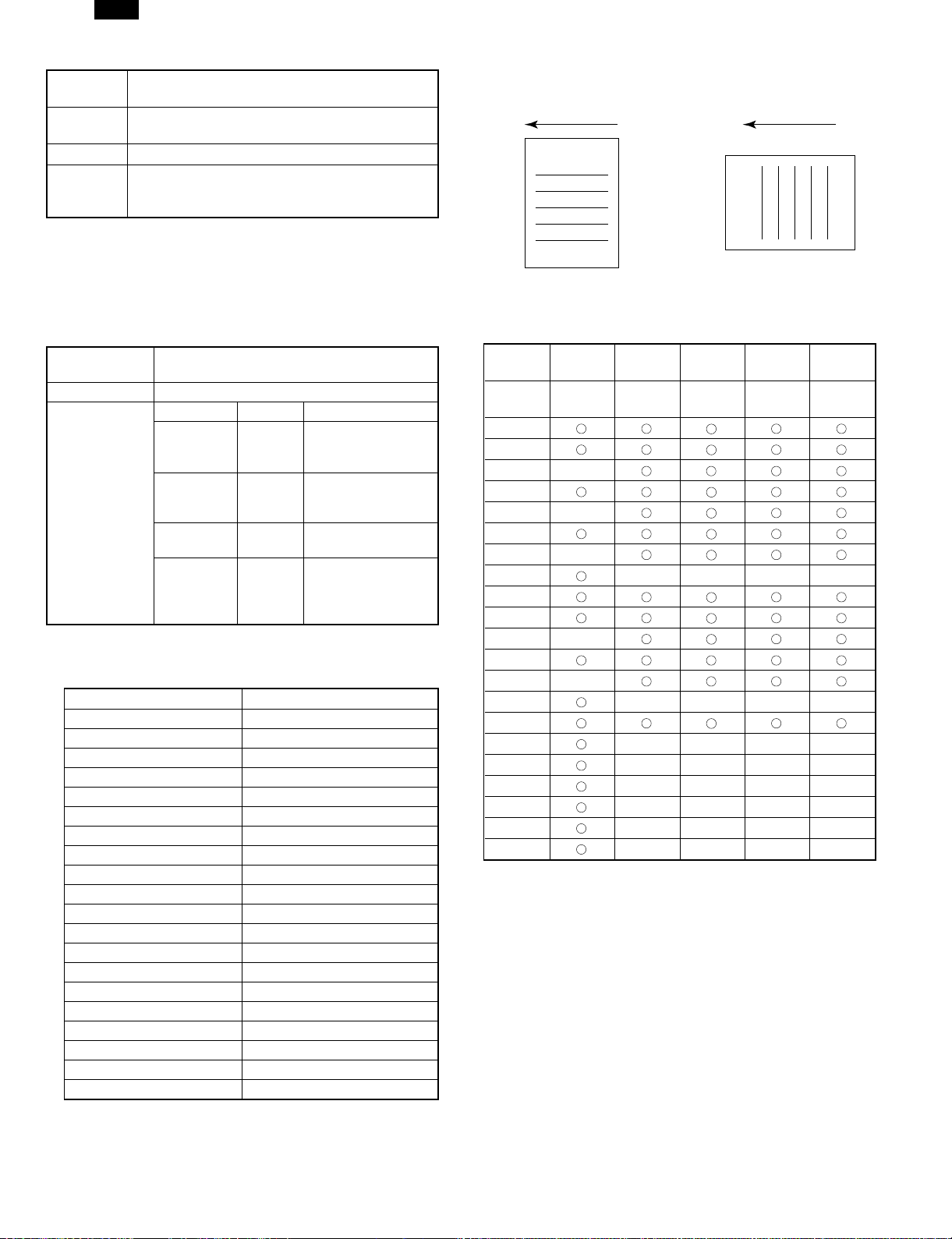
Side set to the
paper feed port
Transport direction
ABC...
= Long side
Side set to the
paper feed port
Transport direction
= Short side
(7) Expansion memory
Memory expansion realizes the following effects.
● Increased processing speed of outline fonts or complex graphic data.
● Shorter release time from a printing job of the computer.
● Allows high resolution printing.
● Complex data can be printed without data loss error or memory full
error.
Type
DIMM (60ns/EDO/168pin) (Use commercially
available one.)
Capacity 64 MB, 32 MB, 16 MB
Vendor Capacity Model name
Recommendable
product
Viking
Components
Kingston
Simple
Technology
Transcend
16 MB
32 MB
64 MB
16 MB
32 MB
64 MB
16 MB
64 MB
16 MB
32 MB
32 MB
64 MB
VE2641U2EN3-60
VE4641U4EN3-60
VE8641U4EN3-60
KTA4400/16
KTM4X64VN42-60EG
KTM8X64VN84-60EG
STI642004UD1-60VG
STI648104UD1-60VG
TS2MLE64V6PN
TS4MLE64V6TN
TS4MLE64V6UN
TS8MLE64V6VN
(8) Paper handling specifications
a. Paper feed direction
<1> Paper size and image transport direction
Paper Size Side set to the paper feed port
A3 Short side
B4 Short side
A4 Long side
A4R Short side
B5 Long side
B5R Short side
A5 Long side
A5R Short side
Ledger Short side
Legal Short side
Letter Long side
LetterR Short side
Invoice Long side
InvoiceR Short side
Foolscap Short side
Folio Short side
Executive Short side
COM-10 Short side
C5 Short side
DL Short side
ABC...
For paper feed of the multi bypass tray, the short side must be set
to the paper fed port regardless of paper size for making print data.
b. Paper feed port
Tray kind
Capacity
Bypass
Tray
100
sheets
Tray 1 Tray 2 Tray 3 Tray 4
250
sheets
250
sheets
250
sheets
250
sheets
A3
B4
A4
A4R
B5
B5R
A5
A5R
Ledger
Legal
Letter
LetterR
Invoice
InvoiceR
Foolscap
Folio
Executive
COM-10
C5
DL
Custom
∗ The number of trays supported depends on each model.
∗ When printing with the multi bypass tray, the printer board cannot
recognize the set paper direction, and therefore it regards that the
short side of paper would be set (vertical transport direction) to make
data.
c. Tray selection
Paper handling is controlled on the copier side. The printer board
sends the Video I/F command to the digital copier according to the
computer direction of the tray.
2 – 6
Page 11
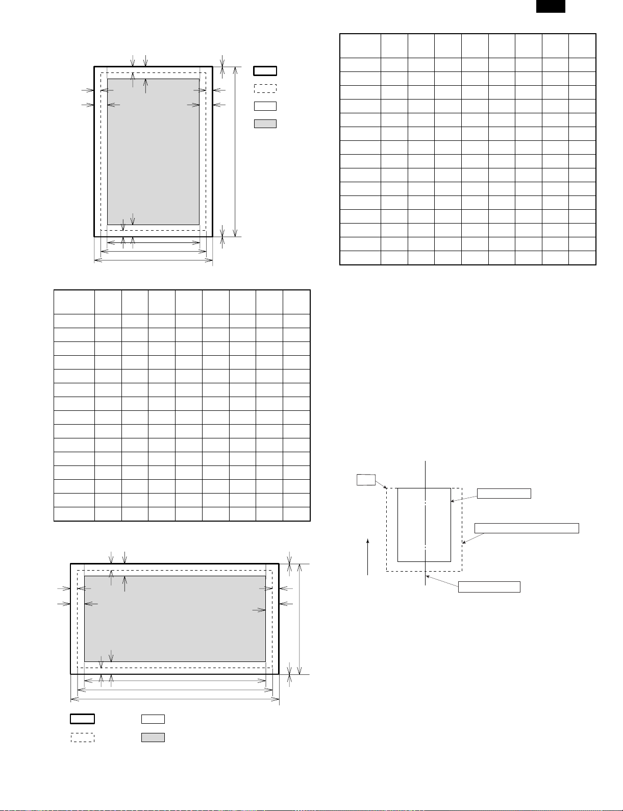
(9) Print Area
H
Physical
Page
EE
D
F
E
Paper
size
ABCDEFGH
F
C
G
A
E
D
B
H
Printable
Area
Logical
Page
HP/GL
Picture
Frame
A3 7014 9920 6730 142 100 300 6814 0
B4 6070 8597 5786 142 100 300 5870 0
A4 4960 7014 4676 142 100 300 4760 0
B5 4298 6070 5770 142 100 300 4098 0
A5 3508 4960 3224 142 100 300 3308 0
Ledger 6600 10200 6300 150 100 300 6400 0
Legal 5100 8400 4800 150 100 300 4900 0
Letter 5100 6600 4800 150 100 300 4900 0
Invoice 3300 5100 3000 150 100 300 3100 0
Foolscap 5100 7800 4800 150 100 300 4900 0
Folio 4980 7800 4680 150 100 300 4780 0
Executive 4350 6300 4050 150 100 300 4150 0
COM-10 2474 5700 2174 150 100 300 2274 0
C5 3826 5408 3542 142 100 300 3626 0
DL 2598 5196 2314 142 100 300 2398 0
(Unit: Dots/600DPI)
DM-2000
PAPER
SIZE
A3 9920 7014 9684 118 100 300 9720 0
B4 8597 6070 8361 118 100 300 8397 0
A4 7014 4960 6778 118 100 300 6814 0
B5 6070 4298 5830 118 100 300 5870 0
A5 4960 3508 4720 118 100 300 4760 0
Ledger 8400 5100 8160 120 100 300 8200 0
Legal 8400 5100 8160 120 100 300 8200 0
Letter 6600 5100 6360 120 100 300 6400 0
Invoice 5100 3300 2860 120 100 300 4900 0
Foolscap 7800 5100 7560 120 100 300 7600 0
Folio 7800 4980 7560 120 100 300 7600 0
Executive 6300 4350 6060 120 100 300 6100 0
COM-10 5700 2474 3460 120 100 300 5500 0
C5 5408 3826 5172 118 100 300 5208 0
DL 5196 2598 4960 118 100 300 4996 0
∗ Top Margin
The set value is received from the digital copier and data are made according to the set value.
∗ Left margin
Since the paper size sensor is not set, the digital copier does not know
the size and direction of paper inserted. Therefore, the left margin is
set according to the paper size indicated by the print data sent from the
computer, and printing is made. If the computer does not specify the
paper size or in the case of custom size, the left margin is set according to the default paper size.
(10) Print reference
This machine employs the center reference system.
Since the digital copier is not equipped with the paper size detection,
format is made not by the actual paper size, but by the paper size
specified by the computer, and center distribution is made.
Origin
Paper feed direction
ABCDEFGH
(Unit: Dots/600DPI)
ABCDEFGHIJKLMN
12345
abc
Actual paper size
Size specified by the host computer
EE
D
F
E
Physical
Page
Printable
Area
F
C
G
A
Logical
Page
HP/GL
Picture
Frame
H
E
D
B
H
Center reference line
2 – 7
Page 12
DM-2000
(11) Font
a. For PCL
TrueDoc Format 45 fonts
1 bitmap font
Font No. Font Name
0 Fixed Pitch 810 Courier Roman SWC
1 DutchTM 801 SWC
2 Dutch 801 Bold SWC
3 Dutch 801 Italic SWC
4 Dutch 801 Bold Italic SWC
5 Zapf Humanist 601 SWC
6 Zapf Humanist 601 Bold SWC
7 Zapf Humanist 601 Italic SWC
8 Zapf Humanist 601 Bold Italic SWC
9 Ribbon 131 SWC
10 Clarendon 701 Clarendon Condensed SWC
11 SwissTM 742 SWC
12 Swiss 742 Bold SWC
13 Swiss 742 Italic SWC
14 Swiss 742 Bold Italic SWC
15 Swiss 742 Condensed SWC
16 Swiss 742 Condensed Bold SWC
17 Swiss 742 Condensed Italic SWC
18 Swiss 742 Condensed Bold Italic SWC
19 Incised 901 SWC
20 Incised 901 Bold SWC
21 Incised 901 Italic SWC
22 Aldine 430 Original Garamond SWC
23 Aldine 430 Original Garamond Bold SWC
24 Aldine 430 Original Garamond Italic SWC
25 Aldine 430 Original Garamond Bold Italic SWC
26 Audrey Two SWC
27 Flareserif 821 SWC
28 Flareserif 821 Extra Bold SWC
29 Swiss 721 SWM
30 Swiss 721 Bold SWM
31 Swiss 721 Oblique SWM
32 Swiss 721 Bold Oblique SWM
33 Dutch 801 SWM
34 Dutch 801 Bold SWM
35 Dutch 801 Italic SWM
36 Dutch 801 Bold Italic SWM
37 Symbol SWA
38 Wingbats SWM
39 Fixed Pitch 810 Courier Bold SWC
40 Fixed Pitch 810 Courier Italic SWC
41 Fixed Pitch 810 Courier Bold Italic SWC
42 Fixed Pitch 850 Letter Gothic 12 pitch/text SWC
43 Fixed Pitch 850 Letter Gothic Bold 12 pitch/text SWC
44 Fixed Pitch 850 Letter Gothic Italic 12 pitch/text SWC
45 Line Printer
b. For PS2
Font Name
Dutch 801 SWA
DutchTM 801 Bold SWA
Dutch 801 Italic SWA
Dutch 801 Bold Italic SWA
SwissTM 721 SWA
Swiss 721 Bold SWA
Swiss 721 Oblique SWA
Swiss 721 Bold Oblique SWA
Fixed Pitch 810 Courier® SWA
Fixed Pitch 810 Courier Bold SWA
Fixed Pitch 810 Courier Italic SWA
Fixed Pitch 810 Courier Bold Italic SWA
Symbol SWA
Century 702 Century Schoolbook SWA
Century 702 Century Schoolbook Italic SWA
Century 702 Century Schoolbook Bold SWA
Century 702 Century Schoolbook Bold Italic SWA
Revival 711 ITC Bookman SWA
Revival 711 ITC Bookman Italic SWA
Revival 711 ITC Bookman® Demi SWA
Revival 711 ITC Bookman Demi Italic SWA
Swiss 721 Narrow Bold SWA
Swiss 721 Narrow Bold Oblique SWA
Swiss 721 Narrow SWA
Swiss 721 Narrow Oblique SWA
Geometric 711 ITC Avant Garde Gothic® Book SWA
Geometric 711 ITC Avant Garde Gothic Book Oblique SWA
Geometric 711 ITC Avant Garde Gothic Demi SWA
Geometric 711 ITC Avant Garde Gothic Demi Oblique SWA
Chancery 801 ITC Zapf Chancery® Medium Italic SWA
ITC Zapf Dingbats® SWA
Zapf Calligraphic 801 SWA
Zapf Calligraphic 801 Bold SWA
Zapf Calligraphic 801 Italic SWA
Zapf Calligraphic 801 Bold Italic SWA
2 – 8
Page 13
DM-2000
[3] CONSUMABLE PARTS
1. Supply system table
A. USA
No. Name Content Life Product name Package Remark
1 Developer cartridge
(Black)
2 Drum cartridge Drum cartridge × 1 30K DM-200DR 4
Note: Maintenance parts other than mentioned above must be ordered through the parts department using the proper part number.
B. U.K.
No. Name Content Life Product name Package Remark
1 Developer cartridge
(Black)
2 Drum cartridge
Toner/developer cartridge
(Toner: 610 g, Developer: 395 g)
Postcard label
(TLABZ0025YSZZ)
Returned Operation Manual × 1
Vinyl bag × 1
Warranty Card × 1
Warranty Card × 1
Toner/developer cartridge
(Toner: 610 g, Developer: 395 g)
Returned Operation Manual × 1
Vinyl bag (TINSZ0031YSZZ) × 1
Drum cartridge × 1
× 1
× 1
× 1
15K DM-200TD 4 Life setting by A4 (8.5" ×
11") 6% documents
15K DM-200TD 4 Life setting by A4 6%
documents
30K DM-200DR 4
Note: Maintenance parts other than mentioned above must be ordered through the parts department using the proper part number.
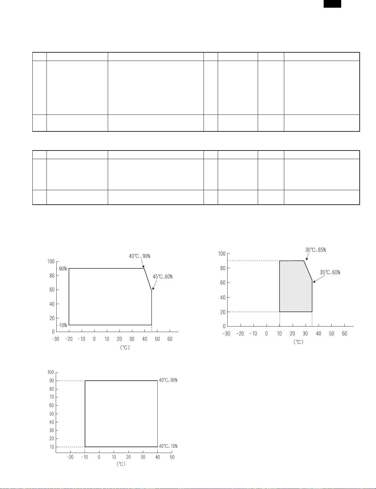
2. Environment conditions
A. Transport condition
(1) Transport conditions
Humidity (%)
Temperature
(2) Storage conditions (packed conditions)
B. Use conditions
Use environment
conditions
Humidity (%)
Temperature
C. Life (packed conditions)
Photoconductor drum (36 months from the production month)
Developer, toner (24 months from the production month)
Humidity (%)
Temperature
3 – 1
Page 14
DM-2000
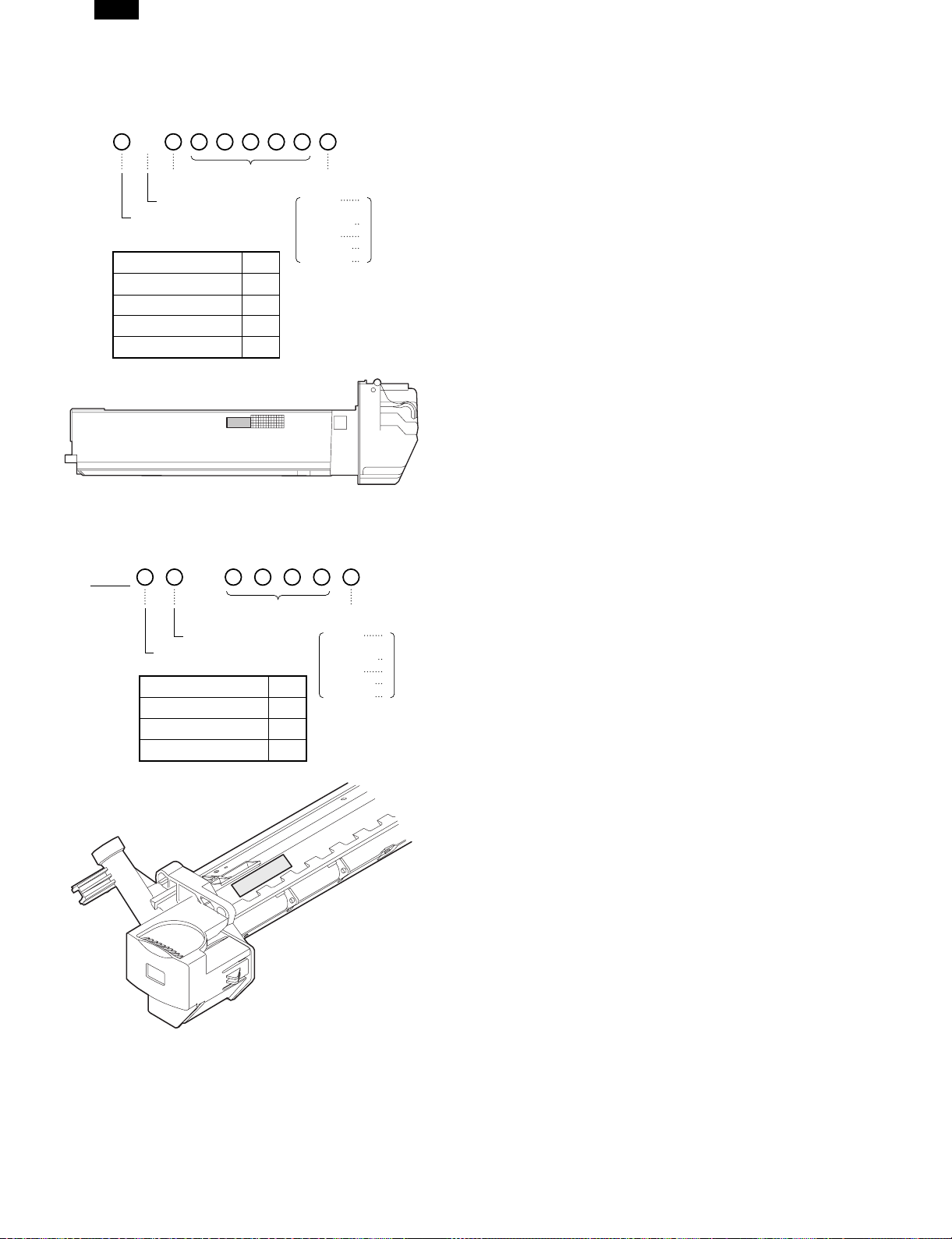
3. Production number identification
<Developing cartridge>
The label on the drum cartridge shows the date of production.
B
Destination
(∗)
Indicates production in China.
The end digit of production year
∗: Destination
Division No.
Serial number
(00001-99999)
Production
month
January
~
September
October
November
December
1
~
9
0
X
Y
Japan option 1
Ex option 2
Japan, same pack 6
Ex, same pack 7
<Drum cartridge>
The label on the drum cartridge shows the date of production.
Ver. A
1
Serial number (for each
month) (00001-99999)
Factory
The end digit of production year
Division No.
Ex production 1
Option 2
Same pack 3
Production
month
January
~
September
October
November
December
1
~
9
0
X
Y
3 – 2
Page 15
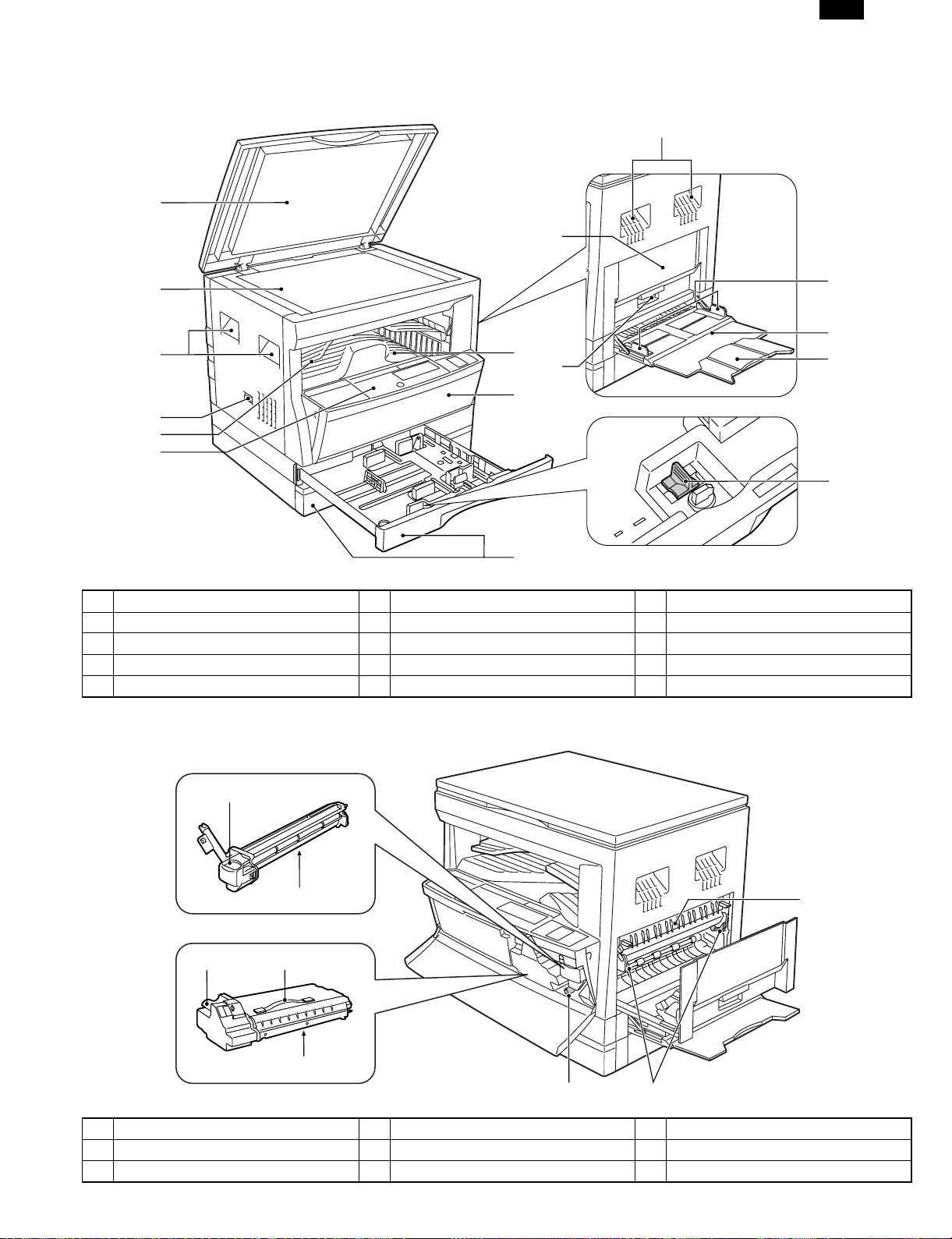
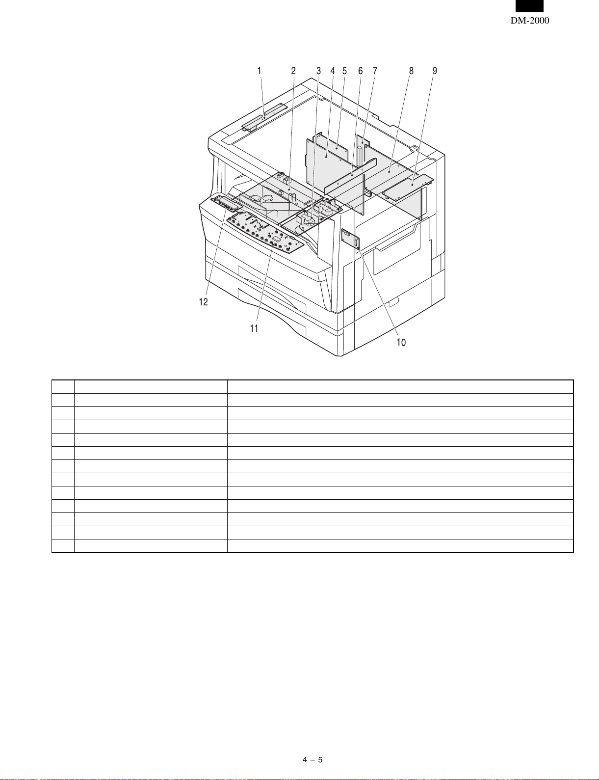
[4] EXTERNAL VIEWS AND INTERNAL STRUCTURES
1. Appearance
1
10
DM-2000
3
2
3
7
11
8
4
5
6
9
1 Platen cover 2 Original table 3 Handles
4 Power switch 5 Job separator tray 6 Operation panel
7 Paper output tray 8 Front cover 9 Paper trays
10 Side cover 11 Side cover handle 12 Bypass tray guides
13 Bypass tray 14 Bypass tray extension 15 Charger cleaner
12
13
14
15
2. Internal
1
2
3
4
5
6
1 Drum cartridge handle 2 Drum cartridge 3 TD cartridge lock release lever
4 TD cartridge strap 5 TD cartridge 6 Roller rotating knob
7 Fusing unit release levers 8 Paper guide
7
8
4 – 1
Page 16
DM-2000
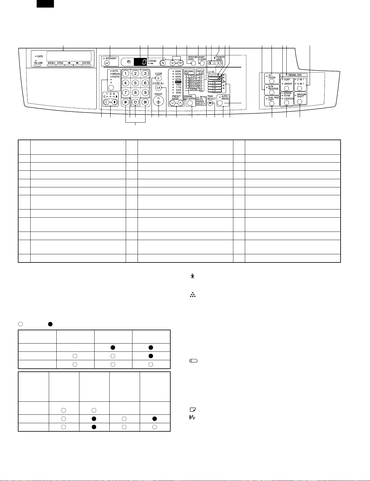
3. Operation Section
6
7
1
Operation panel and keys for printer
1
features
2345
21
19
20
Not used for the copier features.
22
2 INTERRUPT key and indicator 3 Copy quantity display
23 24 25
26
4 ZOOM indicator 5 Copy ratio display key 6 Zoom keys
7 PAPER SIZE ENTER key 8 AUDIT CLEAR key 9 PAPER SIZE indicators
10 Alarm indicators ∗2 11 POWER SAVE indicator ∗1 12 SPF indicator
13 Output tray full indicator 14 B/W REVERSE key and indicator 15 XY-ZOOM key and indicator
16 SORT/GROUP key and indicators 17 ORIGINAL DATA indicator 18 2 IN 1 / 4 IN 1 key and indicators
AUTO/MANUAL/PHOTO key and
19
indicators
20 Light and dark keys and indicators 21 Numeric keys
22 Zero key 23 CLEAR key 24 START key and indicator
25 CLEAR ALL key 26
PRESET RATIO selector keys and
indicators
28 AUTO PAPER SELECT indicator 29 TRAY SELECT key 30 AUTO IMAGE key and indicator
Paper feed location/misfeed location
31
indicators
32 DUAL PAGE COPY key and indicator 33 ERASE key and indicators
34 MARGIN SHIFT key and indicator
891011
27 28
13
12
29
30 31
27
14
15 16 17
32
33 34
18
ORIGINAL SIZE ENTER key and
indicators
∗1
ON: Indicates that the machine is in the energy saving (pre-heat)
mode.
Blink: Indicates that the machine is in the process of resetting from the
energy saving mode or just after supplying the power. (During
warmup)
OFF: Indicates that resetting from the energy saving mode is com-
pleted and that the fusing temperature is in ready state.
The combinations of the above display lamps are as follows:
( = ON, = OFF)
Lamp
Pre-heat lamp Blink
Ready lamp
Other lamps
Lamp
Pre-heat
lamp
Ready lamp
Other lamps
Immediately after
power ON
Energy
saving mode
(Pre-heating)
Energy
saving mode
(Auto power
shut off)
Ready Copying
Resetting
from energy
saving mode
Blink Blink
Copy is
started during
resetting from
energy
saving mode
∗2
Maintenance lamp
When the set count number (set by the simulation) is reached,
the lamp lights up. The machine does not stop.
TD cartridge replacement required indicator
When toner density is lower than a specified level, the TONER
DEVELOPER CARTRIDGE REPLACEMENT indicator lights up
to warn the user.
If toner is not added after approximately 300 sheets are copied,
the indicator starts blinking and machine starts to supply toner.
(Toner Developer cartridge replacement indicator keeps lighting
up)
If toner density is not back to specific level after two minutes, the
READ indicator goes out and Toner Developer indicator starts
blinking, and the copier stops.
Photoconductor cartridge replacement lamp
When the copy count reaches 29,000 after installing a Photoconductor cartridge, the lamp lights up.
When 1,000 copies are made after that, the lamp blinks instead
of lighting. The machine does not stop.
Press and hold the clear key for 5 sec in the user simulation
mode to display the remaining life of the photoconductor cartridge
in 3 digits x 2 lines on the copy quantity display.
Paper required indicator
Misfeed indicator
4 – 2
Page 17
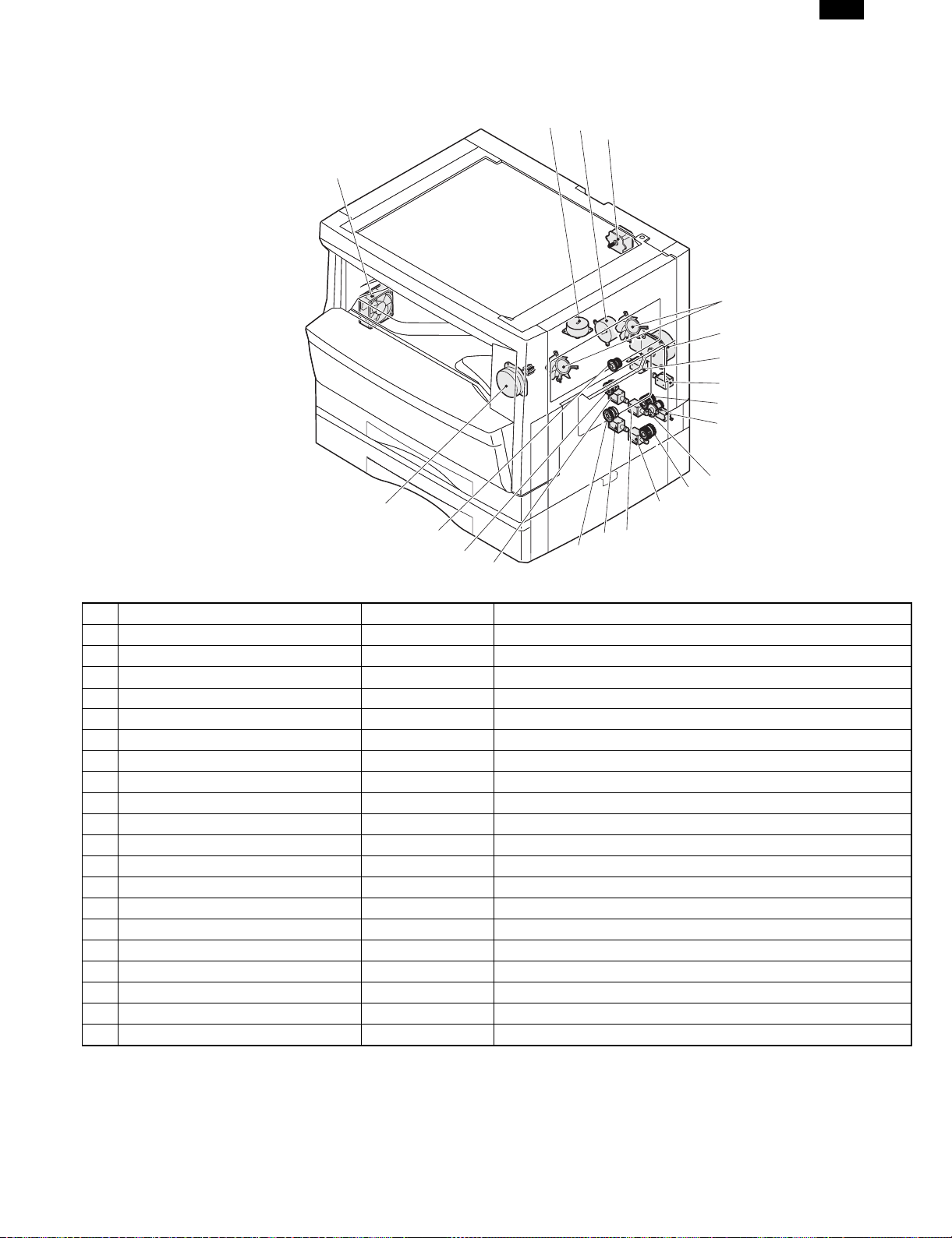
4. Motor, solenoid, clutch
DM-2000
2
3
4
1
5
6
7
8
9
10
11
12
20
13
19
18
17
No. Name Code Function, operation
1 Exhaust fan motor VFM Cools the inside of the machine.
2 Shifter motor SHTM Shifts the paper exit tray.
3 Toner motor TM Toner supply
4 Mirror motor MRM Drives the optical mirror base (scanner unit).
5 Cooling fan motor CFM Cools the inside of the machine.
6 Main motor MM Drives the machine.
7 Paper feed solenoid CPFS1 Solenoid for paper feed from cassette
8 Resist roller solenoid RRS Resist roller rotation control solenoid
9 Manual paper feed clutch MPFC Drives the manual paper feed roller.
10 Manual paper feed solenoid MPFS Manual paper feed solenoid
11 Manual paper transport clutch MPTC Drives the manual paper transport roller.
12 Second tray transport clutch CPFC2 Drives the second tray transport roller.
13 Second tray transport solenoid FSOL2 Second tray transport solenoid
14 First tray transport solenoid FSOL1 First tray transport solenoid
15 Second tray paper feed solenoid PSOL2 Second tray transport solenoid
16 Paper feed clutch CPFC2 Drives the cassette paper feed roller.
17 First tray paper feed solenoid PSOL1 First tray transport solenoid
18 First tray paper feed clutch CPFC1 Drives the first tray transport roller.
19 PS clutch RRC Drives the resist roller
20 Job separator Motor LFTM Drives the Job-separator
16
15
14
4 – 3
Page 18
DM-2000
5. Sensor, switch
23
123
20
21
22
4
5
6
7
8
9
10
11
12
13
14
15
16
17
18
19
No. Name Code Function, operation
1 Mirror home position sensor MHPS Detects the mirror (scanner unit) home position.
2 Document size sensor DSIN Paper size detection
3 Toner density sensor TCS Toner quantity detection
4 Paper exit sensor (paper exit side) POD1 Detects paper exit.
5 OC open/close sensor DOC COVER OC and SPF open close detection
6 Right door switch DSWR Side door open/close detection
7 Paper full sensor P FULL Paper exit tray section full detection <For JOB separator>
8 Lift sensor LFTHP Paper feed tray lift up detection <For JOB separator>
9 Lower limit sensor JTRAY Job separator tray lower limit detection
10 Paper exit sensor (DUP side) PDPX Paper transport detection
11 Shifter home position sensor SFTHP Shifter home position detection
12 Thermistor RTH Fusing section temperature detection
13 Thermostat Fusing section abnormally high temperature detection
14 1st tray detection switch CSD1 1st tray detection
15 Paper in PIN Paper transport detection
16 2nd tray detection switch CSD2 2nd tray detection
17 Manual sensor MPED Manual transport detection
Second cassette door open/close
18
sensor
19 Second cassette paper entry sensor PPD2 Paper transport detection
20 First tray paper empty sensor CSS1 First tray paper empty detection
21 Second tray paper empty sensor CSS2 Second tray paper empty detection
22 Drum reset switch DRST New drum detection switch
23 Power switch MAIN SW Turns ON/OFF the main power source.
DRS2 Second cassette door open/close detection
4 – 4
Page 19
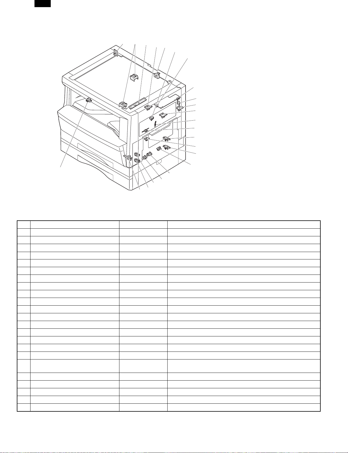
6. PWB unit
DM-2000
12
1234965
11
78
10
No. Name Function, operation
1 Copy lamp Inverter PWB Copy lamp control
2 Power PWB AC power input/DC power control
3 High voltage PWB High voltage control
4 Printer control PWB Printer control
5 Network Board Network system interface
6 CCD sensor PWB Image scanning
7 Motor PWB
8 Main PWB (MCU) Machine control/Image process
9 Paper exit interface PWB Paepr exit, finishing control
10 Tray interface PWB Paper tray control
11 Operation main PWB Operation panel input/Display, operation panel section control
12 LCD PWB Printer and FAX status display
4 – 5
Page 20
DM-2000
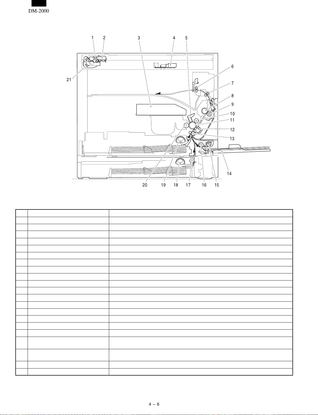
7. Cross sectional view
12 3 45
6
21
7
8
9
10
11
12
13
14
15
1617181920
No. Name Function/Operation
1 Copy lamp Image radiation lamp
2 Copy lamp unit Operates in synchronization with No. 2/3 mirror unit to radiate documents sequentially.
3 LSU unit Converts image signals into laser beams to write on the drum.
4 Lens unit Reads images with the lens and the CCD.
5 MC holder unit Supplies negative charges evenly on the drum.
6 Paper exit roller Used to discharge paper.
7 Transport roller Used to transport paper.
8 Upper heat roller Fuses toner on paper (with the teflon roller).
9 Lower heat roller Fuses toner on paper (with the silicon rubber roller).
10 Waste toner transport roller Transports waste toner to the waste toner box.
11 Drum unit Forms images.
12 Transfer charger unit Transfer images (on the drum) onto paper.
13 Resist roller Takes synchronization between the paper lead edge and the image lead edge.
14 Manual paper feed tray Manual paper feed tray
15 Manual paper feed roller Picks up paper in manual paper feed.
16 Manual transport roller Transports paper from the manual paper feed port.
17 2nd tray paper transport roller Transports paper from the 2nd tray
2nd tray paper feed roller (semi-circuit
18
roller)
1st tray paper feed roller (semi-circular
19
roller)
20 MG roller Puts toner on the OPC drum.
21 No. 2/3 mirror unit Reflects the images from the copy lamp unit to the lens unit.
Picks up paper from 2nd tray
Picks up paper from the 1st tray
4 – 6
Page 21
DM-2000
[5] UNPACKING AND INSTALLATION
1. Installing conditions
1) Copier installation
Do not install your copier in areas that are:
● damp, humid, or very dusty
● exposed to direct sunlight
● poorly ventilated
● subject to extreme temperature or humidity changes, e.g., near
an air conditioner or heater.
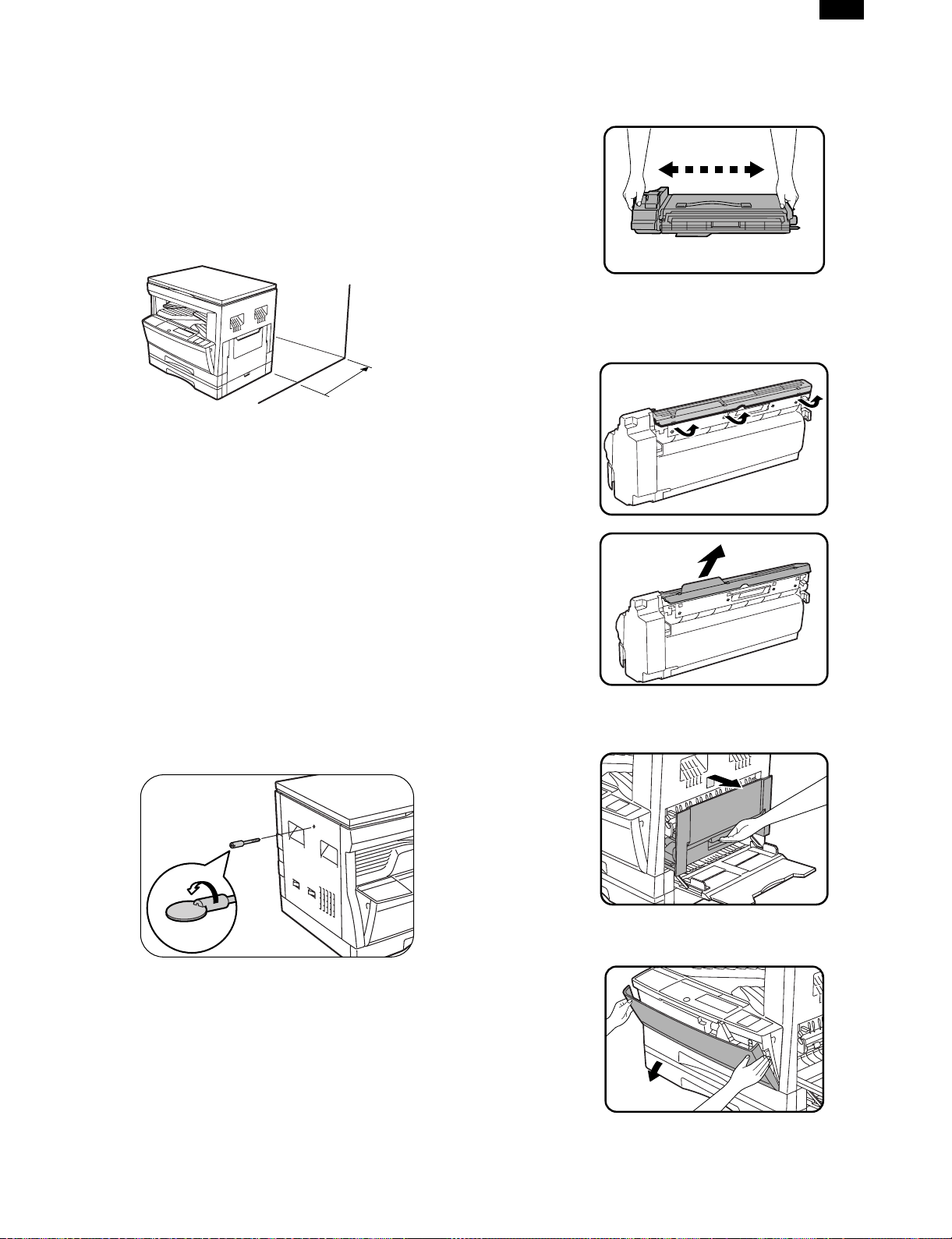
● Be sure to allow the required space around the machine for servicing and proper ventilation.
4" (10 cm)
2) Power source
● Use an exclusive-use power outlet. If the power plug of this
machine is inserted into a power outlet commonly used with
other illumination units, flickers of the lamp may be result. Use
a power outlet which is not used commonly with any illumination
units.
● Avoid complex wiring.
3) Grounding wire connection.
● To avoid danger, be sure to connect a grounding wire. If no
grounding wire is connected and a leakage occurs, a fire or an
electric shock may be result.
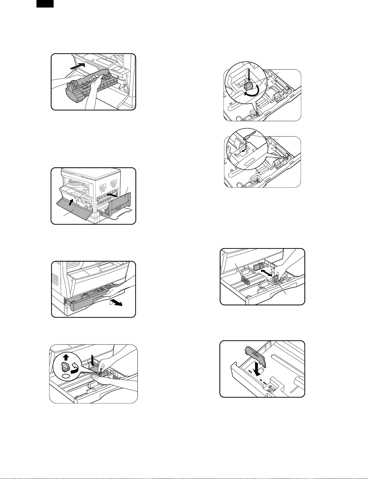
3. Installation of developing cartridge
1) Remove the new TD cartridge from the bag. Hold the cartridge on
both sides and shake it horizontally four or five times.
4 or 5 times
2) Remove the protective cover from the TD cartridge by unlatching
three cover hooks from the holes on the cartridge and then pulling
the cover in the direction indicated by the arrow in the illustration.
2. Removal of protective material and
fixing screw
1) Remove all tapes and protective material.
● Remove all tapes, then open the document cover and remove
the protective material of sheet shape
2) Remove the fixing screw.
● Use a coin to remove the fixing screw.
● The fixing screw is required when transporting the machine.
Keep it in the tray. (Refer to the later description.)
3) Open the bypass tray. Lift slightly on the side cover and slide the
cover out until it stops.
4) Push gently on both sides of the front cover to open the cover.
5 – 1
Page 22
Front guide
Left guide
DM-2000
5) Gently insert the TD cartridge along the guides until it locks in
place.
Note: If dirt or dust is adhered to the TD cartridge, remove it
before installing the cartridge.
6) Close the front cover by pushing both sides with your hands and
then close the side cover by pressing the handle on the cover.
The indicator will go out.
Cautoion: When closing the covers, be sure to close the front
cover securely and then close the side cover. If the
covers are closed in the wrong order, the covers may
be damaged.
B
3) Store the fixing pin and the fixing screw in the tray.
● Store the fixing screw which was removed in the above procedure 2 and the fixing screw which was removed in procedure 2
of 2.
● Removal of protective material and fixing screw in the storage
place in the tray.
Pressure
plate
lock
Screw
A
4. Removal and storage of fixing screw
1) Gently lift and pull out the paper tray until it stops.
2) Hold the paper pressure plate and turn the fixing screw in the
arrow direction.
5. Changing the copy paper size in the
tray
1) Gently lift and pull out the paper tray until it stops.
2) Push the pressure plate down until it locks in place.
3) Squeeze the lock lever of the front guide and slide the front guide
to match the width of the paper.
4) Move the left guide to the appropriate slot as marked on the tray.
● When using 11" ×17" copy paper, store the left guide in the slot
at the left front of the paper tray.
5) Load copy paper into the tray.
6) Place the appropriate label to indicate the selected paper size into
the recess on the right front side of the paper tray.
7) Push the paper tray firmly back into the DM System.
8) Turn the power switch on.
5 – 2
Page 23
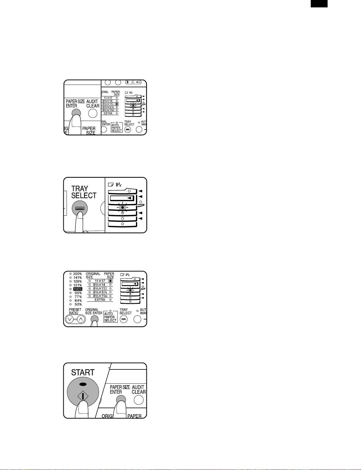
9) To set the selected paper size, press the PAPER SIZE ENTER
key.
● The selected paper feed location indicator will blink and the corresponding paper size (which is currently set) indicator will light
up steadily. All other indicators will go out.
Note: For paper size setting, ensure that the COPY mode has
been selected. However, if copying, printing or facsimile
printing is being performed, paper size setting cannot be
made even in the COPY mode.
10) Use the TRAY SELECT key to select the paper tray of which the
paper size has been changed.
● Each time the TRAY SELECT key is pressed, a paper tray will
be indicated with a blinking paper feed location indicator.
11) Use the ORIGINAL SIZE ENTER key to select the paper size
which is set.
● Each time the ORIGINAL SIZE ENTER key is pressed, a paper
size will be indicated with a paper size indicator.
DM-2000
6. Installing the printer driver
To use this printer with your computer, you must install the printer
driver.
Install the printer driver using the supplied SHARP Software CD-ROM.
This kit is supplied with the following printer drivers:
● PCL6 for Windows 95/98
● PCL6 for Windows NT 4.0
● PCL5e for Windows 95/98
● PCL5e for Windows NT 4.0
Note: ● It is recommended that you install the PCL6 printer driver. If
you have a problem printing from older software using the
PCL6 driver, remove it and install the PCL5e driver.
● The printer driver data in the CD-ROM can be copied to floppy disks.
1. Double-click “My Computer”, “Dm2000” and “Makedisk”.
2. Double-click “Makedisk.exe”.
3. Follow the on-screen instructions.
Before installation, make sure that:
● You read the README.TXT file which is contained on the SHARP
Software CD-ROM. This file contains the information and restrictions
for using the printer.
● The printer is connected properly with the computer or network.
● The printer is loaded with paper.
● The printer is turned on and on-line (the ON LINE light is lit).
● You quit all application software that is running on your computer.
● Your computer meets the following hardware and software require-
ments:
Computer Type
Operating System Windows 95, Windows 98, Windows NT 4.0
CPU Windows 95: 486SX or better
RAM Windows 95: 8 MB or more (12 MB or
This procedure uses the following drive name in examples:
Drive R: CD-ROM drive (holds the CD-ROM containing the printer
Change the drive name as required according to your environment.
IBM PC/AT or compatible computer equipped
with a bi-directional parallel interface and CDROM drive
Windows 98: 486DX/66 MHz or better
(Pentium or better is
recommended.)
Windows NT 4.0: 486/25 MHz or better
more is recommended.)
Windows 98: 16 MB or more (32 MB or
more is recommended.)
Windows NT 4.0: 16 MB or more
drivers)
12) Press the START key and then the PAPER SIZE ENTER key.
● To change the paper size setting of another tray, repeat steps
10) to 11) after pressing the START key.
A. Installing onto Windows 95
This printer is compatible with plug & play. If your computer is incompatible with plug & play or if you want to use this printer as a network
printer, refer to “Installing onto Windows 95/98 without Using the Plug
& Play Function”.
1) Turn the computer on and start Windows 95.
Note: Depending on which version of Windows you are using, the
display examples in this step may differ from those on your
system.
● Either the “Update Device Driver Wizard” window or the “New
Hardware Found” window may appear automatically.
Note: If neither the “Update Device Driver Wizard” window nor
the “New Hardware Found” window appear, refer to “Installing Windows 95/98 without Using the Plug & Play
Function”.
5 – 3
Page 24
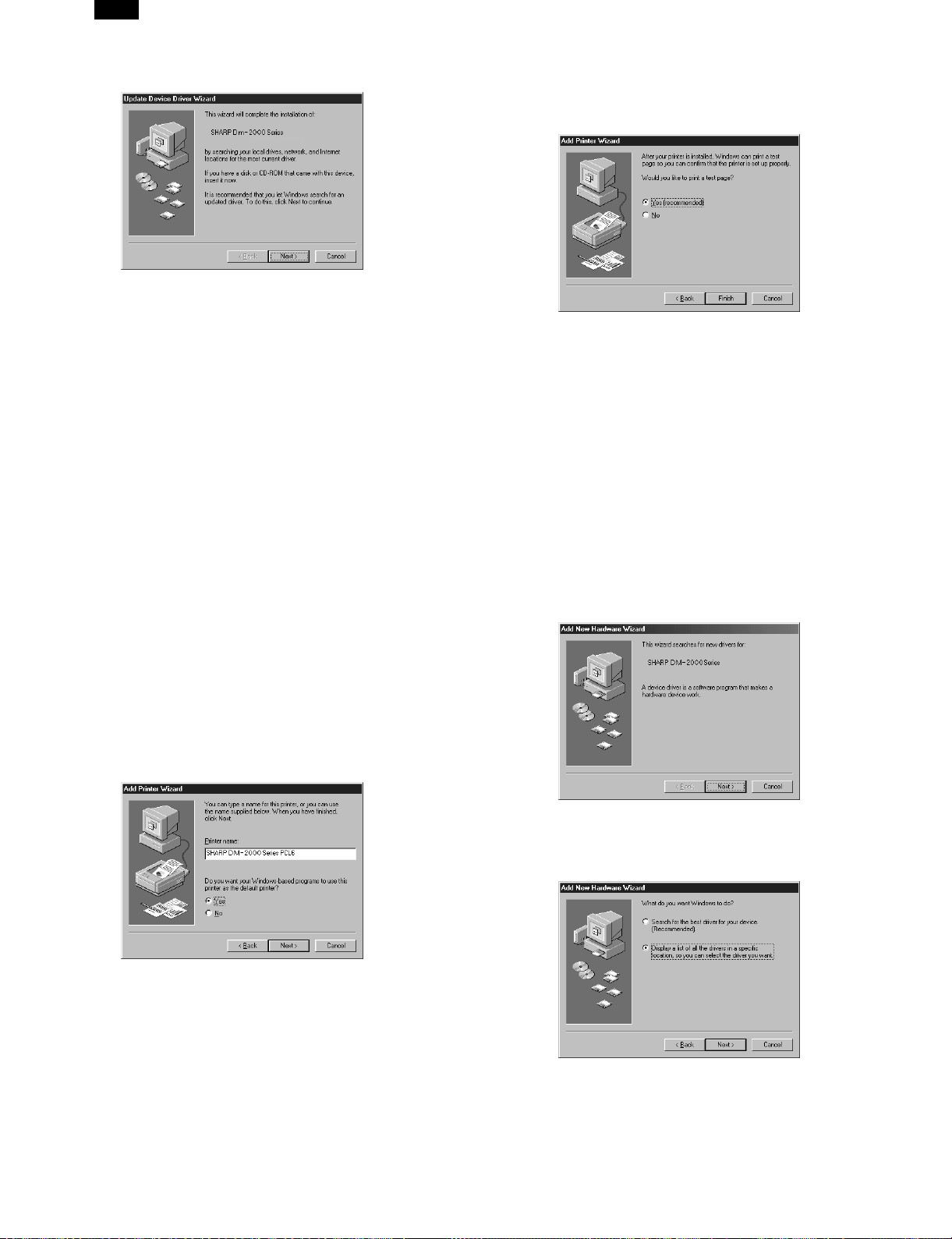
DM-2000
● If the “Update Device Driver Wizard” window appears, click the
[Next] button and proceed to step 2).
● If the “New Hardware Found” window appears, perform the fol-
lowing steps:
<1> Choose “Driver from disk provided by hardware manufac-
turer” and click the [OK] button.
<2> When the “Install From Disk” window appears, insert the
SHARP Software CD-ROM into the CD-ROM drive, type
R:\English\WinXX and click the [OK] button.
<3> Choose the appropriate printer driver from those listed below
and click the [OK] button.
● PCL6 Printer Driver:SHARP DM-2000 Series PCL6
● PCL5e Printer Driver:SHARP DM-2000 Series PCL5e
Note: It is recommended that you install the PCL6 printer driver.
If you have a problem printing from older software using
the PCL6 driver,remove it and install the PCL5e driver.
<4> Proceed to step 5).
2) Search for the printer driver by clicking [Other Locations...] button.
3) Insert the SHARP Software CD-ROM into the CD-ROM drive, type
R:\English\WinXX and click the [OK] button.
4) After Windows finds the printer driver, click the [Finish] button to
continue the installation.
Note: In this step the PCL6 printer driver is installed automat-
ically. If you want to install the PCL5e printer driver, refer
to “Installing onto Windows 95/98 without Using the Plug &
Play Function”.
5) Set the printer name.
<1> If you want to change the printer name, enter a new name
in the space provided.
<2> If the program displays, “Do you want your Windows-based
programs to use this printer as the default printer?”, check
“Yes”.
<3> Click the [Next] button.
6) Print a test page by clicking the [Finish] button.
Note: If you check “No” and click the [Finish] button, the printer
does not print a test page after the installation.
● The printer driver installation begins.
● If the “Insert Disk” window appears, perform the following steps:
<1> Click the [OK] button.
<2> When the “Copying Files” window appears, type
R:\English\WinXX and click the [OK] button.
7) When the test page is printed properly, click the [Yes] button.
● The printer is ready for printing.
B. Installing onto Windows 98
This printer is compatible with plug & play. If your computer is incompatible with plug & play or if you want to use this printer as a network
printer, refer to “Installing onto Windows 95/98 without Using the Plug
& Play Function”.
1) Turn the computer on and start Windows 98.
● The “Add New Hardware Wizard” window appears automat-
ically, click the [Next] button.
Note: If the “Add New Hardware Wizard” window does not ap-
pear in this step, refer to “Installing onto Windows 95/98
without Using the Plug& Play Function”.
5 – 4
2) Display a list of all the printer drivers by checking “Display a list
of all the drivers in a specific location, ...” and clicking the [Next]
button.
Page 25

3) Click the [Have Disk...] button.
4) Insert the SHARP Software CD-ROM into the CD-ROM drive, type
R:\English\WinXX, and click the [OK] button.
5) Choose the appropriate printer driver from those listed below and
click the [Next] button.
● PCL6 Printer Driver: SHARP DM-2000 Series PCL6
● PCL5e Printer Driver: SHARP DM-2000 Series PCL5e
Note: It is recommended that you install the PCL6 printer driver.
If you have a problem printing from older software using
the PCL6 driver,remove it and install the PCL5e driver.
DM-2000
C. Installing onto Windows 95/98 without Using the
Plug & Play Function
Computers using Windows 95 or Windows 98 that are compatible with
plug & play can install the printer driver automatically. However, if your
computer is incompatible with plug & play, or if you want to use this
printer as a network printer, follow the procedure in this section.
The following steps use Windows 98 in display examples.
1) Turn the computer on and start Windows 95/98.
2) Click the Start menu, point to “Settings”, and choose “Printers”.
3) When the “Printers” window appears, double-click the “Add
Printer” icon.
4) Click the [Next] button.
5) If the screen for choosing the connection method appears, choose
the connection method and click the [Next] button.
Note: This screen appears only when the computer is connected
to a network.
● When the printer is directly connected to the computer, choose
“Local printer”.
Otherwise, choose “Network printer”.
If you choose “Network printer” you must specify a network path
or queue name.
Contact your network administrator for details.
The following steps use the example of a local printer.
6) After Windows finds the printer driver, click the [Next] button to
continue the installation.
7) Print a test page by clicking the [Finish] button.
Note: If you check “No” and click the [Finish] button, the printer
does not print a test page after the installation.
● The printer driver installation begins.
8) When the test page is printed properly, click the [Yes] button.
● The printer is ready for printing.
6) Click the [Have Disk...] button.
7) Insert the SHARP Software CD-ROM into the CD-ROM drive, type
R:\English\WinXX, and click the [OK] button.
8) Choose the appropriate printer driver from those listed below and
click the [Next] button.
● PCL6 Printer Driver: SHARP DM-2000 Series PCL6
● PCL5e Printer Driver: SHARP DM-2000 Series PCL5e
Note: It is recommended that you install the PCL6 printer driver.
If you have a problem printing from older software using
the PCL6 driver,remove it and install the PCL5e driver.
5 – 5
Page 26

DM-2000
9) Choose the port and click the [Next] button.
Note: This screen appears only if you selected “Network printer”
in step 5).
D. Installing onto Windows NT 4.0
1) Turn the computer on and start Windows NT.
2) Click the Start menu, point to “Settings”, and choose “Printers”.
3) When the “Printers” window appears, double-click the “Add
Printer” icon.
4) Choose “My Computer” or “Network printer server” and click the
[Next] button.
● The following steps use “My Computer” as an example.
For more information about using this printer as a network
printer, refer to the Windows NT 4.0 networking documentation.
5) Check the checkbox for the port you are using and click the [Next]
button.
10) Set the printer name.
<1> If you want to change the printer name, enter a new name
in the space provided.
<2> If the program displays, “Do you want your Windows-based
programs to use this printer as the default printer?”, check
“Yes”.
<3> Click the [Next] button.
11) Print a test page by clicking the [Finish] button.
Note: If you check “No” and click the [Finish] button, the printer
does not print a test page after the installation.
● The printer driver installation begins.
6) Click the [Have Disk...] button.
7) Insert the SHARP Software CD-ROM into the CD-ROM drive, type
R:\English\WinNT and click the [OK] button.
12) When the test page is printed properly, click the [Yes] button.
● The printer is ready for printing.
8) Choose the appropriate printer driver from those listed below and
click the [Next] button.
● PCL6 Printer Driver: SHARP DM-2000 Series PCL6
● PCL5e Printer Driver: SHARP DM-2000 Series PCL5e
Note: It is recommended that you install the PCL6 printer driver.
If you have a problem printing from older software using
the PCL6 driver,remove it and install the PCL5e driver.
5 – 6
Page 27

9) Set the printer name.
<1> If you want to change the printer name, enter a new name
in the space provided.
<2> If the program displays, “Do you want your Windows-based
programs to use this printer as the default printer?”, check
“Yes”.
<3> Click the [Next] button.
10) Make the appropriate settings for your environment.
● When using print sharing, choose “Shared” and enter a share
name. If necessary for your environment, select Windows 95
from the list of operating systems.
● If you are not using shared printing, choose “Not shared”.
DM-2000
7. Expansion memory installation
Memory expansion realizes the following effects.
● Increased processing speed of outline fonts or complex graphic data.
● Shorter release time from a printing job of the computer.
● Allows high resolution printing.
● Complex data can be printed without data loss error or memory full
error.
Extend the pawls, insert an expansion memory, and engage the pawls
with the notches.
8. Print server card installation
Remove the dummy cover, insert the print server card into the connector of the printer PWB and fix it with the screw of the dummy cover. At
that time, cut off the notched section in the rear cabinet with nippers.
(Use nippers so that the cut surface is flat.)
Dummy cover
After making the settings on this screen, click the [Next] button.
11) Print a test page by clicking the [Finish] button.
Note: If you check “No” and click the [Finish] button, the printer
does not print a test page after the installation.
● The printer driver installation begins.
12) When the test page is printed properly, click the [Yes] button.
● The printer is ready for printing.
E. Changing Printer Configuration Settings
After installing the printer driver use the procedure in this section to
change the printer configuration settings. Also refer to the print driver
help for more information.
1. Click the Start menu, point to “Settings”, and choose “Printers”.
2. Right-click the appropriate printer and choose “Properties” fromthe menu.
3. Click the Configuration tab and change the printer settings.
5 – 7
Page 28

DM-2000
[6] ADJUSTMENTS
1. Adjustment item list
Section Adjustment item Adjustment procedure/SIM No.
A Process section
B Mechanism section
C Image density adjustment (1) Copy mode SIM 46-1
(1) Developing bias voltage output adjustment
(2) Grid bias voltage adjustment
(1) Image lead edge position adjustment SIM 50-1/SIM 50-10
Main scanning direction (FR direction)
(2)
distortion balance adjustment
Main scanning direction (FR direction)
(3)
distortion adjustment
Sub scanning direction (scanning direction)
(4)
distortion adjustment
Main scanning direction (FR direction)
(5)
magnification ratio adjustment
Sub scanning direction (scanning direction)
(6)
magnification ratio adjustment
(7) Off center adjustment
OC (SPF) open/close detection position
(8)
adjustment
(9) Original sensor adjustment SIM 43-3
No. 2/3 mirror base unit installing position
adjustment
Copy lamp unit installing position adjustment
Rail height adjustment
Winding pulley position adjustment
SIM 48-1
a OC mode in copying (SIM 48-2)
b SPF mode in copying (SIM 48-5)
a OC mode (SIM 50-13)
b SPF mode (SIM 50-16)
2. Copier adjustment
A. Process section
(1) Developing bias voltage adjustment
Note: ● Use a digital multi-meter with an internal resistance of 10 MΩ
or more.
1) Set the digital multi-meter range to DC700V.
2) Put the test rod of the digital multi-meter on the developing bias
voltage output check pin.
3) Turn on the power.
4) Adjust the adjustment volume VR31 so that the output voltage is
within the specified range shown below.
(2) Grid bias voltage adjustment
Note: ● Use a digital multi-meter with an internal resistance of 10MΩ
or more.
1) Set the digital multi-meter range to DC700V.
2) Put the test rod of the digital multi-meter on the grid bias voltage
output check pin.
3) Turn on the power.
4) Adjust the adjustment volumes (VR51, VR52) so that the output
voltage is within the specified range. (The voltage is outputted in
the grid bias high output mode during warming up, and in the grid
bias low output mode after completion of warming up.)
5) Adjust the adjustment volume VR51/VR52 so that the output voltage is within the specified range shown below.
<Adjustment specification>
Mode Specification
Developing bias voltage DC-400 ± 8V VR31
<Adjustment specification>
Mode Specification
Grid bias LOW DC-400 ± 20V VR52
Grid bias HIGH DC-525 ± 10V VR51
6 – 1
Page 29

B. Mechanism section
(1) Image lead edge position adjustment (SIM 50-1/SIM 50-10)
a. OC image lead edge position adjustment
Note: In advance to this adjustment, the sub scanning magnification
ratio adjustment must be performed.
1) Set a scale on the OC table as shown below.
DM-2000
8) Measure the image loss R of the copied image. Enter the set
value of the image scanning lead edge position (Exposure display
<AUTO> ON) again.
● 1 step of the set value corresponds to about 0.127 mm shift.
● Calculate the set value from the formula below.
99 - R/0.127 (mm) = Image loss set value <R: Image loss measurement value (mm)>
5mm
0mm
5
10
2) Make a copy.
3) Check the copy output. If necessary, perform the following adjustment procedures.
4) Execute SIM 50-1.
5) Set the OC lead edge position set value (Exposure display
<AUTO> ON) to “99.”
The OC image scanning start position is shifted inside the document edge.
6) Set the main cassette lead edge void adjustment value (Exposure
display <PHOTO> ON) * to “1.”
The lead edge void becomes the minimum.
7) Set the print start position value (Exposure display <EXP1> ON)
to “99” and make a copy.
The print start position is shifted inside the document edge.
5mm
5
4mm
10
*The dimension varies depending on the model.
* The scanning edge is set.
(A line may be printed by scanning the document edge.)
Example: 99 - 4/0.127 = 99 - 31.5 = about 67
Note: If the set value is not obtained from the above formula, per-
form the fine adjustment.
9) Measure the distance H between the paper lead edge and the
image print start position. Set the image print start position set
value (Exposure display <EXP1> ON) again.
● 1 step of the set value corresponds to about 0.127 mm shift.
● Calculate the set value from the formula below.
99 - H/0.127 (mm) = Image print start position set value <H: Print
start position measurement value (mm)>
0mm
5
10
*Fit the print edge with the paper edge, and perform the
lead edge adjustment.
0mm
6 – 2
Example: 99 - 5/0.127 = 99 - 39.4 = about 59
Note: If the set value is not obtained from the above formula, per-
form the fine adjustment.
Page 30

DM-2000
10) Set the main cassette lead edge void adjustment value (Exposure
display <PHOTO> ON)* again.
● 1 step of the set value corresponds to about 0.127 mm shift.
● Calculate the set value from the formula below.
B/0.127 (mm) = Lead edge void adjustment value <B: Lead edge
void (mm)>
2.5mm
5
10
Example: When setting the lead edge void to 2.5 mm:
2.5 /0.127 = about 20
Note: If the set value is not obtained from the above formula, per-
form the fine adjustment.
∗ Second cassette lead edge void adjustment: Exposure display
<AUTO + MANUAL + PHOTO>
Multi bypass tray lead edge void adjustment: Exposure display
<MANUAL + PHOTO>
<Adjustment specification>
Adjustment
mode
OC image
lead edge
position
SIM LED
AUTO
Set
value
99 –
R/0.127
Main
cassette
lead edge
PHOTO
void
Second
cassette
lead edge
void
50-1
AUTO +
MANUAL
+ PHOTO
B/0.127
Multi
bypass tray
lead edge
MANUAL
+ PHOTO
void
Print start
position
EXP1
99 –
H/0.127
b. SPF image lead edge position adjustment
1) Set a scale on the OC table as shown below.
Note: Since the printed copy is used as a test chart, put the scale
in parallel with the edge lines.
2) Make a copy, Then use the copy output as an original to make an
SPF copy again.
3) Check the copy output. If necessary, perform the following adjustment procedures.
2.5mm
Spec value
Lead edge
1 ∼ 4 mm
Set
range
1 ∼ 99
4) Execute SIM 50-1.
5) Set the SPF lead edge position set value (Exposure display
<MANUAL> ON) so that the same image is obtained as that obtained in the previous OC image lead edge position adjustment.
<Adjustment specification>
Adjustment
mode
SPF image
lead edge
position
SIM LED
50-1 MANUAL
Set
value
1 step:
0.127
mm shift
Spec value
Lead edge
void: 6 mm
or less
Set
range
1 ∼ 99
c. Rear edge void adjustment
1) Set a scale as shown in the figure below.
A4(8.5" x 11")
Paper rear edge
2) Set the document size to A4 (8.5" × 11"), and make a copy at
100%.
3) If necessary, perform the following adjustment procedure.
Void amount (Standard value: 4mm or less)
Scale image
Paper rear edge
4) Execute SIM 50-1 and set the density mode to AUTO + PHOTO
(Rear edge void).
The currently set adjustment value is displayed.
5) Enter the set value and press the start key.
The correction value is stored and a copy is made.
<Adjustment specification>
Mode SIM LED
Rear edge void SIM 50-1
∗1
Second print
surface rear
edge void
∗1
SIM 50-1
∗2
AUTO +
PHOTO
EXP 5
Set
value
1 step:
0.127
mm shift
Specifi-
cation
4 mm
or less
4 mm
or less
Set
range
1 ∼ 99
∗1: DM-2000 cannot be used.
∗2: Set to S → D mode before execution
d. Paper off center adjustment
1) Execute SIM 50-1 and set the density mode of AUTO + MANUAL
(Left edge void) to 1.
2) Set a test chart (UKOG-0089SCZZ or UKOG-0123FCZZ) on the
document table.
3) Select a paper feed port and make a copy.
Compare the copy and the test chart. If necessary, perform the
following adjustment procedure.
6 – 3
Page 31

4) Execute SIM 50-10.
After completion of warmup, shading is performed and the currently set off center adjustment value of each paper feed port is
displayed.
5) Enter the set value and press the start key.
The correction value is stored and a copy is made.
<Adjustment specification>
Mode SIM LED Set value
Paper off
center
Second
print
surface
off-center
∗1: DM-2000 cannot be used.
∗ When SIM 48-01 (AE) is executed, the document off-center is auto-
matically set. Therefore, the off-center adjustment previously
described in 5) must be adjusted again.
e. Left edge void area adjustment
Note: Before performing this adjustment, be sure to check that the
1) Set a test chart (UKOG-0089SCZZ or UKOG-0123FCZZ) on the
2) Select a paper feed port and make two copies.
3) Execute SIM 50-1 and set the density mode to AUTO + MANUAL
4) Enter the set value and press the start key.
<Adjustment specification>
Mode SIM LED Set value Specification
Left
edge
void
∗ When the left edge void is set with the paper off center adjusted, the
both edge void is automatically adjusted.
(2) Main scanning direction (FR directional distortion) balance
adjustment
1) Remove the OC glass and the right cabinet.
SIM 50-10
∗1
∗1
SIM 50-10Nodisplay
paper off center adjustment (SIM 50-10) is completed.
document table.
Compare the second copy and the test chart. If necessary, perform the following adjustment procedure.
∗ The first copy does not show the void. Be sure to check the
second copy.
(Left edge void).
The currently set adjustment value is displayed.
(When the off center adjustment previously described is performed, “0” is displayed.)
The correction value is stored and a copy is made.
50-1
Selected
tray ON
AUTO +
MANUAL
Add 1:
0.127 mm
shift to R
side.
Reduce 1:
0.127 mm
shift to L
side.
1 step:
0.127 mm
shift
Specifi-
cation
Single:
Center
±2.0 mm
Duplex:
Center
±2.5 mm
Both side 4
mm or less
Set
range
1 ∼ 99
Set
range
1 ∼ 99
DM-2000
2) Loosen the copy lamp unit wire fixing screw.
Wire fixing screw
3) Manually turn the mirror base drive pulley and bring No. 2/3 mirror
base unit into contact with the positioning plate.
At that time, if the front frame side and the rear frame side of No.
2/3 mirror base unit are brought into contact with the positioning
plate at the same time, the mirror base unit parallelism is proper.
If one of them is in contact with the positioning plate, perform the
adjustment of 4).
6 – 4
Page 32

DM-2000
4) Loosen the set screw of the scanner drive pulley which is not in
contact with No. 2/3 mirror base unit positioning plate.
5) Without moving the scanner drive pulley shaft, manually turn the
scanner drive pulley until the positioning plate is brought into contact with No. 2/3 mirror base unit, then fix the scanner drive pulley.
(3) Main scanning direction (FR direction) distortion adjustment
This adjustment must be performed in the following cases:
● When the mirror base drive wire is replaced.
● When the lamp unit, or No. 2/3 mirror holder is replaced.
● When a copy as shown is made.
Lb
Original
La
Paper exit
direction
Copy
1) Set A3 (11" × 17") white paper on the original table as shown
below.
Allow a little space.
Glass holding plate
Fit the paper edge and
the glass holding plate edge.
A3 (11" x 17") white paper
2) Open the original cover and make a normal (100%) copy.
3) Measure the width of the black background at the lead edge and
at the rear edge.
6) Put No. 2/3 mirror base unit on the positioning plate again, push
the projections on the front frame side and the rear frame side of
the copy lamp unit to the corner frame, and tighten the wire fixing
screw.
Paper exit direction
La: Lead edge black background width
Lb: Rear edge black background width
If the width (La) of the black background at the lead edge is equal
that (Lb) at the rear edge, there is no need to execute the following procedures of 4) ∼ 7).
4) Loosen the mirror base drive pulley fixing screw on the front frame
side or on the rear frame side.
●
When La < Lb
Turn the mirror base drive pulley on the front frame side in the
arrow direction A. (Do not move the mirror base drive pulley
shaft.)
●
When La > Lb
Turn the mirror base drive pulley on the front frame side in the
arrow direction A. (Do not move the mirror base drive pulley
shaft.)
Rear side
A
B
6 – 5
Front side
5) Tighten the mirror base drive pulley fixing screw.
Page 33

<Adjustment specification>
La = Lb
6) Execute the main scanning direction (FR) distartion balance adjustment previously described in 2) again.
(4) Sub scanning direction
(scanning direction) distortion adjustment
When there is no skew copy in the mirror base scanning direction and
there is no horizontal error (right angle to the scanning direction), the
adjustment can be made by adjusting the No. 2/3 mirror base unit rail
height.
Before performing this adjustment, be sure to perform the horizontal
image distortion adjustment in the laser scanner section.
This adjustment must be performed in the following cases:
● When the mirror base wire is replaced.
● When the copy lamp unit or No. 2/3 mirror unit is replaced.
● When the mirror unit rail is replaced or moved.
● When a following copy is made.
DM-2000
4) Move the mirror base B rail position up and down (in the arrow
direction) to adjust.
Original
1) Making of a test sheet
Make test sheet by drawing parallel lines at 10 mm from the both
ends of A3 (11" × 17") white paper as shown below. (These lines
must be correctly parallel to each other.)
Parallel line
10mm
10mm
Copy A Copy B
Parallel line
10mm
10mm
White paper
2) Make a normal (100%) copy of the test sheet on A3 (11" × 17")
paper. (Fit the paper edge with the glass holding plate edge.)
3) Measure the distances (La, Lb, Lc, Ld) at the four corners as
shown below.
La
Lc
●
When La Lb
Shift the mirror base B rail upward by the half of the difference
of La – Lb.
●
When La Lb
Shift the mirror base B rail downward by the half of the difference
of Lb – La.
Example: When La = 12 mm and Lb = 9 mm, shift the
●
When Lc Ld
Shift the mirror base B rail downward by the half of the difference
of Lc – Ld.
●
When Lc Ld
Shift the mirror base B rail downward by the half of the difference
of Ld – Lc.
∗
When moving the mirror base rail, hold the mirror base rail with
your hand.
<Adjustment specification>
La = Lb, Lc = Ld
5) After completion of adjustment, manually turn the mirror base
drive pulley, scan the mirror base A and mirror base B fully, and
check that the mirror bases are not in contact with each other.
∗ If the mirror base rail is moved extremely, the mirror base may
be in contact with the frame or the original glass. Be careful to
avoid this.
(5) Main scanning direction (FR direction) magnification ratio ad-
justment (SIM 48-1)
Note: Before performing this adjustment, be sure to check that the
CCD unit is properly installed.
1) Put a scale on the original table as shown below.
mirror base B rail upward by 1.5 mm.
Paper exit
direction
Lb Ld
When La = Lb and Lc = Ld, no need to perform the procedures
4) and 5).
2) Execute SIM 48-1.
3) After warmup, shading is performed and the current set value of
the main scanning direction magnification ratio is displayed on the
display section in 2 digits.
4) Select the mode and press the start key again.
6 – 6
Page 34

DM-2000
5) Auto correction mode (AE lamp ON)
The mirror unit moves to the shading position, and the reference
width of the reference white plate is scanned, and the correction
value is automatically calculated from that scanned value.
The correction value is displayed and a copy is made.
6) Compare the scale image and the actual scale.
If a fine adjustment is required, switch to the manual correction
mode with the magnification ratio display key and perform fine adjustment.
7) Manual correction mode (TEXT lamp ON)
Enter the set value and press the start key.
The set value is stored and a copy is made.
<Adjustment specification>
Note: A judgement must be made with 200mm width, and must not be
made with 100mm width.
Mode Specification SIM Set value Set range
Main
scanning
direction
magnification
At normal:
±1.0%
ratio
● Error in the auto correction mode
Display Content Major cause
Copy
quantity
display “– –”
Paper jam
lamp ON
The correction
value
calculated is
over 5%.
Reference line
scanning error
∗ When SIM 48-01 (AE) is executed, the main scanning direction mag-
nification ratio is automatically set. Therefore, the main scanning
direction magnification ratio adjustment previously described in 5)
must be made again.
(6) Sub scanning direction (scanning direction) magnification
ratio adjustment (SIM 48-2, SIM 48-5)
a. OC mode in copying
Note: ● Before performing this adjustment, be sure to check that the
CCD unit is properly installed.
1) Put a scale on the original table as shown below, and make a normal (100%) copy.
2) Compare the scale image and the actual image. If necessary, perform the following adjustment procedures.
3) Execute SIM 48-2.
4) After warmup, shading is performed and the current set value of
the sub scanning direction magnification ratio is displayed on the
display section in 2 digits.
5) Enter the set value and press the start key.
The set value is stored and a copy is made.
<Adjustment specification>
Mode Specification SIM Set value Set range
Sub scanning
direction
magnification
ratio
Normal
±1.0%
(OC mode)
Add 1:
SIM
0.1% increase
48-1
Reduce 1:
0.1% decrease
Improper position of reference
width line of the reference
white plate
Improper installation of CCD
unit
Defective CCD
No reference white plate
Add 1:
SIM
0.1% increase
48-2
Reduce 1:
0.1% decrease
1 ∼ 99
1 ∼ 99
b. SPF mode in copying
Note: ● Before performing this adjustment, be sure to check that the
CCD unit is properly installed.
● Before performing this adjustment, the OC mode adjustment
in copying must be completed.
1) Put a scale on the original table as shown below, and make a normal (100%) copy to make a test chart.
Note: Since the printed copy is used as a test chart, put the scale in
parallel with the edge lines.
2) Set the test chart on the SPF and make a normal (100%) copy.
3) Compare the scale image and the actual image. If necessary, perform the following adjustment procedures.
4) Execute SIM 48-5.
5) After warmup, shading is performed and the current set value of
the sub scanning direction magnification ratio is displayed on the
display section in 2 digits.
6) Enter the set value and press the start key.
The set value is stored and a copy is made.
<Adjustment specification>
Mode Specification SIM Set value Set range
Sub scanning
direction
magnification
ratio
(SPF mode)
Normal
±1.0%
SIM
48-5
Add 1:
0.1% increase
Reduce 1:
0.1% decrease
1 ∼ 99
(7) Off center adjustment (SIM 50-13, SIM 50-16)
a. OC mode
Note: ● The operation of SIM 50-13 is the same as that of SIM 48-01
(Photo LED ON)
1) Make a test chart as shown below and set it so that its center line
is fit with the original guide center mark.
∗ To make a test chart, draw a line on A3 or 11" × 17" paper at
the center in the paper transport direction.
Original guide
Center
Copy paper
(A3 or 17" x 11")
2) Make a normal copy from the manual paper feed tray, and compare the copy and the test chart.
If necessary, perform the following adjustment procedures.
3) Execute SIM 50-13.
4) After warmup, shading is performed and the current set value of
the off center adjustment is displayed on the display section in 2
digits.
5) Enter the set value and press the start key.
The set value is stored and a copy is made.
6 – 7
Page 35

<Adjustment specification>
Mode Specification SIM Set value Set range
Original off
center mode
(OC mode)
Single:
Center ±
2.0 mm
Duplex:
Center ±2.5
mm
SIM
50-13
Add 1:
0.1 mm shift
to R side
Reduce 1:
0.1 mm shift
to L side
1 ∼ 99
b. SPF mode
Note: ● Before performing this adjustment, be sure to check that the
paper off center is properly adjusted.
1) Make a test chart for the center position adjustment and set it on
the SPF.
<Adjustment specification>
Draw a line on a paper in the scanning direction.
2) Make a normal copy from the manual paper feed tray, and compare the copy and the original test chart.
If necessary, perform the following adjustment procedures.
3) Execute SIM 50-16.
4) After warmup, shading is performed and the current set value of
the off center adjustment at each paper feed port is displayed on
the display section in 2 digits.
5) Enter the set value and press the start key.
The set value is stored and a copy is made.
<Adjustment specification>
Mode Specification SIM Set value Set range
Original off
center mode
(SPF mode)
Single:
Center ±
3.0 mm
Duplex:
Center ±3.5
mm
SIM
50-16
Add 1:
0.1 mm shift
to R side
Reduce 1:
0.1 mm shift
to L side
1 ∼ 99
(8) OC (SPF) open/close detection position adjustment
1) Set A4 or 8 1/2" × 11" paper on the OC table.
Check that the document size display on the operation panel indicates the correct size of the set paper.
2) Close the OC (SPF) with a small clearance for insertion of your
hand left, and remove the paper from the OC table.
The document size display does not change from the display in 1).
3) Open the OC (SPF) slowly until the display on the operation panel
changes (all the document size display lamps are turned off), and
measure dimension A shown below under that state.
DM-2000
Open/close sensor mounting plate
Factory setting : second from the top
(9) Original sensor adjustment (SIM 43-3)
1) Execute SIM 41-2.
2) Set A3 (11" × 17") paper on the OC table.
3) Press the start key again.
4) The sensor level of the original sensor is automatically checked
and the value with an original - 40 is made as the threshold value
for scanning. (Automatic setting)
5) Execute SIM 43-3.
6) The light reception level of the original sensor is displayed.
The first digit of the copy quantity display shows “A”: Light reception level display
The first digit of the copy quantity display shows “b”: Original
judgement level display
(The mode selection is made with the magnification ratio display
key.)
7) By changing the paper set on the original table, the original size
LED sensed by the sensor is lighted.
(A)
(B)
C. Image density adjustment
(1) Copy mode (SIM 46-1)
1) Set a test chart (UKOG-0162FCZZ) on the OC table as shown
below.
Distance A = Table glass top - OC (SPF) knob 117"
Open
A
Check the position where the display checked in
procedure 1) is changed.
<Spec value>
OC (SPF) open/close position A: 207 ∼ 302mm
4) If the OC (SPF) open/close position A is not 207 ∼ 302mm, adjust
the open/close sensor mounting plate position as shown below.
2) Put several sheets of A3 or 11" × 17" white paper on the test
chart.
3) Execute SIM 46-1.
4) After warmup, shading is performed and the current set value of
the density level is displayed on the display section in 2 digits.
For mode selection, use the density select key.
5) Change the set value with the 10-key to adjust the copy image
density.
6) Make a copy and check that the specification below is satisfied.
<Adjustment specification>
Den-
sity
mode
Auto Auto —
Manual Manual 3
Photo Photo 3
Toner
save
Display
lamp
Manual
/
Photo
Ex-
posure
level
3
Sharp Gray
Chart output
“3” is slightly
copied.
“3” is slightly
copied.
“3” is slightly
copied.
“3” is slightly
copied.
Set value
The greater
the set value
is, the
greater the
density is.
The smaller
the set value
is, the
smaller the
density is.
6 – 8
Set
range
1 ∼
99
Page 36

DM-2000
[7] SIMULATIONS
1. Entering the simulation mode
Perform the following procedure to enter the simulation mode.
Clear key → Interruption key → “0” key → Interruption key → Main
code → Start key → Sub code → Start key
2. Cancelling the simulation mode
When the all clear key is pressed, the simulation mode is cancelled.
When the interruption key is pressed, the process is interrupted and the
screen returns to the sub code entering display.
* After canceling the simulation mode, be sure to turn OFF/ON the
power and check the operation.
3. List of simulations
Main
Sub
code
code
1 1 Mirror unit operation check
2 Optical system sensor operation check
2 1 SPF aging B
2 SPF sensor operation check B
3 SPF motor forward rotation operation check B
4 SPF motor reverse rotation operation check B
8 SPF paper feed solenoid operation check B
9 RSPF reverse solenoid operation check A
10 RSPF paper exit gate solenoid operation
check
11 SPF PS release solenoid operation check B
3 2 Shifter job separator sensor operation check
3 Shifter operation check
4 Job separator operation check
11 Shifter home position check
5 1 Operation panel display check
2 Heater lamp lighting check, cooling fan
motor operation check
3 Copy lamp lighting check
6 1 Paper feed solenoid operation check
10 Main cassette semi-circular roller drive
7 1 Aging with warmup time display
4 Warmup saving
6 Intermittent aging
8 Warmup time display
9 1 Duplex motor forward rotation operation
10 Toner motor operation check
14 Trouble (except for U2) cancel
16 U2 trouble cancel
20 1 Maintenance counter clear
21 1 Maintenance cycle setting
22 1 Maintenance counter display
check
2 Duplex motor reverse rotation operation
check
4 Duplex motor rotation speed adjustment A
5 Duplex motor switchback time adjustment A
2 Mini maintenance cycle setting (Japan only) A
2 Maintenance preset value display (Japan
only)
3 JAM memory display
4 Total JAM counter display
5 Total counter display
6 Developing counter display
7 Developing preset counter value display
(Japan only)
8 SPF counter display A
9 Paper feed counter display
12 Drum counter display
14 Copier ROM version display
Contents ∗
A
A
A
A
A
Main
Sub
code
code
22 15 Trouble memory display
16 Duplex print counter display A
17 Copy counter display
18 Printer counter display
19 Electronic sort counter display C
20 FAX print counter display D
21 Scanner counter display
24 1 JAM memory, JAM counter clear
2 Trouble memory clear
4 SPF counter clear B
5 Duplex counter clear
6 Paper feed counter clear
7 Drum counter clear
8 Copy counter clear
9 Printer counter clear
10 Electronic sort counter clear C
11 FAX print counter clear D
13 Scanner counter clear
25 1 Main motor operation check
10 Polygon motor operation check
26 1 Option switch display
3 Auditor setting
5 Counter mode setting
6 Destination setting
10 Model name setting
22 Language setting
30 CE mark conformity control setting
32 Fan rotation duty change state setup
38 Cancel of stop at dram life over
42 Transfer timing adjustment
50 Black-white reversion function setup
51 Sort/Group copy temporary stop function
setup
30 1 Machine sensor operation check
41 2 OC document sensor adjustment
3 Document sensor light reception level display
42 1 Developing counter clear
43 1 Fusing temperature setting
46 1 Copy density level adjustment
48 1 Main scanning (front/rear) direction
magnification ratio adjustment
(Copy/FAX/OC-SPF common)
2 OC mode sub scanning direction
magnification ratio adjustment in copying
5 SPF mode sub scanning direction
magnification ratio adjustment in copying
6 OC mode sub scanning direction
magnification ratio adjustment in FAX
7 SPF mode sub scanning direction
magnification ratio adjustment in FAX
50 1 Copy image lead edge position adjustment
10 Paper off center adjustment
13 OC mode document off center adjustment
16 SPF mode document off center adjustment B
18 Duplex memory reverse print adjustment B
19 Duplex rear edge void adjustment B
51 2 Resist amount adjustment
63 1 Shading data check
64 1 Self printing mode
67 14 Printer Flash ROM Data Download
A: Not Used.
B: SPF is required.
C: E-Sort PWB is required.
D: FAX kit is required.
Contents ∗
C
B
D
D
7 – 1
Page 37

4. Contents of simulations
Main
Sub
code
code
1 1 Mirror unit operation check Used to execute scanning at the speed corresponding to the set
Contents Details of operation
magnification ratio.
Key operation Display
Changing the magnification ratio:
Fixed magnification ratio key
ZOOM UP KEY, ZOOM DOWN
KEY
Set magnification ratio:
Fixed magnification ratio LED
ZOOM LED
DM-2000
Initial
value
100% 50 ∼ 200%
Set range
2 Optical system sensor
operation check
2 1 SPF aging
<SPF is required>
2 SPF sensor operation
check
<SPF is required>
3 SPF motor forward
rotation operation check
<SPF is required>
4 SPF motor reverse
rotation operation check
<SPF is required>
8 SPF paper feed solenoid
operation check
<SPF is required>
9 RSPF reverse solenoid
operation check
<Not used>
10 RSPF paper exit gate
solenoid operation check
<Not used>
11 SPF PS release solenoid
operation check
<SPF is required>
3 2 Shifter job separator
sensor operation check
Used to check MHPS (Mirror home position sensor) ON/OFF state with
the LED on the operation panel.
Display
<Lighting when the sensor is ON>
MHPS: Paper empty LED
Used to perform SPF document transport.
The paper size is not detected. (Excluding postcards, extra large sheet
of 1m or greater.)
With SPF installed: Single transport operation
With RSPF installed: Duplex transport operation
Key operation Display
Changing the magnification ratio:
Fixed magnification ratio key
ZOOM UP KEY, ZOOM DOWN
KEY
Used to check sensors in SPF with the LED on the operation panel.
<Lighting at sensor ON>
PW1: JAM LED
PW2: Paper empty LED
PW3: Machine position JAM LED
PW4: SPF JAM LED
PL1: Manual paper feed tray select LED
PL2: Second cassette position JAM LED
P-IN: SPF select LED
SPF COVER OPEN: Main cassette select LED
Used to rotate the SPF motor forward for 10 sec.
Used to rotate the SPF motor reversely for 10 sec.
Used to drive the SPF paper feed solenoid (PSOL) at the cycle of 500
msec ON and 500 msec OFF 20 times.
Used to drive the RSPF reverse solenoid (RSOL) at the cycle of 500
msec ON and 500 msec OFF 20 times.
Used to drive the RSPF paper exit gate solenoid (GSOL) at the cycle of
500 msec ON and 500 msec OFF 20 times.
Used to drive the SPF PS release solenoid at the cycle of 500 msec ON
and 500 msec OFF 20 times.
Used to check the sensors state in the shifter job separator with the
LED on the operation panel.
<Lighting at sensor ON>
Shifter HP sensor: Machine position JAM LED
Job separator HP sensor: SPF JAM LED
Paper exit full sensor: Second cassette position JAM LED
Set magnification ratio:
Fixed magnification ratio LED
ZOOM LED
Display
Display
100% 50 ∼ 200%
7 – 2
Page 38

DM-2000
Main
Sub
code
code
3 3 Shifter operation check Used to drive the shifter motor at the speed of printing of A4 (8-1/2 ×
Contents Details of operation
11"). Pressing the clear all key or interrupt key moves the shifter to the
home position.
Key operation
The shifter is moved to the home position: Clear all key, interrupt key
Initial
value
Set range
4 Job separator operation
check
11 Shifter Home Position
check
5 1 Operation panel display
check
2 Heater lamp lighting
check, cooling fan motor
operation check
3 Copy lamp lighting check Used to light the copy lamp for 10 sec.
6 1 Paper feed solenoid
operation check
Used to drive the job separator one way. Pressing the clear all key or
interrupt key stops the job separator at the home position.
Stops at the home position: Clear all key, interrupt key
Used to drive the shifter motor
Feed: Exposure up key or "3" key
Return: Exposure down key or "4" key
Move to Home Position: Magnification ratio display key or "5" key
Used to light all LED’s on the operation panel for 5 sec.
Used to turn ON the heater lamp for 500 msec and OFF for 500 msec 5
times. At the same time, the cooling fan is rotated at a high speed. After
checking the heater lamp operation, the cooling fan motor rotates at a
low speed.
When the start key is pressed, the selected paper feed solenoid is
driven at the cycle of 500 msec ON and 500 msec OFF 20 times.
Key operation Display
Solenoid selection:
Tray select button
Key operation
Key operation
<Lighting at solenoid selection>
Main cassette paper feed solenoid:
Main cassette select LED
Multi manual paper feed solenoid:
Manual paper feed select LED
No. 2 cassette paper feed solenoid:
No. 2 cassette select LED
No. 3 cassette paper feed solenoid:
No. 3 cassette select LED
No. 4 cassette paper feed solenoid:
No. 4 cassette select LED
Resist roller solenoid:
Machine position JAM LED
No. 2 cassette transport solenoid:
No. 2 cassette position JAM LED
No. 3 cassette transport solenoid:
Machine position JAM LED + No. 2
cassette position JAM LED
No. 4 cassette transport solenoid:
JAM LED
10 Main cassette semi-
circular roller drive
7 1 Aging with warmup time
display
4 Warmup saving Used to bring the machine to the ready state without warmup. 1 ∼ 99
Used to rotate the semi-circular roller of the main cassette one turn to
face it downward.
Execute the simulation input with the copier side cover open, then close
the side cover, and the machine will start warming up. Warm up time is
counted up every second and it is displayed. After completion of
warmup, count up is terminated. When the clear all key is pressed ready
lamp is lighted and the copy quantity is entered and the start key is
pressed, copying is made to make the set quantity of copies. At that
time, the paper size does not matter.
Key operation
Copy quantity setting: Copy quantity keys
7 – 3
1 ∼ 99
Page 39

Main
Sub
code
code
7 6 Intermittent aging After completion of warmup, counting is stopped and the ready lamp is
Contents Details of operation
lighted. When the copy quantity is entered and the start key is pressed,
copying is made to make the set quantity of copies. After 3 sec standby,
copying is made again to make the set quantity of copies. After that this
operation is repeated. The paper size does not matter.
Key operation
Copy quantity setting: Copy quantity keys
Initial
value
DM-2000
Set range
1 ∼ 99
8 Warmup time display Execute the simulation input with the copier side cover open, then close
9 1 Duplex motor forward
rotation operation check
<Not used>
2 Duplex motor reverse
rotation operation check
<Not used>
4 Duplex motor rotation
speed adjustment
<Not used>
5 Duplex motor switchback
time adjustment
<Not used>
10 Toner motor operation
check
14 Trouble (except for U2)
cancel
16 U2 trouble cancel Used to cancel U2 trouble.
20 1 Maintenance counter clear Used to clear the maintenance counter. ∗2
21 1 Maintenance cycle setting Used to display the currently set maintenance cycle at the numbers
the side cover, and the machine will starts warming up. Warm up time is
counted up every second and it is displayed.
Used to rotate the duplex motor forward for 30 sec.
Used to rotate the duplex motor in reverse for 30 sec.
After completion of warmup, the ready lamp is lighted and the currently
set duplex motor rotation speed set value is displayed.
When the set value is entered and the start key is pressed, the set
value is stored.
Key operation
Duplex motor rotation speed set value: Copy quantity keys
After completion of warmup, the ready lamp is lighted and the currently
set duplex motor switchback time set value is displayed.
When the set value is entered and the start key is pressed, the set
value is stored.
Key operation
Duplex motor switchback time set value: Copy quantity keys
Used to operate the toner motor for 30 sec.
Note: If this simulation is executed with the toner hopper installed, toner
is automatically supplied to the developer. Be careful of
overtoning.
Used to cancel troubles except for U2.
shown at right. When the set value is entered and the start key is
pressed, the set value is stored.
Key operation/Display
0: 2500 sheets 3: 30000 sheets
1: 5000 sheets 4: 150000 sheets
2: 15000 sheets 5: FREE (999999 sheets)
6: 10000 sheets
61 ∼ 13
50 18 ∼ 76
40 ∼ 6
2 Mini maintenance cycle
setting (Japan only)
<Not used>
∗1: Each counter display method
To display 123456: 123 (0.75 sec) → Blank (0.35 sec) → 456 (0.75 sec) → Blank (1.0 sec) → repetition
∗2: Display after clearing each counter
000 (0.75 sec) → Blank (0.35 sec) → 000 (0.75 sec) → Blank (1.0 sec) → Repetition
Used to display the currently set mini maintenance cycle at the numbers
shown at right. When the set value is entered and the start key is
pressed, the set value is stored.
Key operation/Display
0: 2500 sheets
1: 5000 sheets
2: 10000 sheets
3: FREE (999999 sheets)
7 – 4
Page 40

DM-2000
Main
Sub
code
code
22 1 Maintenance counter
display
2 Maintenance preset value
display
3 JAM memory display Used to display a JAM generated during copying on the JAM position
4 Total JAM counter display Used to display the current total JAM counter value. ∗1
5 Total counter display Used to display the current total counter value. ∗1
6 Developing counter display Used to display the current developing unit counter value. ∗1
7 Developing preset
counter value display
(Japan only)
<Not used>
8 SPF counter display
<SPF is required>
9 Paper feed counter
display
Contents Details of operation
Used to display the current maintenance counter value. ∗1
Used to display the current maintenance preset value (set with SIM 21-
1). ∗1
display on the operation panel. Max. 30 recent jams are stored.
JAM No. 1 is displayed even when there is no JAM.
Key operation Display
JAM history select:
Magnification ratio display key
Used to display the current mini maintenance preset value (set with SIM
21-2). ∗1 (Japan only)
Used to display the current SPF counter value. ∗1
Used to display the current paper feed counter value for each paper
feed port. ∗1
Paper feed port selection: Tray select key
The history number (1 ∼ 30) is
displayed on the display.
The JAM position LED
corresponding to the history
number is lighted.
Key operation
Initial
value
Set range
12 Drum counter display Used to display the current drum counter value. ∗1
14 Copier ROM version
display
15 Trouble memory display Used to display the actually occurred trouble codes on the display on
16 Duplex print counter
display
<Not used>
17 Copy counter display Used to display the current copy counter value. ∗1
18 Printer counter display Used to display the current printer counter value. ∗1
19 Electronic sort counter
display
<E-sort is required>
20 FAX print counter display
<FAX kit is required>
21 Scanner counter display Used to display the current scanner counter value.
∗1: Each counter display method
To display 123456: 123 (0.75 sec) → Blank (0.35 sec) → 456 (0.75 sec) → Blank (1.0 sec) → repetition
∗2: Display after clearing each counter
000 (0.75 sec) → Blank (0.35 sec) → 000 (0.75 sec) → Blank (1.0 sec) → Repetition
Used to display the version number of the main ROM.
Display
(Example) When the ROM version is 4.01:
004 → Blank → 001 → Blank → Repetition
the operation panel. When the start key is pressed during the main code
display, the sub code is displayed. Max. 20 recent trouble codes are
stored.
Key operation Display
Sub code display: Start key Histories 1 ∼ 10: The upper digit of
Trouble code history
select: Magnification ratio
display key
Used to display the current duplex print counter value. ∗1
Used to display the current electronic sort counter value. ∗1
Used to display the current FAX print counter value. ∗1
display “A” ∼ “J” lights up.
Histories 11 ∼ 20: The upper digit of
display “A” ∼ “J” blinks.
●
Display without trouble code
Main code: “– –”
Sub code: “00”
7 – 5
Page 41

Main
Sub
code
code
24 1 JAM memory, JAM
25 1 Main motor operation
26 1 Option switch display Used to display the installed option on the operation panel. (The LED
counter clear
2 Trouble memory clear Used to clear the trouble memory. ∗2
4 SPF counter clear
<SPF is required>
5 Duplex counter clear
<Not used>
6 Paper feed counter clear Used to clear the paper feed counter. ∗2
7 Drum counter clear Used to clear the drum counter. ∗2
8 Copy counter clear Used to clear the copy counter. ∗2
9 Printer counter clear Used to clear the printer counter. ∗2
10 Electronic sort counter
clear
<E-sort is required>
11 FAX print counter clear
<FAX kit is required>
13 Scanner counter clear Used to clear the scanner counter. ∗2
check
10 Polygon motor operation
check
Contents Details of operation
Used to clear the JAM memory and the JAM counter. ∗2
Used to clear the SPF counter. ∗2
Used to clear the duplex counter. ∗2
Used to clear the electronic sort counter. ∗2
Used to clear the FAX print counter. ∗2
Execute the simulation with the developer cartridge removed, and the
main motor will rotate for 30 sec. At that time, the cooling motor rotates
at a low speed.
Used to drive the polygon motor for 30 sec.
corresponding to the installed option is lighted.)
Initial
value
DM-2000
Set range
Key operation Display
Display select:
Magnification
ratio display key
3 Auditor setting Used to display the current auditor setting with the numbers at right.
After entering the set value, press the start key, and the set value is
stored.
0: Built-in auditor
1: Coin vendor
2: Others
<Lighting with an option installed>
When “A” is displayed:
Shifter: Paper empty LED
Job separator: JAM LED
SPF: SPF select LED
RSPF: SPF JAM LED
Duplex mode: Main cassette select LED
Simplex mode: Multi bypass tray select LED
When “b” is displayed:
Cassette (2nd step): No. 2 cassette select LED
Cassette (3rd step): No. 3 cassette select LED
Cassette (4th step): No. 4 cassette select LED
Memory installed: Paper empty LED
FAX: JAM LED
Printer: Main body JAM LED
ERDH: Main cassette select LED
16CPM: SPF JAM LED
20CPM: SPF select LED
Document sensor: Auto paper select LED
Key operation/Display
00 ∼ 2
∗2: Display after clearing each counter
000 (0.75 sec) → Blank (0.35 sec) → 000 (0.75 sec) → Blank (1.0 sec) → Repetition
7 – 6
Page 42

DM-2000
Main
Sub
code
code
26 5 Counter mode setting Used to set the print counter mode in A3 or 11" × 17".
Contents Details of operation
Used to display the currently set counter value with the numbers at right.
After entering the set value, press the start key, and the set value is
stored.
Key operation/Display
0: Total/Developer = 2 counts Maintenance = 2 counts
1: Total/Developer = 1 count Maintenance = 2 counts
2: Total/Developer = 2 counts Maintenance = 1 count
3: Total/Developer = 1 count Maintenance = 1 count
Initial
value
Set range
00 ∼ 3
6 Destination setting Used to display the current destination setting with the numbers at right.
After entering the set value, press the start key, and the set value is
stored.
Key operation/Display
0: Japan 6: France (AB series)
1: USA (Inch series) 7: EX inch series
2: Canada (Inch series) 8: EX AB series
3: Germany (AB series) 9: EX inch series (FC conformity)
4: UK (AB series) 10: EX AB series (FC conformity)
5: Australia (AB series) 11: Taiwan, China (AB series)
10 Model name setting Used to set the model name of the machine used with the following
numbers. After entering the set value, press the start key and the set
value is stored.
Key operation/Display
0: AL-1600 11: AR-N200
1: AL-1610 12: AR-N205
2: AL-1620 13: AL-1621
3: AL-1640/AL-1641 14: AL-1650
4: AR-160/AR-S160 15: AL-1670
5: AR-161/AR-S161 16: AR-F200
6: AR-200S 17: DM-2000
7: AR-200/AR-S200 18: DM-2005
8: AR-205/AR-S205 19: DM-2010
9: AR-F160
10: AR-F205
00 ∼ 11
00 ∼ 19
22 Language setting Used to display the current setting of the language information with the
number at right. After entering the set value, press the start key, and the
set value is stored.
Key operation/Display
0: Japanese 4: Italian
1: English 5: Dutch
2: French 6: Swedish
3: German 7: Spanish
30 CE mark conformity
control setting
Used to display the current setting of CE mark conformity control with
the number at right. After entering the set value, press the start key, and
the set value is stored.
Key operation/Display
0: CE mark control OFF
1: CE mark control ON
7 – 7
00 ∼ 7
00 ∼ 1
Page 43

Main
Sub
code
code
26 32 Fan rotation duty change
state setup
Contents Details of operation
The currently set fan motor rotation duty is displayed with the following
numbers. After entering the set value, press the start key to store the
set value.
Key operation/Display
0: Operating 50%, standby 30%
1: Operating 80%, standby 50%
DM-2000
Initial
value
Set range
0 0.1
38 Cancel of stop at drum
life over
42 Transfer timing adjustment After completion of warm up, shading is performed and the currently set
50 Black-white reversion
function setup
51 Sort/Group copy
temporary stop function
setup
<E-sort is required>
30 1 Machine sensor operation
check
The currently set value is displayed. After entering the set value, press
the start key to store the set value.
Key operation/Display
0: The machine stops at drum life over.
1: The machine does not stop at drum life over.
transfer timing adjustment value is displayed.
Key operation
Transfer timing adjustment
value: Copy quantity keys
“1”: 240 ms “7”: 300 ms
“3”: 260 ms “9”: 320 ms
“5”: 280 ms
The current setup of black-white reversion is displayed with the following
numbers. After entering the set value, press the start key to store the
set value.
Key operation/Display
0: Black-white reversion function enabled
1: Black-white reversion function disabled
Used to set whether temporary stop for every 250-sheet print (150-sheet
print when the job separator is installed) is made or not during copying
with the sort/group function. The current setup is displayed with the
following numbers. After entering the set value, press the start key to
store the set value.
Key operation/Display
0: Does not stop.
1: Stops.
Used to check the sensors in the machine transport system with LED on
the operation panel.
Display
<Lighting at sensor ON>
Paper entry sensor: Machine position JAM LED
Duplex sensor: SPF JAM LED
Paper exit sensor: JAM LED
No. 2 cassette transport sensor: No. 2 cassette position LED
No. 3 cassette transport sensor: No. 3 cassette position LED
No. 4 cassette transport sensor: No. 4 cassette position LED
Drum initial SW: DRUM LED
00 ∼ 1
5 1, 3, 5, 7, 9
0 0.1
1 0.1
41 2 OC document sensor
adjustment
Used to read the document sensor input value with paper and perform
the sensor detection level adjustment. For the adjustment procedure of
the document sensor input value, refer to the previous descriptions.
7 – 8
Page 44

DM-2000
Main
Sub
code
code
41 3 Document sensor light
42 1 Developing counter clear Used to clear the Developing counter. ∗2
43 1 Fusing temperature setting Used to display the current setting of the fusing temperature at right.
reception level display
Contents Details of operation
Used to display the light reception level and the detection level of the
document sensor. (The sensor level adjusted with SIM 41-2 is displayed.)
Key operation Display
Light reception/Detection
level select: Magnification
ratio display key
Sensor select: Auto
magnification ratio select key
After selecting the fusing temperature with the magnification ratio display
key, press the start key, and the set value is stored. The set range is
155 ∼ 190˚C. Use the magnification ratio key to adjust the value by –5˚C.
Fusing temperature select: Magnification ratio display key
Display at the 3rd digit
“A”: Light reception level display
“b”: Document detection level display
Sensor A: A3 (11 × 17) document
size LED
Sensor B: A4 (8 1/2 × 14) document
size LED
Sensor C: A4R (8 1/2 × 11)
document size LED
Sensor D: B4 (8 1/2 × 5 1/2)
document size LED
Key operation
Initial
value
180 155 ∼ 190
Set range
46 1 Copy density level
adjustment
48 1 Main scanning (front/rear)
direction magnification
ratio adjustment
(Copy/FAX/OC-SPF
common)
2 OC mode sub scanning
direction magnification
ratio adjustment in
copying
After completion of warmup, shading is performed and the currently set
copy density level is displayed. For the adjustment procedure, refer to
the previous descriptions.
Key operation Display
Mode select:
Exposure mode select
key
Copy density level:
Copy quantity keys
After completion of warmup, shading is performed and the currently set
main scanning (front/rear) direction magnification ratio adjustment and
the OC mode document center off adjustment are performed. For the
adjustment procedure, refer to the previous descriptions.
Key operation Display
Adjustment mode
select: Magnification
ratio display key
Manual main scanning
direction magnification
ratio adjustment
Set value: Copy
quantity keys
After completion of warmup, shading is performed and the currently set
OC mode sub scanning direction magnification ratio adjustment in
copying is performed. For the adjustment procedure, refer to the
previous descriptions.
OC mode sub scanning direction magnification ratio in copying:
Copy quantity keys
<LED lighting at each mode selection>
Auto mode: AUTO LED
Manual mode: MANUAL LED
Photo mode: PHOTO LED
Toner save mode: MANUAL + PHOTO LED
AETS mode: AUTO + PHOTO LED
Auto magnification ratio adjustment:
AUTO LED
Manual magnification ratio adjustment:
MANUAL LED
OC mode document center off adjustment:
PHOTO LED
Key operation
48 1 ∼ 99
58 1 ∼ 99
50 1 ∼ 99
∗2: Display after clearing each counter
000 (0.75 sec) → Blank (0.35 sec) → 000 (0.75 sec) → Blank (1.0 sec) → Repetition
7 – 9
Page 45

Main
Sub
code
code
48 5 SPF mode sub scanning
50 1 Copy image position
direction magnification
ratio adjustment in
copying
<SPF is required>
6 OC mode sub scanning
direction magnification
ratio adjustment in FAX
<FAX kit is required>
7 SPF mode sub scanning
direction magnification
ratio adjustment in FAX
<FAX kit is required>
<SPF is required>
adjustment
Contents Details of operation
After completion of warmup, shading is performed and the currently set
SPF mode sub scanning direction magnification ratio adjustment in
copying is performed. For the adjustment procedure, refer to the
previous descriptions.
Key operation Display
Adjustment mode select:
Exposure mode select key
Set value:
Copy quantity keys
After completion of warmup, shading is performed and the currently set
OC mode sub scanning direction magnification ratio adjustment in FAX is
performed. For the adjustment procedure, refer to the previous
descriptions.
OC mode sub scanning direction magnification ratio in FAX:
Copy quantity keys
After completion of warmup, shading is performed and the currently set
SPF mode sub scanning direction magnification ratio in FAX is
performed. For the adjustment procedure, refer to the previous
descriptions.
SPF mode sub scanning direction magnification ratio in FAX:
Copy quantity keys
After completion of warmup, shading is performed and the currently set
value is displayed. For the adjustment procedure, refer to the previous
descriptions.
Key operation Display
Adjustment mode
select:
Exposure mode select
key
Set value:
Copy quantity keys
Auto: SPF mode sub scanning
direction magnification ratio in copying
Manual: RSPF mode sub scanning
direction magnification ratio in copying
Key operation
Key operation
Auto: Copy lead edge adjustment
Manual: SPF lead edge adjustment
Photo: Main cassette lead edge void
adjustment
Auto + Manual: Left edge void adjustment
Auto + Photo: Rear edge void adjustment
Auto + Manual + Photo: Option cassette
lead edge void adjustment
Manual + Photo: Multi bypass tray lead
edge void adjustment
None: Duplex lead edge void adjustment
Exposure 1: Print start position adjustment
DM-2000
Initial
value
33
45
50 1 ∼ 99
50 1 ∼ 99
55
77
18
48
40
18
18
20
55
Set range
1 ∼ 99
1 ∼ 99
10 Paper off center
adjustment
After completion of warmup, shading is performed and the currently set
off center adjustment of each paper feed port is displayed. For the
adjustment procedure, refer to the previous descriptions.
Key operation Display
Paper feed port tray
select: Tray select key
Off center adjustment
value: numeric keys
Main cassette:
Main cassette select LED
Manual paper feed:
Manual feed select LED
No. 2 cassette:
No. 2 cassette select LED
No. 3 cassette:
No. 3 cassette select LED
No. 4 cassette:
No. 4 cassette select LED
7 – 10
50 1 ∼ 99
Page 46

DM-2000
Main
Sub
code
code
50 13 OC mode document off
center adjustment
Contents Details of operation
After completion of warmup, shading is performed and the currently set
off center adjustment value for the document in OC reading is displayed.
For the adjustment procedure, refer to the previous descriptions.
Key operation
Off center adjustment value: Copy quantity keys
Initial
value
Set range
50 1 ∼ 99
16 SPF mode document off
center adjustment
After completion of warmup, shading is performed and the currently set
off center adjustment value for the document in SPF reading is
displayed. For the adjustment procedure, refer to the previous
descriptions.
Key operation
<SPF is required>
18 Duplex memory reverse
position adjustment
Off center adjustment value: Copy quantity keys
After completion of warmup, shading is performed and currently set
value is displayed
Key operation
Memory reverse position adjustment value:
<Not used>
19 Duplex rear edge void
adjustment
Copy quantity keys
After completion of warmup, shading is performed and currently set
value is displayed.
Key operation Display
Adjustment mode select:
Auto: SPF/R-SPF rear edge void
Exposure mode select key
<Only when an option
is installed>
Set value:
Copy quantity keys
Manual: R-SPF off center
Photo: R-SPF lead edge void
51 2 Resist amount adjustment After completion of warmup, shading is performed and the currently set
resist amount adjustment value is displayed.
Key operation Display
Resist amount adjustment:
Copy quantity keys
Adjustment mode select:
Exposure mode select key
Auto: Main cassette
Manual: Second cassette
Photo: Manual feed tray
Auto + Manual: Duplex
61 1 ∼ 99
58 1 ∼ 99
37
52
70
50
(1 for
the
second
cassette
only)
1 ∼ 99
1 ∼ 99
63 1 Shading data check The copy lamp is shifted to the shading position and it is lighted with the
reference voltage at AD conversion fixed (Vref– = 0.5V, Vref+ = 4.5V).
The level of one pixel at the center at that time is displayed.
Display
Display section: Shading data
64 1 Self print mode Disregards the optical system and performs self printing in 1 by 2 mode.
67 14 Printer Flash ROM
Data Download
The machine enters the version up mode of the printer PWB flash ROM.
For details, refer to the printer PWB flash ROM version up procedure
described later.
7 – 11
Page 47

[8] FLASH ROM VERSION UP
PROCEDURE
1. MCU/E-SORT
A. Tool
● Machine
● PC
Operates on Windows 95/98.
● Level converter (UKOG-0002QSZZ) (with serial cable)
● Level converter (UKOG-0003QSZZ) (without serial cable)
● (Serial cable)
B. Procedures
1) Connect the PC and the level converter, and start Windows.
2) Turn off the power of the machine.
3) Remove the cap at the rear of the machine.
DM-2000
7) Communication port/communication speed setting
● Select “Comport” in the option menu, and select the most
suitable item with consideration of PC environment, work time,
etc.
4) Connect the serial connector.
5) Turn on the power of the machine.
● The machine enters the download mode. (All LED lamps are
turned off. The machine accepts no key operations.)
6) Execute “mainte-Vxxx.exe” on the PC.
8) Select “Download the Program Data” in the SPECIAL folder, and
transfer data.
∗ Use “mainte_vxxx.exe” ver.1.04 or later.
8 – 1
Page 48

DM-2000
9) Select the data for MCU to be transferred.
10) Select the data for the electronic sort board to be transferred.
∗ When the electronic sort board is not installed, this procedure is
automatically canceled. Go to procedure 11).
2. PRINTER CONTROL PWB FIRMWARE
VERSION UP
A. Cases where flash memory rewriting is required
In the following cases, the program in the printer control PWB flash
memory must be rewritten.
1) When a bug or other error is found
2) Data stored in the flash memory is destroyed or deleted.
3) When the flash memory is replaced.
B. Necessary tools
1) Computer (PC) <Operates on MS-DOS.>
2) Parallel cable
3) Program data file (xxx.BIN)
C. Procedure
1) Print the configuration list to check the firmware version.
Use the operation panel of the copier to perform the following procedure.
ONLINE <off line> → MENU <Test Printing Menu> → ITEM
<Configuration Page> → ENTER <The test page prints>
2) Connect the PC and the copier with the parallel cable.
3) Turn on the power
4) Execute SIM 67-14.
“Erase Flash Data?” is displayed on the LCD.
5) Press the ENTER key on the copier’s operation panel.
“Now Erasing” is displayed on the LCD.
6) After deletion of data, “Please Send Data” is displayed on the LCD
and the machine enters the ready state for data input.
7) Download the program file.
(Note) Never turn off the power during download.
Set the PC to DOS mode → Check that the display shows
READY. → Then type COPY /B xxx.BIN LPT1:
and press the enter key.
( : space)
11) After transfer of data, turn off the machine and disconnect the connector.
Reference: If the power is turned off during the procedure or in case
of a communication error, resume the procedure from 2).
8) The machine enters the data reception mode.
While “Writing” is displayed on the LCD, data are written into the
flash ROM.
9) When data reception and data writing into the flash ROM are
completed, the SUM check is automatically performed.
(Note) In case of an error, “Sum check Error” is displayed.
Turn off the power once, and repeat the procedures from 3).
10) If there is no problem on the result of the SUM check, “Complete”
is displayed on the LCD.
11) Turn off/on the power to print the configuration page with the
above procedures, and check the firmware version.
12) Perform printing on the PC side and check that printing is performed normally.
8 – 2
Page 49

[9] TROUBLE CODE LIST
1. Trouble code list
Trouble
code
E1 00 E-Sort board communication trouble A
10 E-Sort board trouble A
11 E-Sort ASIC error A
12 E-Sort CODEC error A
13 E-Sort flash ROM error A
14 E-Sort RAM error A
15 E-Sort page memory error A
16 E-Sort SIMM error A
17 Rotation RAM error A
80 E-Sort board communication trouble
(Protocol)
81 E-Sort board communication trouble
(Parity)
82 E-Sort board communication trouble
(Overrun)
84 E-Sort board communication trouble
(Framing)
88 E-Sort board communication trouble
(Time-out)
E7 03 LSU trouble
04 CCD white level trouble
05 CCD black level trouble
F5 02 Copy lamp error
F6 00 FAX board communication trouble B
10 FAX board trouble B
80 FAX board communication trouble
(Protocol)
81 FAX board communication trouble (Parity) B
82 FAX board communication trouble
(Overrun)
84 FAX board communication trouble
(Framing)
88 FAX board communication trouble
(Time-out)
F9 00 Printer PWB communication trouble
10 Printer PWB trouble
80 Printer PWB communication trouble
(Protocol)
81 Printer PWB communication trouble
(Parity)
82 Printer PWB communication trouble
(Overrun)
84 Printer PWB communication trouble
(Framing)
88 Printer PWB communication trouble
(Time-out)
H2 00 Thermistor open detection
H3 00 Heat roller abnormally high temperature
H4 00 Heat roller abnormally low temperature
L1 00 Mirror base feed trouble
L3 00 Mirror base return trouble
Trouble content Remark
DM-2000
Trouble
code
L4 01 Main motor lock
10 Job separator motor abnormality
L6 10 Polygon motor lock
L8 01 Zero cross pulse (FW) trouble
U2 04 EEPROM serial communication error
11 Counter check sum error
12 Adjustment value check sum error
(EEPROM)
U3 29 Mirror base home position error
A
A
A
A
A
B
B
B
B
U9 00 Operation control PWB communication
trouble
80 Operation control PWB communication
trouble (Protocol)
81 Operation control PWB communication
trouble (Parity)
82 Operation control PWB communication
trouble (Overrun)
84 Operation control PWB communication
trouble (Framing)
88 Operation control PWB communication
trouble (Time-out)
U95 Operation control PWB connection error
U99 Operation control PWB connection error
Remark
A: E-Sort PWB is required.
B: Fax kit is required
Trouble content Remark
9 – 1
Page 50

DM-2000
2. Details of trouble codes
Main
Sub
code
code
E1 00 Content
Detail Communication setup error,
Cause E-Sort PWB connector
Check and
remedy
10 Content E-Sort PWB trouble
Detail Communication trouble between
Cause E-Sort PWB connector
Check and
remedy
11 Content E-Sort PWB ASIC error
Detail E-Sort PWB ASIC abnormality
Cause An ASIC abnormality is detected
Check and
remedy
12 Content E-Sort PWB CODEC error
Detail E-Sort PWB CODEC error
Cause A CODEC error is detected in the
Check and
remedy
13 Content E-Sort PWB Flash ROM error
Detail E-Sort PWB Flash ROM
Cause A Flash ROM abnormality is
E1-
∗∗ Communication trouble
between MCU and E-Sort.
framing, parity, protocol error
disconnection
E-Sort PWB MCU PWB harness
failure
E-Sort Motherboard connector pin
breakage.
E-Sort PWB ROM defect, data
failure
Check the connectors and harness
of the E-Sort PWB and the MCU
PWB.
Check grounding of the machine.
Check the ROM of the E-Sort
PWB.
MCU and E-Sort
disconnection
E-Sort PWB MCU PWB harness
failure
E-Sort Motherboard connector pin
breakage.
E-Sort PWB ROM defect, data
failure
Check the connectors and harness
of the E-Sort PWB and the MCU
PWB.
Check grounding of the machine.
Check the ROM of the E-Sort
PWB.
in the E-Sort PWB.
Control circuit hung up due to
noises
ASIC peripheral circuit error
Replace the E-Sort PWB.
Check grounding of the machine.
E-Sort PWB.
Control circuit hung up due to
noises
CODEC peripheral circuit error
Replace the E-Sort PWB.
Check grounding of the machine.
abnormality
detected in the E-Sort PWB.
Control circuit hung up due to
noises
Flash ROM peripheral circuit error
Detail of trouble
E1 13 Check and
remedy
14 Content E-Sort PWB Work RAM error
Detail E-Sort PWB Work RAM abnormality
Cause A Work RAM abnormality is
Check and
remedy
15 Content E-Sort PWB Page Memory error
Detail E-Sort PWB Page Memory
Cause A Page Memory abnormality is
Check and
remedy
16 Content E-Sort PWB SIMM error
Detail E-Sort PWB SIMM abnormality
Cause A SIMM abnormality is detected in
Check and
remedy
17 Content E-Sort PWB image rotating RAM
Detail E-Sort PWB image rotating RAM
Cause A image rotating RAM abnormality
Check and
remedy
80 Content E-Sort PWB communication
Detail Communication trouble between
Cause E-Sort PWB connector
Replace the E-Sort PWB.
Rewrite the flash ROM data.
Check grounding of the machine.
detected in the E-Sort PWB.
Control circuit hung up due to
noises
RAM peripheral circuit error
Replace the E-Sort PWB.
Check grounding of the machine.
abnormality
detected in the E-Sort PWB.
Control circuit hung up due to
noises
Page Memory peripheral circuit
error
Replace the E-Sort PWB.
Check grounding of the machine.
the E-Sort PWB.
Control circuit hung up due to
noises
SIMM peripheral circuit error
Replace the E-Sort PWB.
Replace the SIMM.
Check grounding of the machine.
error
abnormality
is detected in the E-Sort PWB.
Control circuit hung up due to
noises
Image rotating RAM peripheral
circuit error
Replace the E-Sort PWB.
Check grounding of the machine.
trouble (protocol)
MCU and printer PWB (Protocol
error)
disconnection
E-Sort PWB MCU PWB harness
failure
E-Sort Motherboard connector pin
breakage.
E-Sort PWB ROM defect, data
failure
9 – 2
Page 51

DM-2000
E1 80 Check and
remedy
81 Content E-Sort PWB communication
Detail Communication trouble between
Cause E-Sort PWB connector
Check and
remedy
82 Content E-Sort PWB communication
Detail Communication trouble between
Cause E-Sort PWB connector
Check and
remedy
84 Content E-Sort PWB communication
Detail Communication trouble between
Cause E-Sort PWB connector
Check and
remedy
Check the connectors and harness
of the E-Sort PWB and the MCU
PWB.
Check grounding of the machine.
Check the ROM of the E-Sort
PWB.
trouble (Parity)
MCU and printer E-Sort (Parity
error)
disconnection
E-Sort PWB MCU PWB harness
failure
E-Sort Motherboard connector pin
breakage.
E-Sort PWB ROM defect, data
failure
Check the connectors and harness
of the E-Sort PWB and the MCU
PWB.
Check grounding of the machine.
Check the ROM of the E-Sort
PWB.
trouble (Overrun)
MCU and E-Sort PWB (Overrun
error)
disconnection
E-Sort PWB MCU PWB harness
failure
E-Sort Motherboard connector pin
breakage.
E-Sort PWB ROM defect, data
failure
Check the connectors and harness
of the E-Sort PWB and the MCU
PWB.
Check grounding of the machine.
Check the ROM of the E-Sort
PWB.
trouble (Framing)
MCU and E-Sort PWB (Framing
error)
disconnection
E-Sort PWB MCU PWB harness
failure
E-Sort Motherboard connector pin
breakage.
E-Sort PWB ROM defect, data
failure
Check the connectors and harness
of the E-Sort PWB and the MCU
PWB.
Check grounding of the machine.
Check the ROM of the E-Sort
PWB.
E1 88 Content E-Sort PWB communication
trouble (Time-out)
Detail Communication trouble between
MCU and E-Sort PWB (Time-out
error)
Cause E-Sort PWB connector
Check and
remedy
E7 03 Content LSU trouble
Detail After the polygon motor becomes
Cause LSU connector disconnection or
Check and
remedy
04 Content CCD white level trouble
Detail CCD white reference level which
Cause Flat cable installation failure to
Check and
remedy
05 Content CCD black level trouble
Detail CCD black level which is read
disconnection
E-Sort PWB MCU PWB harness
failure
E-Sort Motherboard connector pin
breakage.
E-Sort PWB ROM defect, data
failure
Check the connectors and harness
of the E-Sort PWB and the MCU
PWB.
Check grounding of the machine.
Check the ROM of the E-Sort
PWB.
active, BD signal (HSYNC) from
the LSU is not detected at the
specified times (41 ± 10 times
within 20msec).
LSU’s inside harness
disconnection or breakage
Polygon motor rotation abnormality
Improper positioning of the laser
home position sensor in the LSU.
Laser power voltage failure
Laser emitting diode abnormality
MCU PWB abnormality
Improper connection of the LSU
connector
Check the polygon motor
operation with SIM 25-10.
Check printing with SIM64-1.
Check laser emission of laser
emitting diode.
Check the LSU unit.
Check the MCU PWB.
is read during the copy lamp
lighting is abnormal.
CCD unit
Dirt on the mirror, lens, and
reference white plate
Copy lamp lighting failure
CCD unit installation failure
CCD unit abnormality
MCU PWB abnormality
Clean the mirror, the lens, and the
reference white plate.
Check the copy lamp (SIM 5-3)
ON.
CCD unit check
MCU PWB check
while the copy lamp is off is
abnormal.
9 – 3
Page 52

DM-2000
E7 05 Cause Flat cable installation failure
CCD unit abnormality
MCU PWB abnormality
Check and
remedy
H2 00 Content Thermistor open detection
Detail Fusing thermistor open
Cause Thermistor defect
Check and
remedy
H3 00 Content Heat roller abnormally high
Detail Fusing temperature of 220 ∼
Cause Thermistor defect
Check and
remedy
H4 00 Content Heat roller abnormally low
Detail When the temperature does not
Cause Thermistor failure
Check and
remedy
Check flat cable installation to the
CCD unit.
CCD unit check
MCU PWB check
MCU PWB defect
Fusing section connector contact
failure
Power failure
Fusing unit not installed
Check the harness and the
connector of the thermistor and
the MCU.
Clear the self diag display with
SIM 14.
temperature
240˚C.
MCU PWB defect
Fusing connector connection failure
Power failure
Check the heater lamp blinking
with SIM 5-2.
When the lamp blinks normally:
Check the thermistor and the
harness. Check the MCU PWB
thermistor input circuit.
When the lamp lights up instead
of blinking:
Check the lamp control circuit of
the power PWB and the MCU
PWB.
Clear the trouble with SIM 14.
temperature
reach 155˚C within 55 sec after
turning on the power, or when it
falls under 145˚C during printing,
or when it falls under 100˚C
during pre-heating.
Heater lamp failure
MCU PWB failure
Thermostat failure
Power failure
Interlock switch failure
Check blinking of the heater lamp
with SIM 5-2.
When the lamp blinks normally:
Check the thermistor and the
harness.
Check the MCU PWB thermistor
input circuit.
H4 00 Check and
remedy
L1 00 Content Mirror base feed trouble
Detail The mirror home position (MHPS)
Cause Mirror unit defect
Check and
remedy
L3 00 Content Mirror base return trouble
Detail The mirror home position (MHPS)
Cause Mirror unit
Check and
remedy
L4 01 Content Main motor lock
Detail The main motor encoder pulse is
Cause Main motor defect
Check and
remedy
When the lamp does not light:
Check for heater lamp
disconnection or thermostat
disconnection.
Check the interlock switch.
Check the power PWB and MCU
PWB lamp control circuit.
Clear the trouble with SIM 14.
does not turn off though the feed
operation is completed during
mirror initial operation after turning
on the power.
The mirror home position (MHPS)
does not turn off during shading
operation.
The mirror home position (MHPS)
does not turn on when the mirror
base is returned for the specified
time after copy feed is started and
SPF scanning position shift is
performed.
Mirror home position sensor defect
MCU PWB defect
Scanner wire disconnection
Check the scanning operation with
SIM 1-1.
does not turn on though the mirror
base returning is completed during
mirror initial operation after turning
on the power.
The mirror home position does not
turn on when the mirror is
returned to the home position
during shading.
The mirror home position (MHPS)
does not turn on when the mirror
base returning is completed for
the specified time (about 6 sec)
after copy return start.
Mirror home position sensor defect
MCU PWB defect
Scanner wire disconnection
Check the scanning operation with
SIM 1-1.
not detected for 400msec.
Harness disconnection between
the MCU PWB and the main
motor.
Control circuit failure
Check the main motor operation
with SIM 25-1.
Check the harness and the
connector between the MCU PWB
and the main motor.
9 – 4
Page 53

DM-2000
L6 10 Content Polygon motor lock
Detail The lock signal (the specified
rotation speed signal) is not
supplied within the specified time
(about 6 sec)after starting the
polygon motor rotation.
Cause LSU connector disconnection or
harness disconnection in the LSU.
Check and
remedy
L8 01 Content Zero cross pulse (FW) trouble
Detail Zero cross pulse width is shifted
Cause MCU PWB defect
Check and
remedy
U2 04 Content EEPROM serial communication
Detail Error in communication with
Cause EEPROM failure
Check and
remedy
11 Content Counter check sum error
Detail Counter check sum value stored
Cause EEPROM failure
Check and
remedy
12 Content Adjustment value check sum error
Detail Adjustment value data area check
Cause EEPROM failure
Check the operation of the
polygon motor with SIM 25-10.
Check the harness and the
connector connection.
LSU replacement
by 55Hz ± 10% or more.
Power unit breakdown
Check the harness and the
connector.
MCU PWB replacement
Power unit replacement
error
EEPROM
Installation of uninitialized EEPROM
MCU PWB EERPOM access
circuit failure
Check that the EEPROM is
properly set.
To prevent against loss of
counter/adjustment values, record
the values with simulation.
U2 trouble cancel with SIM 16
MCU PWB replacement
in the EEPROM is abnormal.
Control circuit hung up by noises
MCU PWB EEPROM access
circuit defect
Check that the EEPROM is
properly set.
To prevent against loss of
counter/adjustment values, record
the values with simulation.
U2 trouble cancel with SIM 16
MCU PWB replacement
(EEPROM)
sum error
Control circuit hung up by noises
MCU PWB EEPROM access
circuit failure
U2 12 Check and
remedy
U3 29 Content Mirror base home position error
Detail Home position is not detected
Cause Mirror unit defect
Check and
remedy
U9 00 Content
Detail Communication setup error,
Cause Operation control PWB connector
Check and
remedy
80 Content Operation control PWB
Detail Communication trouble between
Cause Operation control PWB connector
Check and
remedy
81 Content Operation control PWB
Detail Communication trouble between
Cause Operation control PWB connector
Check and
remedy
82 Content Operation control PWB
Detail Communication trouble between
Check that the EEPROM is
properly set.
To prevent against loss of
counter/adjustment values, record
the values with simulation.
U2 trouble cancel with SIM 16
MCU PWB replacement
when starting mirror base shift.
Mirror home position sensor defect
MCU PWB defect
Scanner wire disconnection
Check the scanning operation with
SIM 1-1.
U9-∗∗ Communication trouble
between MCU and OPE (OPE
detection)
framing, parity, protocol error
disconnection
Operation control PWB MCU PWB
harness failure
Check the connectors and harness
of the operation control PWB and
the MCU PWB.
Check grounding of the machine.
Check the ROM of the operation
control PWB.
communication trouble (Protocol)
MCU and the operation control
PWB (Protocol error)
disconnection
Operation control PWB MCU PWB
harness failure
Check the connectors and harness
of the operation control PWB and
the MCU PWB.
Check grounding of the machine.
communication trouble (Parity)
MCU and the operation control
PWB (Parity error)
disconnection
Operation control PWB MCU PWB
harness failure
Check the connectors and harness
of the operation control PWB and
the MCU PWB.
Check grounding of the machine.
communication trouble (Overrun)
MCU and the operation control
PWB (Overrun error)
9 – 5
Page 54

DM-2000
U9 82 Cause Operation control PWB connector
disconnection
Operation control PWB MCU PWB
harness failure
Check and
remedy
84 Content Operation control PWB
Detail Communication trouble between
Cause Operation control PWB connector
Check and
remedy
88 Content Operation control PWB
Detail Communication trouble between
Cause Operation control PWB connector
Check and
remedy
F6 00 Content
Detail Communication establishment
Cause Bad connection of FAX control
Check and
remedy
10 Content FAX control PWB trouble
Detail Communication trouble between
Cause Bad connection of FAX control
Check the connectors and harness
of the operation control PWB and
the MCU PWB.
Check grounding of the machine.
communication trouble (Framing)
MCU and the operation control
PWB (Framing error)
disconnection
Operation control PWB MCU PWB
harness failure
Check the connectors and harness
of the operation control PWB and
the MCU PWB.
Check grounding of the machine.
communication trouble (Time-out)
MCU and the operation PWB
(Time-out error)
disconnection
Operation control PWB MCU PWB
harness failure
Check the connectors and harness
of the operation control PWB and
the MCU PWB.
Check grounding of the machine.
F6-∗∗ Communication trouble
between MCU and FAX (MCU
detection)
error, framing error, parity error,
protocol error
PWB connector
Defective harness between FAX
control PWB and MCU PWB.
Motherboard connector pin
breakage
FAX control PWB ROM error, data
error
Check connector/harness of FAX
control PWB and MCU PWB.
Check grounding of the machine.
Check FAX control PWB ROM.
MCU and FAX control WPB
PWB connector
Defective harness between FAX
control PWB and MCU PWB
Motherboard connector pin
breakage
FAX control PWB ROM error/Data
error
F6 10 Check and
remedy
80 Content FAX control PWB communication
Detail Communication trouble between
Cause Bad connection of FAX control
Check and
remedy
81 Content FAX control PWB communication
Detail Communication trouble between
Cause Bad connection of FAX control
Check and
remedy
82 Content FAX control PWB communication
Detail Communication trouble between
Cause Bad connection of FAX control
Check and
remedy
84 Content FAX control PWB communication
Detail Communication trouble between
Check connector/harness between
FAX control PWB and MCU PWB.
Check grounding of the machine.
Check FAX control PWB ROM.
trouble (Protocol)
MCU and FAX control PWB
(Protocol error)
PWB connector
Defective harness between FAX
control PWB and MCU PWB
Motherboard connector pin
breakage
FAX control PWB ROM error/Data
error
Check connector/harness between
FAX control PWB and MCU PWB.
Check grounding of the machine.
Check FAX control PWB ROM.
trouble (Parity)
MCU and FAX control PWB
(Parity error)
PWB connector
Defective harness between FAX
control PWB and MCU PWB
Motherboard connector pin
breakage
FAX control PWB ROM error/Data
error
Check connector/harness between
FAX control PWB and MCU PWB.
Check grounding of the machine.
Check FAX control PWB ROM.
trouble (Overrun)
MCU and FAX control PWB
(Overrun error)
PWB connector
Defective harness between FAX
control PWB and MCU PWB
Motherboard connector pin
breakage
FAX control PWB ROM error/Data
error
Check connector/harness between
FAX control PWB and MCU PWB.
Check grounding of the machine.
Check FAX control PWB ROM.
trouble (Framing)
MCU and FAX control PWB
(Framing error)
9 – 6
Page 55

DM-2000
F6 84 Cause Bad connection of FAX control
PWB connector
Defective harness between FAX
control PWB and MCU PWB
Motherboard connector pin
breakage
FAX control PWB ROM error/Data
error
Check and
remedy
88 Content FAX control PWB communication
Detail Communication trouble between
Cause Bad connection of FAX control
Check and
remedy
F9 00 Content
Detail Communication establishment
Cause Bad connection of printer PWB
Check and
remedy
10 Content Printer PWB trouble
Detail Communication trouble between
Cause Bad connection of printer PWB
Check and
remedy
Check connector/harness between
FAX control PWB and MCU PWB.
Check grounding of the machine.
Check FAX control PWB ROM.
trouble (Timeout)
MCU and FAX control PWB
(Timeout error)
PWB connector
Defective harness between FAX
control PWB and MCU PWB
Motherboard connector pin
breakage
FAX control PWB ROM error/Data
error
Check connector/harness between
FAX control PWB and MCU PWB.
Check grounding of the machine.
Check FAX control PWB ROM.
F9-∗∗ Communication trouble
between MCU and FAX (MCU
detection)
error, framing error, parity error,
protocol error
connector
Defective harness between printer
PWB and MCU PWB.
Motherboard connector pin
breakage
Printer PWB ROM error, data error
Check connector/harness of printer
PWB and MCU PWB.
Check grounding of the machine.
Check printer PWB ROM.
MCU and printer PWB
connector
Defective harness between printer
PWB and MCU PWB.
Motherboard connector pin
breakage
Printer PWB ROM error, data error
Check connector/harness of printer
PWB and MCU PWB.
Check grounding of the machine.
Check printer PWB ROM.
F9 80 Content Printer PWB communication
trouble (Protocol)
Detail Communication trouble between
MCU and printer PWB (Protocol
error)
Cause Bad connection of printer PWB
Check and
remedy
connector
Defective harness between printer
PWB and MCU PWB.
Motherboard connector pin
breakage
Printer PWB ROM error, data error
Check connector/harness of printer
PWB and MCU PWB.
Check grounding of the machine.
Check printer PWB ROM.
9 – 7
Page 56

DM-2000
[10] USER SETUP
The user programs allow the parameters of certain functions to be set,
changed, or canceled as desired.
1. List of user programs
This DM System has the following user programs.
Program
No.
1
2
3
4
5
6
7
8
9
10
11
12
13
14
15
16
17
18
19
∗ These programs do not affect the copier functions unless certain op-
tional equipment is installed.
Program
name
Auto clear
time
Preheat
mode
Auto power
shut-off
timer
Stream
feeding
mode*
Auto power
shut-off
setting
Border line
for 2 in 1
or 4 in 1*
Rotation
copy*
Auto paper
select mode
Auto tray
switching
Auditing
mode
Account
number
entry
Account
number
change
Account
number
deletion
Number of
copies per
account
Resetting
account
Erase
width
adjustment*
Layout in 2
in 1 copy*
Layout in 4
in 1 copy*
Offset of
paper
output tray
Description
Sets the auto clear time. The system
returns to the initial settings when the
auto clear time elapses after the last
copy is made.
Sets the time that elapses before the
system enters the preheat mode after
any operation is made.
Sets the time that elapses before the
system enters the auto power shut-off
mode after any operation is made.
Enables or disables the stream feeding
mode when an optional single pass
feeder (SPF) is installed.
Enables or disables the auto power
shut-off mode.
Enables or disables the border line
which is printed in 2 in 1 or 4 in 1
copying when an optional electronic
sorting kit and an optional SPF are
installed.
Enables or disables rotation of original
images.
Enables or disables the auto paper
selection.
Enables or disables the automatic tray
switching which occurs when paper in a
tray runs out. (This switching cannot
switch to the bypass tray.)
Enables or disables the auditing mode,
which controls access to copier.
Registers accounts for auditing mode.
Changes account numbers for auditing
mode.
Deletes accounts for auditing mode.
Displays the total number of copies
made against account numbers.
Resets all audit accounts or resets any
desired individual account.
Sets the amount of the edge erase and
center erase areas.
Selects a pattern for 2 in 1 copying.
Selects a pattern for 4 in 1 copying.
Enables or disables the offset function
of the paper output tray. The offset
function can be specified respectively
for the upper and lower areas
separated by an optional job separator
tray kit.
2. Setting the user programs
1) Press and hold the light ( ) key for more than 5 seconds until
all the alarm indicators ( , , , , and ) blink and "-
-" appears in the copy quantity display.
2) Enter a program number using the numeric keys.
● The selected program number will blink in the copy quantity dis-
play.
● If a mistake is made in steps 2) to 4), press the CLEAR (clear)
key. The copier will return to step 2).
● The program numbers are shown in the table below.
For example, to change the setting of the auto power shut-off timer,
press key 3.
Program name Program No.
Auto clear time 1
Preheat mode 2
Auto power shut-off timer 3
Stream feeding mode 4
Auto power shut-off setting 5
Border line for 2 in 1 or 4 in 1 6
Rotation copy 7
Auto paper select mode 8
Auto tray switching 9
Auditing mode 10∗
Account number entry 11∗
Account number change 12∗
Account number deletion 13∗
Number of copies per account 14∗
Resetting account 15∗
Erase width adjustment 16
Layout in 2 in 1 copy 17
Layout in 4 in 1 copy 18
Offset of paper output tray 19
∗ For operation of these programs afterstep 3.
3) Press the START key.
● For programs 1 to 9 and 16 to 19, the entered program number
will be steadily lit on the left side of the copy quantity display
and the currently selected parameter number for the program
will blink on the right side.
● For programs 10 to 15 (programs for auditing accounts), the
display varies with the program number.
4) Select the desired parameter using the numeric keys.
● The entered parameter number will blink on the right side of the
copy quantity display.
● The parameters are shown in the table below.
10 – 1
Page 57

For example, to change the setting of the auto power shut-off timer to
60 min., press key 2.
Program name Parameters
Auto clear time 0 OFF
1 30sec
2 60sec
∗3 90sec
4 120sec
5 10sec
Preheat mode 0 OFF
1 30sec
2 60sec
∗ 3 90sec
4 120sec
Auto power shut-off timer ∗ 1 30min
2 60min
3 90min
4 120min
5 240min
Stream feeding mode ∗ 0 OFF
1ON
Auto power shut-off setting 0 OFF
∗ 1ON
Border line for 2 in 1 or 4 in 1 ∗ 0 OFF
1ON
Rotation copy 0 OFF
∗ 1ON
Auto paper select mode 0 OFF
∗ 1ON
Auto tray switching 0 OFF
∗ 1ON
Erase width adjustment 0 0"
1 1/4"
∗ 2 1/2"
3 3/4"
41"
Layout in 2 in 1 copy ∗ 1 Pattern 1
2 Pattern 2
Layout in 4 in 1 copy ∗ 1 Pattern 1
2 Pattern 2
3 Pattern 3
4 Pattern 4
Offset of paper output tray
Factory default settings are indicated with an asterisk (∗).
Note: If you select "0" (OFF) in a program, the corresponding function
will be disabled.
5) Press the START key.
● The right-hand number in the copy quantity display will be
steadily lit and the entered value will be stored.
0
∗ 1
2
3
Upper OFF,
lower OFF
Upper ON,
lower ON
Upper ON,
lower OFF
Upper OFF,
lower ON
DM-2000
6) To continue with other user programs, press clear the key and
then repeat steps 2 to 5. To exit the user program mode, press
the light ( ) key.
● All the alarm indicators will go out.
Settings for auditing accounts
A. Program No. 10: Auditing mode
If the auditing mode is enabled, copying is limited to operators with an
assigned 3-digit account number. A maximum of 20, 3-digit account
numbers can be assigned. Use program No. 11 to register account
numbers.
When program No. 10 is entered, the current setting (0: OFF, 1:ON)
will blink on the right side of the copy quantity display.
1) Select the desired setting using the numeric keys.
0: OFF
1: ON
2) Press the START key.
● The setting will be stored.
3) To continue with other user programs, press the clear key and
enter another program number. To exit the user program mode,
press the light ( ) key.
B. Program No. 11: Account number entry
Program No. 11 is used to register accounts. When program No. 11 is
entered,
1) Enter a 3-digit account number using the numeric keys.
● Any 3-digit number except "000" can be registered as an ac-
count number.
2) Press the START key.
● If a number that is already registered or "000" is entered, the
number will blink in the copy quantity display.
3) Repeat steps 1 and 2 for other account numbers.
4) To continue with other user programs, press the clear key and
enter another program number. To exit the user program mode,
press the light ( ) key.
C. Program No. 12: Account number change
Program No. 12 is used to change account numbers. When program
No. 12 is entered, an account number will appear in the copy quantity
display.
● If no account number has been registered, "12E" will appear in
the copy quantity display. Press the clear key. The system will
return to step 2.
1) Use the copy ratio display % key to select the account number to
be changed.
● Use the % key to advance through the account numbers.
2) Press the START key.
● The account number will be erased and "- - -" will blink in the
copy quantity display.
3) Enter a new account number using the numeric keys.
4) Press the START key.
● If a number that is already registered or "000" is entered, the
number will blink in the copy quantity display.
5) Repeat steps 1 to 4 for other account numbers.
6) To continue with other user programs, press the clear key and
enter another program number. To exit the user program mode,
press the light ( ) key.
D. Program No. 13: Account number deletion
● If no account number has been registered, "13E" will appear in
the copy quantity display. Press the clear key. The system will
return to step 2.
1) To delete an individual account, press the 0 key.
To delete all accounts, press key 1.
2) Press the START key.
● If you have pressed the 0 key in step 1, an account number will
appear in the copy quantity display. Proceed to step 3).
● If you have pressed key 1, all account numbers will be deleted.
Proceed to step 5).
3) Use the copy ratio display % key to select the account number to
be deleted.
● Use the % key to advance through the account numbers.
10 – 2
Page 58

DM-2000
4) Press the START key.
● The specified account will be deleted.
5) To continue with other user programs, enter another program
number. To exit the user program mode, press the light ( ) key.
E. Program No. 14: Number of copies per account
● If no account number has been registered, "14E" will appear in
the copy quantity display. Press the clear key. The system will
return to step 2.
1) Use the copy ratio display % key to select the account number.
● Use the % key to advance through the account numbers.
2) Press and hold down the 0 key.
● The number of copies made against the specified account num-
ber will be displayed. The two higher digits and the three lower
digits will appear alternately while the 0 key is pressed.
Example: 1,234 copies
● The upper limit for the number of copies is 49,999. If the num-
ber of copies made reaches 50,000, the number will be reset to
0 and counting will start again from 0.
3) Repeat steps 1 and 2 for other account numbers.
4) To continue with other user programs, press the clear key and
select another program number. To exit the user program mode,
press the light % key.
F. Program No. 15: Resetting account
● If no account number has been registered, "15E" will appear in
the copy quantity display. Press the clear key. The DM Sytem
will return to step 2.
1) To reset an individual account, press the 0 key.
To reset all accounts, press key 1.
2) Press the START key.
● If you have pressed the 0 key in step 1, an account number will
appear in the copy quantity display. Proceed to step 3.
● If you have pressed key 1, the number of copies against all ac-
count numbers will be reset. Proceed to step 5.
3) Use the copy ratio display % key to select the accountnumber to
be reset.
● Use the % key to advance through the account numbers.
4) Press the START key.
● The number of copies against the specified account number will
be reset.
5) To continue with other user programs, enter another program
number. To exit the user program mode, press the light % key.
10 – 3
Page 59

3. Configuration setting
DATA
ON LINE MENU ITEM
ENTER
DATA
ON LINE MENU ITEM
ENT
DATA
ON LINE MENU ITEM
ENT
DATA
ENTER
DM-2000
Menu
Item
Online
Menu
Test Printing Menu
Configuration Page
PCL Font List
PS2 Font List
Interface Menu
I/O Time Out
60 second *
Item
Main Menu
Copies
1 *
Resolution
600 *
Smoothing
On *
Toner Save
Off *
Page Protection
Off *
2-Sided Printing
Off *
Paper Source
Auto *
Paper Size
A4
*
Orientation
Portrait *
Emulation
Auto *
Menu
Item
Network Menu
Set IP Address
No *
Set Subnet Mask
No *
Set Default Gateway
No *
Enable TCP/IP
No *
Enable Netware
No *
Enable EtherTalk
No *
Reset to Default
No *
Menu
PS2 Menu
Print PS2 Error
Off *
Menu
(Basic Menu Setting Procedure)
Note: The menus and items displayed may be different depending on
the optional functions installed.
1) When the printer is not in use, press the ON LINE key to put the
printer off-line.
2) Press the MENU key repeatedly until the required menu appears.
3) Press the ITEM key repeatedly until the required item appears.
4) Press the Left or Right arrow key to change the setting.
● The current value is marked with an asterisk (∗).
10 – 4
Page 60

DATA
NE MENU ITEM
ENTER
DM-2000
5) After choosing the required value, press the ENTER key.
● The new value is registered.
∗ The bold values in the following items show the default values
of factory setting.
A. Main Menu
Item
Copies 1 ∼ 999 Sets how many copies to print.
Resolution
Smoothing
Toner
Save
Page
Protection
2-Sided
Printing
Paper
Source
Possible
Settings
600 dpi
300 dpi
On
Off
On
Off
On
Off
Off
Book
Tablet
Auto
Tray 1
Tray 2∗
Tray 3∗
Tray 4∗
Bypass
Tray
Description
Sets the printing resolution.
Sets whether smoothing is done or not.
This function improves the appearance
of printed documents by smoothing the
angles and curves of images. This
allows printing at a higher apparent
resolution. For example, if the printer is
set to 600 dpi, resolution equivalent to
1200 dpi can be achieved.
When printing image data, you may
need to select “Off” to achieve best
results.
Sets whether toner save mode is in
effect or not. This function prints
slightly fainter to save toner. This item
is different from the copier “toner save
mode”.
Sets page protection. Page protection
is a function designed to prevent data
loss errors when complex data is
printed.
This menu item is displayed only if the
installed printer memory is 24 MB or
more.
Display is made only when the duplex
function is available.
When set to “Book” or “Tablet,” the
duplex function operates.
When set to “Book,” printing is made
normally (upside to upside).
When set to “Tablet,” printing is made
upside down.
Display is made only when the duplex
function is available.
Sets the tray used for paper feeding.
Setting to “Auto” automatically selects
the paper tray loaded with the paper of
the size specified in the “Paper Size”
item.
∗ The available settings reflect the
installed trays.
Item
Paper
Size
Orientation
Emulation
Possible
Settings
A3
B4
A4∗
B5
A5
Ledger
Legal
Letter∗
Executive
Folio
Invoice
Foolscap
COM-10
DL
C5
Portrait
Landscape
Auto
PCL
PS2
HEX
Description
Sets the size of the paper where data
will be printed. If this size is different
from the paper size present in the tray,
the size set on the operation panel
takes precedence.
∗ Depending on where the printer was
purchased, the default value is either
A4 or Letter.
Sets the page orientation for printing.
Specify “Portrait” to print the paper with
its long side (longer edge) vertical.
Specify “Landscape” to print the paper
with its long side (longer edge)
horizontal.
Specifies the printer language used.
B. Network Menu
Item Setting Choice Description
Set IP Address
Set Subnet Mask
Set Default Gateway
Enable TCP/IP
Enable Netware
Enable EtherTalk
Reset to Defaults
∗ Displayed only if the optional Network Interface Control card is in-
stalled.
Yes
No
Yes
No
Yes
No
YES
NO
YES
NO
YES
NO
YES
NO
Sets the IP address.
Sets the subnet
mask.
Sets the default
gateway.
Enable/Disable
TCP/IP
Enable/Disable
Netware
Enable/Disable
EtherTalk
Reset Print Server
Card to default.
C. Interface Menu
Item Setting Choice Description
I/O Time Out
1 second
:
60 second
:
999 second
Sets I/O time-out. If
no data is received
within the preset
time, print
processing is ended.
D. Test Printing Menu
Item Description
Configuration Page Prints the configuration page.
PCL Font List Prints the PCL font list.
PS2 Font List Prints the PS2 font list.
E. PS2 Menu
10 – 5
Item Setting Choice Description
Print PS2 Error
On
Off
When set to “On”, PS
error print is made.
Page 61

4. Configuration report and test page
DATA
ON LINE MENU ITEM
ENTER
DATA
ON LINE MENU ITEM
ENT
DATA
ON LINE MENU ITEM
ENT
DATA
NE MENU ITEM
ENTER
To test print the configuration page and font list, use the following procedure:
1) Press the ON LINE key to switch the printer to the offline mode.
DM-2000
3) Press the ITEM key to display the required item.
2) Press the MENU key to display the Test Menu.
A. Samples
Printer Configuration Page
Machine Information
Language:
Hardware Specs
Base Memory:
Total Memory:
Network Board:
Version Information
PCL6:
Input Paper Trays
Bypass Tray:
Tray 1:
Tray 2:
Tray 3:
Tray 4:
HARDWARE STATUS
4) Press the ENTER key.
The test page prints.
English
8MB
8MB
Installed
1.00
-Size-
Paper Inserted
Letter (8.5x11)
Letter (8.5x11R)
Legal (8.5x14)
Ledger (11x17)
KEY MENU STATUS
Main Menu
Copies:
Resolution:
Smoothing:
Toner Save:
Paper Source:
Paper Size:
Orientation:
Emulation:
PCL is a registered trademark of Hewlett-Packard Cmpany. All other trademarks and copyrights are the property of their respective owners.
1
600dpi
On
Off
Auto
Letter (8.5x11)
Portrait
PCL
Interface Menu
I/O Time Out 60 sec.
10 – 6
Page 62

DM-2000
B. Items and contents
(1) Hardware status
(Machine information)
a. Language
Value: (English/French/German/Italian/Dutch/Spanish/Swedish)
Example: English
Default: Depends on the Destination setting
Description: Depends on the LCD display, the configuration page, and
the font list language.
(Hardware specifications)
a. Base memory
Value: 8 MB
Example: 8 MB
Default: 8 MB
Description: Indicates the printer PWB base memory capacity.
b. Total memory
Value: (8, 24, 40, 56, 72, 88, 104, 136 MB)
Example: 8 MB
Default: 8 MB
Description: Indicates the printer PWB total memory capacity, which is
the total of the base memory and the option memory.
c. Network board
Value:
Example: Not Installed.
Default: Not Installed.
Description: Ubducates the network board installation status.
(Firmware version)
a. PCL6
Value: #.##
Example: 1.00
Default: Depends on the printer firmware version.
Available Paper Size
Appearance on Configuration Page Description
Letter (8 1/2 × 11) Letter/Long Edge Feed
Letter (8 1/2 × 11R) Letter/Short Edge Feed
Legal (8 1/2 × 14) Legal/Short Edge Feed
Ledger (11 × 17) Ledger/Short Edge Feed
Executive (7 1/4 × 10 1/2) Executive/Short Edge Feed
Invoice (5 1/2 × 8 1/2) Invoice/Long Edge Feed
Foolscap (8 1/2 × 13) Foolscap/Short Edge Feed
A4 A4/Long Edge Feed
A4R A4/Short Edge Feed
B5 B5/Long Edge Feed
B5R B5/Short Edge Feed
B4 B4/Short Edge Feed
A3 A3/Short Edge Feed
A5 A5/Long Edge Feed
A6 A6/Short Edge Feed
(Unknown) Other size (EXTRA)
(No Paper)
(No Tray)
(Tray Open)
a. Manual paper feed tray
Value: (Suitable paper size)
Example: Letter (8 1/2 × 11")
Default: Depends on the size of paper set on the manual paper
feed tray.
Description: Indicates the size of paper set on the manual paper feed
tray. Depends on the paper size detected on the manual
paper feed tray. “Unclear” means that the paper size is not
detected. If there is no paper, no print is made here.
No paper available on this
tray.
There is a problem with
this tray.
This tray is opened
(except Bypass-Tray) or
Tray is lifting up.
b. Tray 1, tray 2, tray 3, tray 4
Value: (Suitable paper size)
Example: Letter (8 1/2 × 11")
Default: Depends on the paper tray configuration.
Description: Indicates the paper size configuration of tray 1, tray 2, tray
3, tray 4.
10 – 7
Page 63

DM-2000
[11] DISASSEMBLY AND ASSEMBLY
WARNING: Before performing the disassembly procedure, be sure to
remove the power cord to prevent against an electric
shock.
No. Item
1 High voltage section
2 Optical section
3 Fusing section
4 Paper exit section
5 MCU/Mother board/Printer control PWB
6 Optical frame unit
7 LSU
8 Tray paper feed section/Paper transport section
9 Second Tray section
10 Manual multi paper feed section
11 Power section
1. High voltage section
No. Content
A Transfer charger unit
B Charger wire
B. Charger wire
Installation: The spring tip must be between two reference ribs.
● The charger wire must be free from twist or bending.
● Be sure to put the charger wire in the V groove.
(1 )
(1 )
(3 )
(1 )
(1 )
(2 )
(1 )
A. Transfer charger unit
(5 )
(4 )
(2 )
(1 )
(1 )
2. Optical section
No. Content
A Table glass
B Copy lamp unit
C Copy lamp
D Lens unit
A. Table glass
(1 )
(2 )
(1 )
(1 )
(3 )
(2 )
(5 )
(1 )
(3 )
(3 )
11 – 1
Page 64

DM-2000
B. Copy lamp unit
Disassembly: Be sure to put No. 2/3 mirror unit to the positioning plate
Assembly: Put the notched surface of wire holder (3) downward,
Adjustment: Main scanning direction distortion balance adjustment
(A).
tighten temporarily, and install.
(4 )
(4 )
(2 )
(A )
(3 )
(A )
(2 )
(1 )
(3 )
D. Lens unit
Lens unit attachment reference
Attach the lens unit so that the lens unit number on the lens adjustment plate is aligned with the scribe line on the base plate.
C. Copy lamp
(1 )
(1 )
(4 )
(2 )
(3 )
(6 )
(5 )
(5 )
Example: Lens unit number –2.8
Attach the lens unit at 2 scales in the paper exit direction from the reference line.
Note: Never touch the other screws than the unit attachment
screw.
The lens unit is supplied only in a whole unit.
3. Fusing section
No. Contents
A Fusing unit
B Thermostat
C Thermistor
D Heater lamp
E Upper heat roller
F Upper heat roller separation pawl
G Lower heat roller
H Lower heat roller separation pawl
11 – 2
Page 65

DM-2000
A. Fusing unit
(1 )
(1 )
(3 )
(2 )
D. Heater lamp
Assembly: Insert the spring (A) into the hole (B) in the fusing frame.
(B)
(A)
(2)
(1)
(2)
Assembly: Put the paper guide earth spring (A) under the paper guide
(B) before fusing.
B. Thermostat
(2 )
(3 )
(1 )
(1 )
C. Thermistor
Installation: Check that the thermistor is in contact with the upper heat
roller.
(1 )
(B)
(A)
(3)
(4)
(3)
Disassembly: There are three pawls on the fusing cover. Remove the
screws and slide the fusing cover to the right to remove.
The heater lamp is fixed on the fusing cover with a
screw. Slide the fusing cover to the front and remove
the screw, then remove the heater lamp.
(2 )
11 – 3
Page 66

DM-2000
(6 )
F. Upper heat roller separation pawl
(9 )
(5 )
(7 )
(10)
(8 )
(A )
(8 )
(B )
(C )
Assembly: Put the fusing harness (A) on the heater lamp (B) as shown
in the figure and fix them together.
Place the fusing harness inside the rib (C).
E. Upper heat roller
(1)
(2)
(2)
(1)
(3)
(1)
(2)
(3)
G. Lower heat roller
Assembly: When installing the paper guide (3) before fusing, tighten
the paper guide fixing plate so that the paper guide fixing
plate (2) is in contact with the frame bottom section (A)
under fusing.
(3 )
(1 )
(2 )
(3 )
(1)
(2)
(2)
(A)
(4)
(1)
(3)
(4 )
11 – 4
Page 67

(5)
(3)
DM-2000
H. Lower heat roller separation pawl
∗ The simplex model has only two lower heat roller pawls.
4. Paper exit section
No. Content
A Front cabinet unit/Right cabinet unit
B Paper exit unit
C Transport roller
D Paper exit roller
B. Paper exit unit removal
(B )
(A )
(5 )
(4 )
(2 )
(4 )
(1 )
A. Front cabinet unit, right cabinet
(5 )
(2 )
(4 )
(6 )
(6 )
(5 )
(1 )
(3 )
(1 )
(9 )
C. Transport roller
(1 )
(9 )
(10)
(8 )
(6 )
(7 )
(6 )
(8 )
(1 )
(2 )
11 – 5
Page 68

DM-2000
(7 )
Assembly: Insert the spring pin so that the waveform (A) of the spring
pin faces in the longitudinal direction of the paper exit drive
gear long hole (B).
Be sure to insert two ribs (C) into the groove (D).
D. Paper exit roller
(5 )
(3 )
(6 )
(1 )
(5 )
(4 )
(4 )
(6 )
(D )
(A )
(B )
(4 )
(C )
(5 )
(C )
(6 )
(7 )
(7 )
(2 )
(3 )
(2 )
(8 )
5. MCU/Mother board/Printer control PWB
No. Content
A Mother board
B MCU
C Printer control PWB
A. Mother board
(1)
11 – 6
Page 69

(3)
(2)
DM-2000
C. Printer control PWB
Note: ● When replacing the printer control PWB, check that the
firmware is of the latest version.
If the firmware is not of the latest version, perform the version
up procedures described later.
(1)
(2)
(4)
(6)
(5)
B. MCU
Note: ● When replacing the MCU PWB, replace the EEPROM in the
MCU PWB which is to be replaced.
● When replacing the MCU PWB, check that the Flash ROM is
of the latest version. (SIM 22-14)
If the Flash ROM is not of the latest version, perform version
up according to the attached “Flash ROM version up procedures (No. XXX).”
(2)
(3)
(1)
6. Optical frame unit
No. Content
A Optical frame unit
A. Optical frame unit
(1)
(1)
(2)
(2)
(1)
(1)
(1)
(1)
(2)
Installation: Install the optical unit in the sequence shown above.
11 – 7
(1)
(3)
Page 70

DM-2000
7. LSU
No. Content
A LSU unit
A. LSU unit
(3)
(1)
(2)
(1)
(1)
(4)
8. Tray paper feed section/Paper
transport section
No. Content
A Interface frame unit
B Drive unit
C Solenoid (paper feed solenoid, resist roller solenoid)
D Resist roller clutch, Resist roller
E Paper feed clutch/Paper feed roller (Semi-circular roller)
A. Intermittent frame unit
(2)
(1)
(6 )
(5 )
(5 )
Adjustment: ● Image lead edge position adjustment
● Image left edge position adjustment
● Paper off-center adjustment
(2)
Assembly: Do not miss the door lock pawl.
(3 )
(1)
(4 )
11 – 8
Page 71

DM-2000
B. Drive unit
Assembly: Move down the clutch pawl as shown below, and avoid the
clutch and install.
(1)
(2)
D. Resist roller clutch/Resist roller
(1 )
(2 )
(3 )
(3 )
(4 )
(3 )
C. Solenoid
(paper feed solenoid, resist roller solenoid)
(2)
E. Paper feed clutch/Paper feed roller
(Semi-circular roller)
(1 )
(2 )
(3)
(3 )
(4 )
(1)
(2)
11 – 9
Page 72

DM-2000
9. Second Tray section
No. Content
A Second Tray Rear Cover
B Paper feed unit section
C Paper feed solenoid, transport solenoid
D Transport roller gear section
E Transport roller
F Paper feed roller clutch
G Paper feed roller
A. Second Tray Rear Cover
Paper feed solenoid, transport solenoid
C.
2
B. Paper feed unit section
4
1
D. Transport roller gear section
1
2
1
2
1
5
1
2
3
11 – 10
Page 73

DM-2000
E. Transport roller
2
1
A
B
1
F. Paper feed roller clutch
NOTE: When asembling the paper feed roller cluch, fit and insert sec-
tion A (D cut) into the shaft as shown in the figure.
G. Paper feed roller
NOTE: Engage connection arm spring B with frame groove A and con-
nection arm groove C.
A
1
B
C
2
1
10. Manual multi paper feed section
No. Content
A Manual multi paper feed section
B Manual transport clutch
C Manual paper feed clutch
D Manual transport roller/Manual paper feed roller
E Multi feed solenoid
A. Manual multi paper feed
(1 )
A
2
1
3
(2 )
(A )
(2 )
(3 )
11 – 11
Page 74

DM-2000
B. Manual transport clutch
Disassembly: Set up the cam transmission arm (2), and remove it.
Assembly: Install so that the cam transmission arm (2) is under the
roller arm (A).
(4 )
(3 )
(5 )
(2 )
(3 )
(4 )
(1 )
(1 )
C. Manual paper feed clutch
Disassembly: Set up the shutter arm (1) then remove it.
Assembly: Install so that the boss section of the fulcrum arm (2)
comes between ribs.
(A )
(8 )
(1 )
(2 )
11 – 12
(7 )
(5 )
(6 )
Page 75

(1)
DM-2000
D. Manual transport roller/Manual paper feed roller
Installation: Be careful of the installing direction of the manual
transport roller (4).
(3 )
(1 )
(2 )
(5 )
11. Power section
No. Content
A Power unit
A. Power unit
(3 )
(3 )
(5 )
(3 )
(4 )
(4 )
(4 )
C
O
K
L
T
O
K
E. Multi feed solenoid
Assembly: Install so that the latches (A) and (B) move smoothly.
(1 )
(A )(B )
(1 )
(1 )
(1 )
(2 )
(2 )
(2 )
11 – 13
Page 76

DM-2000
[12] ELECTRICAL SECTION
1. Block diagram
12 – 1
Page 77

2. Actual wiring diagram
Actual wiring diagram 1/3
DM-2000
12 – 2
Page 78

DM-2000
Actual wiring diagram 2/3
12 – 3
Page 79

Actual wiring diagram 3/3
DM-2000
12 – 4
Page 80

DM-2000
COPYRIGHT © 1999 BY SHARP CORPORATION
All rights reserved.
Printed in Japan.
No part of this publication may be reproduced,
stored in a retrieval system, or transmitted,
in any form or by any means,
electronic, mechanical, photocopying, recording, or otherwise,
without prior written permission of the publisher.
Trademark acknowledgments
Windows and Windows NT are trademarks of Microsoft Corporation in the U.S.A. and other countries.
IBM and PC/AT are trademarks of International Business Machines Corporation.
PCL is a trademark of Hewlett-Packard Company.
Pentium is a registered trademark of Intel Corporation.
All other trademarks and copyrights are the property of their respective owners.
SHARP CORPORATION
Digital Document Systems Group
Quality & Reliability Control Center
Yamatokoriyama, Nara 639-1186, Japan
1999 June Printed in Japan N
 Loading...