

Page 1
SHARP
SERVICE MANUAL
S96M8CX6336l
111 Liilwiqf~ffU
PAL SYSTEM
COLOUR TELEVISION
f
l ELECTRICAL SPECIFICATIONS
l IMPORTANT SERVICE NOTES
l SERVICE ADJUSTMENT.
. TROUBLE SHOOTING TABLE
. CHASSIS LAYOUT DIAGRAM
. PRINTED WIRING BOARD ASSEMBLIES .....
. BLOCK DIAGRAMS
. SCHEMATIC DIAGRAMS AND
WAVEFORMS.
. REPLACEMENT PARTS LIST
CONTENTS
.............
..............
..................
..............
.............
.....................
.........................
..............
NC-6 CHASSIS
In the interests of user-safety (Required by safety regulations in some
countries) the set should be restored to its original condition and
only parts identical to those specified should be used.
ELECTRICAL SPECIFICATIONS a-w,
page
1
Aerial Input Impedance
Convergence
2
Focus
3
6
.ll
.13
.15
.19
.24
....................
Audio Power Output Rating
Intermediate Frequencies
Picture IF Frequency
Sound Carrier Trap
Adjacent Sound Carrier Trap
Power Input
Power Consumption
Speaker
Sweep Deflection
Tuning Ranges
..............
...........
...............
.............
...............
.................
..........
.....................
......................
10cm
......................
..............
75 ohm unbalanced
Self Converging System
Bi-potential electrostatic
2.OW
max.
36875MHz
31.375MHz
38.375MHz
240V AC 50Hz
12OW
Round Dynamic x 1 pc.
Magnetic
VHF Channels 0 thru 11
UHF Channels 28 thru 63
The
chassis in
power
receptacle, when servicing this
To
prevent electric
qualified service personnel.
this receiver is
shock, do
1
Specifications are subject to change without prior notice
WARNING
partially
not remove
hot.
chassis.
cover.
Use an
isolation
No
user
transformer
-
serviceable parts inside. Refer servicing
SHARP CORPORATION
between
the
line
cord plug and
1
to
Page 2
IMPORTANT SERVICE NOTES
Maintenance and repair of this receiver should be done by qualified
service
personnel only.
SERVICING OF HIGH VOLTAGE
SYSTEM AND PICTURE
TUBE
When
servrcrng
connectrng
is
a test probe) between picture tube tag and 2nd anode lead. (AC
ine cord should be disconnected from AC outlet.)
1. Picture tube in
2. Replace with tube of the same type number for continued safety.
3. Do not lift picture tube by the neck.
4. Handle the picture tube only when wearing shatter-proof goggles and
after discharging the high voltage completely.
the
hrgh
a 10k ohm
thus
voltage system, remove static charge from it by
Reststor
receiver employs integral Implosion protection.
in series wtth an Insulated wire (such
X-RAY
This
receiver IS designed so that any X-ray radiation IS kept to an
absolute minimum. Since certain malfunctions or
duce potentially hazardous rediation with prolonged exposure at close
range, the following precautions should be observed:
1.’
When repairing the circuit, be sure not to increase the high voltage to
more the
2. To keep the set in a normal operation, be sure to make it function
on
has been factory-adjusted to the above-mentioned high voltage.
.‘.
If there is a possibility that the high voltage fluctuates as a result
3. Do not substitute a picture tube with unauthorized types and/or
brands which may cause excess X-ray radiation.
30kV,
(at beam 1 .l
27.5kV _+
of the repairs, never forget to check for such high voltage after
the work.
1.5 kV (at beam 1.3
mA),
mA) In
for the set.
the case of the set. The set
servicing
may pro-
BEFORE RETURNING THE RECEIVER
Before returning the receiver to the user, perform the following safety
checks.
1. Inspect all lead dress to make certain that leads are not pinched or
that hardware is not lodged between the chassis and other metal
parts in the receiver.
2. Inspect all protective devices such as non-metallic control knobs,
insulating fishpapers, cabinet backs, adjustment and compartment
covers or shields, isolation resistor-capacity networks, mechinira!
insulators etc.
2
Page 3
SERVICE ADJUSTMENT
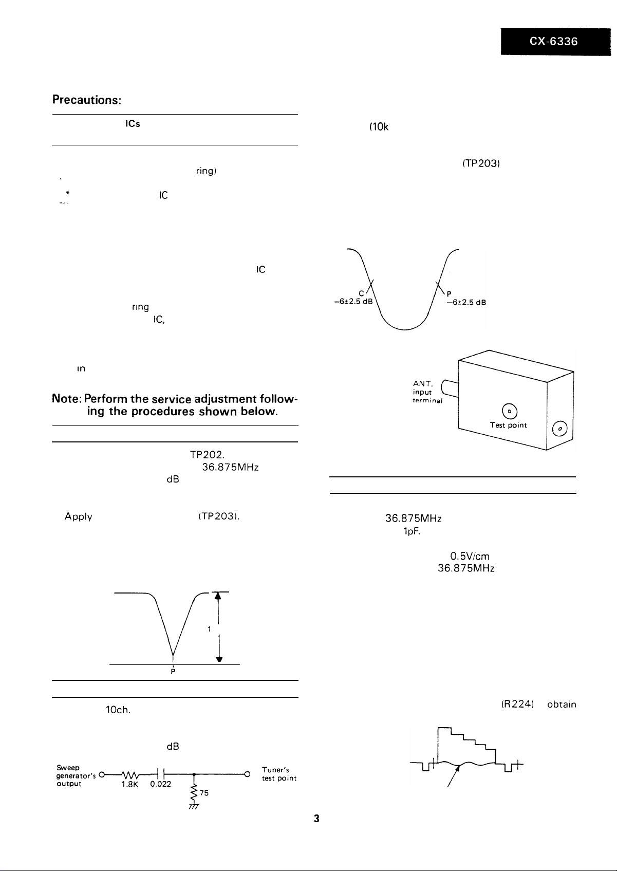
Precautions:
How to prevent
tricity
1. When replacing or handling the IC, be sure to put on
your wrist a metal ring (earth
-
to ground.
*
Avoid touching the IC directly by hand as much as
--_
possible.
2. For the soldering iron and other jigs in use, be sure to
connect them to ground so that their potential is the
same as that of the PWB and/or IC.
3. The PWB cannot be connected to ground in some condition although you attempt to attach the rC to that
PWB. In this case, be sure to keep the PWB at the same
potential as ground by touching it by your hand on
which a metal nng is put.
4. When handling the
wear such clothes as not causing static electricity; the
ones of wool, silk or synthetic fiber should be avoided. This is Important in particular when handling the
IC In a dry environment.
ICs
from damages due to static elec-
ring1
that is connected
IC,
it is recommended for you to
__
3.
Connect the response lead to TP207.
4.
Connect a resistor of 100 ohms to both ends of
R235 (10k ohms).
Note: Keep the lead of the 100 ohm resistor as
short as possible.
5.
Apply AGC voltage to AGC
voltage so that the waveform on oscilloscope is 1
VP-P.
6.
Make sure that the overall waveform is as shown
in the figure below. If not, adjust it with the aid of
IF transformer of the tuner.
(TP203)
and adjust AGC
Note:
P-detector coil adjustment: T201
2. Connect the response lead of oscilloscope to
3.
4. Adjust AGC voltage so that the waveform on oscil-
5. Adjust T201 so that the waveform peak on oscillo-
Perform
ing
1. Connect sweep output to
l Sweep central frequency:
l Sweep output: 80
TP207.
Apply
AGC voltage to AGC
Note: The AGC voltage should not exceed 7V.
loscope becomes 1 Vp-p.
scope becomes aligned with P marker.
the service
adjustment
the procedures shown below.
TP202.
36.875MHz
dB
(TP203).
follow-
T
1
VP-P
T
i
Overall waveform
1. Receive
2. Connect sweep output to the tuner test point
through the specified jig.
l Sweep output: 70
loch.
signal.
dB
1
36.875 MHz
IF transformer
AFT adjustment: T202
1. Receive sequential colour bar signal.
2. Connect
capacitor of
3. Connect oscilloscope to TP207.
l Oscilloscope range:
4. Adjust the output of
the waveform beating on oscilloscope be observable.
5. Adjust the tuning control so that the waveform on
oscilloscope is free from beating.
l Set the band switch at VHF position and adjust
the tuning control.
6. Set the band switch at normal position and adjust
TP202 so that the waveform on oscilloscope is free
from beating.
l Turn on AFT switch.
Note: Set the RF AGC control
36.875MHz
1pF.
normal picture.
oscillator to TP202 across a
36.875MHz
0.5V/cm
AC
oscillator to have
(R224)
to
obtain
gztor’s e-4hk-+
output
,.8K &-g-o
~redds”t
Adjust for zero-beating.
3
Page 4

RF AGC cut-in adjustment: R224
1. Receive 10 ch. signal.
2. Set the signal input level at 52 + 1
dB.
3. Connect CR oscillator to TP204 across a capacitor
of lOpF/16V: This capacitor is to cut off DC supply.
l Oscillation frequency:
l Output voltage: 0.1 Vp-p (Output
1kHz
sine wave.
voltage availa-
ble at TP204)
4. Adjust R224 so that 1 kHz signal disappears from
TV screen.
5. Set the signal input level at 52 + 3 dB and check
that 1 kHz signal appears on TV screen.
If
1 kHz signal does not appear, set the input signal level at 52 dB again and follow the procedure
in step 4 again.
Sub-brightness adjustment: R421
1. Turn S501 on by tipping it rightwards in order to let
the raster be linear.
2. Set each control as follows:
l Screen control: at MIN position
l Sub-brightness control (R421): at MIN position
l R-bias control
l G-bias control
l B-bias control
l G-drive control
l B-drive control
l Contrast control: at MIN position
l Brightness control: at CENTER position
l Picture tone control: at CENTER position
l Colour control: at MIN position
(R862)
(R863)
(R864)
(R857-A)
(R857-B)
3. Receive lion head pattern signal.
4. Connect oscilloscope to TP850.
5. Adjust R421 so that the waveform on oscilloscope
is at 15 Vp-p.
12. Adjust each drive control for good white balance.
l Colour temperature:
7300OK
x=0.303
(
Y=O.310
)
13. Adjust brightness control and contrast control to
obtain a dark picture. If the white balance is disturbed, adjust the bias control to obtain good
white balance.
14. Again brighten the picture and adjust each drive
control for good white balance as in step 12 above.
Carrier wave-phase adjustment: R826
1. Receive sequential colour bar
signal.
2. Connect oscilloscope to K4 terminal (blue) and adjust synchronism of oscilloscope to obtain the
waveform as shown in the figure below.
minimum
3. Adjust the phase control so that the
l-l
part@of
B-Y
output waveform becomes minimum as shown in
the figure above.
Sub-colour adiustment: R817
1. Receive sequential colour bar signal.
2. Set each control as follows:
l Contrast control: at MAX position
l Brightness control: at CENTER position
l Colour control: at CENTER position
l Picture-tone control: at CENTER position
3. Connect oscilloscope to TP850.
4. Adjust R817 so that the white output (75%) and
red output will have the same level.
Background adjustment: Screen control R862 R863
R864
R857-A/B
6. Remove oscilloscope from TP850.
7. Adjust the screen control so that raster of red,
green, or blue appears dimly on screen.
8. Adjust the bias controls except for dimly appearing colour to let the picture on screen be white.
9. Adjust the screen control to obtain cut-off point
of CRT.
10. Turn S501 off by bringing it back to the center in
order to resume the normal raster.
11. Set the contrast control at MAX position.
Horizontal Size adjustment:
1.
Receive lion head pattern signal.
2. If the horizontal size is at less than 7% of
ning, insert the socket into the opening (2).
Vertical size adjustment: R525
3. Adjust R634 to have proper horizontal center.
4
overscan-
Page 5

Vertical linearity adjustment:
R520
-
Protector check
1. Receive lion head pattern signal.
2. Adjust R520 to obtain good vertical linearity.
Vertical
size
adjustment:
R525
,* .I --
3. Adjust R525 to have 10% of the vertical overscan.
Vertical center adjustment:
S502
--
1. If the vertical center of picture is 3mm higher than
the center of CRT, set
it is 3mm lower than the center of CRT, set
S502
at “down” position. If
S502
at “up” position.
1. Apply
.that
DC25V
to D605 (cathode side), and check
the protector remains inoperative.
2. Apply DC 30V to D605 (cathode side), and check
__ _
.
that the protector gets operative.
3.-Connect
a resistor
(10k
ohms) between base of
Q603 and ground, and check that the protector
gets operative.
-
-
5
Page 6

_-
Checked Circuits
l Power Regulator Circuit
0
Horizontal Deflection Circuit
l Picture tube Bios Circuit
l Video Circuit
0 Picture tube
TROUBLE SHOOTING
r
When the power switch is push on,
is there caused a raster?
t
TABLE
: -! - _- : ..:- -__ I__ \
.
No
Are the Fuse
blown?
I
No
(F7001)
Yes
t
v
Replace the tuse
with new one
_ _.
Yes
_.
.- ^
t
,
Norma I
c
The tuse is ogain
.
blown out
Abnorma I
r-----
----1
Checked Circuits
l Horizontal Output Circuit
Check
R640 and Horizontal
Drive Circuit
I L606
L------------A
Q601, T601,
I
Normal
and R636
L---------a
.
NO HRIZONTAL SCANNING
Abnorma I
1
I------- -----
I
Check
1
R640 and- Horizontal
I Drive Circuit
L------------d
t
t
(2601, T601,
a------m--d
1
l
1
I
I
A bnormo I
l
OSC . Circuit
L----------d
w--m-
1
I
I
6
Page 7
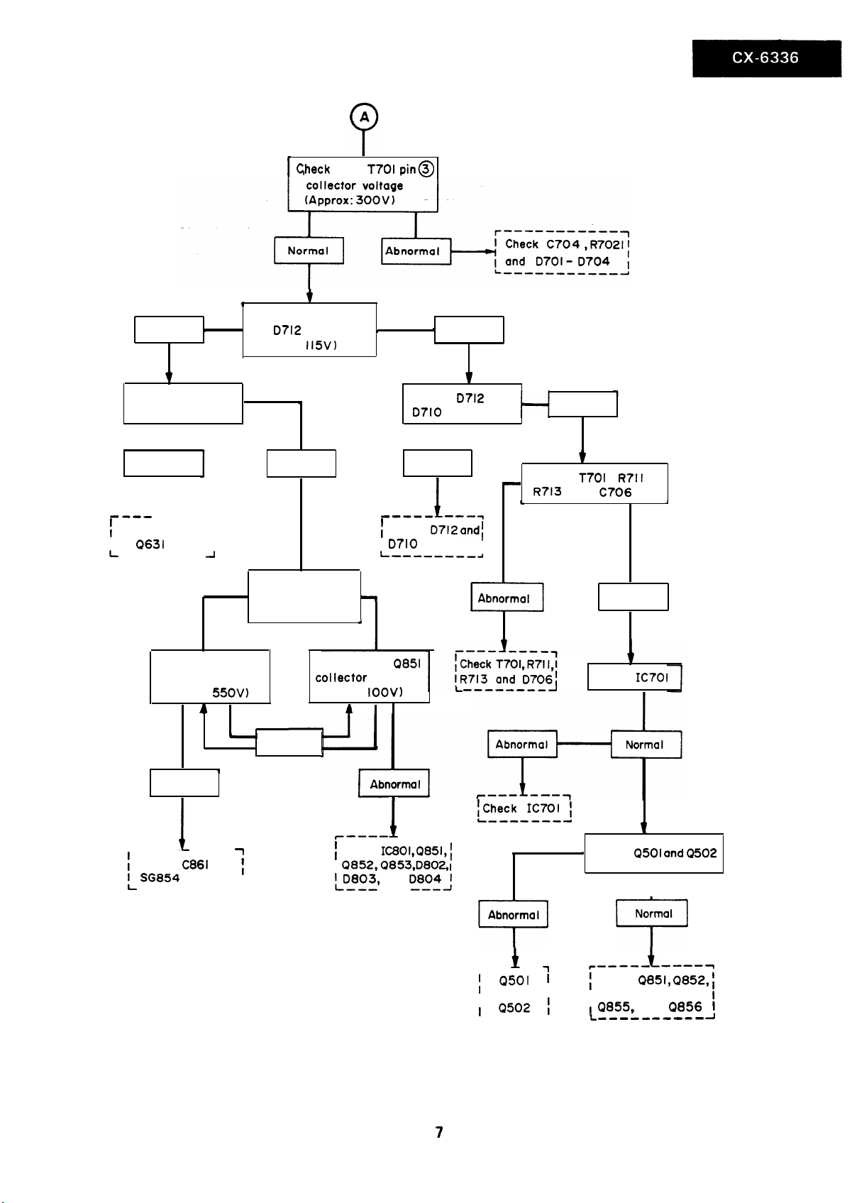
[ C,heck
for
T70l pin@)
Normal
1
Check for the CRT ,
heater vol toge
I
Abnormal
w--e
I
I
L
1
a----
Check
0631
--B-m---
Check for the
screen voltage
(Approx:
Abnormal
.
1
J
A
Normal
,
Check for the voltage
of
0712
(Approx:
,
I
I
Check for the Bias
circuit of picture
tube
55OV)
I
,
Norma I
t
cathode
ll5V)
/
*
Check for the
COI lector
(Approx: IOOV)
1
1
1
--e-e
Check 0712
I
I
D7lO
L
.
-
4
voltage Check
Check
0710
Abnorma I
--------a
Q85l
’
Abnormal
1
D712
I
L
m--y
andl
--------A
and
I
-
Check
c
Norma I
t
T70l
R713 and
,
C706
R7ll
I
Normal
1
IC7Ol
----- ----
I
Check
L SG854
I
C861
and
---------A
!Check IC701 1
L-------d
r-e--
1
1
I
i
Check IC8Ol,Q851,~
I
0852,0853,D802,l
lLD803,
I
-----
and
---------
D804J
.
Abnorma I
1
Check
7
i
-- --
r
; Q50l 1
I Q502 1
------a
1
----am-
i
Check
Q853,
Q855,
I
I
L
1
0501 und Q502
I
Normal
LT-’
t
-e-e-)
0851, Q852, i
0854,
and
----------
0856
.
1
A
7
Page 8

Checked Circuits
STF Amplifier Circuit
Sound Detector Circuit
Audio
Output
Circu 1
t
.
NO SOUND
1
,
1
Check
L301, C3lO
f
CF3OI
Check for the
Norma I
t
When the sound control
is set at MAX, does noise
increase
3
I
1
No, or very small
I
f.----- -a----,
C306, C307, f
and
i
Check
I
C317, R3lO,IC202
I
I and
L
-----------A
I
t
_I
C314,C315,
iC3Ot
pin@of
1
I
j
,
I
TC30l
(l2V)
1
Check
L703, 0714, t
1 C733) C735)
I and R730
-L
-------a---
c734,
f
I
J
Checked Circuits
0 Vertical Output Circuit
Check
and bias control
circuit.
- _
r-----
0501,
-----
1
NO VERTICAL SCANNING
Waveform at Collector
of
Q503
is normal
,
Q502
-
1
?
Abnormo I
_
. .
. .
- -
.-
Page 9

Checked Circuits
l P-IF Circuit
l AGC Circuit
l Tuner Circuit
l
tB
Supply Circuit
IN0
PICTURE, NO SOUND
1
Norma I Abnormal
t
When band switch is
changed, does VT change?
Check tuner,
AGC and bias
control circuits
,
yet the reception is
Check for tuner
BU, BH, BL and B
(about
IZV)
I
I
Check for
f
l
Band Selector Circuit.
L-,------,--,,A
I
IC201,
and yet only the sound
changes remarkably.
b
%~?~~~~~~~~~
voltage at
pln@of IC202
Normal
i-’
I
I
1
Check IC201,l
;
T201,
l L2ll,L2lO, l
I and
CF202
I-
----e-
R233,;
I
J
the
IS
l2V
Abnormal
7
t
Normal
r
I Check tuner,
L2!rE!!t-~~--
----
. .
J
-- ----
bheck
CF2Ol
c--e-- ------
Check R220, R217,
i
I
1 R218
L---,-----,,d
t
l
and C235 I
1
I
Page 10

-
Checked Circuits
- 0
CHROMA Circuit
l VIDEO Circuit
r
NO COLOUR
I
Waveform at pin
5 of
IC801
0
normal ?
Waveform at
emi
tier (TP207)
of Q401 is
normal ?
is
Yes
I
I
Yes
No
1
Each termina I
voltage of tuner No
is nomal ?
(+B,BL,BH, BU)
Yes
Check XC20
and band
selector circuit.
I
I
Yes
Check Tuner and
control circuits.
10
Page 11

CHASSIS LAYOUT
CONTROL
UNIT
DUNTK4726WE
S?OOl
POWER SWITCH
POWER
SWITCH
DUNTK4727WE
SP301
SPEAKER
C
UNIT
I
!
j
REMOTE CONTROL
DUNTK4728WE
UNIT
CRT
SOCKET
UNIT
DUNTK4544WE
17
_-_
Xl?901
Itsol
-n
CF601
0
E202
TP205
u
SUB BRIGHT
TP207 0
0201
IC201
0401
0
R42la
IRG)
TP203
0
0
CF201
TP202
0203
0
TUNER
0
0
rl
C&O2
TP204
l
0202
00
R224
F
RF AGC
0
SCR601
ICJOI
1
LJ
TBOI
cl
(IT)
U
LeoI
Ll
0402
0801
l
l
1
======I
L
R826
Q603 u
a
rl
CS!zl
R525
V-SIZE
El
0604
R520
V-LINE
I
@iI
I
IK)
0
0503
0501
II
’
a
V-SENT
R508
so2
u
R629
0
0
R630
0 CL41
0
(HI
C728
DUNTK4543WE
1
I
2
I
3
I
4
I
s
I
6
11
Page 12

RB62 R-BIAS
RB63 G -BIAS
0853
a.
TPBSI
mm51
--
0854
.*
.-- -
RB57-B B-DRIVE
I
.LK)
<
- ._.
._
TA)
F700 I
T2A
tAB)
AAI
0
ICI03
a
ICI02
r-l
LJ
‘7
AA2
0
~
ICI01
L7001
(RG)
-
0105.
3i
(l-B)
0101
l
Cl01
R7001
/
a0102
1
/
I I
01007
(TA)
I
(TB)
n
u
ICI-I
SlOO5
0
cl
l-l
u
(Ml
0104
0
Al A3
0 0
51008
4CH 0
cl
SIOI
I
7CH
0
cl
-‘:“,‘,,
q q q q TU”E q
SlOO2
(-) (+I (-) (+)
SlOl5
L
/------p
5CH
8CH
SIOOI
R400l
2CH
S1006
q
SlOO9
q
s1012
cl
SlOO4
R300l
I
0
0
0
SlOO3
PICTURE
3CH
s1007
0
cl
SIOIO
6CH
0
q
SlOl3
9CH
0
cl
COLOR
I
CONT
1
f
BRIGHT
s-VOL
DUNTK4726WE 1
I
7
I
8
1
9
I
10
I
11
I
12
I
12
Page 13

PRINTED WIRING BOARD ASSEMBLIES
(All the
PWBs
h
ere are shown an viewed from their wiring sides.}
ec: g
=P
u
-t
x2--?
1
N
Y
yi
D-m%
070.
ii &
a
‘$‘W -
: “Z
u;;:,
S‘ g< _~ e%.._ -
1711
pF-&
-fp-.
I
3‘
SC
I
9738
-*r=f
c ra
+ I
,.~ .
2
I
i )
/
/
’
/
LTB
zi
c
_I
i
I
:
&I
t7.m
.
+
A_
65
C73‘
l
l
ih
t735..
, --.-..-
I
5
I
6
I
Mother
3
Unit
J
R 19 xi_,
B
.I;=; p’
1 5 y!;;:y:
J-4
r---:
4 f.
-----
:
t9
4
e 0711-.
* ik
i733
13
Page 14

CRT Socket Unit
57001
f! st
r-1
El
I
E&g e SW 5 B
89
2
Lt
:a;
pk 5
i
=Y
- Cl004
=u
9
El-
8
+~(-J0’oo7
...)
__ 5
3C”
s
1007
cl
9cH
SIC13
“0:
0
P
p
lOCH
51014
cl
16
- ,,“,a
“.
-
I
.‘
,s
-
0
1.
Power
Switch
Unit
Controi Unit
Channel Select
Unit
Page 15

DUNTK4543WE
(OPWBF4543CE)
BLOCK
DIAGRAI
TO
DUNTK
4547WE
(RG)
BAND-SELECTOR
d ICZOI
IX0260CE
I
RG)
AFT.-DRIVE AFT-SWITCH
- 0201
2SClBl5tGR) 2SK304
-
0202
-
t
!I
&--Qgyy-~-
) INVERTER 11 FILC0020CE 1
IBCE
FILTER
I
t ,
r
LIMITER
I
1
VIDEO DET
COIL
T201
CILDOI
SIF CF301
FILC0007CE
s
TUNER
VTUMF4EA-702/
PIF. AMP
1
1
I
SAW-FILTER
FILCOO94CE
R224
RF-AGC
I
+
-
RCILZO55lCE
F
115v
il
AUDIO -
ATT
IC202
IX0388CE
SPEAKER
r
AC240V
5oHz
1
1
I
2
SOUND OUTPUT
IC301
IX0365CE
RECnFIER
D701- 0704
DX0240CE
I
3
RECTIFIER
’ D714
DX0220CE
CHOPPER-TRANS
*
T7Ol
TRNZ0235CE
t
1
4
RECTIFIER
D710
DX0246CE
I
5
I
6
I
e
I
15
Page 16

ZK
DIAGRAM
ZiMP. I::o:,.
0652
2SA1015(Y)
H DELAY
UNIT
L801
9CILZ0551CE
AUTO
MATIC
COLOUR NOISE
/---
- SEP.
NTSC/
SWITCH
I
_ 2nd
AMP.
TO
PAL
CHROMA
DUNTK4726WE
t
i (IT) 1
T
I
-
(IT)
1
O(O) ]
I
4.43MHz
osc.
b
I
l--fKl--
P
DUNTK4544WE
(OPWBF4544CE)
- 0854
41
-
I
t--
‘-
-
-t-
g+l
R-OUTPUT
2SC3417
R-DRIVE
08.51
r
G-OUTPUT
0855
2SC3417
G-DRIVE
0852
2SCl815tGR)
I I -
R857 1 R863
G-DRIVE
/
H.V
9,
I I
f I I
I I
’ ’ !
CRT
Lt
f
;
V801
, I
I 1
t
t
1
G-BIAS
I
-II
I
Y--i-
J
DXOIOSTA
?J REGULATOR
0609
2SD313
I
la--J&J
2nd
VIDEO AMR
-1
r-l
I
I
L
--3
I
32tH OSC.
CF6Ol
FILAOO07CE
4
I-
I
J
I
H-DRIVE 2SA958iY)
0601
T60 I
TRNZ0193CE
HOR. OUTPUT
L
-III:
VERT DRIVE
0503
2SCl514
-
-.
L
VERT.-OUTPUT
Q501
2SC2168tY)
0502
,
tI-/L--,1
-
RS25
V-SIZE
R520
V-LINE.
s502
V-SENT.
VERT.
HOR.
TO
DUNTK4543WE
Di)(F.B.T.)(L4)
I
&
1-
(F)
:1x
1b.Y)
6
I
7
I
8
I
9
1
10
I
11
I
12
J
16
Page 17

TO
DUN’
A
DUNTK4726WE
T
AFT
c
KEY
MICRO
QIOL
2sc
VT-
ICI(
1x0
FT
t-1
TUN
(+I
TUN
t-1
Ich
2ch
5ch
6ch
7ch
+-I
0
r
V N U
0
r
l (TA)
L
1
8ch
9ch
loch
n I
(TB) r
1
(TB)
r-
KEY
I
I
I
i-
0 0
L
F
ninn7
“I”“,
11(
I
f-
DVAICAPC
rfivfu7bc ; +
R3nnl
F
t I
l
!!) l
1
0 II
1
1
,
R4001
e--w---
[ L.;
CO/NT
I
I
BdIGHT f
I
P--TONE
i
LB-,_-+
A
f
(IT)
I
TO
DUNTK4543WE
i
-
v
ADG COIL
I
v
-_
H
_ +“s- .-- .
: TO
+
DyNTK4543WE
__-
-
_:-
.
.*_
: -.
--
.
1
I
2
I
3
17
I
4
I
5
I
6
1
Page 18

_ _-
;:NTK4543WE
AFT
1
VT-AMP
KEY
IClOl
IX0605CE
MICRO PROCESSOR
VT
_
1
1
_.
@SClSlS (GWI
I
(2105
S - MUTE
J
-1
DUNTK4728WE.
I 1
TO
DUNTK4543WE
KEY
__
_
RESET
(A)
I.
TO
DUNTK4543WE
LINE - FILTER
A
AC240V
50Hz
(A81
DUNTK4727WE
I
7
I
8
I
9
I
18
10
=
--
I
11
1
12
__
z<_--
1
Page 19

B
C
DLNTK4544WE
D
lOPWBF4544CEZZl
7
- c321
+
116W
‘Urn
/ P
I I
IC3D
I
r
lX0365CE EdUW-AMP1
-OO(L2~K&3
E
.F
0
,WMTES
(K)
VxIIXEi 1 r
:Y,”
I 3mA
Ifocvm IKE
, ix1 +-I”.
I i f
1 I I
III ?
I f 1
t i 1
~VeDl
* : ;““““*
It
1;: ;
111 i
::: :
,a, --I
~
-.-A -
a:
_______-----___------------------------~---
~XTD’ IXOTJIQ tPDWEi?-RE6tUTORJ
CT39
I%02
it-
19
Page 20

SERVICE PRECAUTION:
-
-
-
The area enclosed by this line
connected with AC Mains Voltage.
(
When servicing the
area, connect an isolating transformer between TV receiver
and AC line to eliminate hazard of electric shock.
) is directly
DLNTK4543WE
R4411)
7
10 /
& h
s4 I :q &n7
&4,
I, /
4-l
!
-----_-_----
=WfER-ftE!3JL4TOFIP~
c73a -
I,% 2
c,,s Kzoo.?.cE
~:~
_-___ -----J
I
IZO 057cE
4
F870P
rCOI0 E
*- OEZ I
-cE>
1-1
C716
0015
RIVI
1
rl
7
I
8
I
9
I
10
1
11
I
12
I
20
Page 21

(BLACK)
cPr,mn
Th,
WC”ll
dloptwn I*
Lltermce
from
All !he
“Olh?~sr I”
All
mere ‘lpuror repr**on,
OI COloUr
NOlO
,
sqnolr
Ftsmrtor
1 I)
Restrl~“ce
121
All
IO,I,,W,
13)
AU
re,tstw,
: g--p @--csmenr
11)
corJocmnce
(21
All
cwoc~!ws
(31
AH
WLl--Uykv
aode
Doat
are shorn n ~01,s nmne
0th~
woe
CBLI - -Blue
(BR)
--B,orn
orlglm\ one tbeMIClorC
your.
coch
~om,we meo,u,ed wrh
WE
Y- we
dm.n n oh,,
Of0
I/6 t”OlI. UMs, otllarrne “Ned
ln4e.l orher*aa n0t.d.
or* CWQon.
@--Oxat Fen @--SIWY @--Uetot
d~~,orn n UF=IO-‘Fdwrwt,e mma P=“LIF=,O-‘~ F
“DMS
ore
ore 5OV.
LPFI--
lR1
--Red
uh,s otbrms noted
Polypro
COlhoda cot4”r
CY’)- - 1~101
IOR)--Dronpe
COPOC~~M OTC CWML. ,,a,,
OTC dworn n
tBKb--BUXk
F,m
mere
,000 MI
D~WW~~ ~T)IW
(TA)--- T~nloh,m
,WB--Wh,*
d,$arol ,,,,,I, ,,,c,o,
“Olt~pe Iaveh meoued
: K=
moy be 0
UPon receFdan
,.OOO.OOD
tG,--G,**”
n,gtl,
Coornp
R122
IS<
“‘w’
I-
L
C,,,.
IWP.
i
7
r-
I
I
,
p@
e-g
213
1.
:z is? *
::I
80
co5
RI3
R,,,
seuemcMKbdl(
I
I
I
113
RI19
(BLIIEI e
0
-_--.
.
z
lib
RB.3 Rl.8
:o”,
:I%,
m,..? RI.0
:z-al I :,%#,
I-i’
OlO5
2SC1Bl%GRl
b
1130
&
IoN
f
I
0
.301
1
E
I:
v
11
tV303
‘UN ‘.l
:r
K-y ,
‘4
a0 ; =
nL; \
y-$ 3
111
jiDm&r !
8)
I
I
I
/
;“;q-@+
,
! :
7
1
I
1 ~D~05~odiDi07kDIW “’ / / j
IrI
I
/
I
1
r
CXoo..T. x4
IXO605CE
ICIOI
RIO5
GZH-SELECTOR)
j
*
I
I
,st~)y
t
II
‘R
----
3cH
*y-Ii;
B
c
j
4
& /
! I
IDI-.
0
1
0
2
0
fitf
a
-GJ-pJ
0
&)I
I
4
^
^
a
& BI
F
I
I
- 0 6
E
I
I I
x-l
“I /
OIW~-D1cm6
1SSIIsiw
1(100.?
6 CI
t
cDE 7
I
r I,
P
L
_I -1
// :9
/
/1r707-
’
IllI/
X6
$1
RmcM
R1003
R1Ms
Rmcm
’ III
WIT
A
_-------_
Ft,o
i
I
No645cEI
3T~mEDl
-1
51007
5,006
-
5mos
SW
51010
-
5,017
‘CM
51012
w
StOl.
‘0%
D1007
PXO!WCE
I
I
I I.
~
/
i
r----i
-_-__d
9lh’
, I&
a:‘oi.
~~~~~Zi~l
III
RID6
Q-
m D
j-y-++/Gj j 1 1 ~I+q
. .
I L
wy-i>,
M,,
-YG%F3+1-1
..
-3-l
/ “’ ?i&b43BS-,
; / +-+-y-F*;
i.l I
* g9-
iI !\ 0 coo
-0
I
!
%
u
’
:
1-j
p::,
1
z
::!?
q
ill I
/
ff-y-q&Yh
(
I
I.
7
h
Ezi
-I
i,i’rpy]/
j2*p!
lKz
’
T-
0
m
<a
b-1
I D!??-- 1
) 1
‘,yy 1 j
I /
I II J j 1 /
I l4-wi IA’ ’ I WI
,2:&&i A/ / AT+
EXooslGE
I
ICI02
IXO439CE
IMEMDRY~
dllE~ml~l~ /
DWTK472BWE
tOFWSF472BCEZZl
A
j
I
&r
iI
ji \
.Y3V
CICImf
a-
ll
I
Izv
UT,
I
I
iI/
I
li
:
21
lNO304cT)
DWTK4727WE
lDPWBF4727CEZf~
Page 22

DESCRIPTION OF SCHEMATIC DIAGRAM AND WAVEFORMS
PARTS
MARKED
MAINTAINING THE SAFEN
PLACE THESE PARTS WITH SPECIFIED ONES
ING
THE
SAFETY
CAUTION:
This
circuit diagram is original
slight difference from
All the voltages
meter.
All
these figures represent
reception of colour signals.
Waveform Measurement Conditions
1.
Upon receiving
2. m indicates wave form
and measured from point indicated to
WITH *A
AND
in each
EBU
- (
OF THE
PERFORMANCE OF THE
yours.
point
are
the
colour bar signal of
check
) ARE IMPORTANT FOR
SET.
one,
therefore there may
measured
voltage
points
chassis
BE SURE TO
FOR MAINTAIN-
SET.
be
wrth
digital multi
levels measured upon
70 dS in
(See
field intensity.
chart, waveforms
ground).
RE-
NOTE:
RESISTOR
11)
Resistance values are
K=
1,000 M=
(21
All resistores
(31
All resistores
@ . . . . . .
@ . . . . . .
a
@. . . . .
CAPACITOR
Capacitance
(1)
p=uuF=
(21
All capacitors
All capacitore
(31
/MU . . . . . .
(TA). . . . . .
DIODE
Diode
are,
colour.
(BL) . . . . . .
(Yl. . . . .
(G). . . . .
I,i?OO,OOO
are
are Carbon,
Solid
Oxide
Film
.
Metal Coating
values are
10-12F
are
are Ceramic,
Mylar
.
Tantalum
shown
parts
BLUE
.
YELLOW
.
GREEN
shown
in
ohms:
l/8 watt, unless otherwise noted.
unless other wise noted.
. . . . . .
Cement
8
@ . . . . . .
Special
shown
in u=
10e6F otherwise noted
5OV, unless otherwise
unless otherwise noted.
IPf) . . . . . . . Polypro
name other Diode
(BR) . . . . . .
(WI . . . . . .
(ORI. . . . .
Film
BUCK
WHITE
.
ORANGE
noted.
are
shown cathode
@ 48OVPp
(1OOV
@ l.GVp-p
(0.2V
@ 4.8Vp-p
(2V
20psec)
10usec)
20psec)
@
8.OVp-p
(2V1
@
B.OVp-p
(0.W 20wec)
@! 1.14vpp
(0.2V
@ 1.4vp-p
Ousec)
20ysec) (0.1 V 1
(0.2V 20rrsec)
@ 4.ovp-p
(0.5V
@ O.GVp-p
2OjSec)
Ol.rsec)
11 9.2vpp
i0
(2V 20psec)
/
@ 96Vp-p
(2OV
5msec)
@ 2.ovp-p
10.2V 20usec) (0.1 V20ctsec)
@ 12ovp-p
(2OV
2Opsec)
@ toovp-p
(2OV
5msec)
@ 0.84Vp-p
@ 114vp-p
(2OV
@ 152vp-p
(2OV 1
20psec)
Opsec)
@ 0.7vp-p
(0.1
v
@ 112vp-p
(2OV 20ysec)
2Owx)
7
22
Page 23

TUNER
A
VTUMF4EA-7021
F
I
t
1
c
R
I
{\
:!
1
VS2SD313F//lE
VS2SC2168Y12E
,
LEYITTER
L--‘LLECTW
VS2SClBISGW-I
VS2SCl906NlE
VSZSA950~
RH-IX0439CEZZ
RI-I-IX0412CEZZ
VSZSDl556//2E
SOLID STATE DEVICE BASE DIAGRAM
VS2SC1514-
VS2SC2271-EIA
RH
- PXOI49CEZZ
I-
-EMITTER
COLLECTOR
RMPTE0043CEZZ
/ZE
RMPTCOl50CEZZ
8
7i-7
RH
-1X0260CEZZ
I
c
ii
RH-
IX0731CEZZ
YP
h
t345
RH
- !XC703CEZZ
%y+
L i : _ L
23.5
5
VS2SK304CO/- I
VHSSF3H42// - I
-GATE
RH- IX0368CEZZ
30
nnnnnnnnnn
RH- IXO767CEZZ
6
-..
_ - _-
16
I
I
-
-
-
-
-
:
CIITHOGE
Rr-IX0249CEZZ
ANODE
4z3.5 GI G9IO0,z0
23
c
(
c
L
L
4,
-
Page 24

PARTS LIST
PARTS REPLACEMENT
Replacement parts which have these special safety characteristics
identified in this manual; electrical components having such
tures are identified by A in the Replacement Parts Lists.
The use of a substitute replacement part which
same safety characteristics as the factory recommended replacement parts shown in this service manual may create shock, fire or
other hazards.
“HOW TO ORDER REPLACEMENT PARTS”
To have your order filled promptly and correctly, please furnish the
following informations.
1. MODEL NUMBER
3. PART NO. 4. DESCRIPTION
NOTE: THE PARTS HERE SHOWN ARE SUPPLIED AS
AN ASSEMBLY BUT NOT IN DEPENDENTLY.
b
VTUMF4EA- 7021
INTEGRATED CIRCUITS
IC201
IC202
IC301
,IC701
lcaol
RH- i
RH- i
RH- i
RH- i
RH- i
X0260CEZZ
X03aaCEZZ
X0365CEZZ
X0731CEZZ
X0787CEZZ
2. REF. NO.
VHFUHF Tuner
doeqnot
have the
Ref. No.
Q402
0501
0502
0503
0601
fea-
Q602
0604
BSCR601 VHSSF3H42/ / -
0201,
VS2SA950dl
VS2SC2 16BY/
VS2SA95BYl
VS2SCI 514VS2SC2271VS2SDI 556/ /
VS2SD313Fi
VHDlSSllSII-
401,
402.
404
I
406,
503,
504,
506
I
508,
602,
606,
611
I
613,
651,
652,
705
D202 RH-
BF
AF
AQ
AK
AT
AT
D502,
A
608,
D603,
80605
D609
AD610
80701
A
704
.
0707
0710
D712
D802
XR801
604
804
RH601,
607,
706,
714
RH-
RH-
RH-
RH-
RH-
I
RH-
RH-
RHRH-
I
RCRSB003 1 CEZZ Crystal
Part No.
I - 1
/ 1 E
/ 2E
/ 1 E
2SA950
2E
2SC216B(Y)
2SA95B(Y)
2SC1514
ElA 2SC2271
2E
2SDI556
2SD313(F)
1
SF3H42
DIODES
1 AB
EX0056GEZZ
DX0220CEZZ
EXOI
39GEZZ Zener Diode
EX0034CEZZ
DX0105TAZZ
EXOI
69GEZZ Zener Diode
DX0240CEZZ
EX0060GEZZ
DX0246CEZZ
EXOl
52CEZZ Zener Diode .
EX0072GEZZ
Zener Diode
Zener Diode
Zener Diode
Zener Diode
PACKAGED CIRCUIT
Description Code
AD
AF
AC
AE
AC
AP
AE
AG
AB
AB
AA
AC
AD
AA
AB
AA
AD
AE
AA
AK
TRANSISTORS
0201,
Q202
Q203
0401,
>
603,
vs2scla15GW-
801
VS2SK304CDi
VS2SC1906ii
VS2SAlOl 5Yi
652 L211
1
2SClB15IGR)
- 1 2SK 304 AC
IE
2SC 1906 AC
1 E
2SAl015(Y)
A0
AC
24
L204,
206
L205,
609
L209
L210
VP- DF
VP-
VP-
VP- XF
VP-
lR2MOOOO l.2pH
DF6BOKOOOO
CF6BOKOOOO
120KOOOO
XF4R7KOOOO 4.7pH
COILS
6BpH
6BpH
12pH
AB
A%
AB
AB
AB
Page 25

t?ef.No.
Part No.
Description
Code Ref. No.
Part No.
Description
Code
L301
L302,
303
L403
L404
1L602 VP- L K l~OOKOOOO 10pH
1L603, VP- MK 1 OOKOOOO
I
608
L604
L605
L606
L607
L610
L701
L702
L703
L801
L802
VP- XF
VP- CF
VP - DF R
RCi LZ0488CEZZ
RCi LP0097CEZZ
RCi
RCi
VP- CF
VP-
VP-
RCi
VP- CF
RCi LZ0551CEZZ IH-DL
VP- DF
180KOOOO
2R2MOOOO 2.2pH
39MOOOO
LP0070CEZZ
LZ0422CEZZ
390KOOOO
XF2R7MOOOO
CFR33MOOOO 0.33pH
LP0069TAZZ
3R3KOOOO 3.3/~H
102KOOOO ImH
18pH AB
0.39rH
Video Delay AH
1OpH
3gpH AB 727
2.7~H
47pH
Unit
CERAMIC FILTERS
CF201
CF202
CF301
CF302
CF601’
RF i L
COO94CEZZ
RFi LC0020CEZZ 5.5MHz
RF I
LC0007CEZZ
RFi LC0097CEZZ
RFi LA0007CEZZ
SAW Filter AK
SIF Filter
SIF Detector
32fH Osc.
Trap
TRANSFORMERS
T201
T202
T601
hT602
,T701
T801
RCi
LDOl 18CEZZ
RCi LD0099CEZZ
RTRNZOI
RTRNF
RTRNZ0235CEZZ
RCi
93CEZZ Horizontal Drive
1625CEZZ Flyback
LVOl
39CEZZ Band Pass Trans. AE
P-DET
AFT
Trans.
Regulator Trans.
CONTROLS
R224
R421
R520
R525
R634
R817,
826 Carrier Wave-
RVR-
B51
RVR- B 5
RVR-
B51
RVR-
851
RVRRVR-
B51
37CEZZ 5k(B) RF-AGC AB
139CEZZ
34CEZZ
31CEZZ
B5141CEZZ
38CEZZ
20k(B)
lk(B)
200k(B)
50k(B) Horizontal-Center AD
IOk
Sub-Brightness AB
Vertical-Line AD
Vertical-Size
Sub Colour
Phase
CAPACITORS
c222
c303
c317,
617
C318
c319
C321
c409
c503
c507
C512
c513
c515
C516
VCSATAlVEl05K
RC-
EZOI
30CEZZ 330
VCEAGAI
VCEAGAl
RC-
VCEAGAlCW477M
VCFYSB2AB224K
VCCSPA2HL470K
-VCEAGA2CW336M
VCFYSB2EB104K
VCSATA 1 VE 684K 0.68 35V
VCEAGH2CW227M
VCFYSB2EB223K
CWl07M
EWI 07M 100 25V Electrolytic AD
EZ0077CEZZ
1 35v
16V
100 16V Electrolytic AB
470
470 16V
0.22 IOOV Mylar
33
0.1
220
0.022 250V
25V
47p
500V Ceramic AA
160V Electrolytic AD
250V Mylar AC
16OV
Tantalum AD
Electrolytic AC
Electrolytic AD
Electrolytic AC
Tantalum AC
Electrolytic
Mylar
C602
C604
AB
C615
AB
C616
C619
AB
C620,
AB
AE 725,
AD 733
AG
AB AC625,
AB 626
AF
AB
AE C631
AB C632
AE
AE
629,
634,
C622,
C627
C630
C633
AC701,
-A 702,
730,
739
AC704
AI= AC706,
AE
A 707
c709
c710
c711
C716
AD
C718,
AE
AG
BH
AT
AD
AB
726
C720
C724
C728 RCc729
C732
c734
C738
C811
R416
R425
AR506
R508
R511
R529,
640
R530
R605
R619
AR620
AR628,
A 730
R629,
AD
AH AR636
AC
630,
713
R631
R649
VCCSPA2HL470K
VCEAGAlCW337M
RC-
EZOl 11CEZZ
VCEAGAlAWl07M
VCKYPAZHB
VCKYPA2HB 102K
RC-
VCFPPD3CA682J
VCEAAH2EW226M
VCEAGAl EW337M
VCKYPA2HB271K
VCFPPD2DB434J
VCFYSB2GB393K
RC-
RCRC- KZ007 1 CEZZ
VCEAGAI
VCKYPA2HB272K
VCEAGAI
VCEAAA2EW475M
RC-
KZ0057CEZZ
RC-
VCKYPA2HB222K
RC-
VCKYPH3DB561K
RCRC-
VCEAGAlCW227M
101 K
KZOOI GCEZZ
KZ0029CEZZ
EZO169CEZZ
HW107M
EW227M
KZ0035CEZZ 220~
EZOO69CEZZ
EZ0107CEZZ
EZOl 12CEZZ
KZ0024CEZZ
RESISTORS
VRSVRS-
RR-
RRVRSRR-
VRSVRS-
VRS-
VRDRR-
RR-
VRN-
RR-
VRS-
PV3ABl02J
VV3AB681
XZ0091CEZZ
WZ0090CEZZ
VV3DB392J
WZ0065CEZZ 3.9k
VV3DB562J
VV3LB472J 4.7k
VV3DB 103J
RA2BE 103J
XZ0090CEZZ
WZ0082CEZZ
VV3AB2R7J
XZ0092CEZZ
VV3DB222J
47p
330 16V Electrolytic AC
1000
100
100~
0.001 500V Ceramic AA
0.01 Ceramic AC
0.0068
22
330
270~
0.43 200V Metalized AE
0.039 400V Mylar
0.01
330 4oov Electrolytic AT
0.0022
100
0.0027 500V Ceramic AA
220
4.7
0.0015 2kV Ceramic AD
0.0022 500V Ceramic AA
220
10
560~
330 25V
0.001 2kV Ceramic
220
lk
J 680
18
150
3.9k
5.6k
1
12
470
2.2k
500V Ceramic AA
6.3V
500V Ceramic AA
1.6kV
250V Electrolytic AD
25V Electrolytic AC
500V Ceramic AA
5ov Electrolytic AC
25V
250V Electrolytic AB
2kV Ceramic AB
16OV
2kV
1w
1W
1/2w
low
2W Oxide Film AA
5W Cement AD
2W Oxide Film AA
3W
10k 2W Oxtde Film AA
IOk
5w
2.7
1W
ll2W
2W Oxide Film AA
Electrolytic AC
Electrolytic AB
1ov
Metalized AE
Polyester
Polyester
Ceramic AC
Ceramic AC
Electrolytic AC
Electrolytrc
16OV
Electrolyttc
Ceramic
Electrolytic AC
Electrolytic AC
16V
Oxide Film AA
Oxide Film AA
Fuse
Resistor
Cement
Oxide Film AB
1/8W Carbon
1/2w
Fuse
Resistor
Cement AD
Metal AA
Coating
Fuse
Resistor
AC
AG
AF
AC
AC
AB
AC
AA
AB
AB
25
Page 26

ef.No.
Part No.
Description
Code Ref. No.
Part No. Description
Code
AR
703.
A
704
R
710
R
711 RR-
VRC-
VRS-
SV2HCl
WZ0099CEZZ
UA2HG825K 8.2M
OOJ 100 112w Oxide Film AA AC858
1 5w Cement AD AC861 RC-
1/2W Solid AA
SWITCHES
501 QSW- BOO1 5CEZZ Service AC
502
OS W -
B 0 0 2 0 C E Z Z Vertical Center AE
MISCELLANEOUS
B601,
8701
B703,
RBL N- 001 OCEZZ Ferrite Bead
602,
603,
702
RBLN- 0030CEZZ Ferrite Bead
RBL N- 0041 CEZZ Ferrite Bead
704, ASG854
705,
706
AC
AC A 853,
AB A 855
C864,
865
R865,
866,
867
ASG851,
A 852,
CAPACITORS
VCEAAH2EW226M
KZOO23CEZZ
VCKYPA2HB 102K
RESISTORS
VRS-
VV3DB123J
MISCELLANEOUS
QSoCV0814CEZZ
QSPGC0022CEZZ
QSPGC0020CEZZ
22
0.0047
0.001 500V Ceramrc AA
Spark Gap
Spark Gap
250
12k 2W Oxide Film * AA
CRTSocket
Electrolytrc AD
Ceramic
AD
AG
AC
AB
TRANSISTORS
1851,
!854,
852,
853
855,
856
VS2SC1815GW-
VS2SC3417;
1
2SC1815(GR)
IlE
2SC3417
DIODES
1852,
853,
855
VHDlSSllS!!-1
COILS
851 VP- CF 68 1 KOOOO
852 VP- XF 1 OOKOOOO 10pH
I
854
680rH
CONTROLS
857-A/
RVR-
B5083CEZZ 500k(B)x2
-B
862 RVR863,
864
B4567CEZZ
5k(B)
Green Drive/
Blue
Dnve
Red Bias
Green Bias
Blue Bias
AB
AC
01001
D1007
I
006
VHDISSI 19,
RH-
PXOl
64CEZZ Channel LED
)I - 1
CONTROLS
RVR-
AR3001
AR4001 RVR-
AB
AS1001
I
1014
AS101 5 QSW- BOO1 88CEZ Band Select
AB
Q4032CEZZ
G4013CEZZ
MISCELLANEOUS
RR MCUO 1 6 OC E Z Z
QSW-
K0030CEZZ
SWITCH
AS7001
AC
AC
QSW-
P0370CEZZ
Power Switch
INTEGRATED CIRCUITS
IClOl
ICI02
RH- II
RH- ii
X0605CEZZ
X0439CEZZ
lSS119
Remote Control Receiver
I
AB
AN
AF
AG
AR
AB
AD
AK
AS
AQ
26
Page 27

Ref .No.
IC103
IC104
DlOl,
102
D105 RH-
108
D104 RH-
;:1::::::‘:,;~
VHDlSSllSII-
I
R
MP T P 0 0 2 8 C E Z Z Positive Coefficient
Part No.
TRANSISTORS
DIODES
1 AB
EX0044TAZZ
EX0051GEZZ
RD8.2
PACKAGED CIRCUITS
I
ZenerDiode
Description
Code Ref. No.
AP
AE
F
AC
AB
AB
AB
AA
Part No.
C C AB A 5 1 6 6 C E S 0 Front Cabinet Ass’y
Not Available
GLEGP9007CEZZ
C WAK P 1 1 3 6 C E 3 7 Front Frame Ass’y
Not Avairable Front Frame
GDoRF 1572CESA
HBDGB
HBDGD301
Hi ND M 2 4 8 3 C E S A Indication Metal
Hi
Hi
HPNLCl
HPNLCOl GOCESA
CCABBl 650WEVl BackCabinetAss’y
JBTNJ BTN- 1354CESA Button, Channel
J KNBP
1058AF
GCESA
NDM2485CESA
NDP2379CESA
563CESA Indication Panel
Not Available
1321CESC
1099CESA
Leg
Door
SA Badge “SHARP”
Badge “LINYTRON”
Decoration Metal
Indication LED
Punching Plate
Button,Power
Knob
Description
Front Cabinet
Back Cabinet
Code
-
AC
BB
-
AL
AD
AE
AD
AF
AD
AW
AR
-
AC
AE
AC
LlOl
L102
L104,
105
L106
,L7001
Cl09
LC7001
c7003
iR7001
,F7001
VP-
MK560KOOOO
VP- XF 1 ROM0000
VP- XF
VP- XF
R
C i L F 0 0 9 0 C E Z Z
5R6KOOOO
120KOOOO 12/~H
56pH
1pH
5.6pH
Line Filter
CAPACITORS
RESISTOR
RR-
WZ0096CEZZ
6.8
low
Cement
MISCELLANEOUS
QFS-
C2022TAZZ
QF S H D 1 0 0 2 C E Z Z Fuse Holder (2 Used)
QACCL 5001CEZZ AC Cord
Fuse, T2A
AB
AB
AB
AB
AL
AB
AG
AD
AE
AE
AA
AP
SP301
AP
27
Page 28

SHARP
T5652-S
Printed in Japan
MW.KY
 Loading...