

Page 1
Date: Apr. 4, 1996
COLOR IMAGE SCANNER: JX-AF3
[A change in parts]
No. : CX-205
CONCERNING THE ADDITION OF A
PROTECTION NETWORK TO THE ADF
RELAY PWB.
1.Model Name: JX-AF3
2.General: If the ADF’s connector is accidentally attached to the JX-330’s FSU connector, the
ADF’s solenoid goes on permanently. The heat which results may melt the cabinet.
Therefore, we have decided to add a protection network to the ADF relay PWB.
As a result of this change, the metal cable holding ring is no longer necessary and will
be discontinued.
3.Description: 1. Changes to the ADF relay PWB unit as a result of the addition of a protection network.
Before the change After the change Notes
➀ ADF relay PWB unit CPWBN1068XC02 CPWBS1082XC01
➁ IC (TC74HC123P) IC2 — VHITC74HC123P Added
➂ IC (TC74HC08P) IC3 — VHITC74HC08PN Added
➃ Diode (IS1588) D4 — VHDDS1588L2-1 Q’ty: 2 → 3
➄ Resistor (1/4 W, 33KΩ±5%)R20 — VRD-RC2EY333J Added
➅ Capacitor (0.1µF) C11,12 — RC-K1E104HCZZ Q’ty: 2 → 4
➆ Capacitor (50WV, 1000pF) C9 — VCKYPU1HB102K Added
➇ Capacitor (6.3WV, 100µF) C10 — VCEAJU0JW107M Added
➈ Core (LFW7B-M3R2A0) L3,4 — RCORF5013BCZZ Q’ty: 2 → 4
➉ Core (2943-C66663) L5 — RCJLZ7020SCZZ Added
See also the attached circuit diagram and layout plan in regards to ➀ to ➉ above.
SHARP CORPORATION Printer and Scanner Division
1/4
Orange
C
Page 2
2/4
Page 3

CPWBS1082XC01 layout plan
Added resistor, 33KΩ, R20
VRD-RC2EY333J
Added IC2
VHITC74HC123P
Added capacitor
1000pF, C9
VCKYPU1HB102K
Added
capacitor
0.1µF, C11,12
RC-K1E104HCZZ
2. As a result of the changes being made to the ADF relay PWB, the metal cable holding
ring (LFIX-7026XCZZ) shown below is being discontinued.
Added IC3
VHITC74HC08PN
Added diode, D4
VHDDS1588L2-1
Added core, L3,4
RCORF5013BCZZ
Added core, L10
RCILZ7020SCZZ
Added capacitor, 100µF, C10
VCEAJU0JW107M
Discontinued metal cable holding ring
LFIX-7026XCZZ
3/4
Page 4

Ref.
Model
No.
JX-AF3 All
<Interchange>
1. Interc ha ng ea bl e. 4. N ot i nt er ch an ge ab l e.
2. Current type can be used in place of new type.
New type cannot be used in place of current type.
3. Current type cannot be used in place of new type.
New type can be used in place of current type.
Parts marked with “ ” is important for maintaining the safety of the set. Be sure to replace these parts with
speci fied ones fo r m ai n ta in ing the safe ty an d pe r fo rma nc e o f the set.
name
Version P/G No.
3 -501
5 -901
5—
1
!
Current parts New parts
Parts code Parts code
CPWBN1068XC02 CPWBS1082XC01 BG
VHITC74HC123P
VHITC74HC08PN
VHDDS1588L2-1 AB
VRD-RC2EY333J AA
RC-K1EI04HCZZ AB
VCKYPU1HB102K AA
VCEAJU0JW107M
RCORF5013BCZZ
RCILZ7020SCZZ AG L5
LFIX-7026XCZZ — —
Price
rank
AF
AB
5. Interchangeable if replaced with same types of
relate d parts in use .
6. Others.
Parts name
ADF relay PWB
unit
IC
(TC74HC123P)
IC
(TC74HC08PN)
Diode
(1S1588)
Resistor(1/4W
33KΩ ±5%)
Capacitor
(0.1µF)
Capacitor
(50WV 1000pF)
Capacitor
(6.3WV 100µF)
Core
Metal cable
holding ring
Effec-
tive
time
’95/10
Inter-
change-
ability
3
6
Note
IC2
IC3
D4
Q’ty:
2
→ 3
R20
C11,12
Q’ty:
→ 4
2
C9
C10
L3,4
Q’ty:
→ 4
2
4/4
Page 5

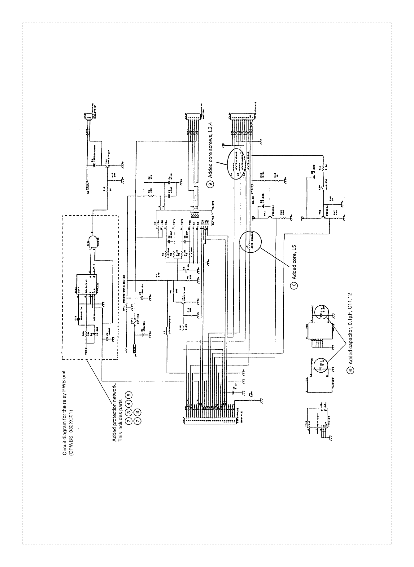
Circuit diagram for the relay PWB unit (CPWBS1082XC01)
Added protection network.
This includes parts
Added core screws, L3,4
Added core, L5
Added capacitor, 0.1µF, C11,12
 Loading...