

Page 1
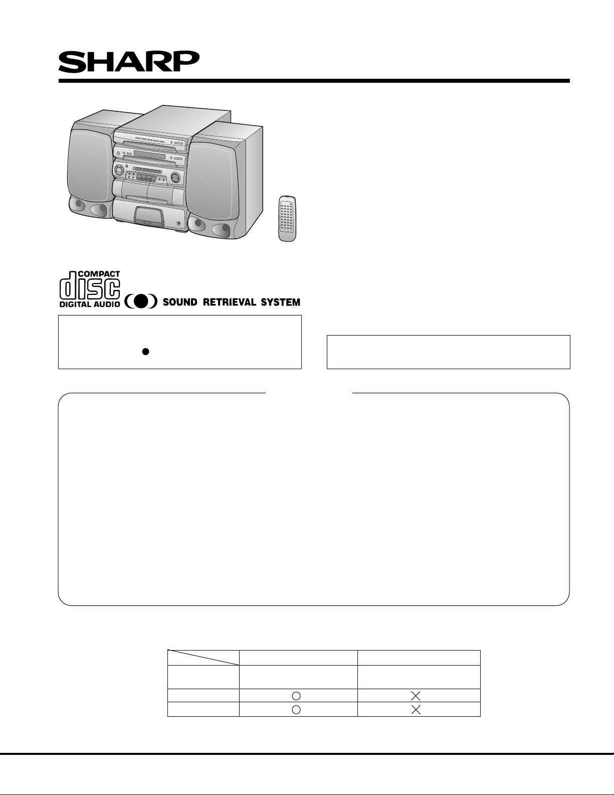
Illustration: CMS-R600X(BK)
CMS-R600X/R600XT
SER VICE MANUAL
No. S8644CMSR600X
CMS-R600X(BK)
CMS-R600XT(BK)
• SRS technology Licensed from SRS Labe. SRS technology holds
the follwing patents: U.S. Patent No. 4,748,669, U.S. Patent No.
4,841,572 and U.S. Patent No. 4,866,774.
• SRS the SRS Logo ( ) and the SOUND RETRIEVAL SYSTEM
are registered trademarks of SRS Labs, Inc.
• In the interests of user-safety the set should be restored to its
original condition and only parts identical to those specified
should be used.
CONTENTS
SPECIFICATIONS ............................................................................................................................................................. 2
VOLTAGE SELECTION..................................................................................................................................................... 2
NAMES OF PARTS ........................................................................................................................................................... 3
OPERATION MANUAL...................................................................................................................................................... 5
DISASSEMBLY.................................................................................................................................................................. 6
REMOVING AND REINSTALLING THE MAIN PARTS..................................................................................................... 8
ADJUSTMENT................................................................................................................................................................. 10
NOTES ON SCHEMATIC DIAGRAM .............................................................................................................................. 12
TYPES OF TRANSISTOR AND LED .............................................................................................................................. 12
BLOCK DIAGRAM ........................................................................................................................................................... 13
SCHEMATIC DIAGRAM / WIRING SIDE OF P.W.BOARD............................................................................................. 16
WAVEFORMS OF CD CIRCUIT...................................................................................................................................... 36
LCD DISPLAY.................................................................................................................................................................. 37
TROUBLESHOOTING (CD SECTION) ........................................................................................................................... 38
FUNCTION TABLE OF IC ............................................................................................................................................... 42
REPLACEMENT PARTS LIST/EXPLODED VIEW
Page
DIFFERENCE BETWEEN CMS-R600X(BK) AND CMS-R600XT(BK)
CMS-R600XT(BK)CMS-R600X(BK)
POWER AC 110/127/220/230-240 V, AC 220 V, 50 Hz
SOURCE 50/60 Hz
SPEAKER
SRS
SHARP CORPORATION
Page 2
CMS-R600X/R600XT
FOR A COMPLETE DESCRIPTION OF THE OPERATION OF THIS UNIT, PLEASE REFER
TO THE OPERATION MANUAL.
SPECIFICATIONS
General
Power source: AC 110/127/220/230-240 V,
(CMS-R600X) 50/60 Hz
Power source: AC 220 V, 50 Hz
(CMS-R600XT)
Power consumption: 170 W
Dimensions: Width; 360 mm (14-3/16")
Height; 390 mm (15-3/8")
Depth; 379 mm (14-15/16")
Weight: 7.3 kg (16.1 lbs.)
Amplifier section
Output power: PMPO; 300 W (total)
MPO; 84 W (42 W + 42 W)
(10 % T.H.D.)
RMS; 50 W (25 W +25 W)
(10 % T.H.D.)
Input terminals: VIDEO/AUX; 245 mV/47 kohms
Output terminals: Speakers; 8 ohms
Headphones; 8 - 50 ohms
(recommended; 32 ohms)
Tuner section
Frequency range: FM; 88 - 108 MHz
AM; 531 - 1,620 kHz
Cassette deck section
Frequency response: 50 - 14,000 Hz (Normal tape)
Motor: DC motor with electronic governor
x 1
Signal/noise ratio: 55 dB (TAPE 1, playback)
50 dB (TAPE 2, recording/
playback)
Wow and flutter: 0.15 % (WRMS)
Bias and erasure system: AC
Tape speed: 4.76 cm/sec. (1-7/8 ips.)
Heads: TAPE-1; Playback x 1
TAPE-2; Record/Playback x 1
Erase x 1
Compact disc player section
Type: 5-disc multi-play compact disc
Signal readout: Non-contact; semiconductor laser
Rotational speed: 200 - 500 rpm CLV, Approx.
Error correction: CIRC (Cross Interleave Reed-
Quantization: 16-bit linear
Filter: 4-times oversampling digital
D/A Converter: 1-bit D/A converter
Frequency response: 20 - 20,000 Hz
Dynamic range: 90 dB (1 kHz)
Wow and flutter: Unmeasurable
player
Solomon Code)
filter
(less than 0.001% W. peak)
Speaker system (CMS-R600X ONLY)
Type: 3-way type
woofer,
tweeter]
Maximum input power: 50 W
Rated power: 25 W
Impedance: 8 ohms
Dimensions: Width; 215 mm (8-1/2")
Height; 390 mm (15-3/8")
Depth; 195 mm (7-11/16")
Weight: 3.4 kg (7.5 lbs.)/each
Specifications for this model are subject to change without
prior notice.
[13 cm (5-1/8")
5 cm (2") tweeter and super
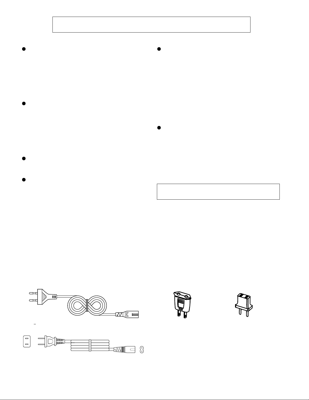
VOLTAGE SELECTION
Before operating the unit on mains, check the preset voltage. If the votage is different from your local voltage. Slide the AC power
supply socket cover by slightly loosing the screw to the visible indication of the side of your local voltage.
QACCE0005AW00 92LPLUG155A 92LPLUG027
92LCoRD577B
Figure 2 AC POWER SUPPLY CORD AND AC PLUG ADAPTOR
– 2 –
Page 3

Front panel
1. Disc Tray
2. Disc Number Select Buttons
3. Disc Skip Button
4. Open/Close Button:
5. Power Switch
6. (TUNER) Memory Button
7. Tuning Up/Down Buttons:
8. Timer Indicator
9. Remote Control Sensor
10. Reset Button
11. Band Selector Button
12. Preset and Time Up/Down Buttons:
NAMES OF PARTS
1234
567
CMS-R600X/R600XT
11
12
8910
13. Disc Number Indicator
14. Extra Bass Indicator: X-BASS
15. Record Indicator: REC
16. Function/CD Track/CD Counter/Frequency/
Preset Channel/Volume Indicator
17. CD Pause Indicator:
18. CD Play Indicator:
19. Memory Indicator
20. CD Repeat Indicator:
21. SRS Indicator (CMS-R600X ONLY)
22. FM Stereo Mode Indicator: ST
23. FM Stereo Indicator:
24. Equalizer Mode Buttons
25. Extra Bass Button: X-BASS
26. Function Selector Buttons
27. Volume Up/Down Buttons:
28. Editing Speed Selector Buttons
29. CD Pause Button
30. Record Pause Button
31. (CD/TAPE) Stop Button:
32. (CD) Track Down/Review Button:
(TAPE) Rewind Button:
33. (CD) Track Up/Cue Button:
(TAPE) Fast Forward Button:
34. (CD) Play/Repeat Button:
(TAPE) Play Button:
35. Memory/Set Button
36. Clock/Timer Button
13
5432
16
X-BASS
REC
54321
14
X-BASS
17
kHz
MHz
20
15
REC
18 19
MEMORY
ST
SRS
21
24 25 26 27
28
3029
31 32 33 34
37
38
MEMORY
22
23
35
ST
36
37. (TAPE 1) Cassette Compartment
38. (TAPE 2) Cassette Compartment
39. Level Meters
40. 3D Surround Mode Button (CMS-R600X ONLY)
41. Headphone Socket
– 3 –
39 40
41
(Illustration: CMS-R600X)
Page 4

CMS-R600X/R600XT
Rear panel
1. Speaker Terminals
2. Phono Power Supply Socket (DC 12V)
(CMS-R600X ONLY)
3. AC Power Input Socket
4. AC Voltage Selector (CMS-R600X ONLY)
5. FM 75 ohns Aerial Terminal
6. Aerial Earth Terminal
7. AM Loop Aerial Socket
8. Phono Input Sockets (CMS-R600X ONLY)
9. Video (Audio Signal) / Auxiliary Input Sockets
10. Phono/Auxiliary/Video Input Selector Switch
(CMS-R600X ONLY)
11. Span Selector Switch (CMS-R600X ONLY)
Speaker Section
12. Tweeter
13. Super Tweeter
14. Woofer
15. Bass Reflex Ducts
16. Speaker Wire
5
6
7
1
2
3
4
8
9
10
11
12
13
14
Remote Control
1. Remote Control Transmitter LED
2. 3D Surround Mode Button (CMS-R600X ONLY)
CD control section
3. Disc Number Select Buttons
4. Track Down/Review Button:
5. Disc Skip Button
6. Pause Button:
7. Random Button
8. Play/Repaet Button:
9. Stop Button:
10. Memory Button
11. Track Up/Cue Button:
12. Clear Button
Tape Control Section
13. (TAPE 1) Stop Button:
14. (TAPE 1) Play Button:
15. (TAPE 2) Rewind Button:
16. (TAPE 2) Fast Forward Button:
17. (TAPE 2) Stop Button:
18. (TAPE 2) Play Button:
19. (TAPE 2) Record Pause Button:
3
4
5
15
11
15
16 17 18
19 20
16
1
2
6
7
8
9
1210
1413
21
Tuner control section
20. Band Selector Button
21. Preset Up/Down Buttons:
22. Function Selector Buttons
23. Balance Control Buttons
24. Power Button
25. Extra Bass Button: X-BASS
26. Equalizer Mode Selector Button
27. Volume Up/Down Buttons:
– 4 –
22
23
24
25
26
27
(Illustration: CMS-R600X)
Page 5

OPERATION MANUAL
SETTING THE CLOCK
Setting method when the POWER switch is in the STAND-BY
position.1Press the MEMORY/SET button.
When the power is ON, press the CLOCK/TIMER button.
Then, within 5 seconds, press the MEMORY/SET button.
2
Press the PRESET/TIME ( or ) button to select the time
display.
PRESET/
TIME ( )
CLOCK/
TIMER
MEMORY/
SET
1
2
AM 0:00 AM 12:000:00
3
4
5
6
7
"0:00" → The 24- hour display will appear.
(0:00 - 23:59)
"AM 0:00" → The 12-hour display will appear.
(AM 0:00 - PM 11:59)
"AM 12:00" → The 12-hour display will appear.
(AM 12:00 - PM 11:59)
3
Press the MEMORY/SET button.
4
Press the PRESET/TIME ( or ) button to adjust the hour.
Press the PRESET/TIME button once to advance the time by
1 hour. Press for more than 0.5 seconds to advance continu-
ously.
When the 12-hour display is selected, "AM" will change auto-
matically to "PM".
5
Press the MEMORY/SET button.
6
Press the PRESET/TIME ( or ) button to adjust the
minutes.
Press the button for at least 0.5 seconds to advance continu-
ously.
The hour setting will not advance even if minutes advance
from "59" to "00".
7
Press the MEMORY/SET button.
The clock starts operating from "0" seconds. (Seconds are
not displayed.)
Note:
In the event of a power failure or when the AC power lead
is disconnected, the clock display will go out.
When the AC power supply is resumed, the clock display will
flash on and off to indicate that the time must be reset.
If this happens, follow steps 1 and 4 - 7 in the procedure
described above.
To change the clock time:
1
Whilst the clock is displayed, press the MEMORY/SET button.
When the power is ON, press the CLOCK/TIMER button.
Then, within 5 seconds, press the MEMORY/SET button.
2
Perform steps 4 - 7 above.
To see the time display: (When the power is ON)
Press the CLOCK/TIMER button.
The time display will appear for about 5 seconds.
To switch the time display mode:
1
Set the POWER switch to STAND-BY.
2
Whilst holding down the CLOCK/TIMER button, press the
POWER switch twice.
3
Perform steps 1 - 7 above.
In this example, the clock is set for the 24-hour
(0:00) system.
15
15
Notes concerning use:
Replace the batteries if control distance decreases or oper-
ation becomes erratic.
Periodically clean the transmitter LED on the remote control
and the sensor on the main unit with a soft cloth.
Exposing the sensor on the main unit to strong light may in-
terfere with operation. Change the lighting or the direction of
the unit.
Keep the remote control away from moisture, excessive heat,
shock, and vibrations.
0.2 m - 6 m
(8" - 20')
PREPARATION FOR USE
RESETTING THE MICROCOMPUTER
Reset the microcomputer by performing the following
procedure for the cases shown below:
To erase all of the stored memory contents, or
If the display does not function properly, or
The unit does not operate properly.
1
Set the POWER switch to STAND-BY.
2
Disconnect the AC power lead from the AC socket.
3
Press the RESET button for at least 3 seconds.
RESET
CMS-R600X/R600XT
– 5 –
 Loading...