

Page 1
CD-XP160W
ENGLISH
ENGLISH
Introduction
Thank yo u for purcha sing this SHARP product . To obtai n the be st
perform anc e from th is pro duc t, p leas e rea d th is manu al care ful ly. It
will guide you in operating your SHARP product.
Special notes
Important Instruction
E-1
Warning:
z
When the ON/STAND-BY button is set at STAND-BY position,
mains voltage is still present inside the unit. When the ON/
STAND-BY button is set at STAND-BY position, the unit may be
brought into operation by the timer mode or remote control.
z
This unit contains no user serviceable parts. Never remove covers unless qualified to do so. This unit contains dangerous voltages, always remove mains plug from the socket before any
service operation and when not in use for a long period.
z
To prevent fi re or sh ock haza rd, do not expose th is appl ianc e to
dripping or splashing. No objects filled with liquids, such as
vases, should be placed on the apparatus.
- Introducti on / Spe c ial no te s -
CAUTION
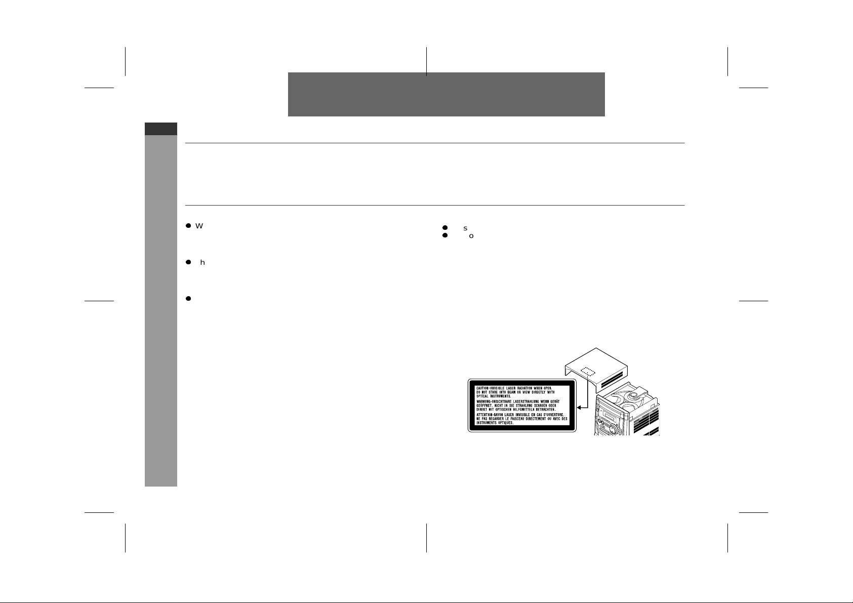
z
This product is classified as a CLASS 1 LASER product.
z
Use of controls, adjustments or performance of procedures other
than tho se sp ec ified he rei n m ay resul t in h az ar d ou s ra diation ex posure.
As the laser beam used in this compact disc player is harmful to
the eyes, do not attempt to disassemble the cabinet. Refer servicing to qualifi ed pe r s onnel only.
Laser Diode Properties
Material: GaAIAs
Wavelength: 780 nm
Emission Duration: continuous
Laser Output: max. 0.6 mW
Note:
Audio-visual material may consist of copyrighted works which must
not be reco rded w ithout th e aut hori ty of the owner of the copyright.
Please refer to the relevant laws in your country.
02/5/27 CD-XP160W(X)E1.fm
Page 2
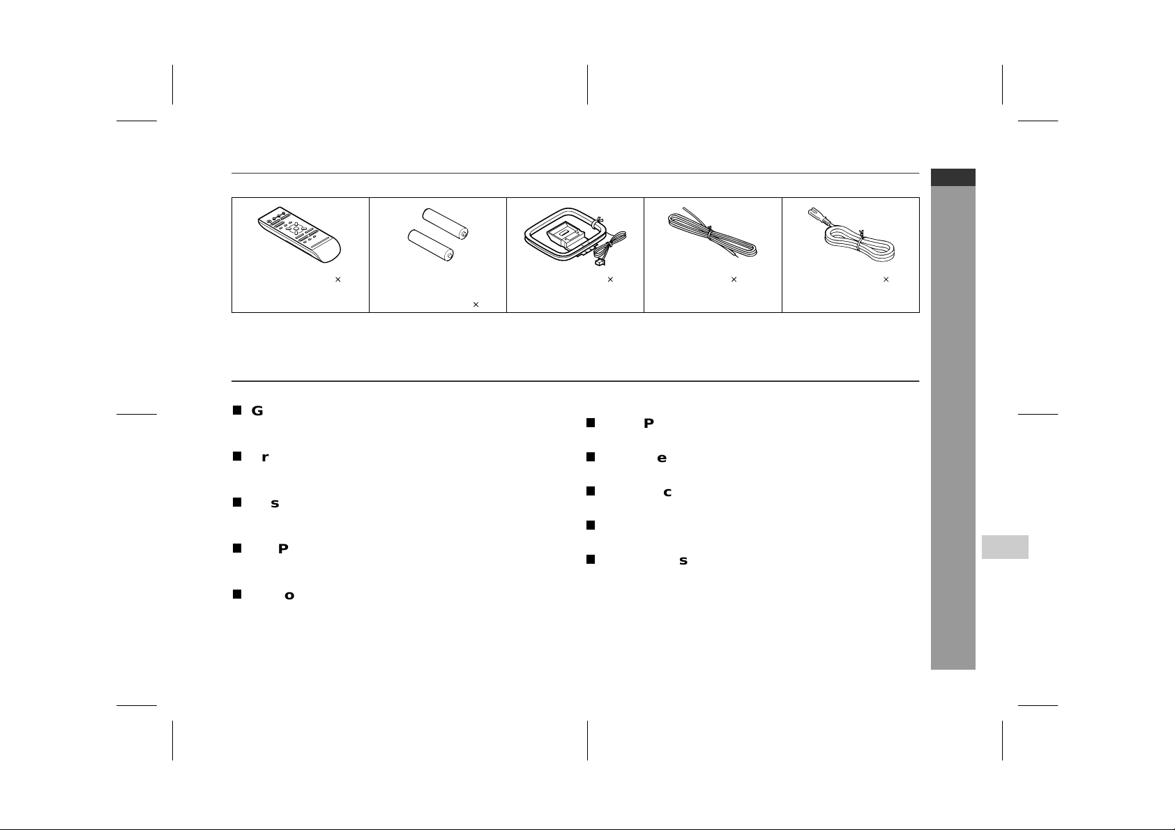
Accessories
Please confirm that the following accessories are included.
CD-XP160W
ENGLISH
Remote control 1 "AA" size battery
(UM/SUM-3, R6,
HP-7 or similar) 2
Note:
Only the above accessorie s are inc l uded.
AM loop aerial 1 AA FM aerial 1 AA AC power lead 1
Contents
Page
T
General Inform ation
Precautions . . . . . . . . . . . . . . . . . . . . . . . . . . . . . . . . . . . . . . . . . 3
Controls and indicators . . . . . . . . . . . . . . . . . . . . . . . . . . . . . .4 - 6
T
Preparation for Use
System connections . . . . . . . . . . . . . . . . . . . . . . . . . . . . . . .7 - 10
Remote control . . . . . . . . . . . . . . . . . . . . . . . . . . . . . . . . . . . . . . 11
T
Basic Operation
Sound control . . . . . . . . . . . . . . . . . . . . . . . . . . . . . . . . . . . . . . . 12
Setting the clock . . . . . . . . . . . . . . . . . . . . . . . . . . . . . . . . . . . . 13
T
CD Playb ack
Listening to a CD (CDs) . . . . . . . . . . . . . . . . . . . . . . . . . . . . 14, 15
Advanced CD playback . . . . . . . . . . . . . . . . . . . . . . . . . . . . 16, 17
T
Radio
Listening to the radio . . . . . . . . . . . . . . . . . . . . . . . . . . . . . .18,19
Page
T
Tape Playback
Listening to a cassette tape . . . . . . . . . . . . . . . . . . . . . . . . 19, 20
T
Karaoke
Playing karaoke . . . . . . . . . . . . . . . . . . . . . . . . . . . . . . . . . . . . . 21
T
Tape Recording
Recording to a cassette tape . . . . . . . . . . . . . . . . . . . . . . . 22, 23
T
Advanced Features
Timer and sleep operation . . . . . . . . . . . . . . . . . . . . . . . . . 24, 25
T
References
Troubleshooting chart . . . . . . . . . . . . . . . . . . . . . . . . . . . . . 26, 27
Maintenance . . . . . . . . . . . . . . . . . . . . . . . . . . . . . . . . . . . . . . . . 28
Headphones . . . . . . . . . . . . . . . . . . . . . . . . . . . . . . . . . . . . . . . . 28
Specifications . . . . . . . . . . . . . . . . . . . . . . . . . . . . . . . . . . . . . . 29
General Information
E-2
- Accessories / Contents -
4
02/5/27 CD-XP160W(X)E1.fm
Page 3
CD-XP160W
ENGLISH
General Information
Precautions
T
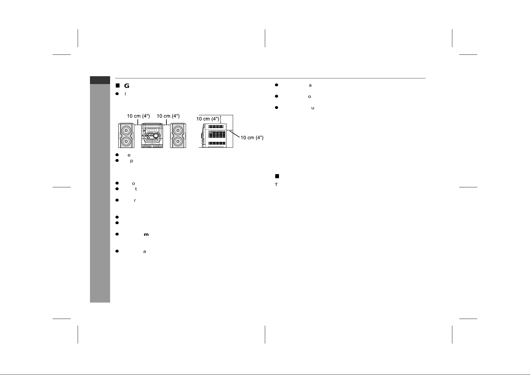
General
z
Please ensure that the equipm ent is positi oned in a well ven tilated area and en sure that there is at least 10 cm (4") of free
space along the sides, top and back of the equipment.
z
Use the unit on a firm, l evel surface fre e from vibra tion.
z
Keep the un it away from direct sunlight , strong magnetic fields,
excessive dust, humidity and electronic/electrical equipment
(home computers, facsimiles, etc.) which generate electrical
noise.
z
Do not place anything on top of the unit.
z
Do not expose the unit to moisture, to temperatures higher than
60°C (140°F) or to extremely low temperatures.
z
If your system does not work properly, disconnect the AC power
lead f rom t he wall s ocket. Plug th e AC powe r lea d back in, and
then turn on your sy stem.
- Precautions -
z
In case of an electrical storm, unplug the unit for safety.
z
Hold the AC power plug by the head when removing it from the
wall socket, as pull ing the le ad can damage i n terna l wires.
z
Do not remove the ou ter cove r, as this may res ult in e lec tric
shock. Refer internal service to your local SHARP service
facility.
z
The ventilation should not be impeded by covering the ventilation
openin gs with item s, such as new spapers , tablecloth s, curt ains,
etc.
z
No naked flame sources, such as lighted candles, should be
placed on the apparatus.
z
Attention should be drawn to the environmental aspects of battery disposal.
z
This unit should only be used within the range of 5°C - 35°C
(41°F - 95°F).
Warning:
The voltag e used must b e the sam e as that spec ified on this unit.
Using this product with a higher voltage other than that which is
specified is dangerous and may result in a fire or other type of accident ca using damag e. SHAR P wil l not be held r espon sible for any
damage re su lti ng fr om u se of thi s unit with a volt age other than that
which is specified.
T
Volume control
The sound level at a given volume setting depends on speaker efficiency, locatio n, and vario us other fa ctors. It is a dvisable to avoid
exposure to high volume levels. Do not tu rn th e volume on to full at
switch on and lis ten to musi c at mo de ra te levels .
E-3
02/5/27 CD-XP160W(X)E1.fm
Page 4

Controls and indicators
T
Front panel
1.Disc Tray . . . . . . . . . . . . . . . . . . . . . . . . . . . . . . . . . . . . . . . . 14
2.Timer Set Indicator . . . . . . . . . . . . . . . . . . . . . . . . . . . . . . . 25
3.On/Stand-by Button . . . . . . . . . . . . . . . . . . . . . . . . . . . . . . . 10
4.Tuner (Band) Button . . . . . . . . . . . . . . . . . . . . . . . . . . . . . . 18
5.CD Button . . . . . . . . . . . . . . . . . . . . . . . . . . . . . . . . . . . . 14, 22
6.CD Track Down or Fast Reverse,
Tuner Preset Down Button . . . . . . . . . . . . . . . . . . . . . . 15, 19
7.Headphone Socket . . . . . . . . . . . . . . . . . . . . . . . . . . . . . . . . 28
8.CD Stop Button . . . . . . . . . . . . . . . . . . . . . . . . . . . . . . . . . . 15
9.CD Play or Repeat Button . . . . . . . . . . . . . . . . . . . . . . . 14, 16
10. Microphone Level Control . . . . . . . . . . . . . . . . . . . . . . . . . . 21
11. Microphone Socket . . . . . . . . . . . . . . . . . . . . . . . . . . . . . . . 21
12. Tape 1 Cassette Com pa rtment . . . . . . . . . . . . . . . . . . . 20, 23
13.Tape Button . . . . . . . . . . . . . . . . . . . . . . . . . . . . . . . . . . 20, 23
14. CD Track Up or Fast Forward,
Tuner Preset Up Button . . . . . . . . . . . . . . . . . . . . . . . . . 15, 19
15. Eq ual iser Mod e Select/Extra Bas s/
Demo Mode Button . . . . . . . . . . . . . . . . . . . . . . . . . . . . 10, 12
16. Disc T ray Open/Close Button . . . . . . . . . . . . . . . . . . . . . . . 14
17. Disc Skip Button . . . . . . . . . . . . . . . . . . . . . . . . . . . . . . . . . 14
18. Volume Up and Down Buttons . . . . . . . . . . . . . . . . . . . . . . 12
19. Tuning Up Button . . . . . . . . . . . . . . . . . . . . . . . . . . . . . . . . . 18
20. Tuning Down Button . . . . . . . . . . . . . . . . . . . . . . . . . . . . . . 18
21. Tape 2 Cassette Com pa rtment . . . . . . . . . . . . . . . . . . . 20, 23
22.Tape 1 Record Button . . . . . . . . . . . . . . . . . . . . . . . . . . 22, 23
23. Tape 1 Play Button . . . . . . . . . . . . . . . . . . . . . . . . . . . . . . . . 20
24. Tape 1 Rewind Button . . . . . . . . . . . . . . . . . . . . . . . . . . . . . 20
25. Tape 1 Fast Forward Button . . . . . . . . . . . . . . . . . . . . . . . . 20
26. Tape 1 Stop/Eject Button . . . . . . . . . . . . . . . . . . . . . . . . . . . 20
27. Tape 1 Pause Button . . . . . . . . . . . . . . . . . . . . . . . . . . . . . . 20
28. Tape 2 Play Button . . . . . . . . . . . . . . . . . . . . . . . . . . . . . . . . 20
29. Tape 2 Rewind Button . . . . . . . . . . . . . . . . . . . . . . . . . . . . . 20
30. Tape 2 Fast Forward Button . . . . . . . . . . . . . . . . . . . . . . . . 20
31. Tape 2 Stop/Eject Button . . . . . . . . . . . . . . . . . . . . . . . . . . . 20
Reference page
CD-XP160W
ENGLISH
General Information
- Controls and in di ca tors -
4
02/5/27 CD-XP160W(X)E1.fm
E-4
Page 5

CD-XP160W
ENGLISH
General Information
Controls and indicators (continued)
- Controls and in di ca tors -
T
Display
1.CD Play Indicator
2.CD Repeat Play Indicator
3. FM Station Indicat or
4.AM Station Indicator
5.Disc Number I ndicators
6.Clock Indicator
7.Sleep Indicator
8.Timer Play Indicator
9.Tape 1 Record Indicator
10. CD Pause Indicator
11. FM Stere o Mo de Indicator
12. FM Stere o Receivi ng Indic at or
13. Mem or y Indicator
14. CD Random Play Indicator
15. Extra Bass Indicator
T
Rear panel
1.AC Voltage Selector . . . . . . . . . . . . . . . . . . . . . . . . . . . . . . . . 9
2. AC Power Input Socket . . . . . . . . . . . . . . . . . . . . . . . . . . . . . 9
3.FM 75 Ohms Aerial Terminal . . . . . . . . . . . . . . . . . . . . . . . 7, 8
4.FM Aerial Earth Terminal . . . . . . . . . . . . . . . . . . . . . . . . . . 7, 8
5. AM Loop Aerial Socket . . . . . . . . . . . . . . . . . . . . . . . . . . . 7, 8
6. Span Selector Switch . . . . . . . . . . . . . . . . . . . . . . . . . . . . . . 10
7. Speaker Terminals . . . . . . . . . . . . . . . . . . . . . . . . . . . . . . . 7, 8
T
Speaker system
1.Woofers
2.Bass Reflex Ducts
3.Speaker Wire
Reference pa ge
E-5
02/5/27 CD-XP160W(X)E1.fm
Page 6

T
Remote control
Reference page
10
11
1
2
3
4
5
6
12
13
14
15
16
7
8
9
17
18
19
1.Remote Control Transmitter . . . . . . . . . . . . . . . . . . . . . . . . . . 11
2.On/Stand-by Button . . . . . . . . . . . . . . . . . . . . . . . . . . . . . . . . 11
3.CD Button . . . . . . . . . . . . . . . . . . . . . . . . . . . . . . . . . . . . 14, 22
4.Tape Button . . . . . . . . . . . . . . . . . . . . . . . . . . . . . . . . . . . 20, 23
5.Memory Button . . . . . . . . . . . . . . . . . . . . . . . . . . . . . 13, 17, 19
6.CD Track Down or Fast Reverse,
Tuner Preset Down Button . . . . . . . . . . . . . . . . . . . . . . . . 15, 19
7.CD Play or Repeat Button . . . . . . . . . . . . . . . . . . . . . . . . 14, 16
8.CD Stop Button . . . . . . . . . . . . . . . . . . . . . . . . . . . . . . . . . . . 15
9.Equaliser Mode Select Button . . . . . . . . . . . . . . . . . . . . . . . . 12
10.Clock Button . . . . . . . . . . . . . . . . . . . . . . . . . . . . . . . . . . 13, 24
11. Timer Button . . . . . . . . . . . . . . . . . . . . . . . . . . . . . . . . . . . . . 24
12. Disc Number Select Buttons . . . . . . . . . . . . . . . . . . 14, 17, 22
13. Tuner (Band) Button . . . . . . . . . . . . . . . . . . . . . . . . . . . . . . . . 18
14. Programme Clear Button . . . . . . . . . . . . . . . . . . . . . . . . . . . 17
15.CD Random Button . . . . . . . . . . . . . . . . . . . . . . . . . . . . . . . 16
16. CD Track Up or Fast Forward,
Tuner Preset Up Button . . . . . . . . . . . . . . . . . . . . . . . . . . 15, 19
17. CD Pause Button . . . . . . . . . . . . . . . . . . . . . . . . . . . . . . . . . 15
18. Extra Bass Button . . . . . . . . . . . . . . . . . . . . . . . . . . . . . . . . . 12
19. Volume Up and Down Buttons . . . . . . . . . . . . . . . . . . . . . . . . 12
20. Sleep Button . . . . . . . . . . . . . . . . . . . . . . . . . . . . . . . . . . . . . 25
20
CD-XP160W
ENGLISH
General Information
- Controls and in di ca tors -
4
Buttons with " " mark in the illustration or highlighted in bold on the
right can be operated on the r emote cont rol only.
E-6
02/5/27 CD-XP160W(X)E1.fm
Page 7

CD-XP160W
ENGLISH
Preparation for Use
System connections
- System connections -
E-7
02/5/27 CD-XP160W(X)E1.fm
Page 8

T
Removing th e transport screw
Before turning the power on, be sure to remove the transport screw
on the back of the unit using a flat head screwdriver or a coin.
Note:
This scr ew is requi red wh en trans por ting th e unit again. P lease keep it
(see page 27).
T
Aerial connection
Supplied FM aerial:
Connect t he FM aeri al wire t o the FM 75 O HMS termi nal and p osition
the FM aer ial wire in the direc tion where the stron gest signal can be
received.
Supplied AM loop aerial:
Connect t he AM loop aeri al to the AM LOOP socket. Position the AM
loop aerial for optimum recept ion. Place th e AM loop aer ial on a shelf,
etc., or attach it to a stand or a wall with screws (not supplied).
Note:
Placing the aerial on the unit or near the AC power lead may cause noise
pickup. Place the aerial away from the unit for better reception.
Installing the AM loop aerial:
< Assembling > < Attaching to the wall >
External FM aerial:
Use an exter nal FM aer ial if you require better rec eption. Cons ult your
dealer.
75 ohm
coaxial
Note:
When an exter nal FM a erial is used, discon nect th e supplie d FM aer ial
wire.
cable
Wall Screws (not supplied)
External
FM aerial
T
Speaker connection
Connect the wire with the white line to the minus (-) terminal and the
plain wir e to th e plus (+) termina l.
Right speaker
Caution:
z
Use speakers with an impedance of 8 ohms or
more, as lower impedance speakers can damage
the unit.
z
Do not mistake the r ight and the left channels. The
right spe ak er is the on e on the right sid e w he n yo u
face the unit.
z
Do not let the bare speaker wires touch each
other.
z
Do not allow any objects to fall into or to be placed
in the bass reflex ducts.
z
Do not stand or sit on the speakers. You may be injured.
Notes:
z
The s peaker gr illes ar e not removable.
z
There is no physical distinction between the right and left speakers.
Left speaker
Incorrect
CD-XP160W
ENGLISH
- System connections -
Preparation for Use
4
02/5/27 CD-XP160W(X)E1.fm
E-8
Page 9

CD-XP160W
ENGLISH
Preparation for Use
System connections (continued)
- System connections -
T
Setting th e AC voltage selector
Check the setting of the AC voltage selector located on the rear
panel before plugging the unit into a wall socket . If necessary, adj ust
the selector to correspond to the AC power voltage used in your
area.
T urn the selector with a screwdriver until the appropriate voltage number appears in the window (110 V, 127 V, 220 V or 230 V
- 240 V AC).
T
Connecting the AC power lead
After checking all the connections have been made correctly, connect the AC power lead to the AC power input socket, then plug the
AC power lead of this unit into the wall socket. If yo u plug in the unit
first, th e un it w ill enter th e de m on str a tion mode (s e e pag e 10).
Notes:
z
Unplug the AC power lead from the wall socket if the unit will not
be in use for a prolonged period of time.
z
Nev er us e a po w er le ad oth e r than the on e s uppl ie d. Other wi s e, a
malfunction or an accident may occur.
AC Plug Adaptor
In areas (or countries) where a wall socket as shown in illustration
is used, connect the unit using the AC plug adaptor supplied with
the unit, as illustrated. The AC plug adaptor is not included in areas
where the wall socket and AC power plug can be directly connected
(see illustration ).
E-9
02/5/27 CD-XP160W(X)E1.fm
Page 10

T
Setting the FM/AM span selector
The International Telecommunication Union (ITU) has established
that memb er cou nt ries shou ld mai ntai n ei the r a 100 kH z or a 50 kHz
interval between broadcasting frequencies of FM stations and 10
kHz or 9 kHz for AM station. The illustration shows the 50/9 kHz
zones (regions 1 and 3), and the 100/10 kHz zone (region 2).
Before using the u ni t, set the
panel) to the interval (span) of your area.
To change the tuning zone:
1 Press the ON/STAND-BY button to enter the stand -by mode.
2 Set the SPAN SELECTOR switch (on the rear panel) as follows.
z
For 100 kHz F M interva l (10 kH z i n AM) 100/10
z
For 50 kHz FM interval (9 kHz in AM) 50/9
3 Whilst pressing down the TUNER (BAND) button and the DISC
SKIP button , press th e ON/S TAND-B Y butto n until "C LEAR" ap pears.
Caution:
This operation will erase all data stored in memory including clock,
timer settings, tuner preset, and CD programme.
SPAN
SELECTOR switch (on the rear
T
Demonstration mode
The first time the uni t is plugged in , the
unit will enter the demonstration mode.
You will see words scroll.
To cancel the demonstration mode:
When the unit is in the power stand-by mode (demonstration mode),
press the EQUALIZER/X-BASS/ DEMO button. The demonstration
mode will be cancelled and the display
To return to the demonstration mode:
When th e unit is in the power st and-by mode, press the EQUALIZER/X-BASS/DEMO button again.
Note:
When the power is on, the EQUALIZER /X-BASS/DE MO button can
be used to select the pre-programmed equaliser and extra bass
modes.
T
To turn the power on
Press the ON /S TAND-BY button to turn th e pow er on .
After use:
Press the ON/STAND-BY button to enter the power stand-by
mode.
will di sappear
.
CD-XP160W
ENGLISH
- System connections -
Preparation for Use
4
02/5/27 CD-XP160W(X)E1.fm
E-10
 Loading...