

Sharp Carousel RK-42S24, Carousel RK-51K30, Carousel RK-51S27, Carousel RK-51W30, Carousel RK-51S30 Installation Instructions Manual
Page 1

®
INSTALLATION INSTRUCTIONS
For Sharp Carousel
®
Built-in Kit
Models RK-42S24, RK-51S27,
RK-51K30, RK-51S30 or RK-51W30.
THIS KIT IS UL APPROVED TO ALLOW CERTAIN MICROWAVE OVENS
TO BE INSTALLED ABOVE CERTAIN CONVENTIONAL/CONVECTION
WALL OVENS. PLEASE SEE THE OPERATION MANUAL REGARDING
APPROVED BUILT-IN APPLICATIONS.
IMPORTANT:
This Built-in Kit is designed for and approved only for those Sharp
Microwav e Ovens specifying Built-In Kit RK-42S24, RK-51S27, RK-51K30,
RK-51S30 or RK-51W30 on the rating label on the left side wall of the
oven cavity.
The cabinet or wall opening must be within the following dimensions:
RK-42S24 HEIGHT : 15
WIDTH : 22
DEPTH : minimum 19
*RK-51S27, *RK-51K30, HEIGHT : 16
*RK-51S30 & *RK-51W30 WIDTH : 24
DEPTH : minimum 20"
* IF YOUR LOWER CONVENTIONAL OVEN IS NOT LISTED IN THE OPERATION MANUAL OF
THE MICROWAVE OVEN AS AN APPROVED MAKE AND MODEL, THEN DO NOT INSTALL
THE MICROWAVE OVEN ABOVE IT OR IN ANY AREA WHERE HEAT AND STEAM ARE
GENERATED; FOR EXAMPLE, NEXT TO OR ABOVE A CONVENTIONAL RANGE.
S= Stainless, K=Black, W=White
PLEASE READ THESE INSTRUCTIONS THOROUGHLY BEFORE
BEGINNING INSTALLATION!
• Be sure to DISCONNECT THE PLUG of the microwave oven from the
electrical outlet before installing the Built-in Kit. Remove the Carousel
turntable from the oven cavity.
• Because the kit includes metal par ts, due caution should be used in
handling and installation to avoid the possibility of injury.
11
/16" to 16"
1
/16" to 22 3/8"
1
/4"
3
/4" to 17"
3
/8" to 24 11/16"
NO. PART NAME QTY
PART CODE
1 FRAME ASSEMBLY 1
S24 - FDECAB015MRY0
S27 - FDECAB008MRY0
S30 - FDECAB018MRY0
K30 - FDECAB019MRY0
W30 - FDECAB020MRY0
2 EXHAUST DUCT ASSEMBLY 1
S24 - FDUC-B019MRK0
S27 - FDUC-B032MRK0
S30 - FDUC-B032MRK0
K30 - FDUC-B032MRK0
W30 - FDUC-B032MRK0
3 POWER SUPPLY CORD 1
BOX ASSEMBLY
FCOVHB004MRK0
4 REAR DUCT 1
PDUC-B072MRP0
5 SCREW A 3
XCTSD40P10000
6 SCREW B 2
XTTSD40P30000
7 SCREW C 4
S24 - LX-CZB012MRE0
S27 - LX-CZB012MRE0
S30 - LX-CZB012MRE0
K30 - LX-CZB014MRE0
W30 - LX-CZB015MRE0
1
4
5
2
6
1
3
7
Page 2

STEP 1 CABINET OR WALL OPENING
The opening in the wall or cabinet must be within the
following dimensions:
RK-42S24:
*RK-51S27,
*RK-51K30,
*RK-51S30 &
*RK-51W30
Outlet should NOT be in the shaded area as indicated
on Sketch 1.
NOTE 1: If the dimension of DEPTH (C) is more than
21", the outlet location may be any area on the
rear wall.
NOTE 2: The floor of the opening should be constructed
of plywood strong enough to support the
weight of the oven and floor load (about 100
pounds). The floor should be level for proper
operation of the oven. Be sure to check the
local building code as it may require that the
opening be enclosed with sides, ceiling and
rear partition. The proper functioning of the
oven does not require the enclosure.
HEIGHT : 15
WIDTH : 22
DEPTH : minimum 19
HEIGHT : 16 3/4" to 17"
WIDTH : 24
DEPTH : minimum 20"
11
/16" to 16"
1
/16" to 22 3/8"
1
3
/8" to 24 11/16"
/4"
6"
4"
A
4"
B
C
Sketch 1
STEP 2 EXHAUST DUCT ASSEMBLY INSTALLATION
1. Place the EXHAUST DUCT ASSEMBLY in the
opening. When the EXHAUST DUCT ASSEMBLY
is in the opening correctly, its flanges will be tightly
against the lower edge of the opening. See
Sketch 2.
2. Secure the EXHAUST DUCT ASSEMBLY with two
SCREWS B. See Sketch 2.
SCREW B
EXHAUST
DUCT ASSEMBLY
SCREW B
Sketch 2
2
Page 3
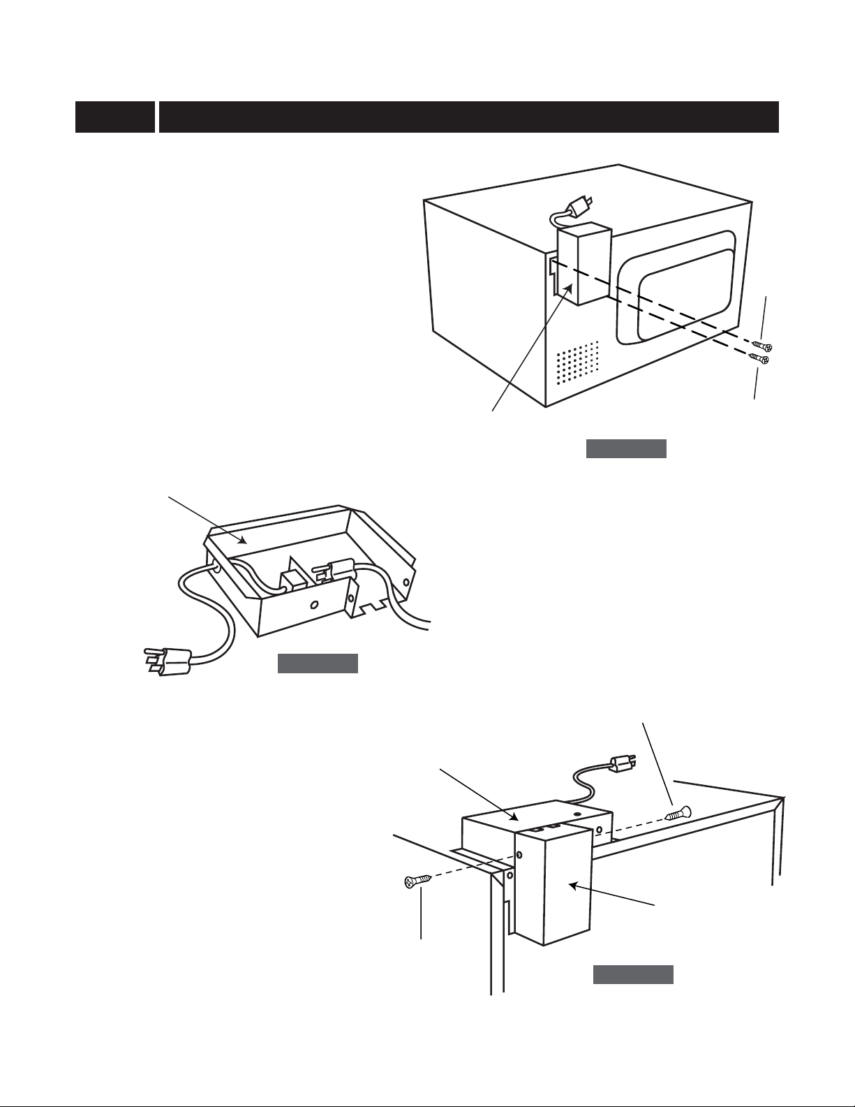
STEP 3 POWER SUPPLY CORD BOX ASSEMBLY AND REAR DUCT INSTALLATION
1. Roll the po wer supply cord into the REAR DUCT.
2. Remove the screw
cabinet. Secure the left flange of the REAR
DUCT with the screw
and secure the right flange of the REAR DUCT
with SCREW A. See Sketch 3.
3. Plug the oven power supply cord into the
POWER SUPPLY CORD BOX ASSEMBLY
receptacle. See Sketch 4.
4. Slide the POWER SUPPLY CORD BOX
ASSEMBLY into the REAR DUCT and secure
the POWER SUPPLY CORD BOX ASSEMBLY
and REAR DUCT with two SCREWS A. See
Sketch 5.
POWER SUPPLY
CORD BOX ASSEMBLY
✪ from left top of outer
✪ removed from the oven
SCREW A
REAR DUCT
Sketch 3
✪
Sketch 4
SCREW A
POWER SUPPLY
CORD BOX ASSEMBLY
REAR DUCT
SCREW A
Sketch 5
3
Page 4
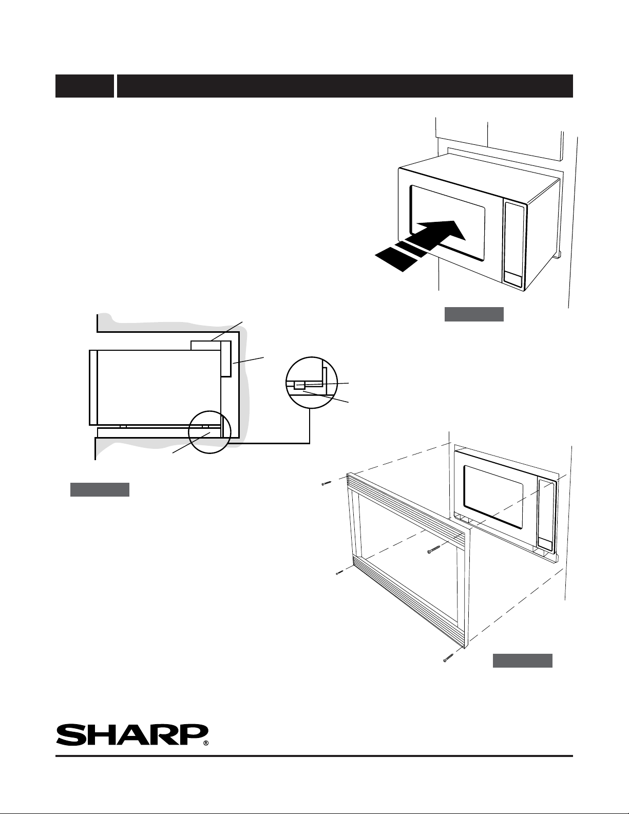
STEP 4 FRAME INSTALLATION
1. Place the ov en adjacent to the wall or cabinet opening. Plug the POWER
SUPPLY CORD BOX ASSEMBLY cord into the electrical outlet.
2. Carefully guide the assembled oven into the prepared opening. Slide
the oven on the EXHAUST DUCT ASSEMBLY. See Sketch 6. Avoid
pinching the cord between the oven and the wall. Adjust the position of
the oven so that the feet of the oven are fitted into the recesses of the
EXHAUST DUCT ASSEMBLY. See Sketch 7.
3. Position the FRAME ASSEMBL Y to be square with the oven. Carefully
place the FRAME ASSEMBLY on the oven. Check that it is level and
then secure with two SCREWS C. See Sketch 8.
4. Secure the bottom portion of the FRAME ASSEMBLY with the two
remaining SCREWS C. See Sketch 8.
POWER SUPPLY CORD BOX
ASSEMBLY
REAR DUCT ASSEMBLY
Sketch 6
Sketch 7
OVEN
EXHAUST DUCT ASSEMBLY
FOOT
RECESS
SCREW C
SCREW C
SCREW C
Sketch 8
SCREW C
SHARP ELECTRONICS CORPORATION
Sharp Plaza, Mahwah, New Jersey 07430-2135
For any other assistance or information about this kit, please call
Sharp’s Customer Assistance Center at
1-800-BE-SHARP (1-800-237-4277)
TINSEB279MRR0
Printed in U.S.A.
4
 Loading...