

Page 1
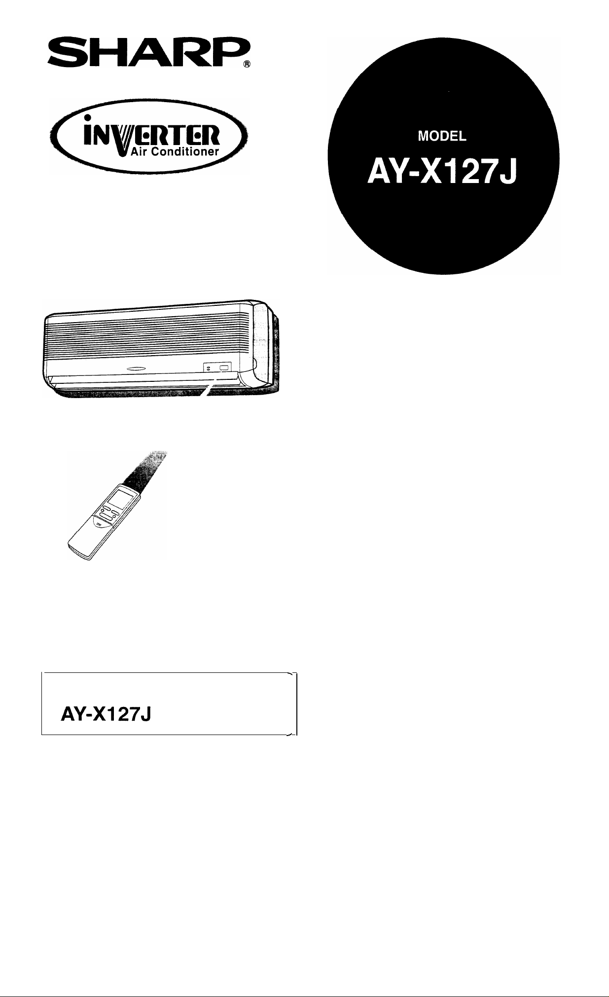
SPLIT TYPE
ROOM AIR CONDITIONER
OPERATION MANUAL
INDOOR UNIT
Thank you for purchasing this Sharp product. Please read this manual carefully before
operating the air conditioner, and keep this manual and the Installation Manual as handy
references.
OUTDOOR UNIT
AE-X127J
Page 2
l
PRECAUTIONS
l
SPECIFICATIONS
ON SAVING ENERGY
l
PART NAMES
l
USING THE REMOTE CONTROL . . . . . . . . . . . . . 5
l
BASIC OPERATION
. . . . . . . . . . . . . . . . . . . . . . . . . . . . . . . . . . . . . . . . .
. . . . . . . . . . . . . ..*.....................
. . . . . . . . . . . . . . . . . . . . . .
. . . . . . . . . . . . . . . . . . . . . . . . . . . . . . . . . . . . . . . . . . . .
. . . . ..a...........................
1
AIR FLOW DIRECTION . . . 8
OPERATION
l FULL POWER MODE
2
3
7
l
ONE-HOUR TIMER
l
AUXILIARY MODE
l
MAINTENANCE
l
BEFORE CALLING FOR SERVICE . . . . . . . . . . . . 14
. . . . . . . . . ..*.........................
. . . . . . . . . . . ..*....................*...
. . . . . . . . . . . . . . . . . . . . . . . . . . . . . . . . . . . . . . . . . .
. . . . . . . . . . . . . . . . . . . . . . . . . . . . . . . . . ...*
. . ..*............................
WARNING
1
.
Using a power circuit with improper voltage and frequency can result in damage to the unit and
possibly fire.
Use a circuit with a 230-240 volt
2
.
Open a window or door periodically to
.
Inserting objects into the unit could result in injury due to rotation of the high-speed fans.
3
.
4
Pulling the power cord might result in damage or electrical shock. Do not misuse the power cord.
.
This appliance is not intended for use by young children or infirm persons without supervision.
5
Young children should be supervised to ensure that they do not play with the appliance.
rating.
the room, especially when using gas appliances.
9
11
11
12
13
.
When using the air conditioner for infants, children, elderly, bedridden, or disabled people- make
6
sure
the room temperature is suitable for those in the room.
.
Always use a fuse with the correct current rating.
7
.
Use only the manufacturer specified power cord (parts code; QACC-A234JBEO) for its replacement.
8
Replacement should be conducted by a service centre approved by Sharp.
This unit is designed for human comfort. Do not use for applications such as a kennel or
nursery to raise animals or plants.
For your safety, ensure that your new air conditioner is installed by a licensed electrical
contractor with accordance with the SAA WIRING RULES.
CAUTION
l
To ensure that your warranty is not cancelled, both the indoor/outdoor units and supply/ interconnect-
ing cables must be installed by a licensed air conditioning contractor.
LOCATION
l
Do not locate the unit where there is excessive dust, fumes or moisture in the air.
INSTALLATION
l
Do not attempt to install or remove the unit yourself. Consult a licensed air conditioning contractor.
REMOVAL
Indoor unit
Outdoor unit
Rated A.C.
(V)
Rated frequency (Hz)
Cooling capacity (kw)
Heating capacity (kw)
AY-X127J
AE-X127J
230-240
50
1
*When tested in accordance
AS 1861.1.
with
Page 3
OPERATING TEMPERATURE RANGE
INDOOR TEMP. OUTDOOR TEMP.
upper limit
COOLING
HEATING
lower limit
limit
lower limit
32°C D.B.
23°C W.B.
21°C D.B.
15°C W.B.
27°C D.B.
20°C c
46°C D.B.
21°C D.B.
21°C D.B.
-95°C W.B.
D.B.=Dry-bulb W.B.=Wet-bulb
WHEN POWER FAILURE OCCURS
This air conditioner has a back-up function in case of power failure during operation.
After power recovery, the unit will automatically restart in the same settings which were
before the power failure, except for timer operation settings.
If the timers are set, they will need to be reset after power recovery.
PREHEATING FUNCTION
In the HEAT operation, the indoor fan might not start for two to five minutes after the unit is turned on
to prevent the air from circulating before the unit is sufficiently warmed up.
DE-ICING FUNCTION
l When ice forms on the heat exchanger in the outdoor unit during the HEAT operation, an
automatic de-icer operates for about 5 to
and outside fans stop operating.
l
A hissing sound may be heard originating from the indoor unit during de-icing.
l
After de-icing is completed, the unit automatically resumes operation in the HEAT mode.
minutes to remove the ice. During de-icing, the inside
A built-in protective device
might prevent the unit from
operating when used out of
this range.
Condensation might form on
the air outlet when the unit
operates continuously in the
COOL or the DRY mode
when the humidity is over 80
percent.
HEATING EFFICIENCY
l
The unit employs a heat pump that draws heat from the outside air and releases it into the room.
The outside air temperature therefore greatly affects the heating efficiency.
l If the outside temperature is unusually low, you may require additional heating to maintain the
desired room temperature.
l
On very cold days, it may take some time to heat the entire room, you may need to use the “full
power” feature to speed up heating.
Below are some simple ways to save energy when you use your air conditioner.
SET THE CORRECT TEMPERATURE
Setting the temperature 1
temperature can result in a 10 percent saving in electricity.
l
Setting the temperature colder than necessary during cooling will result in excess power consump-
tion.
higher in COOL mode, and 2°C lower in HEAT mode than the desired
KEEP OUT DIRECT SUNLIGHT AND DRAFTS
l
Keeping out direct sunlight when cooling will aid in reducing the power consumption.
l
Close the windows and doors when heating and cooling the room.
SET PROPER AIR FLOW DIRECTION TO OBTAIN THE BEST AIR CIRCULATION
KEEP FILTER CLEAN TO ENSURE THE MOST EFFICIENT OPERATION
MAKE MOST OF THE TIMER OFF FUNCTION
UNPLUG THE POWER CORD WHEN THE UNIT IS NOT TO BE USED FOR AN
EXTENDED PERIOD
l
The indoor unit still consumes a small amount of power when it is not operating.
Page 4
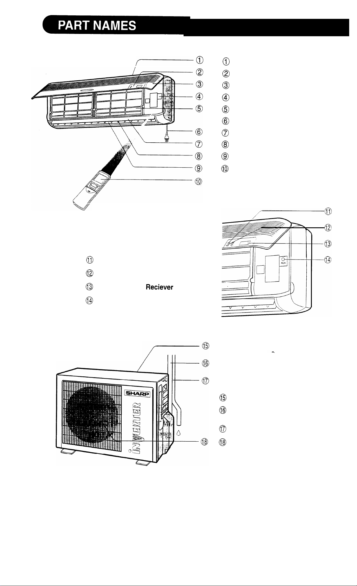
INDOOR UNIT
Inlet (Air)
Indicator Panel
Hinged Front Panel
Operation Panel
Air Filters
Power Supply Cord
Vertical Adjustment Louvre
Horizontal Adjustment Louvres
Outlet (Air)
Remote Control
Hold the bottom corners of the
open panel and gently pull out-
wards.
Operation Lamp (red)
Timer Lamp (yellow)
Remote Control
AUX. Button
OUTDOOR UNIT
Window
Inlet (Air)
Refrigerant Tubes and Intercon-
necting Cord
NOTE:
Drainage Hose
Outlet (Air)
Actual units might vary slightly from those shown above.
3
Page 5
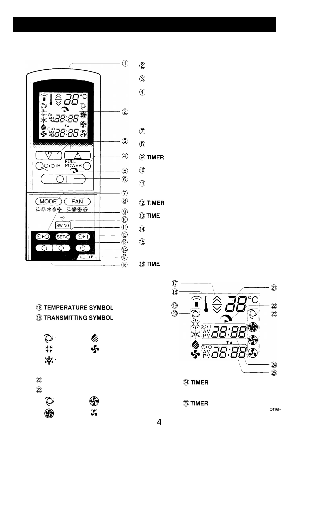
REMOTE CONTROL
@TRANSMITTER
DISPLAY (Liquid Crystal Display)
THERMO. (Thermostat) Button
FULL POWER OPERATION Button
@ONE-HOUR TIMER Button
@ON/OFF Button
MODE Button
FAN Button
SWING Button
TIMER SET/CANCEL Button, and CLOCK
SET Button
CLOCK Button
Indicates BATTERY COMPARTMENT is
below this mark
L.C.D. REMOTE CONTROL DISPLAY
@THERMOSTAT
DRY MODES
SETTING FOR AUTO AND
OFF Button
ON Button (for setting the timer)
ADVANCE Button
REVERSE Button
(for setting the timer)
@MODE SYMBOLS
AUTO
: HEAT
.
COOL
@TEMPERATURE INDICATOR
FULL POWER OPERATION MODE SYMBOL
FAN SPEED SYMBOLS
: AUTO
: HIGH
: DRY
: FAN ONLY
: LOW
:
0
SOFT
ON INDICATOR/CLOCK
Indicates the timer-on time or current time.
OFF INDICATOR
Indicates the timer-off time or
hour timer setting.
Page 6
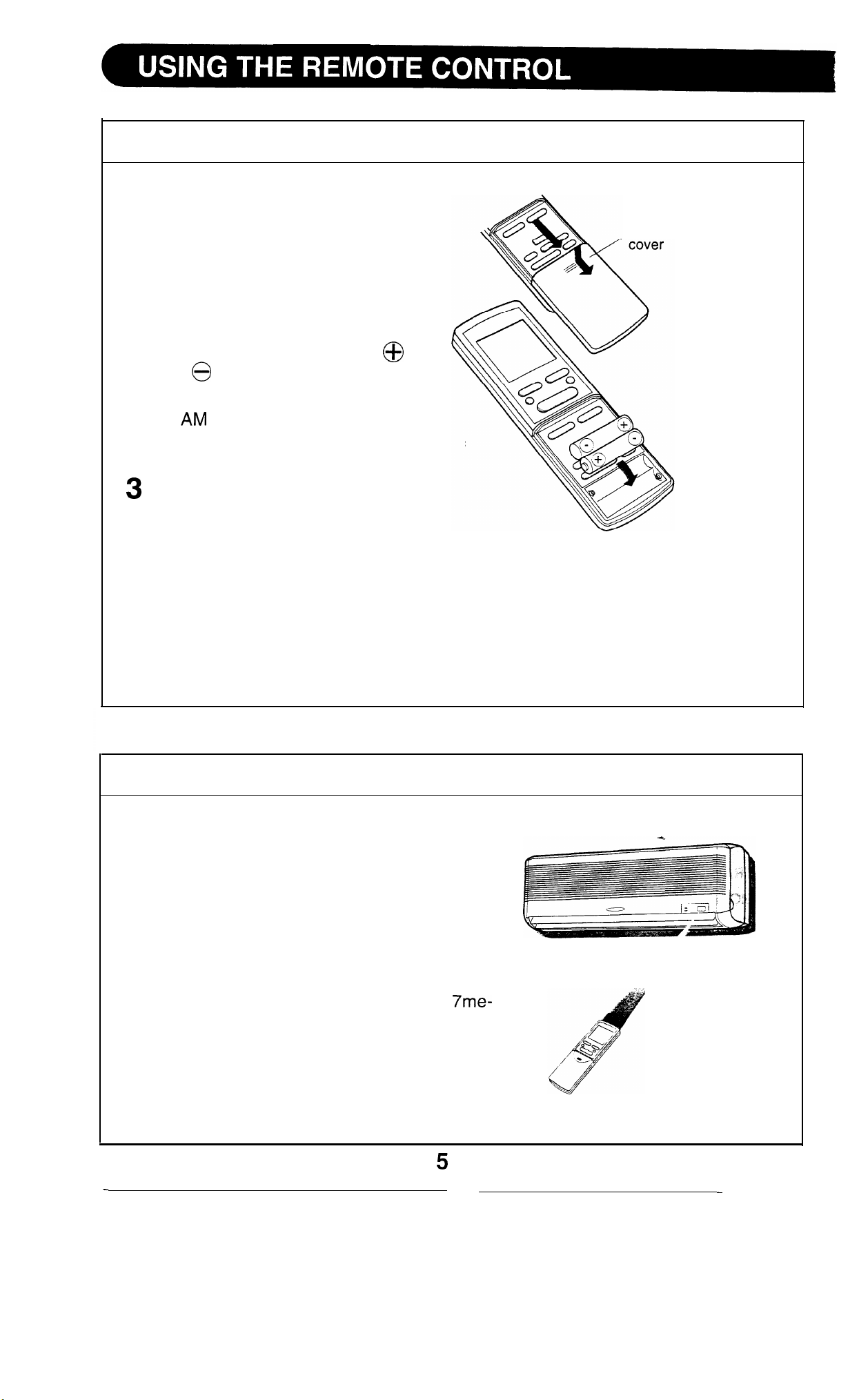
LOADING BATTERIES
1 Slide open the remote control
cover as shown.
Now continue to pull the cover in
the same direction to completely
remove it.
2
Insert the batteries in the com-
partment, making sure the
and
aligned.
polarities are properly
Use two size-AAA (R03) batteries.
remote control
l
6:00 will appear on the
display when the batteries are
properly loaded.
Replace the cover.
NOTES:
l
The battery life is approximately one year with normal use.
l
When you replace the batteries, always use two new ones of the same type.
l If the remote control does not operate normally after replacing the batteries,
take out the batteries and replace them again after 30 seconds.
l If you will not be using the unit for a long time, remove the batteries from the
remote control.
HOW TO USE THE REMOTE CONTROL
Point the remote control towards the indoor
unit’s receiver window and press the de-
sired button. A beep will sound when the
indoor unit receives the signal.
l
Make sure no objects, such as curtains, are
between the remote control and the indoor
unit.
l The remote control can operate up to
ters away, when the batteries are in good
condition.
Page 7
CAUTION
Do not
expose the receiver window on the indoor unit to strong, direct sunlight, which
can adversely affect its operation. In such case, close the curtains to block the sunlight.
Use
of a fluorescent lamp with a quick starter in the same room might interfere with
transmission of
The indoor unit might be affected by signals emitted from the remote control of a
television, VCR or other equipment used in the same room.
Do not leave the remote control in direct sunlight or near a heater. Also, protect the unit
and remote control from moisture and shock which
the
signal.
can
discolour or damaae them.
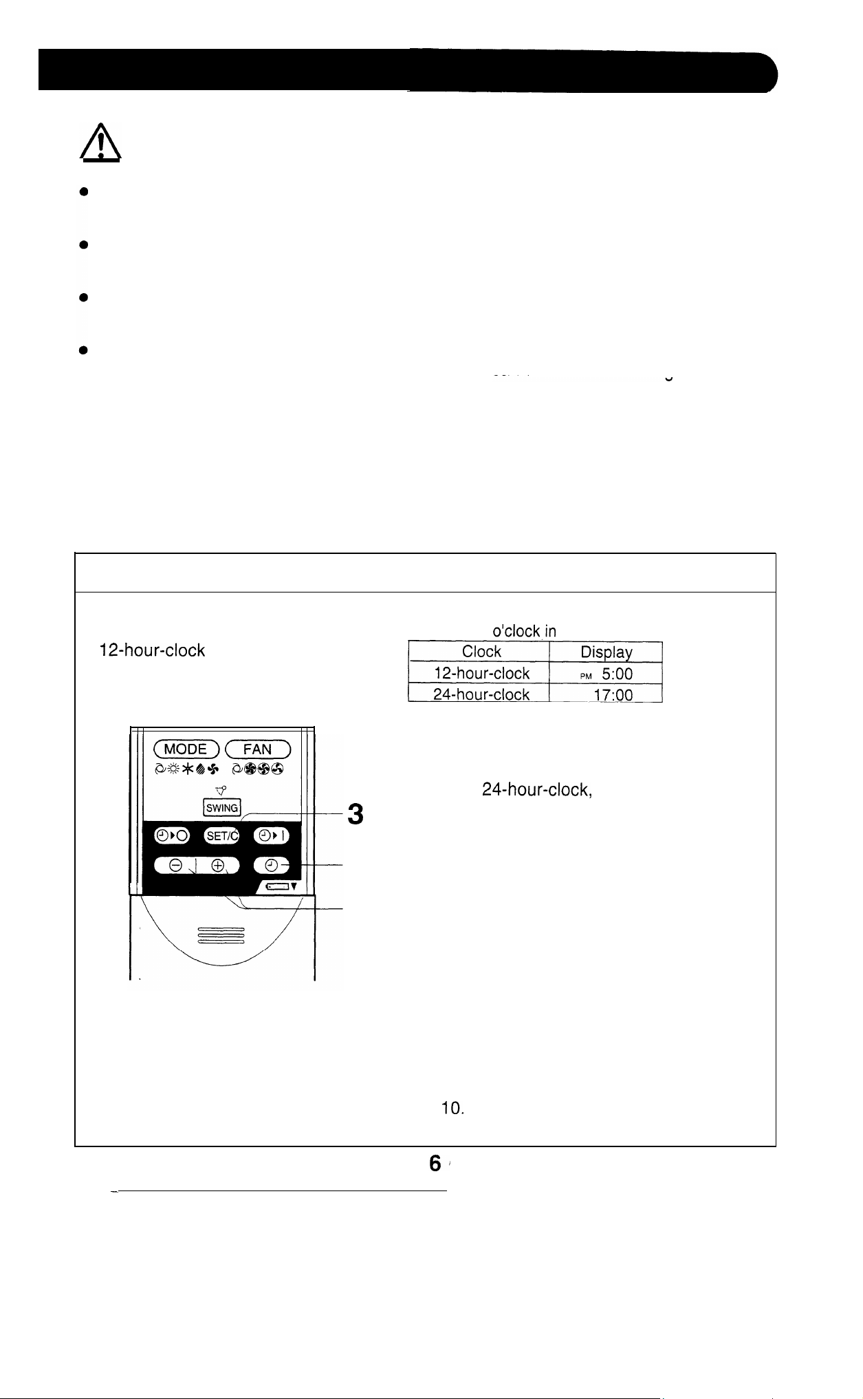
SETTING THE CURRENT TIME
There are two setting modes:
1
2
Example: 5
1
To set 12-hour-clock, press the CLOCK
button once.
To set
button twice.
2
Press the TIME ADVANCE or-REVERSE
buttons to set the current clock time.
l
Hold the buttons down to fast-forward
or reverse the time on the display.
3
Press the SET/C button.
l
The colon (:) blinks to indicate that the
clock is functioning.
the afternoon
press the CLOCK
NOTE:
l The time cannot be set, if the on or off
timers have programmed.
Please refer to “Timer Operation” on page 9
and
Page 8
V
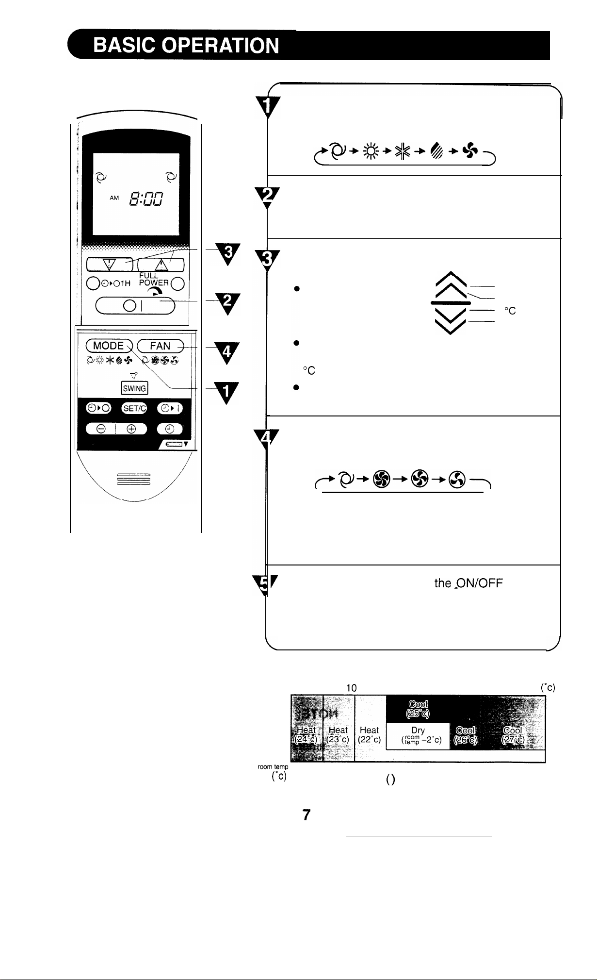
Press the MODE button to select the
operation
mode.
AUTO HEAT COOL DRY FAN ONLY
Press the ON/OFF button to start operation.
l
The
red
OPERATION
lamp on the indoor unit will
light up.
Press the THERM0 button to set the desired
temperature.
In the AUTO and DRY
mode, the indicator bars
represent changes in
temperature.
2°C higher
1°C higher
1 “C lower
2°C lower
In the manual HEAT and COOL mode, the tem-
perature can be set within the range of 18 to 32
In the
FAN ONLY
mode, the temperature cannot
be set.
Press the FAN button to set the desired fan
speed.
AUTO HIGH
l In the DRY mode, the fan speed cannot be
changed.
l In the FAN ONLY mode, the fan speed AUTO
cannot be set.
LOW SOFT
button
again.
l
The red OPERATION lamp on the indoor unit will
go out.
TIPS ABOUT AUTO MODE:
in the AUTO MODE, the
temperature setting and
mode (HEAT, COOL or
DRY) are automatically selected depending on the
room temperature and out-
door temperature when the
unit is turned on.
26
21
0
18
31
34
The figures in are temperature settings.
outdoor temp
Page 9
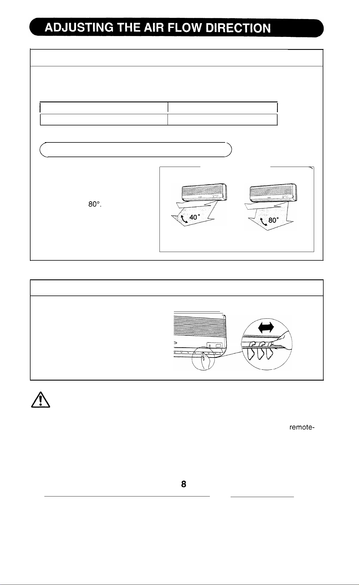
VERTICAL AIR FLOW
The direction of the air flow is automatically preset
for the optimum effect in each
mode as follows;
COOL and DRY mode
HEAT and FAN ONLY mode
Horizontal air flow
Diagonal air flow
HOW TO ADJUST THE AIR FLOW DIRECTION
Press the SWING button of the
remote control once.
l
The vertical adjustment louvre
will swing continuously within
the range of 80’.
Press the SWING button again
when the desired position is
reached and the louvre will stop.
COOL and DRY mode HEAT and FAN ONLY mode
The range is narrower to
prevent condensation
from forming.
Adjustment range
The range is wider for increased air circulation.
HORIZONTAL AIR FLOW
Hold the horizontal adjustment
louvres as shown and adjust
the air flow direction.
CAUTION
Never attempt to adjust the vertical adjustment louvres manually.
l
Manual adjustment of these louvres can cause the unit to malfunction when
controlled later.
l
When the vertical adjustment louvres are adjusted completely downward during COOL
and DRY modes for an extended period of time, condensation might form.
Page 10
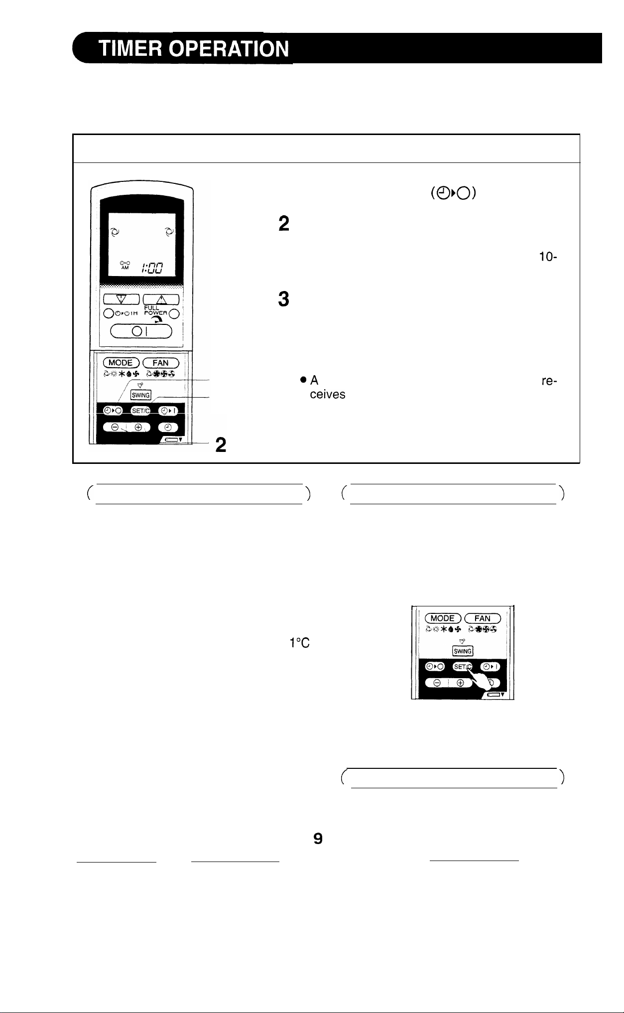
NOTE:
Before setting the timer, ensure that the current time is properly set.
TIMER OFF
1
Press the TIMER OFF
The TIMER OFF indicator will blink; press the
TIME ADVANCE or REVERSE buttons to set
the desired time. (The time can be set in
minute increments.)
Point the remote control at the receiver window
on the indoor unit, and press the TIMER SET
(SET/C) button.
l The yellow TIMER lamp on the indoor unit
lights up.
button.
1
3
TIPS ABOUT TIMER OFF OPERATION
When the TIMER OFF mode is set, the
room temperature is automatically ad-
justed to prevent the room from becom-
ing too hot or too cold while you sleep.
(Auto sleep function)
COOL/DRY MODE:
l
One hour after the timer operation
has begun, the temperature rises
higher than the thermostat setting.
beep will sound when the indoor unit
the signal.
TO CANCEL TIMER MODE
Press the TIMER CANCEL (SET/C) but-
ton.
l
The yellow TIMER lamp on the indoor
unit will go out.
l
The current time will be displayed on
the remote control.
HEAT MODE:
l
One hour after the timer operation
has begun, the temperature drops
3°C lower than the thermostat
setting.
NOTE:
Auto sleep function will not activate dur-
ing the FAN ONLY mode.
NOTE:
l Both timers will be cancelled when
the SET/C button is pressed.
TO CHANGE A TIME SETTING
First, cancel the TIMER, then set it
again.
Page 11
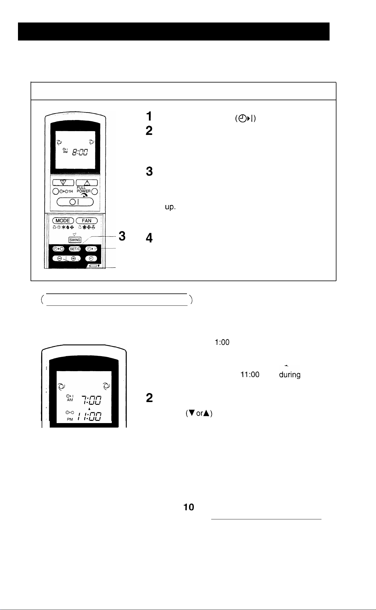
TIMER ON
1
2
Press the TIMER ON
button.
The TIMER ON indicator will blink; press the TIME
ADVANCE or REVERSE buttons to set the desired time. (The time can be set in IO-minute increments.)
Point the remote control at the receiver window on
the indoor unit and press the TIMER SET (SET/C)
button.
l
The yellow TIMER lamp on the indoor unit lights
l
A beep will sound when the indoor unit receives
the signal.
Select the operation condition.
l The unit will turn on prior to the setting time to
allow the room to reach the desired temperature
by the programmed time. (Awaking function)
COMBINED USE OF ON AND OFF TIMERS
You can combine the use of the ON and OFF timers.
Example:
Stop operation at 1
(using the same settings) to obtain the desired room
temperature by 7:00 a.m.
1 Set the TIMER OFF to
tion.
Set the TIMER ON to 7:00 a.m.
The arrows
and the TIMER OFF indicator shows which timer will
activate first.
p.m. and resume operation
p.m.
opera-
between the TIMER ON indicator
NOTES:
l You cannot program the ON and OFF timers to different temperatures or other
settings.
l
Either timer can be programmed prior to the other.
l
The timers will only operate once.
Although the last timer setting will be memorised, the timer must be selected each time
it is required.
Page 12

In this mode, the air conditioner works at maximum power operation. This mode
makes the room cool or warm rapidly.
To activate the FULL POWER mode, press
the FULL POWER button during operation.
l
FULL POWER mode symbol
is dis-
played on the remote control.
l
The temperature display disappears.
l
This mode will be automatically cancelled
after one hour’s operation.
To cancel the FULL POWER mode, press the
FULL POWER button again.
NOTES:
l
You cannot use the FULL POWER mode dur-
ing the DRY or the FAN ONLY mode.
l You cannot set the temperature during the
FULL POWER operation.
(The fan speed is adjustable.)
When the ONE-HOUR TIMER is set, the unit will operate for one hour after setting.
Press the ONE-HOUR TIMER button.
l “1 H” will be displayed on the remote
trol.
l
The unit
To turn off
will operate for one hour.
the unit within an hour, press the
ON/OFF
l
The red
OPERATION lamp on the indoor
unit will go out.
If you wish to operate the unit for another
hour, press the ONE-HOUR TIMER button
again during operation.
NOTE:
l
The ONE-HOUR TIMER operation has priority
over other timer operations, such as TIMER ON
and TIMER OFF.
11
Page 13

Use this mode when the remote control is not available.
TO TURN ON
Lift the front panel of the indoor unit and press the AUX.
button on the operation panel.
l
The red OPERATION lamp on the indoor unit will light up
and the unit will start operating in the AUTO mode.
l
The fan speed and temperature setting will be set to AUTO.
TO TURN OFF
Press the AUX. button on the operation panel again.
l
The red OPERATION lamp on the indoor unit will go out.
NOTE:
If the AUX. button is pressed during normal operation, the
unit will turn off.
Be sure to unplug the power cord from the wall outlet or turn off the circuit breaker
before performing any maintenance.
CLEANING THE FILTERS
1
TURN OFF THE UNIT
The air filters should be cleaned every two weeks.
REMOVE THE FILTERS
1
Lift up the front panel of the indoor
2 Push the air filters up slightly to unlock them.
3 Pull the air filters down to remove them.
CLEAN THE FILTERS
Use a vacuum cleaner to remove the dust. If the
filters are dirty, wash them with warm water and a
mild detergent. Dry the filters in the shade before
reinstalling.
REINSTALL THE FILTERS
1
Reinstall the filters.
2 Close the front panel.
3 Push the centre of the front panel firmly to lock it
in place.
12
Page 14

WASHING THE FRONT PANEL
Be sure to detach the front panel from the indoor unit before washing.
Dry thoroughly before attaching it.
Turn off the unit and detach the front panel.
Raise the front panel up until it stops.
l
Push the left and right supports of the
front panel gently to the out side
accordingly, and unhook them.
Wash with water.
Wash gently with water and soft sponge.
Dry it thoroughly in the shade. (Do not
use scouring pads, as it will damage the
front panel surface.)
Mild detergent may be used when the
front panel is very dirty. Rinse thoroughly
with water.
Attach the front panel back in place.
Front Panel
Hold each support with each hand.
Carefully push in the supports until the
hooks fit the inside holes.
CLEANING THE UNIT AND THE REMOTE CONTROL
l
Wipe them with a soft cloth.
l Do not directly splash or pour water on them. It could result in electrical shock or
damage to them.
l
Do not use hot water, thinner, abrasive powders or strong solvents.
POST-SEASON CHECK
1
Operate the unit in the FAN ONLY
mode for about half a day to allow
the mechanism to thoroughly dry.
Stop the operation and unplug the
unit. Turn off the circuit breaker, if
you have one exclusively for the
air conditioner.
Clean the filters, then reinstall
them.
PRE-SEASON CHECK
1
Make sure that the air filters are
not dirty.
2
Make sure that nothing obstructs
the air inlet or outlet.
Check the outdoor mounting rack
periodically for wear and to make
sure it is firmly in place.
Page 15

The following are normal conditions for the unit
UNIT DOES NOT OPERATE
The unit will not operate just after being
turned off, or the mode being changed.
This is to protect the mechanism. Wait 3
minutes for the unit to function.
LOW NOISE
The soft, swishing noise is the sound
of the refrigerant flowing inside the
unit.
WATER VAPOUR
WARM AIR DOESN’T COME OUT
The unit is preheating or de-icing.
ODORS
A peculiar odor exuded by the carpet or
furniture might be emitted from the unit.
If the unit appears to be malfunctioning, check the following points before calling for
service.
l In the COOL and DRY operation,
water vapour can sometimes be
seen at the air outlet due to the
difference in temperature between
the room air and the outlet air.
l In the HEAT operation, water va-
pour might come out of the outdoor
unit during de-icing.
IF THE UNIT FAILS TO OPERATE
Check to see if the circuit breaker has tripped or the fuse has blown.
IF THE UNIT FAILS TO COOL OR HEAT THE ROOM EFFECTIVELY
Check the filters. If
they’re dirty, clean them.
Make sure windows and
doors are closed tightly.
Check the outdoor unit to
make sure nothing is
blocking the air inlet or
outlet.
A large number of people
in the room can prevent
the desired temperature
from being reached.
Check that the remote
control is set properly.
Check whether any
heat-generating appliances are operating in
the room.
IF THE UNIT FAILS TO RECEIVE THE REMOTE CONTROL SIGNAL
Check whether the re-
mote control batteries
have become old and
weak.
Try to send the signal
again with the remote
control pointed properly
towards the unit’s receiver
window.
Check whether the remote control batteries
are installed with the
polarities properly
aligned.
14
Page 16

PRINTED IN JAPAN
SHARP CORPORATION
OSAKA, JAPAN
67JBR0 7D0
Page 17

mini component system consisting of
CD-C41 5W mini component system
CP-C415 speaker system.
DIGITAL AUDIO
Page 18

Page Page
NOTES . . . . . . . . . . . . . . . . . . . . . . . . . . . . . . .
ACCESSORIES
PRECAUTIONS
l
PREPARATION FOR USE
SOUND CONTROL
THE CLOCK
COMPACT DISC OPERATION
RADIO OPERATION..
. . . . . . ..*...................
. . . . . . . . . . . . . . . . .
CASSETTE OPERATION
RECORDING
HOW TO USE THE BUILT-IN TIMER
HEADPHONES
USING EXTERNAL UNITS
TRANSPORTING THE UNIT
7
RESETTING THE MICROCOMPUTER
MAINTENANCE
SPECIFICATIONS
. . . . . . . . . . . ..*..............
. . . . . . . . . . . . . . . . . . . . ...15
. . . . . ..I3
.15
.16
16
When the ON/STAND-BY switch is set at STAND-BY
mains voltage is still present inside the unit.
When the ON/STAND-BY switch is set at STAND-BY
and the clock is displayed, the unit may be brought
into operation by use of (timer mode or) remote control.
Warning:
This unit contains no user serviceable parts. Never remove
covers unless qualified to do so. This unit contains danger-
ous voltages, always remove mains plug from the socket
before any service operation and when not in use for a long
period.
SRS technology Licensed from SRS Labs. SRS
ogy holds the following patents:U.S. Patent No.
and U.S. Patent No.
l SRS, the SRS Logo (a> and the SOUND RETRIEVAL SYSTEM
are registered trademarks of SRS Labs, Inc. in the United
States.
CAUTION
Note for users in Australia:
Copyright may exist in material you wish to record.
Copying or broadcasting such material without permission
of the relevant licensees or owners of the copyright is
prohibited by law. SHARP is not in a position to authorise
the copying or broadcasting of copyright materials and
nothing in this OPERATION MANUAL should be implied
as giving that authority.
For other countries:
Audio-visual material may consist of copyrighted works
which must not be recorded without the authority of the
owner of the copyright.
Please refer to the relevant laws in your country.
Laser Diode Properties
Material:
Wavelength: 780 nm
Emission Duration: continuous
Laser Output: max. 0.6
This Mini Component System is classified as a CLASS
1 LASER product.
The CLASS
LASER PRODUCT label is located on the
rear cover.
Use of controls or adjustments or performance of pro-
cedures other than those specified herein may result in
hazardous radiation exposure.
As the laser beam used in this compact disc player is
harmful to the eyes, do not attempt to disassemble the
cabinet. Refer servicing to qualified personnel only.
“AA” size battery
(UM/SUM-3, R6, HP-7
Remote control x
1
or similar) x 2
FM aerial x 1
AM loop aerial x 1
Note:
Parts and equipment mentioned in this operation manual other than those shown above are not included.
1
Page 19

General
Care of compact discs
Please ensure that the equipment is positioned in a well
ventilated area and ensure that there is at least 10 cm of
free space along the sides, top and back of the equipment.
Do not use oil, solvents, petrol, paint thinners or insec-
ticides on the unit.
Do not expose the unit to moisture, to temperatures higher
than 60°C (140°F) or to extreme low temperatures.
Keep the unit away from direct sunlight, strong magnetic
fields, excessive dust, humidity and electronic/electrical
equipment (home computers, facsimiles, etc.) which
generates electrical noise.
Hold the AC power plug by the head when removing it
from the AC socket, since pulling the lead can damage
internal wires.
Remove the AC power plug from the wall socket before
cleaning the heads, pinch rollers, etc.
This unit contains dangerous voltages.
Do not remove the outer cover, as this may result in electric shock. Refer internal service to your local SHARP service facility.
Use the unit on a firm, level surface free from vibration,
and do not place anything on the top of the unit.
If the unit does not work properly whilst in use, set the
ON/STAND-BY switch to STAND-BY, then disconnect the
AC power lead from the AC socket. Plug the AC power
lead back in, and then set the ON/STAND-BY switch to
ON.
If a lightning storm is taking place near you, it is suggested
that you disconnect the AC power lead from the AC socket
for safety.
Warning:
The voltage used must be the same as that specified on
this unit. Using this product with a higher voltage than that
which is specified is dangerous and may result in a fire or
other type of accident causing damage. SHARP will not be
held responsible for any damage resulting from use of this
unit with a voltage other than that which is specified.
Compact discs are fairly resistant to damage, however
tracking can occur due to an accumulation of dirt on the
disc surface.
Follow the guidelines below for maximum enjoyment from
your CD collection and player.
Volume control
The sound level at a given volume setting depends on a
combination of speaker efficiency, location and various other
factors.
It is advisable to avoid exposure to high volume levels, which
occur whilst turning the unit on with the volume control setting up high, or whilst continually listening at high volumes.
l TAPE
Do not write on either side of the disc, particularly the
non-label side. Signals are read from the non-label side.
Do not mark this surface.
Keep your discs away from direct sunlight, heat, and ex-
cessive moisture.
Always hold the CDs by the edges. Fingerprints, dirt, or
water on the CDs can cause noise or mistracking. If a
CD is dirty or does not play properly, clean it with a soft,
dry cloth, wiping straight out from the centre, along the
radius.
Cassette tape
For playback, use normal or low-noise tape for the best
sound. (Metal or
For recording, use only normal tape.
Do not use C-120 tapes, tapes with large diameter
or poor-quality tapes, as they may cause malfunctions.
Before loading a tape into the cassette compartment,
tighten the slack with a pen or pencil.
Cassettes have removable tabs which prevent accidental
recording or erasing from taking place. Removing the tab
will protect the corresponding side from being erased.
Cover the tab holes with adhesive tape to erase or record
again.
Playback only.
TAPE 2: Playback or recording.
tape is not recommended.)
reels,
n
Condensation
Sudden temperature changes, storage or operation in an
extremely humid environment may cause condensation in-
side the cabinet (CD pickup, tape heads, etc.) or on the
transmitter
Condensation can cause the unit to malfunction.
If this happens, leave the power on with no disc (or cassette)
in the unit until normal playback is possible (about 1 hour)
or wipe off any condensation on the transmitter LED with a
soft cloth before operating the unit.
LED on the remote control.
Tab for side B (2)
Side A (1)
Tab for side A (1)
Page 20

l Unplug the AC power lead from the AC socket before con-
necting or disconnecting any component.
AM loop aerial
n
Aerial connection
(1) Supplied FM aerial
Connect the FM aerial wire to the FM 75 OHMS terminal and
orient the FM aerial wire in the direction where the strongest
signal can be received.
(2) Supplied AM loop aerial
Connect the AM loop aerial wire to the AM and GND terminals.
Position the AM loop aerial for optimum reception.
Place the AM loop aerial on a shelf, etc., or attach it to a stand
or wall with screws (not supplied).
Notes:
When static is still heard even after adjusting the position of
the AM loop aerial, try reversing the wires.
Do not place the AM loop aerial and the FM aerial wire on
the unit. It may result in noise generation, since the unit is
equipped with digital electronics.
Place the AM loop aerial and the FM aerial wire away from
the unit for better reception.
If the AM loop aerial and the FM aerial wire are placed near
the AC power lead, it may cause interference.
15 m (49 feet)
(3) External FM aerial
To connect a 75 ohm, coaxial cable aerial, use the terminals
marked FM 75 OHMS and GND.
To connect the external aerial to the unit, it is recommended that
a 75 ohm coaxial cable be used. Its shielded construction resists
most types of electrical interference that can cause reception
noise.
Consult your SHARP audio dealer for suggestions on the type
of aerial best suited for your area.
Note:
When an external FM aerial is used, d&onnect the supplied FM
aerial wire from the FM 75 OHMS terminal.
(4)
External AM aerial
Use an external AM aerial (not supplied) if you need better reception.
Consult your dealer.
Note:
When using an external AM aerial, be sure to keep both wires
of the AM loop aerial connected.
3
Page 21

Right speaker
Left speaker
Speaker connection
Connect each speaker wire to the SPEAKER terminals as shown.
Use speakers with an impedance of 8 ohms or more, as lower
impedance speakers can damage the unit.
Cautions:
Connect the black wire to the minus (-) terminal, and the red
wire to the plus (+) terminal.
Do not mistake the right channel for the left channel when
connecting the speakers to the unit.
Do not let the bare speaker wires touch each other as this
may damage the amplifier and/or speakers.
Note:
The speaker net is not removable.
n
AM/FM interval (span)
The International Telecommunication Union (ITU) has estab-
lished that member countries should maintain either a 10
a 9
station. The illustration shows the 9
1 and
Before using the unit, set the SPAN SELECTOR switch (on the
rear panel) to AM tuning interval (span) of your area.
interval between broadcasting frequencies of any AM
interval zones (regions
and the 10
interval zone (region 2).
or
SPAN
To change the tuning zone:
1 Set the ON/STAND-BY switch to STAND-BY.
Set the SPAN SELECTOR switch as desired.
Set the SPAN SELECTOR switch to
terval (50
terval (100
Press and hold down the VOLUME
button and the ON/STAND-BY switch all at the same time.
Hold them for at least 1 second.
Note:
The operation explained above will-erase all data stored in
memory, such as clock and timer settings, tuner and CD presets.
n
Connecting the AC power lead
Check the setting of the AC voltage selector located on the rear
panel before plugging the unit into an AC socket. If necessary,
adjust the selector to correspond to the AC power voltage used
in your area.
Selector adjustment
Turn the selector with a screwdriver until the appropriate voltage
number appears in the window (11 OV,
240V AC).
FM interval), and
FM interval).
for 9
for 10
button, the
220V or 230V
AM in-
AM in-
To an AC socket
Notes:
Plug the AC power lead into a convenient AC socket, after
any connections.
Unplug the AC power lead from the AC socket if the unit is
not to be used for a prolonged period of time.
4
Page 22

3D SURROUND
n
Demo mode
When the AC power lead is first connected, the unit will enter
the demonstration mode and the word
scroll across the display.
To cancel the demonstration mode, press the 30 SURROUND
button.
The 3D SURROUND button will only work when the
ON/STAND-BY switch is in the STAND-BY position.
n
Main unit operating buttons
will
2
(UM/SUM-3, R6, HP-7
or similar)
size batteries
The main unit operating
CD/Tuner/Tape.
Some buttons cannot be
is selected.
buttons are common to all functions
used, depending on the function that
Remote control
When inserting or removing the batteries, push them towards
the
battery terminals.
Installing the batteries incorrectly may cause the unit to mal-
function.
Precautions for battery use:
Insert the batteries according to the direction indicated in the
battery compartment.
Replace all old batteries with new ones at the same time.
Do not mix old and new batteries.
Remove the batteries if they are weak or if the unit is not in
use for long periods to prevent potential damage due to battery
leakage.
0.2 m
(8”
20’)
6 m
Caution:
Do not use rechargeable batteries (nickel-cadmium battery, etc.).
Notes concerning use:
l
Replace the batteries if control distancellecreases or operation
becomes erratic.
l Periodically clean the transmitter LED on the remote control
and the sensor on the main unit with a soft cloth.
Exposing the sensor on the main unit to strong light may in-
terfere with operation. Change the lighting or the direction of
the unit.
Keep the remote control away from moisture, excessive heat,
shock, and vibrations.
Page 23

(Main unit)
VOLUME
(Main unit)
VOLUME
(Remote control)
VOLUME
0 0
(Remote control)
Volume
Press the VOLUME
VOLUME- button to
The volume display
to “lo”.
n
Extra bass
When the power is first turned on, the unit will enter the extra
bass mode which emphasises the bass frequencies, and
BASS” will appear.
button to increase the volume and the
decrease the volume.
can be changed within the range of
(Main unit)
000
(Remote control)
3D
SURROUND0
MODE
Ordinary stereo sound
Listening area
(Listening range with good stereo fidelity)
SURROUND
When the
mode setting will be displayed. To change to a different mode,
press the
X-BASS
FLAT
button is pressed, the current
button repeatedly.
HEAVY
VOCAL
SOFT
I
n
1 Select any desired audio source and begin playback.
Select the desired sound mode.
When the 3D SURROUND
pressed, the current mode setting will be displayed. To change
to a different mode, press the 3D SURROUND
MODE) button repeatedly.
To listen to music in the 3D SURROUND mode, select either
“SURROUND MODE
“SRS
OFF
Note:
The 30 SURROUND effect will not work on a monaural sound
source.
SURROUND
SURROUND MODE) button is
or “SURROUND MODE
will appear.
SURROUND MODE-l
SURROUND
SURROUND MODE-2
Wide listening area
(Stereo music can be heard anywhere
in
the room.)
About SF&~@> 3D surround:
SRS is a breakthrough technology that creates
sound by processing sound signals based on the human auditory
system. It produces real depth and localization of the sound
image which cannot be accomplished by ordinary stereo. SRS
only requires two speakers.
3D surround effects:
Live performance atmosphere
(Simulates a live concert atmosphere)
The localization of various musical sources is quite clear.
(The positions of the musical instruments and singers are very
clear.)
Reproduction of depth
(Sounds from the front and back of an orchestra
ified
easily.
Expansion of the sound
image is spread out over a wide area.)
field
can be ident-
Page 24

In this example, the clock is set for the
24-hour
system.
I
AM 12:OO
I_
I-l
\
I
Set the ON/STAND-BY switch to STAND-BY.
1
Press the CLOCK button.
2
Within 3 seconds, press the MEMORY/SET button.
3
4
Press the TUNINGfllME
display.
“AM 12:OO”
“AM
Press the MEMORY/SET button.
5
Press the TUNING/TIME
6
Press the TUNING/TIME button once to advance the time by
1 hour. Press for more than 0.5 seconds to advance continu-
ously.
When the
matically to “PM”.
Press the MEMORY/SET button.
7
Press the TUNING/TIME
8
minutes.
l
Press the button for at least 0.5 seconds to change the time
in 5 minute intervals.
l
The hour setting will not advance even if minutes advance
from “59” to
9
Press the MEMORY/SET button.
l
The clock starts operating from
not displayed.)
Note:
l In the event of a power failure or when the AC power lead
is disconnected, the clock display will go out.
When the AC power supply is restored, the clock display will
flash on and off to indicate the time when the power failure
occurred or when the AC power lead was disconnected.
If this happens follow the procedure below to change the clock
time.
The
(AM 12:00
The
(AM
The
display is selected, “AM” will change auto-
or A) button to select the time
display will appear.
PM
display will appear.
PM
display will appear.
2359)
or A) button to adjust the hour.
or
button to adjust the
seconds. (Seconds are
To change the clock time:
When the ON/STAND-BY switch is set to STAND-BY.
Press the MEMORY/SET button.
Perform steps 6
9 above.
When the ON/STAND-BY switch is set
Press the CLOCK button.
Within 3 seconds, press the MEMORY/SET button.
Perform steps 6
9 above.
ON.
To see the time display: (When the power is ON)
Press the CLOCK button.
l
The time display will appear for about 3 seconds.
To switch the time display mode:
1
Set the ON/STAND-BY switch to STAND-BY.
Press and hold down the VOLUME
button and the ON/STAND-BY switch all at the same time.
Hold them for at least 1 second.
3
Perform steps 1
Note:
l
The operation explained above will erase all data stored in
memory, such as clock and timer settings, tuner and CD presets.
9 above.
button, the
Page 25

n
Loading and playing CDs
12 cm (5”)
5
8
36
5
1
Set the ON/STAND-BY switch to ON.
Press the CD button.
Press the OPEN/CLOSE button to open the disc tray.
3
4
Place the CD(s) on the disc tray, label side up.
CDs can be placed on any open position on the disc tray.
Be sure to place 8 cm (3”) CD(s) in the middle of the disc
trays.
Caution:
Do not stack CDs in the tray.
This can damage the player and the CDs.
5
When loading a third disc, press the DISC SKIP button to
turn the disc tray, then place the CD in the open position.
6
Press the OPEN/CLOSE button to close the disc tray.
a
The total number of tracks and the total playing time for one
disc will be displayed. At this time, the disc number indicator
is flashing.
Press the desired disc number button
Press the
Playback will begin from track 1 on the disc you have speci-
fied to play.
After the disc finishes playing, the next disc will be automat-
ically played.
When there is no CD in one of the disc 3 positions, that
position will be skipped and the next CD will be played.
When the last track on the third disc has finished playing, the
unit will stop automatically.
button.
3).
Cautions:
Do not carry the unit with discs left in the disc
trays. The discs may come loose inside the unit
and be damaged or cause damage to the unit.
This may also cause malfunctions.
Do not place two CDs in one disc position.
Do not push the disc tray whilst it is moving.
Do not attempt to turn the disc tray by hand. This
may cause malfunctions.
If power fails whilst the tray is open, wait until the
power supply returns or gently push the tray ma-
nually to close it.
If
the disc tray is stopped forcibly, “ERROR” will appear on the display and the unit will not function.
If this occurs, turn off the ON/STAND-BY switch and
turn it on again.
If TV or radio interference occurs during CD oper-
ation, move the unit away from the TV or radio.
If a disc is damaged, dirty, or loaded upside down,
the disc will be skipped and the next disc will be
automatically played.
To interrupt playback:
Press the CD II button on the remote control.
1
‘II” will appear.
2
Press the button to
point.
To stop playback:
Press the n (CD n ) button.
To remove the CDs:
Whilst in the stop mode, press the OPEN/CLOSE button.
The disc tray will open. Remove the two discs. Then, press
the DISC SKIP button to rotate the disc tray and remove the
remaining disc.
To switch the unit off after use:
Set the ON/STAND-BY switch to STAND-BY.
from the same
8
Page 26

n
Disc number selection
1
When stopped, press the DISC SKIP button.
DISC SKIP
DISC SKIP
RANDOM
Press the
The next disc playback will begin, after which each following
disc will be played sequentially.
Notes:
When the DISC SKIP button is pressed during playback, playback will begin automatically from the next disc. (It is not
necessary to press the
When one of the disc number buttons
during playback, play back of the selected disc will begin automatically. (It is not necessary to press the
button.
button.)
is pressed
button.)
APSS
(Auto Program Search System)
APSS automatically locates the beginning of any track.
To listen to the track being played again:
Press the
To move to the beginning of the next track:
Press the
button for less than 0.5 seconds during playback.
button for less than 0.5 seconds during playback.
n
Random play
(Remote control operation)
The tracks on the disc can be played in random order
automatically.
1
Load the CD(s) and close the disc tray.
Press the RANDOM button to begin random play.
l
will appear.
To cancel random play:
Press the
will go out.
Note:
When using random play, be sure to press the
(CD
n
have finished listening.
Otherwise, the disc will play continuously.
button.
) button, or switch off the power when you
To skip a number of tracks at one time, press the
button repeatedly until the desired track number is shown.
To start playback from a desired track, press the
button whilst in the stop mode to select the track number,
and then press the
Note:
APSS can only search for music on a single disc.
n
Cue and review
1
Load the CDs and begin playback.
Hold the
the
Normal playback will resume when the
released.
Note:
If the end of the disc is reached whilst cueing, “END” will
appear on the display. (Even though the next disc has been
loaded, the disc will not be switched.)
Press the
button to stop CD operation.
button down for audible fast forward, and hold
button down for audible fast reverse.
button for fast reverse or press the n (CD
button.
4
or
or F+l
or
button is
n
)
Page 27

(Automatic Programmable Music Selector)
1
2
3
5
CLEAR
You can play back the tracks on the CDs in the disc
3
positions in any order desired. By specifying the disc numbers
from 1 to 3, and the track numbers from 1 to 99, you can choose
up to 32 selections for playback in the order you like.
1
When in the stop mode, use the disc number buttons
3) to select the desired disc number.
2
Press the
Press the MEMORY/SET (MEMORY) button.
“MEMORY” will appear to show that the programmed se-
quence is being entered into memory.
4
Repeat steps 1
be programmed.
Press the
lections.
or
button to select the desired track.
3 for any other track. Up to 32 tracks can
button to start playback of programmed se-
To clear the programmed selections:
(Remote control operation)
Press the CLEAR button whilst the disc is stopped.
Each time the button is pressed, one track will be cleared,
beginning with the last track programmed.
Selected disc number
Selected track number Playback order
indicator
Notes:
Opening the disc tray automatically cancels the programmed
sequence.
Even if you set the ON/STAND-BY switch to STAND-BY or
the function is changed from CD to some other function, the
programmed selections will not be cleared.
During APMS operation, random play is not possible.
n
Repeat play
All tracks on up to 3 discs, or a programmed sequence can be
continuously repeated.
To repeat all tracks on up to 3 discs:
Press the
button and press it again.
will appear.
To repeat a programmed sequence:
Programme a sequence of up to 32 tracks.
2
Press the
will appear.
button and press it again.
To cancel repeat play:
Press the
Note:
l
When using repeat play, be sure to press the
ton, or switch off the power when you have finished listening.
Otherwise, the CD(s) will play endlessly.
button again.
will go out.
(CD
but-
Page 28

(Main unit operation)
Tuning
1
Set the ON/STAND-BY switch to ON.
Press the TUNER (BAND) button.
Press the TUNER (BAND) button to select the desired fre-
quency band. (FM ST, FM or AM)
Note:
This product can receive FM stereo/FM monaural and
AM monaural broadcasts. AM stereo broadcasts will not
be played in stereo.
Press the TUNING
station.
or A) button to tune into the desired
Manual tuning:
Press the TUNING
to adjust the frequency shown on the display to the frequency
of the desired station.
or A) buttons as many times as required
Auto tuning:
When the TUNING (v or
0.5 seconds, scanning will start automatically and the tuner will
stop at the first receivable broadcast station.
Notes:
When radio interference occurs during auto scan tuning, auto
scan tuning may stop automatically at that point.
If a weak station signal is found during auto scan tuning, the
station will be skipped.
To stop the auto tuning, press the TUNING
again.
To receive an FM stereo transmission, press the TUNER
(BAND) button so that the “ST” indicator on the display lights
will appear when an FM broadcast is in stereo.
If the FM reception is weak, press the TUNER (BAND) button
so that the “ST” indicator goes out.
Although the reception changes to monaural, the sound
becomes clearer.
button is pressed for more than
or A) button
To switch the unit off after use:
Set the ON/STAND-BY switch to STAND-BY.
(Main unit
operation)
Note:
The memory recalls the last station received even after
changing the TUNER (BAND) button or function selector buttons, or setting the ON/STAND-BY switch to STAND-BY.
Preset tuning
You can store up to 40 stations in memory (40 stations consisting
of any combination of FM and AM stations you like) and recall
them at the push of a button.
To enter stations into memory:
Perform steps
Press the MEMORY/SET button.
Within 30 seconds, press the PRESET
make the preset channel number flash in the display.
Store the stations in memory, in order, starting with preset
channel
Within 30 seconds, press the MEMORY/SET button to store
that station in the selected station preset number memory.
If the “MEMORY” and preset number indicators go out before
the station is memorised, repeat the operation from step 2.
Repeat steps 1
a preset station.
11
6 in the “Tuning” section.
or A) button to
4 to set other preset stations, or to change
Page 29

To recall a memorised station:
n
Preset memory scan
Press the PRESET
seconds to select the desired station.
The contents (preset channel number, frequency
and frequency band) which have been stored in
memory will appear in the display in numerical order,
irrespective of the frequency bands.
Note:
When searching for a memorised station, do not press
the PRESET button for more than 0.5 seconds,
When the PRESET button is pressed for more than 0.5
seconds, the unit will enter the preset memory scan
mode.
Backup function:
The backup function protects all station presets for a
few hours should there be a power failure or the AC
power lead is removed from the AC socket.
or A) button for less than 0.5
The stations saved in the preset memory can be scanned automatically.
1 To scan the preset stations, press the PRESET
button for more than 0.5 seconds.
The station preset number flashes and programmed stations
are sequentially received for 5 seconds each.
2
Press the PRESET
scan at the desired station.
Note:
When the preset memory does not have any stations stored in
it, the preset memory scan will not function.
Set the ON/STAND-BY switch to ON.
2
Press the TAPE (l-2) button.
or A) button again to stop the memory
or A)
6
6
25
3
Open the cassette door by pushing the area marked “PUSH
EJECT”.
4
Load the cassette into the TAPE 1 or TAPE 2 cassette compartment.
With cassettes in both decks, press the TAPE (I-2) button
5
to switch operation from one deck to the other.
Press the
6
When playback is performed using the remote control, press
the TAPE 1 or TAPE 2
To stop playback:
Press the n button.
Fast forward/rewind: (TAPE 2 only)
Press the n button, then press the TAPE (l-2) button to
1
select TAPE 2.
To advance the tape, press the
To rewind it, press the
Precautions:
When removing the cassette tape, press the n button, and
then open the cassette compartment.
l
Before changing from one tape operation to another, press
the
button.
If a power failure occurs during tape operation, the tape head
will remain engaged with the tape and the cassette door will
not open. In this case, wait until power is restored.
button to start playback.
button.
button.
button.
Page 30

When recording important selections, be sure to make a
preliminary test to ensure that the desired material is
being property recorded.
The VOLUME, X-BASS,
controls may be adjusted with no effect on
the recorded signal. (Variable Sound Monitor)
TUNER TAPE
SURROUND and
-2)
PAUSE
Metal and
or dubbing.
To erase a recorded tape, press the TAPE (1
to select TAPE 2, press the REC PAUSE (0 II) button,
and finally press the
(Check to make sure that TAPE 1 is not being used.)
n
Recording from the built-in CD player
tapes should not be used for recording
2) button
button.
(CD Synchronised Recording System)
1
Set the ON/STAND-BY switch to ON,
Press the CD button and load the desired disc.
Use the APMS function to store the tracks you want to record
in memory. (See page 10.)
Load a cassette into the TAPE 2 cassette compartment.
n
CD
POWER
TAPE 2)
TUNER (BAND)
Recording from the built-in radio
Press the REC PAUSE
“CD SYNC” will flash.
Press the
l
CD playback will start approximately 2 seconds after the tape
starts.
will flash.
button,
II) button.
To stop recording:
Press the n button.
The CD and tape will stop.
Note:
When the end of the tape is reached whilst the unit is rec-
ording, the CD player will display the track number which was
being played at that time, and stop automatically.
After you turn over the tape and press the REC PAUSE (0
II) button and then
the beginning of the track that was interrupted whilst recording
on the first side of the tape.
n
Dubbing from tape to tape
button, recording will restart from
1 Tune in to the desired station. (See pages 1 l-12.)
Load a cassette into the TAPE 2 cassette compartment.
Press the REC PAUSE
Press the
l
Note:
If a whistling noise is heard whilst recording from an
AM station, move the AM loop aerial to a position
where noise is no longer heard from the unit.
To stop recording:
Press the
will flash.
button on the tape.
button.
button.
Set the ON/STAND-BY switch to ON.
1
Load a prerecorded cassette into the TAPE 1 cassette compartment. Insert a blank tape into the TAPE 2 cassette com-
.
It is recommended that the recording tape be the same length
as the master tape.
Press the TAPE (1
Press the REC PAUSE
Press the c
Dubbing from TAPE 1 to TAPE 2 will begin.
l
To stop
Press the
l
dubbing:
button on the tape.
TAPE
1 and TAPE 2 will simultaneously stop.
2) button to select TAPE 1.
button.
button,
Page 31

STAND-BY
SLEEP
MEMORY/
TUNER TAPE
CD (BAND)
2)
Before setting the timer, make sure that the clock setting is
correct.
n
Timer playback
Set the ON/STAND-BY switch to ON.
1
2
Press the CD, TUNER (BAND), TAPE (l-2) or
button to select the desired function.
n
TUNING/TIME (V/A )
Sleep
operation
Press the TIMER/SLEEP button repeatedly until
3
played.
4
Press the
which to start, and then press the MEMORY/SET button.
5
Press the TUNING/TIME
at which to start, and then press the MEMORY/SET button.
The power will be automatically turned off, and the time will
be displayed.
When the preset time is reached, the volume will increase
6
gradually until it reaches the volume you were listening to
before turning off the unit.
If you select CD or TAPE during timer playback, the power
7
will be turned off after the tape or CD is finished playing back.
If you select TUNER or
off one hour later.
or A) button to set the hour at
or A) button to set the minute
the power will be turned
is dis-
Timer recording
1
Set the ON/STAND-BY switch to ON.
Load a cassette for recording into the TAPE 2 cassette com-
partment.
The radio, compact disc and cassette deck can all be
turned off automatically.
1
Play back the desired sound source.
Press the TIMER/SLEEP button repeatedly until
“SLEEP” is displayed.
To change
Whilst the sleep time is displayed, press the TUN-
ING/TIME
(Maximum: 3 hours
The amount of sleep time can also be changed during
the sleep operation.
3 hours
5 minutes
Press the MEMORY/SET button.
The unit will turn off automatically after the preset
4
sleep time has elapsed.
Note:
Once the sleep time is set, it will remain the same
duration until the setting is changed.
the sleep time:
or A) button to adjust the time.
Minimum: 1 minute)
5 minutes
1 minute
l-minute intervals
intervals
To confirm the sleep timer setting:
Press the TIMER/SLEEP button.
2
Press the TUNER (BAND) or
the desired function.
Press the TIMER/SLEEP button repeatedly until
3
“REC” are displayed.
4
Press the TUNING/TIME
which to start, and then press the MEMORY/SET button.
Press the
5
at which to start, and then press the MEMORY/SET button.
The power will be automatically
be displayed.
6
When the recording tape reaches its end, the timer recording
will end, and the power will be turned off.
When the timer recording is started, the volume level is set
to
When using the unit after completion of timer recording, adjust
the volume level.
To
cancel timer operation:
Set the ON/STAND-BY switch to ON.
To
change the programmed contents:
Start again from step
1.
or A) button to set the hour at
or A) button to set the minute
button to select
and
off, and the time will
To
cancel the sleep operation:
Press the TIMER/SLEEP button repeatedly until
“SLEEP” disappears.
Note:
Once the timer is set, this time will be displayed
setting is changed.
14
until the
Page 32

Be sure that your headphones have a 3.5 mm
l
plug and are between 16 ohms and 50 ohms impedance.
The recommended impedance is 32 ohms.
When headphones are connected, the speakers are discon-
l
nected automatically. Adjust the VOLUME control for desired
volume.
diameter
To listen to or record signals from external sources
through this unit:
Use an RCA lead to connect the desired external unit to the
(red
right channel, white
l
When using video equipment (Laser Disc player, VCR), be
sure to connect the audio output to this unit and the video
output to a television.
Set the ON/STAND-BY switch to ON.
Press the
Operate the external unit.
To record the sound from the external unit, perform steps 2
4 of the “Recording from the built-in radio” section on page
13.
Note:
To prevent hum interference, do not place this unit near tele-
vision receivers.
(Audio signal) input
sockets.
left channel)
button.
15
Before you move this product to a new location, proceed as
follows:
1
Set the ON/STAND-BY switch to ON.
Press the CD button.
Press the OPEN/CLOSE button to open the disc tray.
Remove all CDs inserted in the unit.
l
Press the OPEN/CLOSE button to close the disc tray.
Make sure that “NO DISC” is displayed.
Set the ON/STAND-BY switch to STAND-BY, and then unplug
the AC power lead from the AC socket.
Page 33

Reset the microcomputer by performing the following
procedure for the cases shown below:
To erase all of the stored memory contents, or
l
If the display does not function properly, or
l
The unit does not operate properly.
Set the ON/STAND-BY switch to STAND-BY.
2
Press and hold down the
button and the ON/STAND-BY switch all at the same time.
Hold them for at least 1 second.
button, the
Internal care
Dirty heads, capstans or pinch rollers can cause poor sound
and tape jams. Clean these parts with a cotton swab moist-
ened with commercial head/pinch roller cleaner or isopropyl
alcohol.
After long use, the deck’s heads and capstans may become
magnetised, causing poor sound. Demagnetise these parts
once every 30 hours of playing/recording time by using a
commercial tape head demagnetiser. Read the demagnetiser’s instructions carefully before use.
External care
Periodically wipe the cabinet with a soft cloth and a diluted
soap solution, then wipe with a dry cloth.
Do not use chemically treated cleaning cloths or other chemi-
cals.
As a part of our policy of continuous improvement, SHARP reserves the right to make design and specification changes
for product improvement without prior notice. The performance specification figures indicated are nominal values of
production units. There may be some deviations from these values in individual units.
General
Power source:
Power consumption: 65 W
Dimensions:
Weight:
Amplifier section
Output power:
Output terminals:
Input terminals:
AC 11 O/l
Width; 270 mm (1
Height; 300 mm (1
Depth; 359.5 mm
5.0
PMPO; 160 W (total)
MPO; 33 W (16.5 W + 16.5 W)
(10
RMS; 20 W (10 W + 10
(10
Speakers; 8 ohms
Headphones; 16-50 ohms
(recommended; 32 ohms)
Video/Auxiliary (audio signal);
245
Tuner section
Frequency range:
FM; 88
AM; 531
V,
Hz
3/l 6”)
6”)
kg (11.0 Ibs.)
T.H.D.)
T.H.D.)
kohms
108 MHz
1,602
Cassette deck section
Frequency response:
Signal/noise ratio:
Wow and flutter:
Compact disc player
Type:
Signal readout:
D/A converter:
Frequency response:
Dynamic range:
l
Speaker section
Type:
Maximum input
power:
Impedance:
Dimensions:
Weight:
Hz (Normal tape)
55
(TAPE 1, playback)
50
(TAPE 2, recording/
playback)
0.15
(WRMS)
3-disc multi-play compact disc
player
Non-contact,
conductor laser pickup
l-bit D/A converter
20
20,000 Hz
90
(1
type [I 00 mm (4”) woofer
and super tweeter]
20 w
8 ohms
Width; 180 mm (7-l/8”)
Height; 300 mm
Depth; 214 mm
2.4 kg (5.3
semi-
6”)
16
Page 34

SHARP
SHARP CORPORATION
 Loading...