

Page 1
1
AH/AY-X08CR
AH/AY-X10CR
AH/AY-X13CR
S3214AYX13CR/
SPLIT TYPE
ROOM AIR CONDITIONERS
In the interests of user-safety (Required by safety regulations in some
countries) the set should be restored to its original condition and only
parts identical to those specified should be used.
SER VICE MANU AL
Page
SPECIFICATIONS ............................................................................................................................................. 2
EXTERNAL DIMENSIONS .................................................................................................................................4
WIRING DIAGRAMS ......................................................................................................................................... 6
ELECTRICAL PARTS.........................................................................................................................................9
BLOCK DIAGRAM ............................................................................................................................................10
MICROCOMPUTER CONTROL SYSTEM .......................................................................................................12
FUNCTIONS .................................................................................................................................................... 19
FUNCTION AND OPERATION OF PROTECTIVE PROCEDURES ............................................................... 25
BREAKDOWN DIAGNOSIS PROCEDURE .................................................................................................... 27
REFRIGERATION CYCLE ............................................................................................................................. 30
PERFORMANCE CURVES ............................................................................................................................. 32
DISASSEMBLING PROCEDURE.................................................................................................................... 33
OPTION ........................................................................................................................................................... 41
REPLACEMENT PARTS LIST ........................................................................................................................ 42
REFRIGERANT PIPING INSTALLATION/SERVICE MANUAL FOR AIR CONDITIONERS USING R-410A.. 49
TABLE OF CONTENTS
INDOOR UNIT
AH-X08CR/10CR/13CR
AY-X08CR/10CR/13CR
OUTDOOR UNIT
AU-X08CR/10CR/13CR
AE-X08CR/10CR/13CR
MODELS
SHARP CORPORATION
New Refrigerant : R-410A
Page 2
2
AH/AY-X08CR
AH/AY-X10CR
AH/AY-X13CR
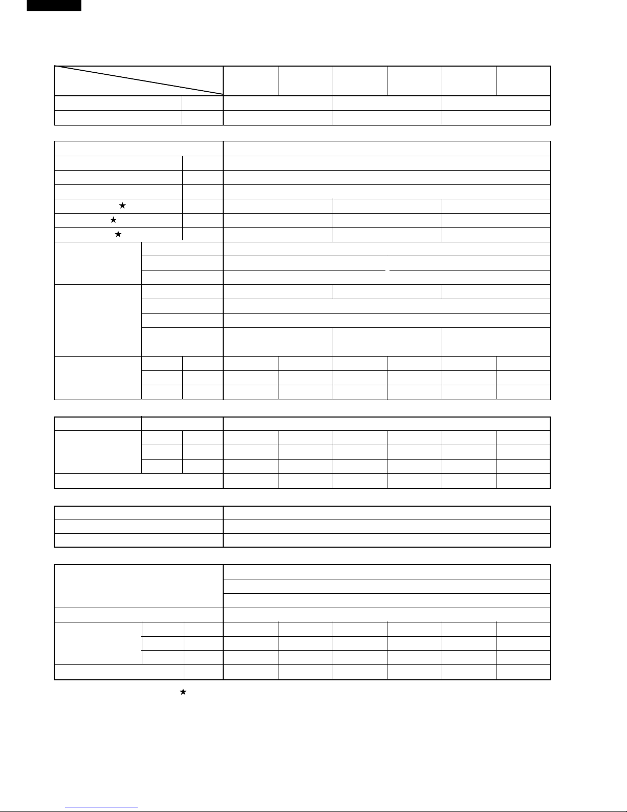
SPECIFICATIONS
MODEL
I
NDOOR UNIT
OUTDOOR UNIT
INDOOR UNIT
OUTDOOR UNIT
INDOOR UNIT
OUTDOOR UNIT
ITEMS AH-X08CR AU-X08CR AH-X10CR AU-X10CR AH-X13CR AU-X13CR
Cooling capacity
(Min. ~ Max.)
kW 2.2(0.9 _ 2.7) 2.8(0.9 _ 3.3) 3.6(0.9 _ 4.0)
Moisture removal Liters/h 0.6 0.7 1.3
Electrical data
Phase Single
Rated frequency Hz 50
Rated voltage range V 198 to 264
Rated voltage V 220 - 240
Rated current A 3.4 _ 3.1 4.3 _ 4.0 5.5 _ 5.1
Rated input W 730 930 1200
Power factor % 98 _ 98 98
_
97 99 _ 98
Type Hermetically sealed rotary type
Compressor Model DA89X1F-20F
Oil charge Ester oil VG68 370ml
Evaporator Bare tube type Grooved tube type Grooved tube type
Refrigerant system Condenser Louver Fin and Grooved tube type
Control Capillary tube
Refrigerant volume
640g 690g 660g
(R-410A)
Noise level
High dB(A) 33 43 36 43 38 48
(at cooling)
Med. dB(A) 29 – 32 – 33 Low dB(A) 27 – 27 – 29 -
Fan system
Drive Direct drive
Air flow quantity High m3/min. 7.5 28 8.7 28 9.3 30
(at cooling) Med. m3/min. 6.8 – 7.8 – 8.1 –
Low m3/min. 6.0 – 6.0 – 6.6 –
Fan
Cross flow fan Propeller fan Cross flow fan Propeller fan Cross flow fan Propeller fan
Connections
Refrigerant coupling Flare type
Refrigerant tube size Gas, Liquid 3/8", 1/4"
Drain piping mm O.D ø 18
Others
Compressor: Compressor thermistor
Safety device Fan motors: Thermal fuse
Fuse, Micro computer control
Air filters Polypropylene net (Washable)
Width mm 815 780 815 780 815 780
Net dimensions Height mm 278 540 278 540 278 540
Depth mm 198 269 198 269 198 269
Net weight kg 9 30 9 30 10 33
Note: The condition of star " " marked item are ‘ISO5151’ : 1994(E), condition T1.
Page 3
3
AH/AY-X08CR
AH/AY-X10CR
AH/AY-X13CR
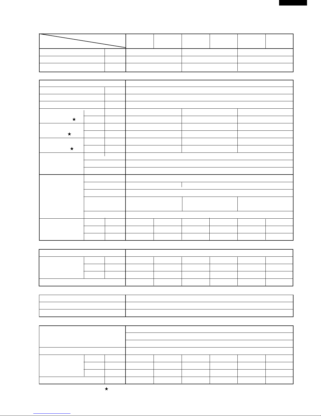
MODEL
I
NDOOR UNIT
OUTDOOR UNIT
INDOOR UNIT
OUTDOOR UNIT
INDOOR UNIT
OUTDOOR UNIT
ITEMS AY-X08CR AE-X08CR AY-X10CR AE-X10CR AY-X13CR AE-X13CR
Cooling capacity
(Min. ~ Max.)
kW 2.2(0.9 _ 2.7) 2.8(0.9 _ 3.3) 3.6(0.9 _ 4.0)
Heating capacity
(Min. ~ Max.)
kW 3.2(0.9 _ 3.6) 3.7(0.9 _ 5.0) 4.8(1.0 _ 6.2)
Moisture removal(at cooling) Liters/h 0.7 0.8 1.3
Electrical data
Phase Single
Rated frequency Hz 50
Rated voltage range V 198 to 264
Rated voltage V 220 - 240
Cool A 3.4 _ 3.1 4.3 _ 4.0 5.5 _ 5.1
Rated current Heat A 4.2 _ 3.9 4.9 _ 4.5 6.8 _ 6.2
Cool W 730 930 1200
Rated input Heat W 910 1050 1480
Cool % 98 _ 98 98 _ 97 99 _ 98
Power factor Heat % 98 _ 97 97 _ 97 99 _ 99
Type Hermetically sealed rotary type
Compressor Model DA89X1F-20F
Oil charge Ester oil VG68 370ml
Evaporator Louver Fin and Grooved tube type
Refrigerant system Condenser Corrugate Fin and Grooved tube type
Control Capillary tube
Refrigerant volume
750g 770g 870g
(R-410A)
De-lce system Micro computer controled reversed systems
Noise level
High dB(A) 33 43 36 43 38 48
(at cooling)
Med. dB(A) 29 – 32 – 33 Low dB(A) 27 – 27 – 29 -
Fan system
Drive Direct drive
Air flow quantity High m3/min. 7.5 28 9.8 27.7 9.3 30
(at cooling) Med. m3/min. 6.8 – 8.2 – 8.1 –
Low m3/min. 6.0 – 6.1 – 6.6 –
Fan
Cross flow fan Propeller fan Cross flow fan Propeller fan Cross flow fan Propeller fan
Connections
Refrigerant coupling Flare type
Refrigerant tube size Gas, Liquid 3/8", 1/4"
Drain piping mm O.D ø 18
Others
Compressor: Compressor thermistor
Safety device Fan motors: Thermal fuse
Fuse, Micro computer control
Air filters Polypropylene net (Washable)
Width mm 815 780 815 780 815 780
Net dimensions Height mm 278 540 278 540 278 540
Depth mm 198 269 198 269 198 269
Net weight kg 9 33 10 33 10 37
Note: The condition of star " " marked item are ‘ISO5151’ : 1994(E), condition T1.
Page 4
4
AH/AY-X08CR
AH/AY-X10CR
AH/AY-X13CR
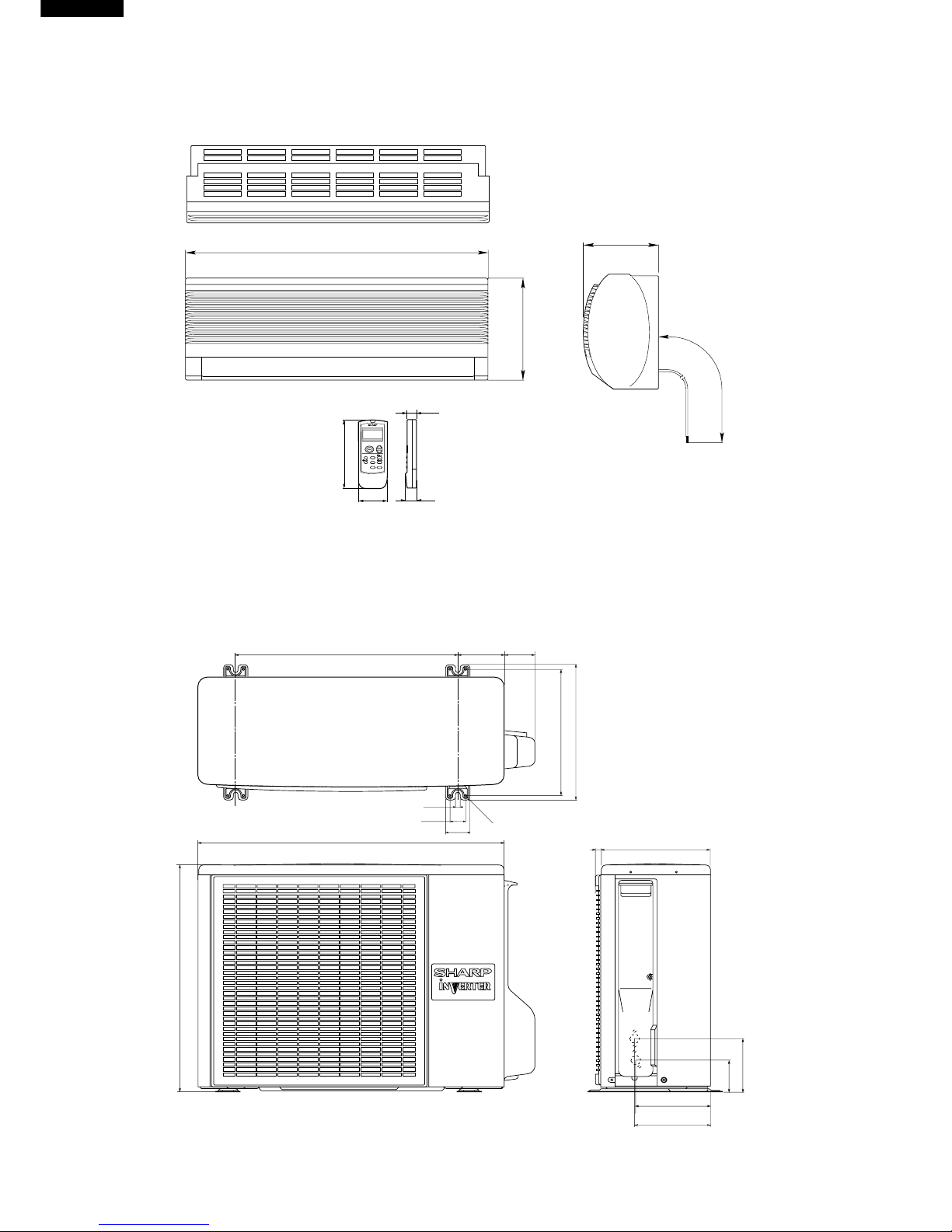
EXTERNAL DIMENSIONS
Figure E-1. INDOOR UNIT
Figure E-2. OUTDOOR UNIT
Length unit (mm)
815
278
198
1100
Remote controller
58
18.5
22
140
INVERTER AIR CONDITIONER
269
179.5
182.5
136
81
780
70
540
310
335
540
12
37.5
4.5
58
158
16
Page 5
5
AH/AY-X08CR
AH/AY-X10CR
AH/AY-X13CR
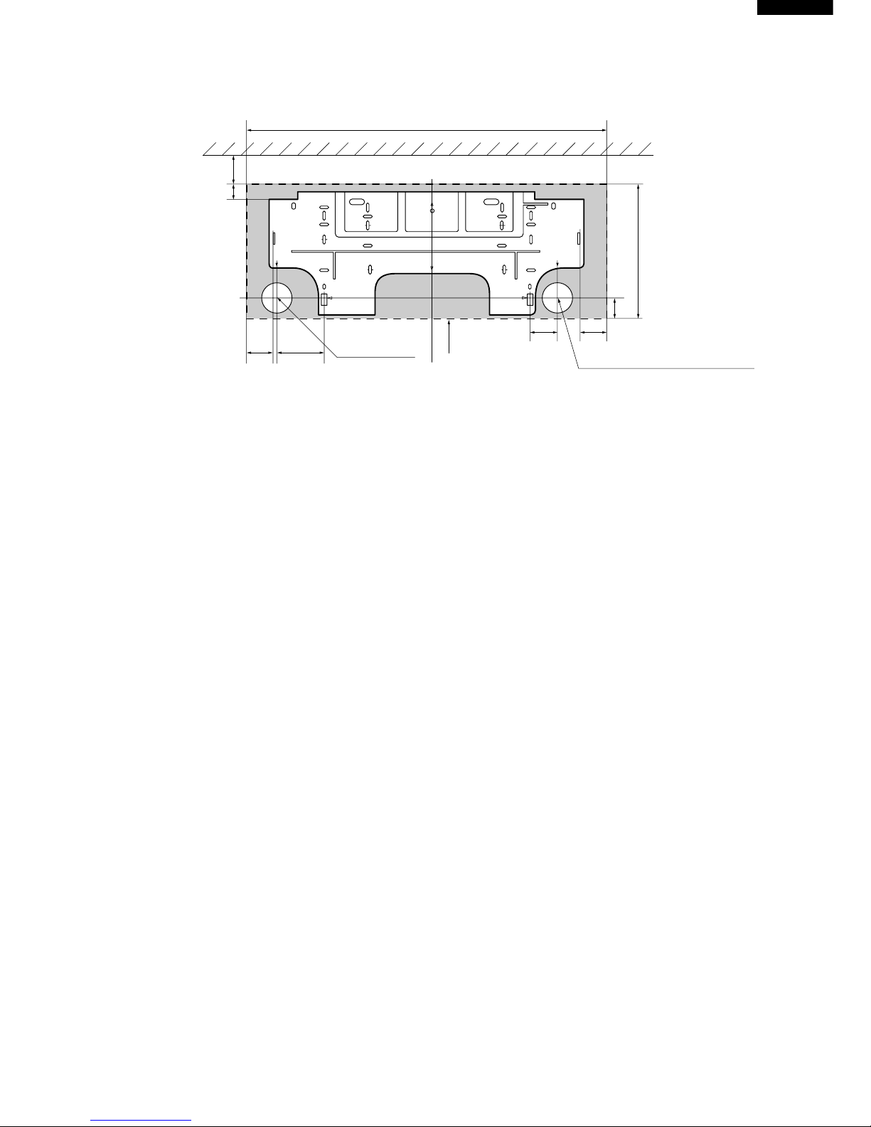
Figure E-3. INSTALLATION DIMENSIONS
815 (unit size)
More than 50mm
E
Center of wall hole:
Leftward piping
Center of wall hole: Backward piping
Outline of indoor unit
55 95
80 55
AJ
IF
E
D
D
FA
C
J
H
I
GB
21
278 (unit size)
38
Ceiling
E
Page 6

6
AH/AY-X08CR
AH/AY-X10CR
AH/AY-X13CR
WIRING DIAGRAMS
Figure W-1. Wiring Diagram for AH-X08CR/X10CR/X13CR and AY-X08CR/X10CR/X13CR
BROWN
RY1
In Out
CB612-1
10
7
8
6
Temperature
Indicator
Blinking No.
Abnormal contents
AC overcurrent
Abnormal AC current
WPE1
250V
3A
INDOOR UNIT
UNIT
TO
UNIT
CORD
Power factor module(AF1) error
13
Overheat of the power module(IPM) or
short circuit of the power module(IPM) heat-sink thermistor
Open circuit of the power module(IPM) heat-sink thermistor
Rotation error of the compressor
OUTDOOR UNIT
N
1
2
TERMINAL BOARD
CONTROL BOARD UNIT
POWER
SUPPLY
TERMINAL BOARD 2
SINGLE
PHASE
N
1
2
CONTROL
BOARD
UNIT
M
M
FAN MOTOR
COMPRESSOR
N
1
TERMINAL BOARD 1
M
M
LOUVER
(LOWER)
SERIAL
SIGNAL
CIRCUIT
BLUE
BLUE
BLACK
S
RED
N
INTERNAL
THERMAL
FUSE
RECEIVER
BOARD UNIT
R.P.M.
SIGNAL
FAN MOTOR
CAPACITOR
430V 2.0µF
FAN MOTOR
LOUVER
(UPPER)
13
TH1
5
CN1
BCN1
BCN3
BCN2
CN2
CN3
TH2
YELLOW
ORANGE
CN6
CN7
DISPLAY
BOARD
UNIT
CN101
CN102
ROOM TEMP.
THERMISTOR
PIPE TEMP.
THERMISTOR
GREEN-YELLOW
TRANS1
SSR1
1
3
4
2
RED
BLUE
BLACK
C1
LED INDICATION FOR SELF-DIAGNOSIS
5
2
3
1
14
17
18
19
Short circuit of the outdoor thermistor
Overheat of the compressor
Open circuit of the outdoor thermistor
Power module(IPM) abnormality
Open circuit of serial signal line
Abnormal fan motor of indoor unit
Short circuit of serial signal line
CB612-2
<Indication of the abnormal condition>
LED indicator will blink,if the set
is in abnormal condition.
Page 7

7
AH/AY-X08CR
AH/AY-X10CR
AH/AY-X13CR
Figure W-2. Wiring Diagram for AE-X08CR/X10CR
+
-
+
-
N
1
2
INDOOR UNIT
TERMINAL
BOARD
CONTROL
BOARD
UNIT
POWER
SUPPLY
FAN
MOTOR
TERMINAL BOARD
UNIT TO UNIT CORD
SINGLE PHASE
220-240V 50Hz
BL
T2
BR
T3
RE
FC4
BULK HEAD
RE
T1
WPE1
C1
C2
C3
C4
C33
C34
15A
250V
SA1
RY1
T4
BCN11
CT1
The voltage is high at C8 (electronic capacitors) on outdoor unit.
For mentenance discharge at C8 to prevent electric shock.
In case that WPE101 has been fused, the voltage is kept high at C8.
CAUTION
BK
:
BLACK RE
:
RED YE
:
YELLOW
BL
:
BLUE WH
:
WHITE G:GREEN
BR
:
BROWN OR
:
ORANGE
GR
:
GRAY G
(
Y
):
GREEN-YELLOW
BL
GR
G
(
Y
)
G
(
Y
)
FAN
MOTOR
BL
PTC
MRY1
IN OUT
T6
T5
BK
TP
TN
YE
C8
OUTDOOR UNIT
POWER
TRANSISTOR
MODULE
(
QM101
)
TU TV TW
RE
WH
OR
COMPRESSOR
THERMISTOR
PIPE TEMP.
THERMISTOR
OUTDOOR
TEMP.
THERMISTOR
COMP. TEMP.
CN8
TH2
TH1
TH3
RE
OR
G
3
1
5
LED INDICATION OF SELF-DIAGNOSIS
ON OUTDOOR UNIT
LED BLINKING
LED turns on
Slow flashing
(
1 time for 2 seconds
)
Quick flashing
(
3 times for 2 seconds
)
Example: NO.2 Overheat of the compressor
1.0sec 0.6sec 0.6sec 1.0sec 0.6sec 0.6sec
CB565
123
4
10
NO. LED indication pattern
Mulfunction part or abnormal condition
Normal
Abnormal signal line
Overheat of the compressor
DC overcurrent of the power module
(
QM101
)
Short circuit of the thermistor
7
8
6
NO. LED indication pattern
Mulfunction part or abnormal condition
Open circuit of the thermistor
AC overcurrent
AC abnormal current
BK
1
2
3
4
5
6
NR1
NR2
CNR1
N
1
2
L3
L4
WPE33A250V
CN3
CONTROL BOARD UNIT
DIODE BRIDGE
DB1
BL
C5
WPE101
20A
250V
OR
FC1
C10
C
AM
CONTROL
BOX
FAN MOTOR
CAPACITOR
1.5µF 450V
C31
+
-
L1
WH
C8:1000µF 420V
BL
~
~
9
Power factor module(AF1) error
S
R
C(T)
FC5
AF1
LL+
I-
I+
ACTIVE
FILTER
O-
O+
WH
YE
BR
FC2
3
1
RY2
CNR2
4-WAY
VALVE
5
11
Overheat of the power module or
short circuit of the heat-sink thermistor
Open circuit of the heat-sink thermistor
Rotation error of the compressor
C36
C35
C37
C38
BK
1
3
THERMISTOR
HEAT-SINK
TEMP.
CN7
41
YE
BL
CN12
CN13
BCN2
CN101
CN102
CN6
2
4
6
RE
WH
OR
POWER
TRANSISTOR
UNIT
NO.3 DC overcurrent of the power module
(
QM101
)
1.0sec 0.6sec 0.6sec 1.0sec 0.6sec
0.6sec
0.6sec
0.6sec
x 2times
x 3times
x 4times
x 5times
x 6times
x 7times
x 9times
x 11times
x 13times
x 14times
This circuit
is removed
about cooling
only models
CN4
Page 8

8
AH/AY-X08CR
AH/AY-X10CR
AH/AY-X13CR
Figure W-3. Wiring Diagram for AE-X13CR
+
-
+
-
N
1
2
INDOOR UNIT
TERMINAL
BOARD
CONTROL
BOARD
UNIT
POWER
SUPPLY
FAN
MOTOR
TERMINAL BOARD
UNIT TO UNIT CORD
SINGLE PHASE
220-240V 50Hz
BL
T2
BR
T3
RE
FC4
BULK HEAD
RE
T1
WPE1
C1
C2
C3
C4
C33
C34
20A
250V
SA1
RY1
T4
BCN11
CT1
The voltage is high at C8 (electronic capacitors) on outdoor unit.
For mentenance discharge at C8 to prevent electric shock.
In case that WPE101 has been fused, the voltage is kept high at C8.
CAUTION
BK
:
BLACK RE
:
RED YE
:
YELLOW
BL
:
BLUE WH
:
WHITE G:GREEN
BR
:
BROWN OR
:
ORANGE
GR
:
GRAY G
(
Y
):
GREEN-YELLOW
BL
GR
G
(
Y
)
G
(
Y
)
FAN
MOTOR
BL
PTC
MRY1
IN OUT
T6
T5
BK
TP
TN
YE
C8
OUTDOOR UNIT
POWER
TRANSISTOR
MODULE
(
QM101
)
TU TV TW
RE
WH
OR
COMPRESSOR
THERMISTOR
PIPE TEMP.
THERMISTOR
OUTDOOR
TEMP.
THERMISTOR
COMP. TEMP.
CN8
TH2
TH1
TH3
RE
OR
G
3
1
5
LED INDICATION OF SELF-DIAGNOSIS
ON OUTDOOR UNIT
LED BLINKING
LED turns on
Slow flashing
(
1 time for 2 seconds
)
Quick flashing
(
3 times for 2 seconds
)
Example: NO.2 Overheat of the compressor
1.0sec 0.6sec 0.6sec 1.0sec 0.6sec 0.6sec
CB566
123
4
10
NO. LED indication pattern
Mulfunction part or abnormal condition
Normal
Abnormal signal line
Overheat of the compressor
DC overcurrent of the power module
(
QM101
)
Short circuit of the thermistor
7
8
6
NO. LED indication pattern
Mulfunction part or abnormal condition
Open circuit of the thermistor
AC overcurrent
AC abnormal current
BK
1
2
3
4
5
6
NR1
NR2
CNR1
N
1
2
L3
L4
WPE33A250V
CN3
CONTROL BOARD UNIT
DIODE BRIDGE
DB1
BL
C5
WPE101
20A
250V
OR
FC1
C10
C
AM
CONTROL
BOX
FAN MOTOR
CAPACITOR
2.0µF 450V
C31
+
-
L1
WH
C8:1300
µ
F 420V
BL
~
~
9
Power factor module(AF1) error
S
R
C(T)
FC5
AF1
L
-
L
+
I
-
I
+
ACTIVE
FILTER
O
-
O
+
WH
YE
BR
FC2
3
1
RY2
CNR2
4-WAY
VALVE
5
11
Overheat of the power module or
short circuit of the heat-sink thermistor
Open circuit of the heat-sink thermistor
Rotation error of the compressor
C36
C35
C37
C38
BK
1
3
THERMISTOR
HEAT-SINK
TEMP.
CN7
41
YE
BL
CN12
CN13
BCN2
CN101
CN102
CN6
2
4
6
RE
WH
OR
POWER
TRANSISTOR
UNIT
NO.3 DC overcurrent of the power module
(
QM101
)
1.0sec 0.6sec 0.6sec 1.0sec 0.6sec
0.6sec
0.6sec
0.6sec
x 2times
x 3times
x 4times
x 5times
x 6times
x 7times
x 9times
x 11times
x 13times
x 14times
This circuit
is removed
about cooling
only models
CN4
Page 9

9
AH/AY-X08CR
AH/AY-X10CR
AH/AY-X13CR
Figure W-4. Wiring Diagram for AU-X08CR/X10CR
+
-
+
-
N
1
2
INDOOR UNIT
TERMINAL
BOARD
CONTROL
BOARD
UNIT
POWER
SUPPLY
FAN
MOTOR
TERMINAL BOARD
UNIT TO UNIT CORD
SINGLE PHASE
220-240V 50Hz
BL
T2
BR
T3
RE
FC4
BULK HEAD
RE
T1
WPE1
C1
C2
C3
C4
C33
C34
15A
250V
SA1
RY1
T4
BCN11
CT1
The voltage is high at C8 (electronic capacitors) on outdoor unit.
For mentenance discharge at C8 to prevent electric shock.
In case that WPE101 has been fused, the voltage is kept high at C8.
CAUTION
BK
:
BLACK RE
:
RED YE
:
YELLOW
BL
:
BLUE WH
:
WHITE G:GREEN
BR
:
BROWN OR
:
ORANGE
GR
:
GRAY G
(
Y
):
GREEN-YELLOW
BL
GR
G
(
Y
)
G
(
Y
)
FAN
MOTOR
BL
PTC
MRY1
IN OUT
T6
T5
BK
TP
TN
YE
C8
OUTDOOR UNIT
POWER
TRANSISTOR
MODULE
(
QM101
)
TU TV TW
RE
WH
OR
COMPRESSOR
THERMISTOR
PIPE TEMP.
THERMISTOR
OUTDOOR
TEMP.
THERMISTOR
COMP. TEMP.
CN8
TH2
TH1
TH3
RE
OR
G
3
1
5
LED INDICATION OF SELF-DIAGNOSIS
ON OUTDOOR UNIT
LED BLINKING
LED turns on
Slow flashing
(
1 time for 2 seconds
)
Quick flashing
(
3 times for 2 seconds
)
Example: NO.2 Overheat of the compressor
1.0sec 0.6sec 0.6sec 1.0sec 0.6sec 0.6sec
CB567
123
4
10
NO. LED indication pattern
Mulfunction part or abnormal condition
Normal
Abnormal signal line
Overheat of the compressor
DC overcurrent of the power module
(
QM101
)
Short circuit of the thermistor
7
8
6
NO. LED indication pattern
Mulfunction part or abnormal condition
Open circuit of the thermistor
AC overcurrent
AC abnormal current
BK
1
2
3
4
5
6
NR1
NR2
CNR1
N
1
2
L3
L4
WPE33A250V
CN3
CONTROL BOARD UNIT
DIODE BRIDGE
DB1
BL
C5
WPE101
20A
250V
OR
FC1
C10
C
AM
CONTROL
BOX
FAN MOTOR
CAPACITOR
1.5µF 450V
C31
+
-
L1
WH
C8:1000
µF 420V
BL
~
~
9
Power factor module(AF1) error
S
R
C(T)
FC5
AF1
L
-
L
+
I
-
I
+
ACTIVE
FILTER
O
-
O
+
WH
YE
BR
FC2
5
11
Overheat of the power module or
short circuit of the heat-sink thermistor
Open circuit of the heat-sink thermistor
Rotation error of the compressor
C36
C35
C37
C38
BK
1
3
THERMISTOR
HEAT-SINK
TEMP.
CN7
41
YE
BL
CN12
CN13
BCN2
CN101
CN102
CN6
2
4
6
RE
WH
OR
POWER
TRANSISTOR
UNIT
NO.3 DC overcurrent of the power module
(
QM101
)
1.0sec 0.6sec 0.6sec 1.0sec 0.6sec
0.6sec
0.6sec
0.6sec
x 2times
x 3times
x 4times
x 5times
x 6times
x 7times
x 9times
x 11times
x 13times
x 14times
Page 10

10
AH/AY-X08CR
AH/AY-X10CR
AH/AY-X13CR
Figure W-5. Wiring Diagram for AU-X13CR
+
-
+
-
N
1
2
INDOOR UNIT
TERMINAL
BOARD
CONTROL
BOARD
UNIT
POWER
SUPPLY
FAN
MOTOR
TERMINAL BOARD
UNIT TO UNIT CORD
SINGLE PHASE
220-240V 50Hz
BL
T2
BR
T3
RE
FC4
BULK HEAD
RE
T1
WPE1
C1
C2
C3
C4
C33
C34
20A
250V
SA1
RY1
T4
BCN11
CT1
The voltage is high at C8 (electronic capacitors) on outdoor unit.
For mentenance discharge at C8 to prevent electric shock.
In case that WPE101 has been fused, the voltage is kept high at C8.
CAUTION
BK
:
BLACK RE
:
RED YE
:
YELLOW
BL
:
BLUE WH
:
WHITE G:GREEN
BR
:
BROWN OR
:
ORANGE
GR
:
GRAY G
(
Y
):
GREEN-YELLOW
BL
GR
G
(
Y
)
G
(
Y
)
FAN
MOTOR
BL
PTC
MRY1
IN OUT
T6
T5
BK
TP
TN
YE
C8
OUTDOOR UNIT
POWER
TRANSISTOR
MODULE
(
QM101
)
TU TV TW
RE
WH
OR
COMPRESSOR
THERMISTOR
PIPE TEMP.
THERMISTOR
OUTDOOR
TEMP.
THERMISTOR
COMP. TEMP.
CN8
TH2
TH1
TH3
RE
OR
G
3
1
5
LED INDICATION OF SELF-DIAGNOSIS
ON OUTDOOR UNIT
LED BLINKING
LED turns on
Slow flashing
(
1 time for 2 seconds
)
Quick flashing
(
3 times for 2 seconds
)
Example: NO.2 Overheat of the compressor
1.0sec 0.6sec 0.6sec 1.0sec 0.6sec 0.6sec
CB568
123
4
10
NO. LED indication pattern
Mulfunction part or abnormal condition
Normal
Abnormal signal line
Overheat of the compressor
DC overcurrent of the power module
(
QM101
)
Short circuit of the thermistor
7
8
6
NO. LED indication pattern
Mulfunction part or abnormal condition
Open circuit of the thermistor
AC overcurrent
AC abnormal current
BK
1
2
3
4
5
6
NR1
NR2
CNR1
N
1
2
L3
L4
WPE33A250V
CN3
CONTROL BOARD UNIT
DIODE BRIDGE
DB1
BL
C5
WPE101
20A
250V
OR
FC1
C10
C
AM
CONTROL
BOX
FAN MOTOR
CAPACITOR
2.0µF 430V
C31
+
-
L1
WH
C8:1300
µ
F 420V
BL
~
~
9
Power factor module(AF1) error
S
R
C(T)
FC5
AF1
L
-
L
+
I
-
I
+
ACTIVE
FILTER
O
-
O
+
WH
YE
BR
FC2
5
11
Overheat of the power module or
short circuit of the heat-sink thermistor
Open circuit of the heat-sink thermistor
Rotation error of the compressor
C36
C35
C37
C38
BK
1
3
THERMISTOR
HEAT-SINK
TEMP.
CN7
41
YE
BL
CN12
CN13
BCN2
CN101
CN102
CN6
2
4
6
RE
WH
OR
POWER
TRANSISTOR
UNIT
NO.3 DC overcurrent of the power module
(
QM101
)
1.0sec 0.6sec 0.6sec 1.0sec 0.6sec
0.6sec
0.6sec
0.6sec
x 2times
x 3times
x 4times
x 5times
x 6times
x 7times
x 9times
x 11times
x 13times
x 14times
Page 11

27
AH/AY-X08CR
AH/AY-X10CR
AH/AY-X13CR
BREAK DOWN DIAGNOSIS PROCEDURE
Self-diagnostic procedure using display mode
If the timer lamp blinks during operation, the problem can be diagnosed using the following table.
: Blinks at 2-second intervals : OFF : ON : Blinks 3 times at 0.2-second intervals
The error of outdoor unit
Display by indoor unit operation lamp
Displayed in a pattern which comes on at the same
time as the timer lamp
4 seconds off
What to check, procedure
Display by
outdoor
unit lamp
LED 1
Diagnosis
Solution
Condition
of indoor
and
outdoor
unit
Normal
Twice
3 times
4 times
5 times
6 times
7 times
DC overcurrent error
AC overcurrent error
Normal
Overheat of the power
module or short circuit
of the heatsink
thermistor.
1. Check the circuit in the power transistor module.
2. Is the outdoor fan revolving ?
1. Is the discharge outlet of the outdoor unit clogged ?
1. Measure the resistance of heatsink thermistor TH6 on the heatsink
in outdoor unit.
2. Check rotation of the fan motor in outdoor unit.
3. Is the power supply voltage at least 198V at full power operation ?
1. Measure the resistance of thermistor TH2 on the outdoor unit
(see Figure 3).
1. Replace power transistor
module
1. Clear the discharge outlet.
11 times Power factor module error
1. CHeck wiring of power factor module.
1. Replace the power factor module.
1. Reattach.
2. Reattach CN101 and CN102,
otherwise replace power transistor
module assembly or outdoor control
board assembly.
9 times
14 times
13 times
Rotation errot of the
compressor
1. Has not if escaped from the compressor CN6 ?
2. Is the power supplied of 15V and 6V supplied to the IPM PWB.
1. Replace the heatsink thermistor.
Open circuit of the
heatsink thermistor.
1. Are the connectors of the heatsink thermistor in outdoor unit well
attached ?
2. Measure the resistance of thermistor TH6 on the heatsink.
(See Figure 3).
Overheat of the comp-
ressor error
(protector operating) or
outdoor compressor
thermistor TH1 short
1. Reattach.
2. Replace the heatsink thermistor.
1. Replace the outdoor control board
assembly
(Current transformer wire break.)
1. Reattach.
2. Replace the outdoor thermistor
assembly.
1. Replace the outdoor thermistor
assembly.
1. Clear the discharge outlet.
2. Assure power supply voltage.
3. Refill to rated amount.
4. Replace the outdoor ther-mistor
assembly.
5. Replace the indoor control board
assembly or only TH2.
1. Can voltage be detected at the current transformer on the outdoor
unit control board?
1. Is the connector of the outdoor unit thermistors well attached ?
(see Figure 3).
2. Measure the resistance of thermistors TH1 and TH2 on the
outdoor unit (see Figure 3).
1. Is the discharge outlet of the outdoor unit clogged ?
2. Is the power supply voltage at least 198 V at full power operation ?
3. Check for refrigerant leaks at the tubing connections.
4. Measure the resistance of compressor thermistor TH1 on the
outdoor unit (see Figure 3).
5. Measure the resistance of heat exchanger pipe thermistor TH2 on
the indoor unit (see Figure 1).
AC abnormal current
error
Open circuit of the
outdoor thermistor error
Short circuit of the
outdoor thermistor error
2. Reattach CN3, otherwise replace
the fan motor of outdoor unit.
3. Assure power supply voltage.
Page 12

28
AH/AY-X08CR
AH/AY-X10CR
AH/AY-X13CR
Note: 1. Normal : Only the timer lamp blinks. Error : Displayed by blinking of run
lamp (above table).
2. If the power plug is removed from the outlet or the breaker is switched to
"OFF", the self-diagnostic memory will be erased.
3. Example of outdoor unit LED 1 blinking :
: Blinks at 2-second intervals : OFF : ON : Blinks 3 times at 0.2-second intervals
The error of indoor unit
Display by indoor unit operation lamp
Displayed in a pattern which comes on at the same
time as the timer lamp
4 seconds off
What to check, procedure
Display by
outdoor
unit lamp
LED 1
Diagnosis
Solution
Condition
of indoor
and
outdoor
unit
Serial short
Serial open
1. Check the wiring between units.
1. Check the wiring between units.
1. Check the wiring between units.
2. Check the fuse in the outdoor unit.
3. Indoor control board.
4. Outdoor control board.
1. Rewire.
1. Rewire.
Indoor fan out of order
1. Is the fan motor locked ?
2. Is the wiring connector firmly fitted ?
3. Is the speed signal applied to the motor ?
Outdoor power supply
does't turn on.
Wiring mistake.
1. Rewire.
2. Replace the fuse, replace the
outdoor board assembly.
3. Replace the board.
4. Replace the board.
1. Replace fan motor
2. Reattach.
3. Replace the indoor control board
assembly.
1
sec.
1
sec.
0.6
sec.
1
sec.
1
sec.
1
sec.
1
sec.
1
sec.
1
sec.
Overheat of the compressor
0.6
sec.
1
sec.
0.6
sec.
1
sec.
0.6
sec.
2 times
OFFONOFF
Page 13

32
AH/AY-X08CR
AH/AY-X10CR
AH/AY-X13CR
PERFORMANCE CURVES
NOTE: 1) Indoor fan speed: Hi
2) Vertical adjustment louver "45˚", Horizontal adjustment louver "front"
3) Indoor air temp. : Cooling 27˚C, Heating 20˚C
Figure P-1. At Cooling for AH-X08CR
Figure P-2. At Cooling for AH-X10CR
Figure P-3. At Cooling for AH-X13CR Figure P-4. At Cooling for AY-X08CR
Figure P-5. At Cooling for AY-X10CR
Figure P-6. At Cooling for AY-X13CR
25 30 35 40
2.0
2.2
2.4
2.6
10
12
14
600
700
800
900
Cooling capacity(kW)
Outside air temp.(˚C)
Input(W)
Outlet air temp.(˚C)
(Running frequency: 50HZ)
25 30 35 40
2.4
2.6
2.8
3.0
3.2
12
14
16
700
800
900
1000
(Running frequency: 62Hz)
Cooling capacity(kW)
Outside air temp.(˚C)
Input(W)
Outlet air temp.(˚C)
25 30 35 40
3.2
3.4
3.6
3.8
4.0
10
12
14
1000
1100
1200
1300
(Running frequency: 81Hz)
Cooling capacity(kW)
Outside air temp.(˚C)
Input(W)
Outlet air temp.(˚C)
25 30 35 40
2.0
2.2
2.4
2.6
10
12
14
600
700
800
900
Cooling capacity(kW)
Outside air temp.(˚C)
Input(W)
Outlet air temp.(˚C)
(Running frequency: 51Hz)
25 30 35 40
2.4
2.6
2.8
3.0
3.2
12
14
16
700
800
900
1000
(Running frequency: 63Hz)
Cooling capacity(kW)
Outside air temp.(˚C)
Input(W)
Outlet air temp.(˚C)
25 30 35 40
3.2
3.4
3.6
3.8
4.0
10
12
14
1000
1100
1200
1300
(Running frequency: 83Hz)
Cooling capacity(kW)
Outside air temp.(˚C)
Input(W)
Outlet air temp.(˚C)
Page 14

33
AH/AY-X08CR
AH/AY-X10CR
AH/AY-X13CR
Figure P-7. At Heating for AY-X08CR Figure P-8. At Heating for AY-X10CR
Figure P-9. At Heating for AY-X13CR
-5 0 7510
2.4
2.8
3.2
3.6
35
40
45
700
800
900
1000
(Running frequency: 68Hz)
Heating capacity(kW)
Outside air temp.(˚C)
Input(W)
Outlet air temp.(˚C)
-5 0 5 7 10
2.5
3.0
3.5
4.0
30
35
40
45
800
900
1000
1100
(Running frequency: 79Hz)
Heating capacity(kW)
Outside air temp.(˚C)
Input(W)
Outlet air temp.(˚C)
-5 0 5 7 10
3.0
3.5
4.0
4.5
5.0
5.5
30
35
40
45
1200
1300
1400
1500
1600
(Running frequency: 96Hz)
Heating capacity(kW)
Outside air temp.(˚C)
Input(W)
Outlet air temp.(˚C)
 Loading...