

Page 1
AY-AP18CE AY-AP24CE
AH-AP18CE AH-AP24CE
AE-A18CE AE-A24CE
AU-A18CE AU-A24CE
1
INDOOR UNIT
AH-AP18CE AY-AP18CE
AH-AP24CE AY-AP24CE
OUTDOOR UNIT
MODELS
SERVICE MANUAL
S7222AYAP24CE
SHARP CORPORATION
In the interests of user-safety (Required by safety regulations in some
countries) the set should be restored to its original condition and only
parts identical to those specified should be used.
SPLIT SYSTEM
ROOM AIR CONDITIONERS
AU-A18CE AE-A18CE
AU-A24CE AE-A24CE
TABLE OF CONTENTS
Page
SPECIFICATIONS .............................................................................................................................................2
EXTERNAL DIMENSIONS ............................................................................................................................... 4
WIRING DIAGRAMS.........................................................................................................................................5
ELECTRICAL PARTS ....................................................................................................................................... 9
MICROCOMPUTER CONTROL SYSTEM .....................................................................................................11
FUNCTIONS ...................................................................................................................................................19
TROUBLESHOOTING GUIDE OF CONTROL CIRCUIT ................................................................................ 27
REFRIGERATION CYCLE ..............................................................................................................................32
PERFORMANCE CURVES ............................................................................................................................34
REFRIGERANT PIPE INSTALLATION WORKS .............................................................................................35
DISASSEMBLING PROCEDURE ................................................................................................................... 37
REPLACEMENT PARTS LIST ........................................................................................................................46
Page 2
AY-AP18CEAY-AP24CE
AH-AP18CEAH-AP24CE
AE-A18CE AE-A24CE
AU-A18CE AU-A24CE
2
ITEMS INDOOR UNIT OUTDOOR UNIT INDOOR UNIT OUTDOOR UNIT
AY-AP18CE AE-A18CE AY-AP24CE AE-A24CE
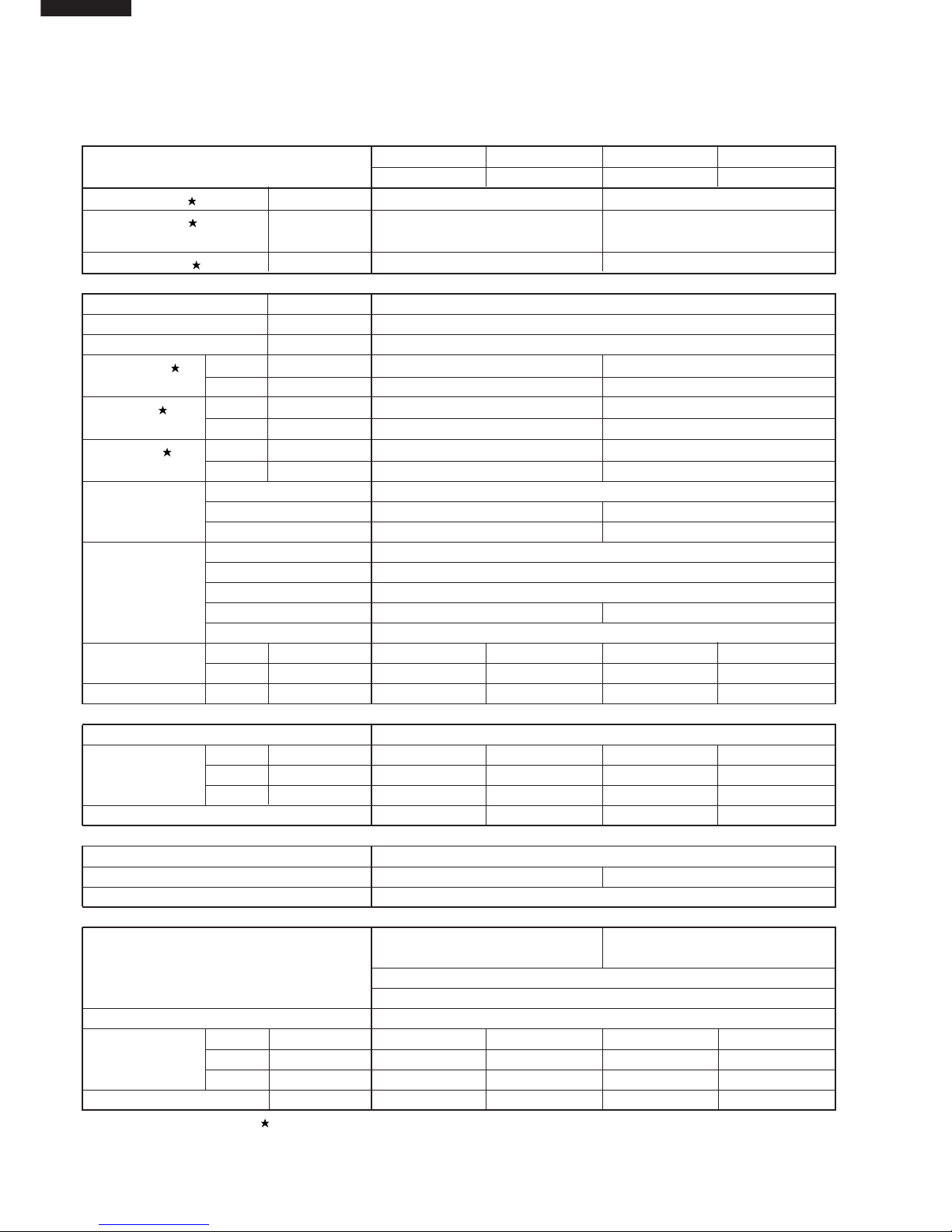
Cooling capacity kW 5.1 6.7
Heating capacity
kW 5.8 8.3
Moisture removal Liters/h 1.6 2.2
Electrical data
Phase – Single
Rated frequency Hz 50
Rated voltage V 220 – 240
Rated current Cool A 9.3 – 9.7 13.2 – 13.7
Heat A 9.2 – 9.8 13.6 – 14.3
Rated input Cool kW 2.01 – 2.15 2.68 – 2.84
Heat kW 1.95 – 2.10 2.76 – 2.97
Rated factor Cool % 98 – 92 92 – 86
Heat % 96 – 89 92 – 87
Compressor Type Hermetically sealed rotary type
Model PH33VPET 2JS464D3AA02
Oil charge 900cc [DIAMOND MS32(N-1)] 1130cc (
ATMOS M60 or SUNISO 4GD1D)
Refrigerant system Evaporator Louver fin and Grooved tube type
Condenser Corrgate fin and Grooved tube type
Control Capillary tube
Refrigerant volume 1380g 1770g
De-lce system Micro computer controled reverse sysetm
Noise level High dB(A) 40 52 44 54
(at cooling) Med. dB(A) 36 – 39 –
Low dB(A) 34 – 37 –
Fan system
Drive Direct drive
Air flow quantity High m3/min. 15.3 48 18.1 46
(at cooling) Med. m3/min. 13.4 – 15.0 –
Low m3/min. 11.3 – 13.7 –
Fan Cross flow fan Propeller fan Cross flow fan Propeller fan
Connections
Refrigerant coupling Flare type
Refrigerant tube size Gas, Liquid 1/2", 1/4" 5/8", 1/4"
Drain piping mm O.D ø 20
Others
Safety device Compressor: Internal protector Compressor: Internal protector
Fan motors: Thermal protector(Internal)
Fuse, Micro computer control
Air filters Polypropylene net (Washable)
Net dimensions Width mm 1040 (1155) 890 (1020) 1040 (1155) 890 (1020)
(Cartont dimensions)
Height mm 325 (300) 645 (735) 325 (300) 645 (735)
Depth mm 220 (385) 327 (398) 220 (385) 327 (398)
Net weight (Gross weight) kg 16 (21) 58 (62) 16 (21) 64 (68)
Note: The condition of star (
) marked item are ‘ISO5151:1994(E), condition T1’.
SPECIFICATIONS
Page 3
AY-AP18CE AY-AP24CE
AH-AP18CE AH-AP24CE
AE-A18CE AE-A24CE
AU-A18CE AU-A24CE
3
ITEMS INDOOR UNIT OUTDOOR UNIT INDOOR UNIT OUTDOOR UNIT
AH-AP18CE AU-A18CE AH-AP24CE AU-A24CE
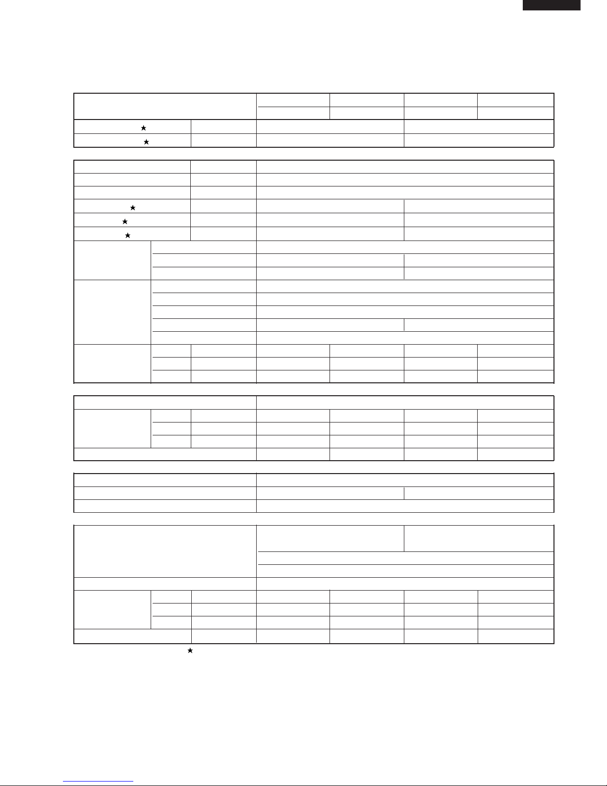
Cooling capacity kW 5.1 6.7
Moisture removal Liters/h 1.6 2.2
Electrical data
Phase – Single
Rated frequency Hz 50
Rated voltage V 220 – 240
Rated current A 9.3 – 9.7 13.2 – 13.7
Rated input kW 2.01 – 2.15 2.68 – 2.84
Rated factor % 98 – 92 92 – 86
Compressor Type Hermetically sealed rotary type
Model PH33VPET 2JS464D3AA02
Oil charge 900cc [DIAMOND MS32(N-1)] 1130cc (
ATMOS M60 or SUNISO 4GD1D)
Refrigerant system Evaporator Louver fin and Grooved tube type
Condenser Louver fin and Grooved tube type
Control Capillary tube
Refrigerant volume 960g 1320g
De-lce system Micro computer controled reverse sysetm
Noise level High dB(A) 40 52 44 54
(at cooling) Med. dB(A) 36 – 39 –
Low dB(A) 34 – 37 –
Fan system
Drive Direct drive
Air flow quantity High m3/min. 15.3 48 18.1 46
(at cooling) Med. m3/min. 13.4 – 15.0 –
Low m3/min. 11.3 – 13.7 –
Fan Cross flow fan Propeller fan Cross flow fan Propeller fan
Connections
Refrigerant coupling Flare type
Refrigerant tube size Gas, Liquid 1/2", 1/4" 5/8", 1/4"
Drain piping mm O.D ø 20
Others
Safety device Compressor: Internal protector Compressor: Internal protector
Fan motors: Thermal protector(Internal)
Fuse, Micro computer control
Air filters Polypropylene net (Washable)
Net dimensions Width mm 1040 (1155) 890 (1020) 1040 (1155) 890 (1020)
(Cartont dimensions)
Height mm 325 (300) 645 (735) 325 (300) 645 (735)
Depth mm 220 (385) 327 (398) 220 (385) 327 (398)
Net weight (Gross weight) kg 16 (21) 55 (59) 16 (21) 61 (65)
Note: The condition of star (
) marked item are ‘ISO5151:1994(E), condition T1’.
Page 4
AY-AP18CEAY-AP24CE
AH-AP18CEAH-AP24CE
AE-A18CE AE-A24CE
AU-A18CE AU-A24CE
4
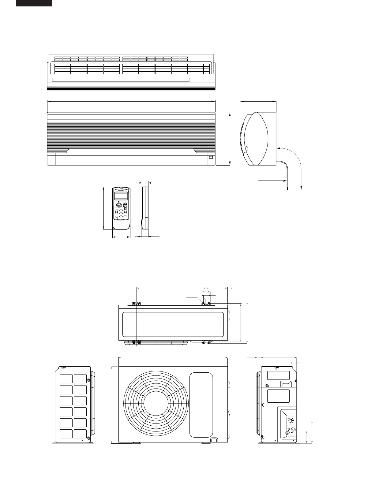
570
645
202
122
320
342
890 29037
30
172
25
62
46.3
10.5
ø4.5
220
950
Power supply cord
(AY-AP18CE, AH-AP18CE only)
[Length unit : mm]
325
1040
Remote controller
58
18.5
22
140
SAVE
MODE
TEMP.
FANIH
SWING
CANCELFULL POWER
INVERTER AIR CONDITIONER
TEMP.
MODE
FAN
TIMER
EXTERNAL DIMENSIONS
Figure E-1. INDOOR UNIT
Figure E-2. OUTDOOR UNIT
Page 5
AY-AP18CE AY-AP24CE
AH-AP18CE AH-AP24CE
AE-A18CE AE-A24CE
AU-A18CE AU-A24CE
5
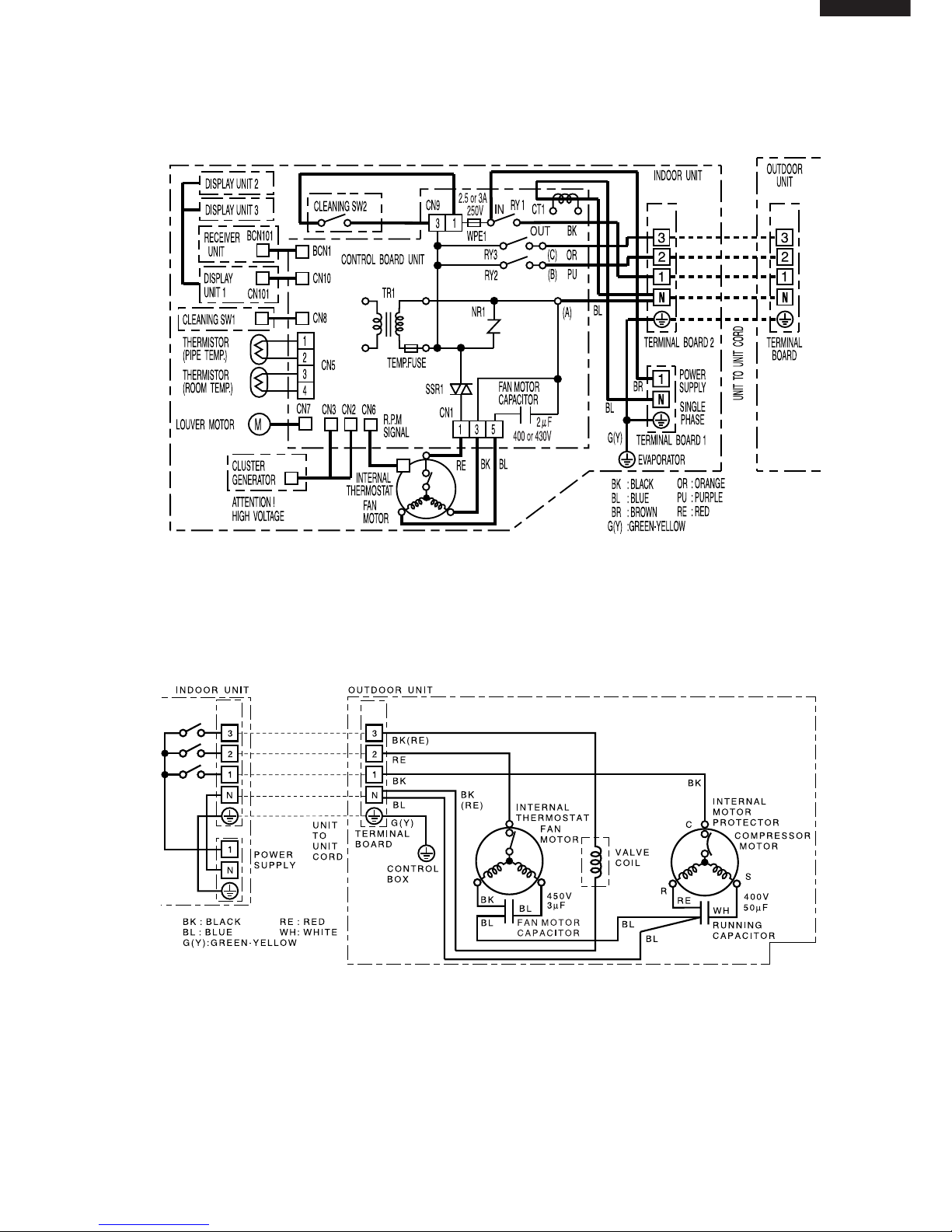
WIRING DIAGRAMS
Figure W-1. Wiring Diagram for AY-AP18CE
Figure W-2. Wiring Diagram for AE-A18CE
Page 6
AY-AP18CEAY-AP24CE
AH-AP18CEAH-AP24CE
AE-A18CE AE-A24CE
AU-A18CE AU-A24CE
6
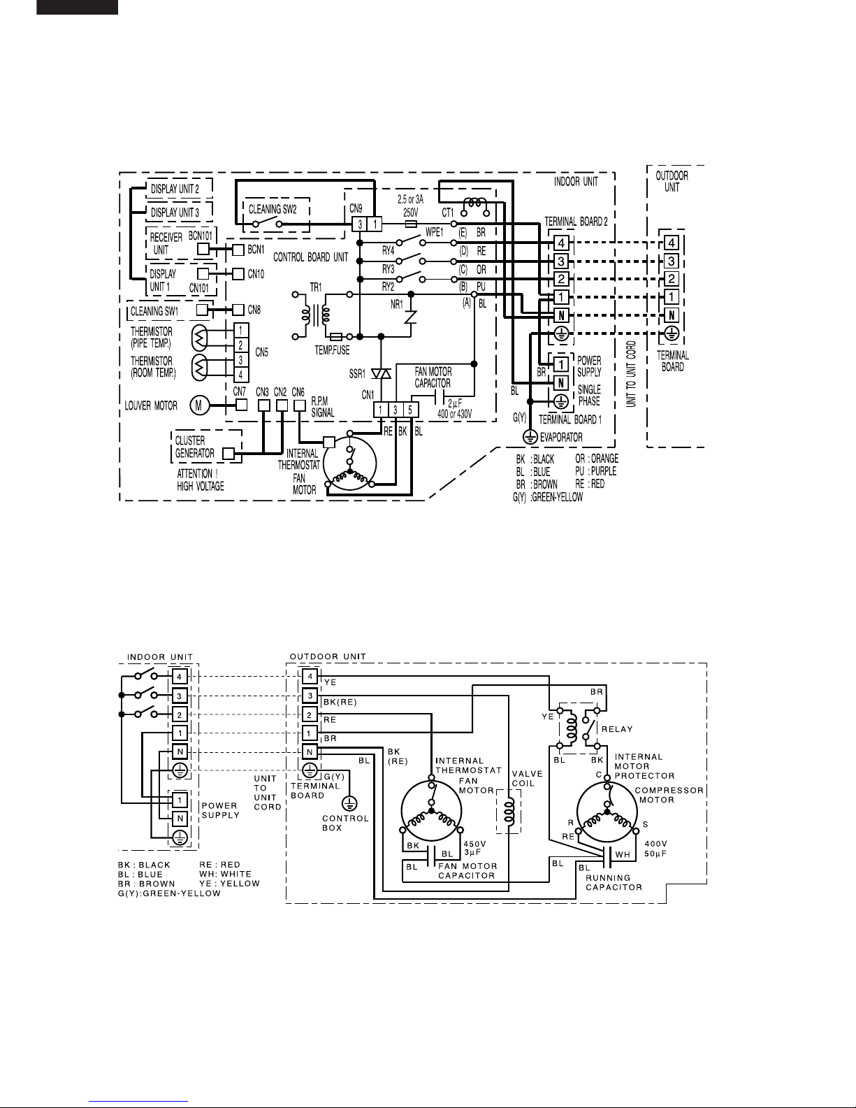
Figure W-3. Wiring Diagram for AY-AP24CE
Figure W-4. Wiring Diagram for AE-A24CE
Page 7
AY-AP18CE AY-AP24CE
AH-AP18CE AH-AP24CE
AE-A18CE AE-A24CE
AU-A18CE AU-A24CE
7
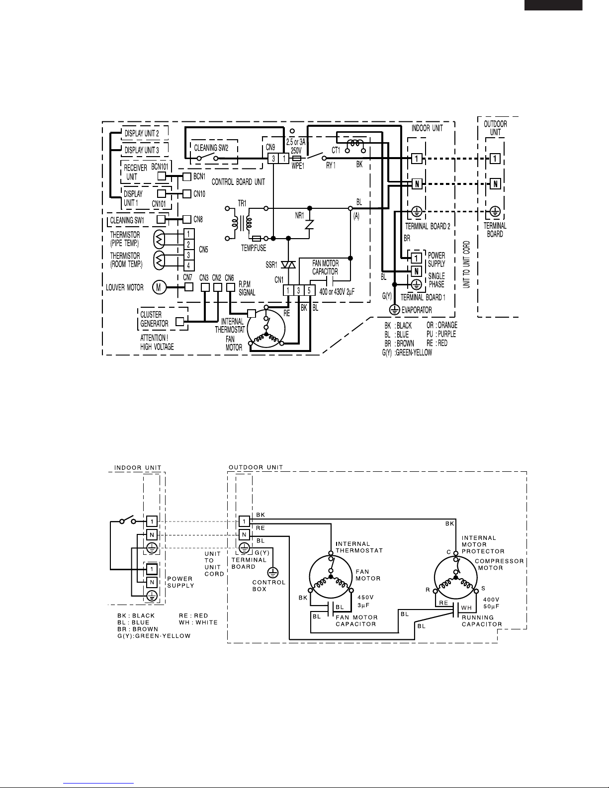
Figure W-5. Wiring Diagram for AH-AP18CE
Figure W-6. Wiring Diagram for AU-A18CE
Page 8
AY-AP18CEAY-AP24CE
AH-AP18CEAH-AP24CE
AE-A18CE AE-A24CE
AU-A18CE AU-A24CE
8
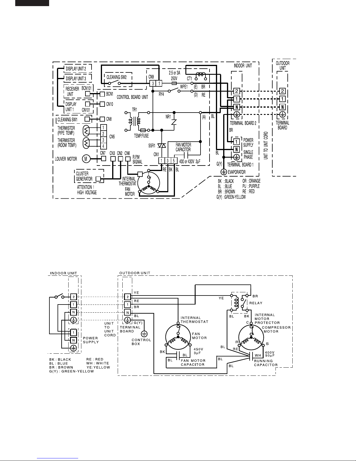
Figure W-7. Wiring Diagram for AH-A24CE
Figure W-8. Wiring Diagram for AU-A24CE
Page 9
AY-AP18CE AY-AP24CE
AH-AP18CE AH-AP24CE
AE-A18CE AE-A24CE
AU-A18CE AU-A24CE
9
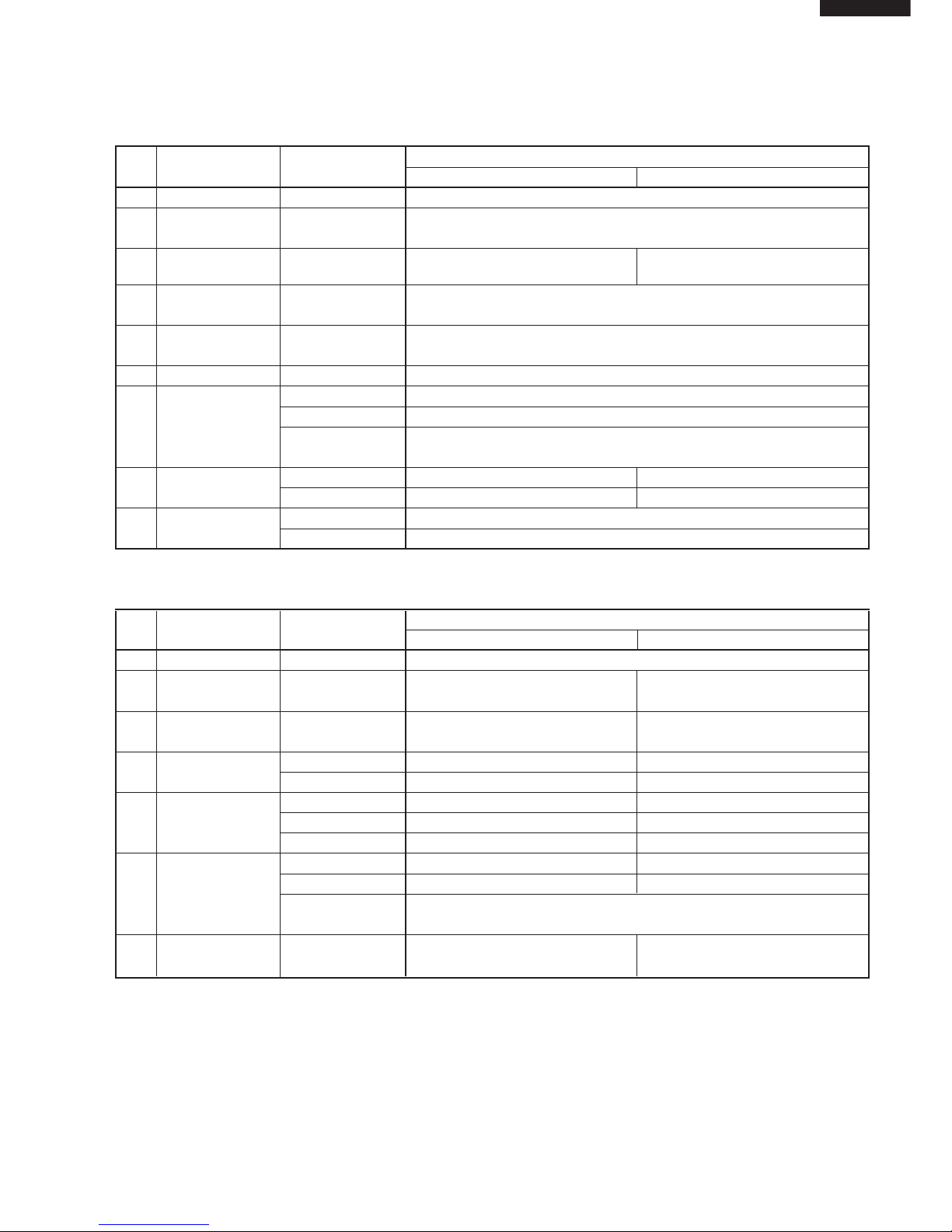
Part Part Name Items Specifications
No. AY-AP18CE AY-AP24CE
1 Terminal Board Rating 300V 25A
2 Fan motor Rating 400V 2µF
Capacitor
3 Relay-1 Rating AC250V 20A –
(RY1) Coil Volt.; 12V
4 Relay-2 Rating AC250V 3A
(RY2, RY3, RY4) Coil Volt.; 12V
5 Printed Wiring Material Paper Base Phenolic Resin (UL 94V-0)
Board
6 Transformer Rating Pri 220 - 240VAC Sec. 19.0VDC
7 Fan motor Rating 220 - 240VAC 50Hz 41W 4-Pole
Type MLA999
Thermal
Protector
Cut off 135±10˚C
(Internal)
8 Power Supply Rating 3G 1.5mm
2
–
Cord H05VV-F –
9 Louver Motor Rating DC12V
Type MP24GA
Part Part Name Items Specifications
No. AE-A18CE AE-A24CE
1 Terminal Board Rating 300V 25A
2 Fan motor Rating 450V 3µF 450V 3µF
Capacitor
3 Running Rating 400V 50µF 400V 50µF
Capacitor
4 Compessor Rating AC220 - 240V 50Hz 1500W AC220 - 240V 50Hz 2200W
Type PH33VPET 2JS464D3AA02
5 Protector Manufacturer Ubukata Industries Co., Ltd. TEXAS INSTRUMENTS
Type UP3QF0302-T09 (INTERNAL) 3HM529-36V
Cutt off 130˚C 120˚C
6 Fan motor Rating
220 - 240VAC 50Hz 71W 6-Pole 220 - 240VAC 50Hz 75W 6-Pole
Type MLB002 MLB015
Thermal protector Cut off 135˚C±5˚C
(Internal)
7 Relay 5 Rating – AC250V 30A
for Compressor Coil volt: 200 -240VAC
ELECTRICAL PARTS
Page 10
AY-AP18CEAY-AP24CE
AH-AP18CEAH-AP24CE
AE-A18CE AE-A24CE
AU-A18CE AU-A24CE
10
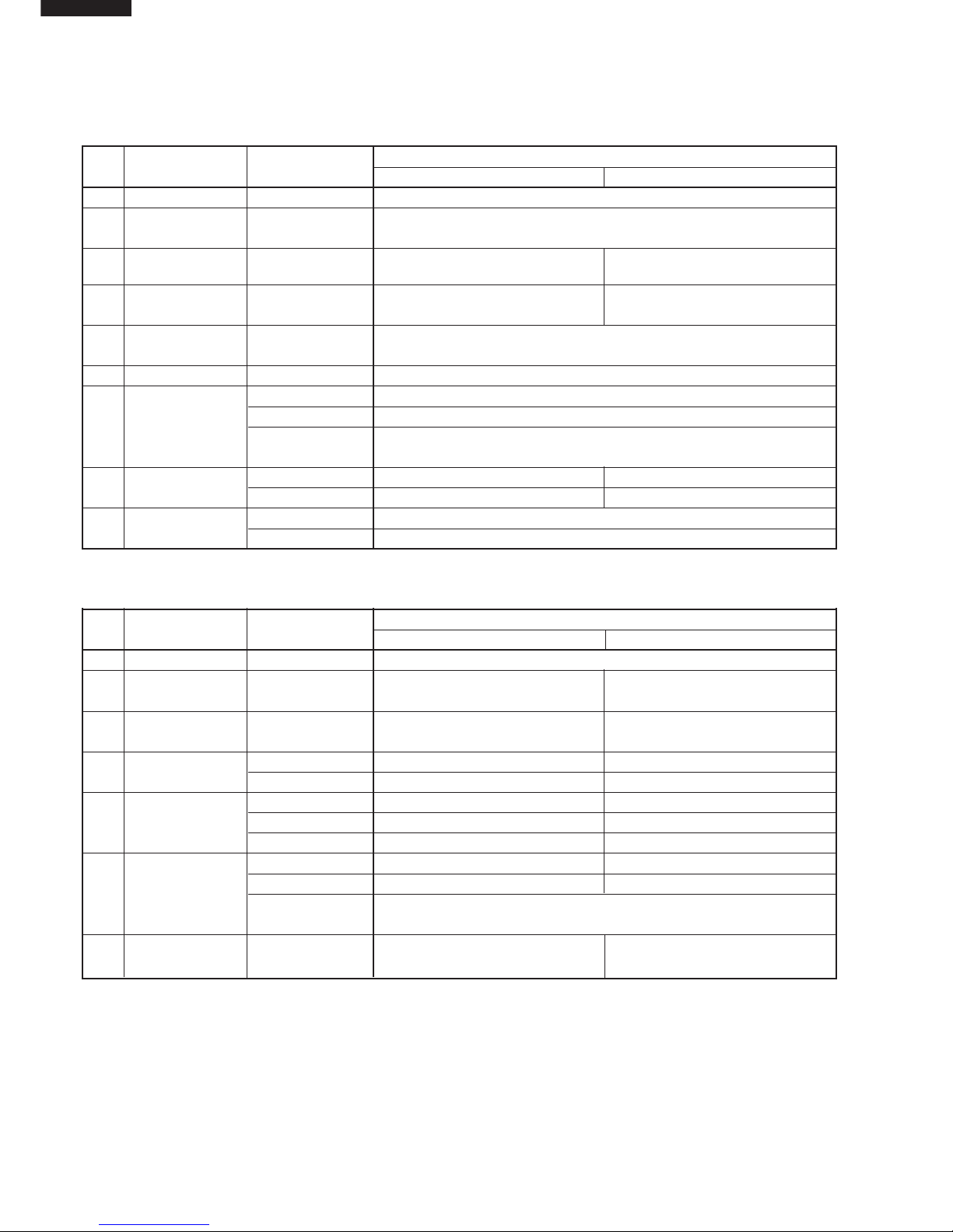
Part Part Name Items Specifications
No. AH-AP18CE AH-AP24CE
1 Terminal Board Rating 300V 25A
2 Fan motor Rating 400V 2µF
Capacitor
3 Relay-1 Rating AC250V 20A –
(RY1) Coil Volt.; 12V
4 Relay-2 Rating – AC250V 5A
(RY4) Coil Volt.; 12V
5 Printed Wiring Material Paper Base Phenolic Resin (UL 94V-0)
Board
6 Transformer Rating Pri 220 - 240VAC Sec. 16.8V DC 0.29A
7 Fan motor Rating 220 - 240VAC 50Hz 41W 4-Pole
Type MLA999
Thermal
Protector
Cut off 135±10˚C
(Internal)
8 Power Supply Rating 3G 1.5mm
2
–
Cord Type H05VV-F –
9 Louver Motor Rating DC12V 250
Type MP35EA
Part Part Name Items Specifications
No. AU-A18CE AU-A24CE
1 Terminal Board Rating 300V 25A
2 Fan motor Rating 450V 3µF 450V 3µF
Capacitor
3 Running Rating 400V 50µF 400V 50µF
Capacitor
4 Compessor Rating AC220 - 240V 50Hz 1500W AC220 - 240V 50Hz 2200W
Type PH33VPET 2JS464D3AA02
5 Protector Manufacturer Ubukata Industries Co., Ltd. TEXAS INSTRUMENTS
Type UP3QF0302-T09 (INTERNAL) 3HM529-36V
Cutt off 130˚C 120˚C
6 Fan motor Rating
220 - 240VAC 50Hz 71W 6-Pole 220 - 240VAC 50Hz 75W 6-Pole
Type MLB002 MLB015
Thermal protector Cut off 135˚C±5˚C
(Internal)
7 Relay 4 Rating – AC250V 30A
Coil volt: 200 -240V
Page 11
AY-AP18CE AY-AP24CE
AH-AP18CE AH-AP24CE
AE-A18CE AE-A24CE
AU-A18CE AU-A24CE
11
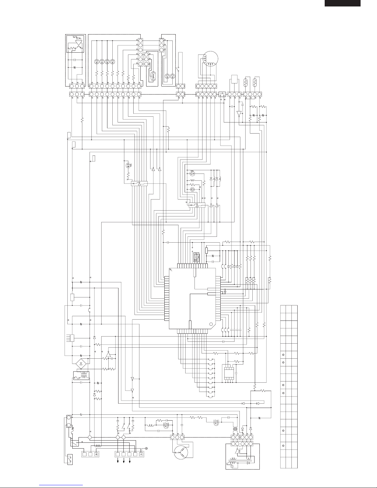
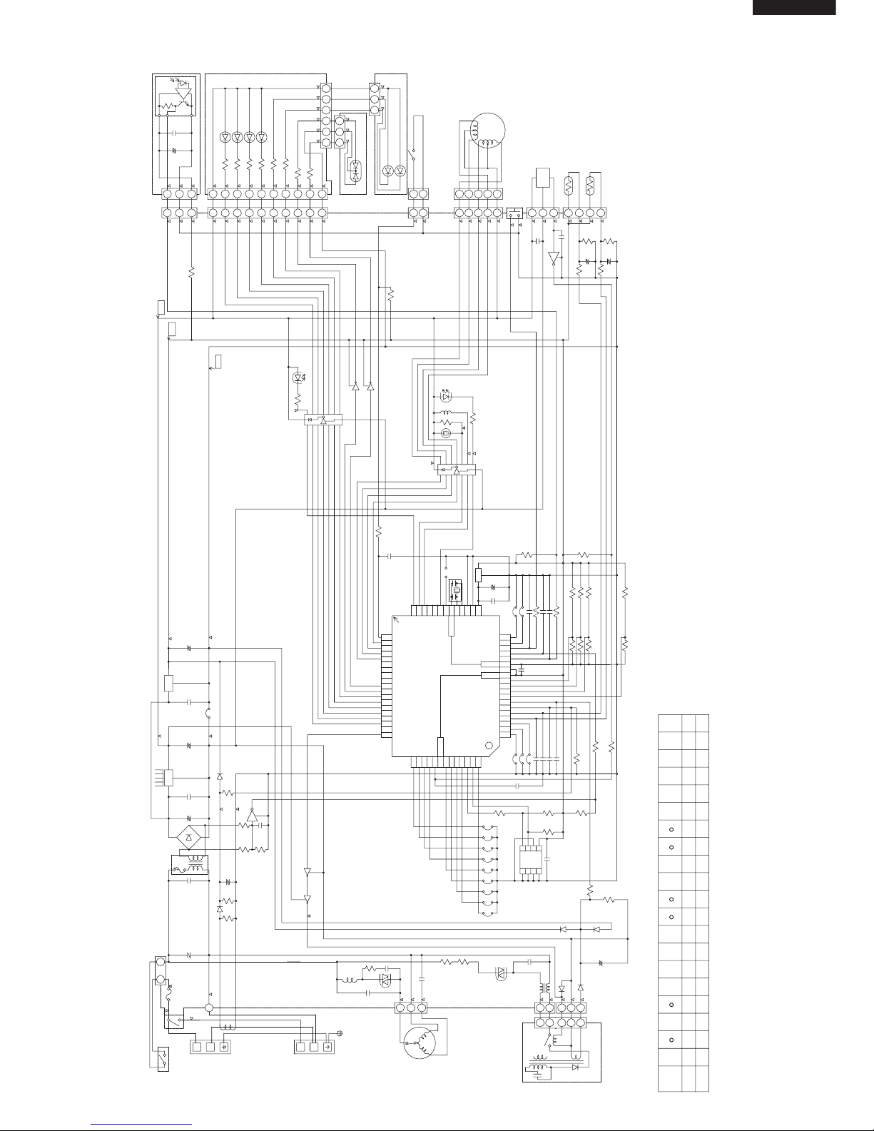
MICROCOMPUTER CONTROL SYSTEM
Figure L-1. Electronic Control Circuit Diagram for AY-AP18CE
15K
L2
R37
MODE
OUTDOOR
UNIT
BR
BK
BL
C
B
A
VALVE
BOARD
TERMINAL
3
2
POWER
SUPPLY
SINGLE
PHASE
N
1
TERMINAL
BOARD
N
1
RY2
3A
250VTWPE1
RY1
OUT
IN
R38
JP19
JP7
JP8
JP9
NC
NC
NC
NC
R2
R1
2W
2W
SSR2
6
8
C28
275V
0.1µ
0.1µ
275V
275V
CN101
CN102
BCN102
CN103
CN10
270
56
1/2W
1/2W
620
620
2345678
1
321
620
620
R106
R105
R104
R103
BCN101
IC101
+
10V
33µ
25V
0.1µ
C101
C102
1/2W
1/2W
R101
R102
2.7K
3K
LED103
LED104
LED105
LED106
(FAN AUTO)
(FAN H)
(FAN M)
(FAN L)
R107
9
65 243 1
(CLUSTER)
LED107
GR
BL
21
1
(OPERATION)
LED101
LED102
(TIMER)
23
10
R108
3
D12
0.1µ
1
1K(F)
53176
R37
8765432
BCN1
1
123
C26
+
+
R33 R31
1
0.1µ
25V
C16
SW1 : AUX.(TEST RUN)
C12
C27
13K
3.3K
R17
16V
0.01µ
16V
0.01µ
10K
10K
JP18
JP13
JP12
JP11
JP10
10MHz
R11
47K
R12
6.8K
0.01µ
0.01µ
0.01µ
16V
16V
16V
10K
R34
R32
R26
R25
R24
R23
R22
R21
R20
R19
R18
R16
R15
R14
R13
R10
R9
R8
R7
C25
C23
C21
C20
C19
C18
C17C15
C14
C13
C11
C9
C8C6
C5
C4
C3
C2
C1
TR1
0.01µ
16V
25V
0.1µ
678
321
IC8
5
4
3.3K
22.6K(F)
GND
D1?4
C7
+
100µ
10V
25V
IC3
0.1µ
7805
47µ
25V
+
IC2
7812
0.1µ
50V
1000µ
35V
+
D7
2.7K(F)
531
2µ
MOTOR
FAN
TH1 PIPE
TEMP.
10kΩ(25˚C)
TH2 PIPE
TEMP.
15kΩ(25˚C)
123
4
(F)
10K
(F)
10k
10µ
16V 16V
10µ
10K10K
680
+
1000p
50V
Vss
AVss
AVcc
48
47
46
45
44
43
42
41
40
39
38
37
36
35
34
33
51
50
49
P20
P17
P16
P15
P14
P13
P12
P11
P10
P07
P06
P05
P04
P03
P02
P01
P00
NC
P30
64636261605958575655545352
P44
P43
P42
P41
P40
P37
P36
P35
P34
P33
P32
P31
P64
P63
P62
P61
P60
AVR
AN7
AN6
AN5
AN4
AN3
AN2
AN1
AN0
P47
P46
P45
19
18
17
16
15
14
13
12
11
10
9
8
7
6
5
4
3
2
1
Vcc
20212223242526272829303132
RST
MOD0
MOD1
X0X1P27
P26
P25
P24
P23
P22
P21
FRONT
OSC1
0.01µ
1K
JP4
JP5
16V
0.01µ
400V
(PATTERN SIDE)
IC1
50V
1µ
0.1µ
25V
13K
13K
10K
3
IC6
1
MB89537A
NC
JP1
JP2
JP3
3
2
FAN
MOTOR
IC
HOLE
321
4
5
123
LOUVER
MOTOR
35421
0.1µ
25V
D6
+
10K(F)
220µ
16V
Q1
2
3
1
1
2
3
9
8
IC5
Q3
Q4
470
1/2W
SSR1
RY1
BZ1
1.8K
R28
R29
RY2
RY3
D10
D11
10K
IC4
8
2
11
2
SW101
C24
25V
9
10
5V
12V
3
SSR2
R30
470
9
1/2W
2
R27
R4
22K
R5
1
Q2
20K
R6
22K
16V
C10
0.01µ
2
16V
C22
0.01µ
2
2
3
3
2
1
2
3
D9 D8
13
CLEANING
SWITCH 2
SWITCH 1
CLEANING
10K
R39
R40
3.3K
R35
CLUSTER
1
3
2
1
CN1
CN2
CN3
CN5
CN6
CN7
CN8
INTERNAL
THERMOSTAT
CN9
NR1
131
3
JP21
Q5
Q6
Q7Q8
1W
R43
C33
0.033µ
100
275V
RY3
0.033µ
275V
R42
C32
100
1W
0.033µ
275V
1W
C31
SSR1
L1
100
R41
6.8K
6.8K
NF1
+
C29
47µ
25V
D14
10K
1/2W
R4547
R38
L
MODE
COOLHEAT
FAN1 FAN2
R23R21R19
ERTER
CLUS
FAN
OUT LOUV
JP19JP18
15K15K15KNONE
JP6
NONE
TEST
JP13JP12JP11JP10
JP9JP8JP7
NONE NONE NONE NONE
2
PIPE
1
PIPE
FAN
DRY
E 2
DEIC
E 1
DEIC
13KNONE NONE NONE
JP1 JP5JP4JP3JP2
I
SYMBOL
DEF.
HOT
KEEP
SWE-
AT
WIRE
LESS
PWR
ON
BL
ORPU
CT1
BL
COMP
FAN
TO
Page 12
AY-AP18CEAY-AP24CE
AH-AP18CEAH-AP24CE
AE-A18CE AE-A24CE
AU-A18CE AU-A24CE
12
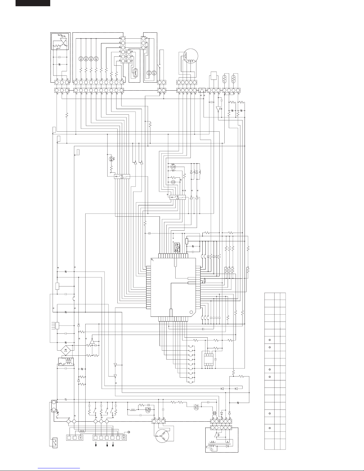
Figure L-2. Electronic Control Circuit Diagram for AY-AP24CE
13K
R37
L2L1
MODE
6.8K47K
10K
25V
47µ
C29
+
D14
NF1
6.8K
6.8K
275V
0.033µ
C31
1W
R41
100
L1
RY3
0.033µ
275V
1W
100
RY2
C32
R42
275V
100
0.033µ
275V
1W
C33
R43
RY4
R44
0.01µ
C34
1W
NC
NC
NC
NC
R38
JP19
JP7
JP8
JP9
0.1µ
275V
C28
8
6
SSR2
2W
2W
R1
R2
0.1µ
275V
275V
CN101
CN10
CN102
BCN102
CN103
3
R108
10
32
(TIMER)
LED102
LED101
(OPERATION)
1
12
BL
GR
LED107
(CLUSTER)
134256
9
R107
(FAN L)
(FAN M)
(FAN H)
(FAN AUTO)
LED106
LED105
LED104
LED103
3K
2.7K
R102
R101
1/2W
1/2W
C102
C101
0.1µ
25V
33µ
10V
+
IC101
BCN101
R103
R104
R105
R106
620
620
123
1
8765432
620
620
1/2W
1/2W
56
270
D12
0.1µ
820(F)
53176
Q8 Q7
Q6
Q5
JP21
3
131
NR1
CN9
THERMOSTAT
INTERNAL
CN8
CN7
CN6
CN5
CN3
CN2
CN1
1
2
3
1
CLUSTER
R35
3.3K
R40
R39
10K
CLEANING
SWITCH 1
SWITCH 2
CLEANING
31
D8D9
3
2
1
2
3
3
2
1
2
0.01µ
C22
16V
2
0.01µ
C10
16V
22K
R6
20K
Q2
1
R5
22K
R4
R27
2
1/2W
9
470
R30
SSR2
3
12V
5V
10
9
25V
C24
SW101
2
11
2
8
IC4
10K
D11
D10
RY3
RY2
R29
R28
1.8K
BZ1
RY4
SSR1
1/2W
470
Q4
Q3
IC5
8
9
3
2
1
1
3
2
Q1
16V
220µ
10K(F)
+
D6
25V
0.1µ
1
2
453
MOTOR
LOUVER
32154
123
HOLE
IC
FAN
MOTOR
2
3
JP3
JP2
JP1
NC
MB89537A
1
IC6
3
10K
13K
13K
25V
0.1µ
1µ
50V
IC1
(PATTERN SIDE)
400V
0.01µ
16V
JP5
JP4
1K
0.01µ
SSR1
OSC1
FRONT
P21
P22
P23
P24
P25
P26
P27X1X0
MOD1
MOD0
RST
32313029282726252423222120
Vcc
1
2
3
4
5
6
7
8
9
10
11
12
13
14
15
16
17
18
19
P45
P46
P47
AN0
AN1
AN2
AN3
AN4
AN5
AN6
AN7
AVR
P60
P61
P62
P63
P64
P31
P32
P33
P34
P35
P36
P37
P40
P41
P42
P43
P44
52535455565758596061626364
P30
NC
P00
P01
P02
P03
P04
P05
P06
P07
P10
P11
P12
P13
P14
P15
P16
P17
P20
49
50
51
33
34
35
36
37
38
39
40
41
42
43
44
45
46
47
48
AVcc
AVss
Vss
50V
1000p
+
680
10K 10K
10µ
16V16V
10µ
10k
(F)
10K
(F)
432
1
TH2
PIPE TEMP.
15kΩ(25˚C)
TH1
PIPE TEMP.
10kΩ(25˚C)
FAN
MOTOR
2µ
135
2.7K(F)
D7
+
35V
1000µ
50V
0.1µ
7812
IC2
+
25V
47µ
7805
0.1µ
IC3
25V
10V
100µ
+
C7
D1?4
GND
22.6K(F)
3.3K
4
5
IC8
123
876
0.1µ
25V
16V
0.01µ
TR1
C1
C2
C3
C4
C5
C6 C8
C9
C11
C13
C14
C15 C17
C18
C19
C20
C21
C23
C25
R7
R8
R9
R10
R13
R14
R15
R16
R18
R19
R20
R21
R22
R23
R24
R25
R26
R32
R34
10K
16V
16V
16V
0.01µ
0.01µ
0.01µ
6.8K
R12
47K
R11
10MHz
JP10
JP11
JP12
JP13
JP18
10K
10K
0.01µ
16V
0.01µ
16V
R17
3.3K
13K
C27
R37
C12
SW1 : AUX.(TEST RUN)
C16
25V
0.1µ
1
R31R33
+
+
C26
321
1
BCN1
2345678
L
FAN
WPE1T250V
3A
1
N
BOARD
TERMINAL
1
N
PHASE
SINGLE
SUPPLY
POWER
2
3
4
TERMINAL
BOARD
VALVE
COMP
A
B
C
D
E
BR
UNIT
OUTDOOR
TO
47 R45
1/2W
DEF.
SYMBOL
I
JP2 JP3 JP4 JP5JP1
NONENONENONE
R38
MODE
JP18
15K 15KNONE
JP19
LOUVOUT
FAN
CLUS
TER ER
R19 R21 R23
FAN2FAN1
HEAT COOL
JP6
NONE
E 1
DEIC
E 2
DRY
FAN
PIPE
1
PIPE
2
JP7 JP8 JP9
JP10 JP11 JP12 JP13
NONENONENONENONE
TEST
DEIC
ON
PWR
LESS
WIRE
AT
SWE-
KEEP
HOT
CT1
BL
BL
PU
OR
RE
BR
Page 13
AY-AP18CE AY-AP24CE
AH-AP18CE AH-AP24CE
AE-A18CE AE-A24CE
AU-A18CE AU-A24CE
13
Figure L-3. Electronic Control Circuit Diagram for AH-AP18CE
MODE
13K
R37
L2
NC
NC
56
L 1
9.1K
R45
1/2W
10K
D14
25V
47
µ
C29
+
NF1
6.8K
6.8K
R41
100
L1
SSR1
C31
1W
275V
0.033
µ
Q8 Q7
Q6
Q5
JP21
3
131
NR1
CN9
THERMOSTAT
INTERNAL
CN8
CN7
CN6
CN5
CN3
CN2
CN1
1
2
3
1
CLUSTER
R35
3.3K
R40
R39
10K
CLEANING
SWITCH 1
SWITCH 2
CLEANING
31
D8D9
3
2
1
2
3
3
2
2
0.01
µ
C22
16V
2
0.01µ
C10
16V
22K
R6
20K
Q2
1
R5
22K
R4
R27
2
1/2W
9
470
R30
SSR2
3
12V
5V
10
9
25V
C24
SW101
2
11
2
8
IC4
10K
R29
R28
1.8K
BZ1
RY1
SSR1
1/2W
470
IC5
8
9
Q1
16V
220µ
10K(F)
+
D6
25V
0.1µ
1
2
453
MOTOR
LOUVER
32154
123
HOLE
IC
FAN
MOTOR
2
3
JP3
JP2
JP1
NC
MB89537A
1
IC6
3
10K
13K
13K
25V
0.1
µ
1
µ
50V
IC1
(PATTERN SIDE)
400V
0.01µ
16V
JP5
JP4
1K
0.01
µ
OSC1
FRONT
P21
P22
P23
P24
P25
P26
P27X1X0
MOD1
MOD0
RST
32313029282726252423222120
Vcc
1
2
3
4
5
6
7
8
9
10
11
12
13
14
15
16
17
18
19
P45
P46
P47
AN0
AN1
AN2
AN3
AN4
AN5
AN6
AN7
AVR
P60
P61
P62
P63
P64
P31
P32
P33
P34
P35
P36
P37
P40
P41
P42
P43
P44
52535455565758596061626364
P30
NC
P00
P01
P02
P03
P04
P05
P06
P07
P10
P11
P12
P13
P14
P15
P16
P17
P20
49
50
51
33
34
35
36
37
38
39
40
41
42
43
44
45
46
47
48
AVcc
AVss
Vss
50V
1000p
+
680
10K 10K
10
µ
16V16V
10
µ
10k
(F)
10K
(F)
432
1
TH2
PIPE TEMP
15kΩ(25˚C).
TH1
PIPE TEMP
10kΩ(25˚C).
FAN
MOTOR
2µ
135
2.7K(F)
D7
+
35V
1000µ
50V
0.1µ
7812
IC2
+
25V
47µ
7805
0.1µ
IC3
25V
10V
100µ
+
C7
D1?4
GND
22.6K(F)
3.3K
4
5
IC8
123
876
0.1µ
25V
16V
0.01µ
TR1
C1
C2
C3
C4
C5
C6 C8
C9
C11
C13
C14
C15 C17
C18
C19
C20
C21
C23
C25
R7
R8
R9
R10
R13
R14
R15
R16
R18
R19
R20
R21
R22
R23
R24
R25
R26
R32
R34
10K
16V
16V
16V
0.01µ
0.01µ
0.01µ
6.8K
R12
47K
R11
10MHz
JP10
JP11
JP12
JP13
JP18
10K
10K
0.01µ
16V
0.01
µ
16V
R17
3.3K
13K
C27
C12
SW1 : AUX.(TEST RUN)
C16
25V
0.1
µ
1
R31R33
+
+
C26
321
1
BCN1
2345678
R37
6
7
135
1K(F)
1
0.1µ
D12
3
R108
10
32
(TIMER)
LED102
LED101
(OPERATION)
1
12
BL
GR
LED107
(CLUSTER)
134256
9
R107
(FAN L)
(FAN M)
(FAN H)
(FAN AUTO)
LED106
LED105
LED104
LED103
3K
2.7K
R102
R101
1/2W
1/2W
C102
C101
0.1µ
25V
33µ
10V
+
IC101
BCN101
R103
R104
R105
R106
620
620
123
1
8
76543
2
620
620
1/2W
1/2W
56
CN10
CN103
BCN102
CN102
CN101
275V
275V
0.1
µ
0.1
µ
275V
C28
8
6
SSR2
2W
2W
R1
R2
NC
NC
NC
NC
JP9
JP8
JP7
JP19
DEIC
E 1
DEIC
E 2
DRY
FAN
PIPE
1
PIPE
2
NONENONENONENONE
JP7 JP8 JP9
JP10 JP11 JP12 JP13
TEST
NONE
JP6
NONE 15K 15K 15K
JP18 JP19
LOUVOUT
FAN
CLUS
TER ER
R19 R21 R23
FAN2FAN1
HEAT COOL
MODE
R38
R38
ON
PWR
LESS
WIRE
AT
SWE-
KEEP
HOT
DEF.
SYMBOL
I
JP2 JP3 JP4 JP5JP1
IN
OUT
RY1
WPE1T250V
3A
1
N
BOARD
TERMINAL
1
N
PHASE
SINGLE
SUPPLY
POWER
TERMINAL
BOARD
A
BL
BK
BR
UNIT
OUTDOOR
TO
NONENONENONE
47
CT1
BL
BL
Page 14

AY-AP18CEAY-AP24CE
AH-AP18CEAH-AP24CE
AE-A18CE AE-A24CE
AU-A18CE AU-A24CE
14
Figure L-4. Electronic Control Circuit Diagram for AH-AP24CE
L2
R37
13K
MODEHOT
KEEP
SWE-
AT
WIRE
LESS
PWR
ON
DEIC
TEST
NONE NONE NONE NONE
JP13JP12JP11JP10
JP9JP8JP7
2
PIPE
1
PIPE
FAN
DRY
E 2
DEIC
E 1
NONE
JP6
COOLHEAT
FAN1 FAN2
R23R21R19
ERTER
CLUS
FAN
OUT LOUV
JP19
NONE 15K15K
JP18
MODE
L
R38
NONE NONE NONE
JP1 JP5JP4JP3JP2
I
SYMBOL
DEF.
1/2W
R4547
TO
OUTDOOR
UNIT
BR
E
A
BOARD
TERMINAL
2
POWER
SUPPLY
SINGLE
PHASE
N
1
TERMINAL
BOARD
N
1
3A
250VTWPE1
8765432
BCN1
1
123
C26
+
+
R33 R31
1
0.1µ
25V
C16
SW1 : AUX.(TEST RUN)
C12
R37
C27
13K
3.3K
R17
16V
0.01µ
16V
0.01µ
10K
10K
JP18
JP13
JP12
JP11
JP10
10MHz
R11
47K
R12
6.8K
0.01µ
0.01µ
0.01µ
16V
16V
16V
10K
R34
R32
R26
R25
R24
R23
R22
R21
R20
R19
R18
R16
R15
R14
R13
R10
R9
R8
R7
C25
C23
C21
C20
C19
C18
C17C15
C14
C13
C11
C9
C8C6
C5
C4
C3
C2
C1
TR1
0.01µ
16V
25V
0.1µ
678
321
IC8
5
4
3.3K
22.6K(F)
GND
D1?4
C7
+
100µ
10V
25V
IC3
0.1µ
7805
47µ
25V
+
IC2
7812
0.1µ
50V
1000µ
35V
+
D7
2.7K(F)
531
2µ
MOTOR
FAN
123
4
(F)
10K
(F)
10k
10µ
16V 16V
10µ
10K10K
680
+
1000p
50V
Vss
AVss
AVcc
48
47
46
45
44
43
42
41
40
39
38
37
36
35
34
33
51
50
49
P20
P17
P16
P15
P14
P13
P12
P11
P10
P07
P06
P05
P04
P03
P02
P01
P00
NC
P30
64636261605958575655545352
P44
P43
P42
P41
P40
P37
P36
P35
P34
P33
P32
P31
P64
P63
P62
P61
P60
AVR
AN7
AN6
AN5
AN4
AN3
AN2
AN1
AN0
P47
P46
P45
19
18
17
16
15
14
13
12
11
10
9
8
7
6
5
4
3
2
1
Vcc
20212223242526272829303132
RST
MOD0
MOD1
X0X1P27
P26
P25
P24
P23
P22
P21
FRONT
OSC1
SSR1
0.01µ
1K
JP4
JP5
16V
0.01µ
400V
(PATTERN SIDE)
IC1
50V
1µ
0.1µ
25V
13K
13K
10K
3
IC6
1
MB89537A
NC
JP1
JP2
JP3
3
2
MOTOR
FAN
IC
HOLE
321
4
5
123
LOUVER
MOTOR
35421
0.1µ
25V
D6
+
10K(F)
220µ
16V
Q1
9
8
IC5
470
1/2W
SSR1
RY4
BZ1
1.8K
R28
R29
10K
IC4
8
2
11
2
SW101
C24
25V
9
10
5V
12V
3
SSR2
R30
470
9
1/2W
2
R27
R4
22K
R5
1
Q2
20K
R6
22K
16V
C10
0.01µ
2
16V
C22
0.01µ
2
1
2
3
3
2
1
2
3
D9 D8
13
CLEANING
SWITCH 2
SWITCH 1
CLEANING
10K
R39
R40
3.3K
R35
CLUSTER
1
3
2
1
CN1
CN2
CN3
CN5
CN6
CN7
CN8
INTERNAL
THERMOSTAT
CN9
NR1
131
3
JP21
Q5
Q6
Q7Q8
6
7
135
820(F)
0.1µ
D12
270
56
1/2W
1/2W
620
620
2345678
1
321
620
620
R106
R105
R104
R103
BCN101
IC101
+
10V
33µ
25V
0.1µ
C101
C102
1/2W
1/2W
R101
R102
2.7K
3K
LED103
LED104
LED105
LED106
(FAN AUTO)
(FAN H)
(FAN M)
(FAN L)
R107
9
65 243 1
(CLUSTER)
LED107
GR
BL
21
1
(OPERATION)
LED101
LED102
(TIMER)
23
10
R108
3
CN103
BCN102
CN102
CN10
CN101
275V
275V
0.1µ
R2
R1
2W
2W
SSR2
6
8
C28
275V
0.1µ
JP9
JP8
JP7
JP19
R38
NC
NC
NC
NC
L1
100
R41
1W
C31
0.033µ
275V
6.8K
6.8K
NF1
D14
+
C29
47µ
25V
10K
275V
RY4
R44
0.01µ
C34
1W
D
NC
NC
47K 5.1K
RE
BL
CT1
BL
BL
BR
TH1 PIPE
TEMP.
10kΩ(25˚C)
TH2 PIPE
TEMP.
15kΩ(25˚C)
Page 15
AY-AP18CE AY-AP24CE
AH-AP18CE AH-AP24CE
AE-A18CE AE-A24CE
AU-A18CE AU-A24CE
15
2
FB441
2
FB441
2
2
FB441
2
FB441
2
TO TERMINAL BOARD
TOPN
TO TERMINAL BOARD
TOPN
TO TERMINAL BOARD
BOTTOMN
TO TERMINAL
BOARD TOP
3
TO TERMINAL
BOARD TOP
2
FROM TERMINAL BOARD
TOP1BLACK
FROM
TERMINAL
BOARD BOTTOM
1BROWN
FROM FAN MOTOR
FROM
FAN MOTOR
FROM CLUSTER GENERATOR
FROM
CLUSTER
GENERATOR
FROM CLEANING SWITCH 1
FROM
CLEANING
SWITCH 2
FROM THERMISTOR
FROM LOUVER MOTOR
BCN101(BCN201)
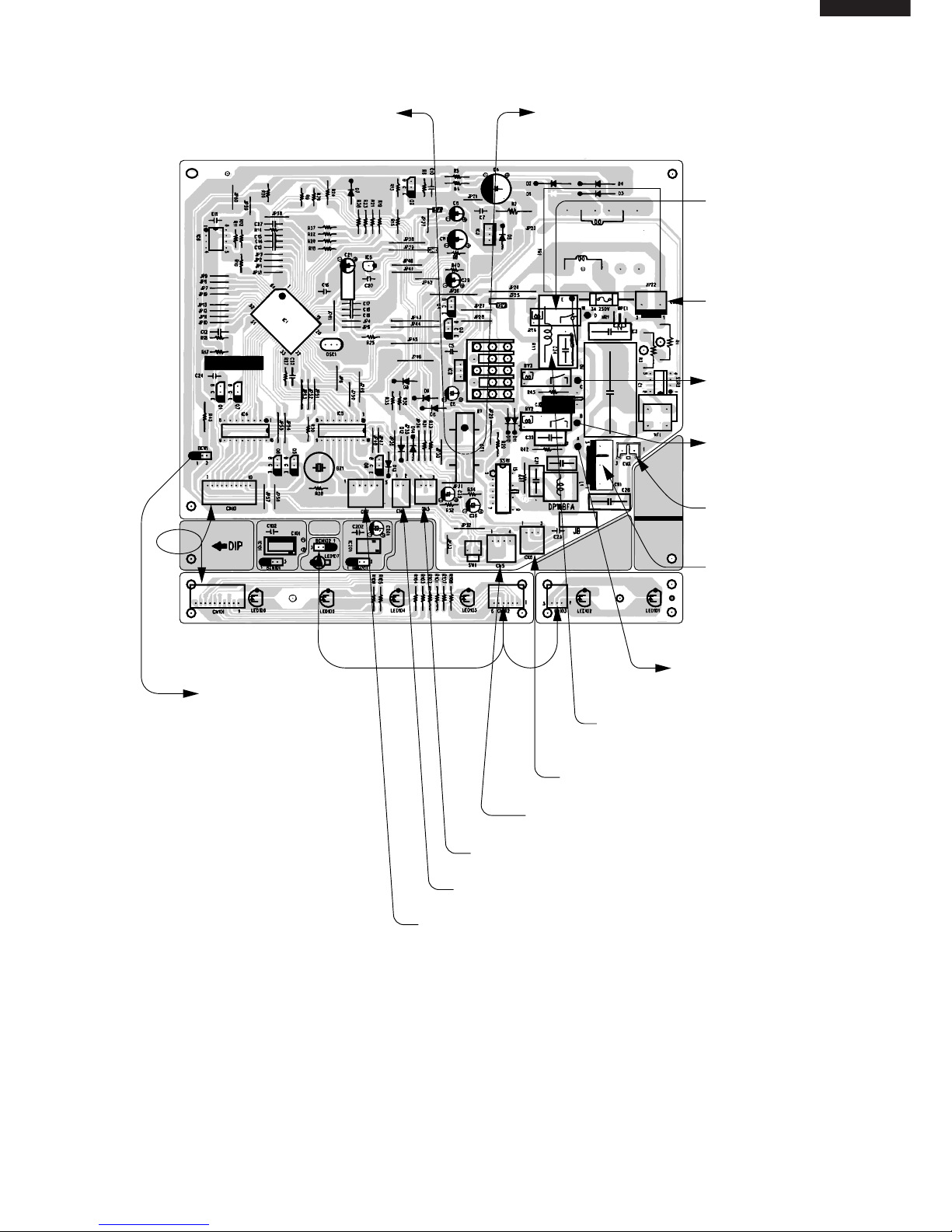
Figure L-5. Printed Wiring Diagram for AY-AP18CE
Page 16
AY-AP18CEAY-AP24CE
AH-AP18CEAH-AP24CE
AE-A18CE AE-A24CE
AU-A18CE AU-A24CE
16
2
FB441
2
FB441
2
2
FB441
2
FB441
2
TO TERMINAL BOARD
TOPN
TO TERMINAL BOARD
TOPN
TO TERMINAL BOARD
BOTTOMN
TO TERMINAL
BOARD TOP
3
TO TERMINAL
BOARD TOP
4
TO TERMINAL
BOARD TOP
2
TO TERMINAL
BOARD BOTTOM
1
FROM FAN MOTOR
FROM
FAN MOTOR
FROM CLUSTER GENERATOR
FROM
CLUSTER
GENERATOR
FROM CLEANING SWITCH 1
FROM
CLEANING
SWITCH 2
FROM THERMISTOR
FROM LOUVER MOTOR
BCN101(BCN201)
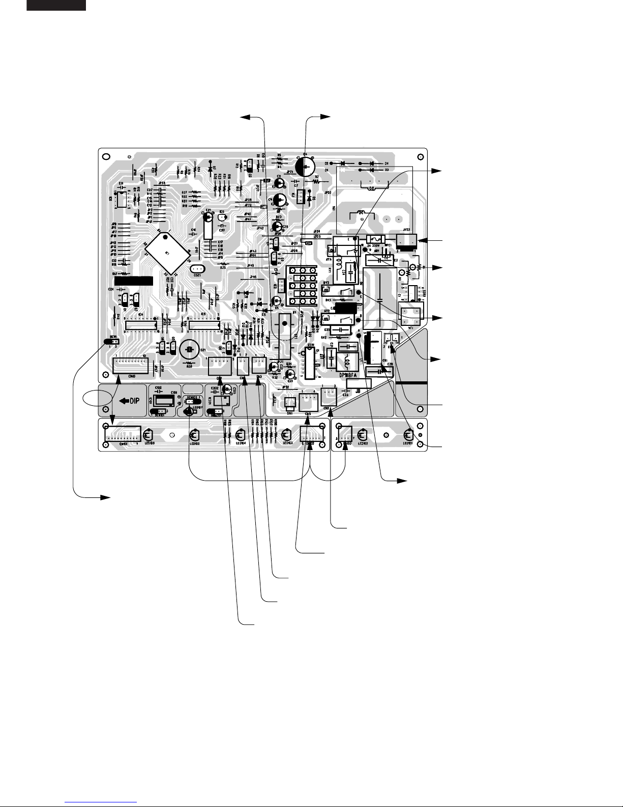
Figure L-6. Printed Wiring Diagram for AY-AP24CE
Page 17
AY-AP18CE AY-AP24CE
AH-AP18CE AH-AP24CE
AE-A18CE AE-A24CE
AU-A18CE AU-A24CE
17
2
FB441
2
FB441
2
2
FB441
2
FB441
2
TO TERMINAL
BOARD TOPN
TO TERMINAL BOARD
TOPN
TO TERMINAL BOARD
BOTTOMN
FROM TERMINAL
BOARD TOP1BLACK
FROM
TERMINAL
BOARD BOTTOM
1BROWN
FROM FAN MOTOR
FROM
FAN MOTOR
FROM CLUSTER GENERATOR
FROM
CLUSTER
GENERATOR
FROM CLEANING SWITCH 1
FROM
CLEANING
SWITCH 2
FROM THERMISTOR
FROM LOUVER MOTOR
BCN101(BCN201)
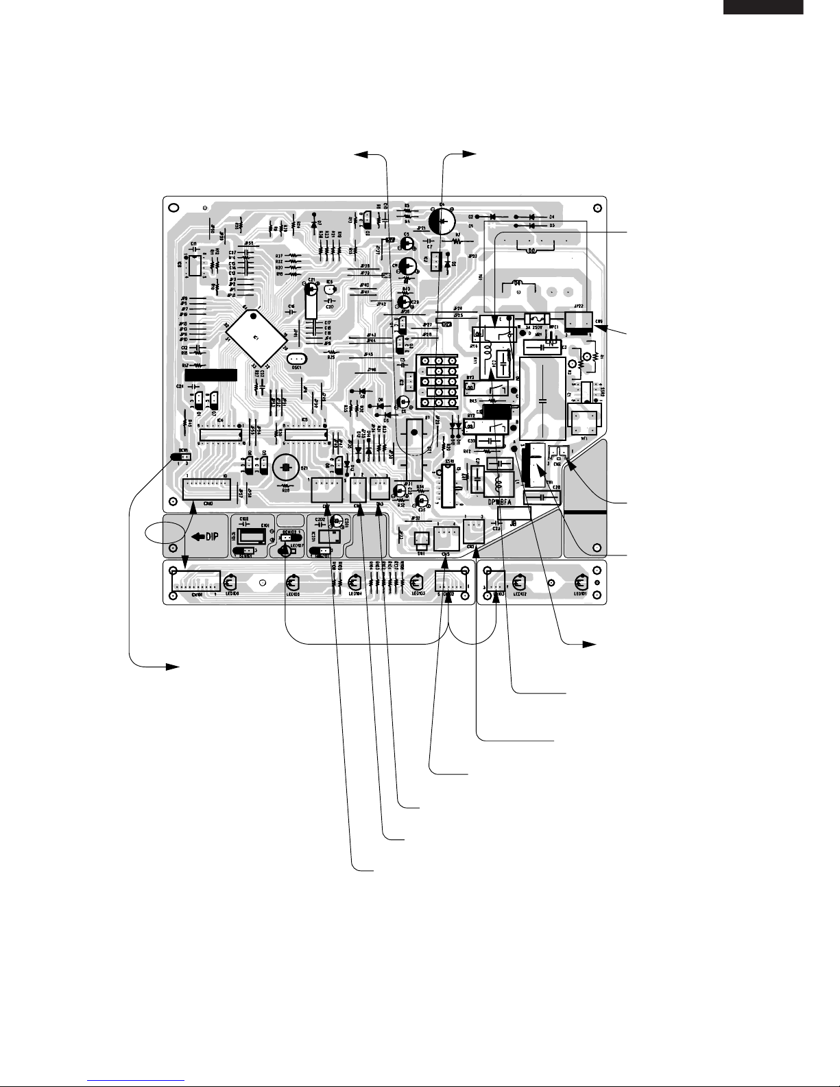
Figure L-7. Printed Wiring Diagram for AH-AP18CE
Page 18

AY-AP18CEAY-AP24CE
AH-AP18CEAH-AP24CE
AE-A18CE AE-A24CE
AU-A18CE AU-A24CE
18
2
FB441
2
FB441
2
2
FB441
2
FB441
2
TO TERMINAL BOARD
TOPN
TO TERMINAL BOARD
TOPN
TO TERMINAL BOARD
BOTTOMN
TO TERMINAL
BOARD TOP
2
TO TERMINAL
BOARD BOTTOM
1
FROM FAN MOTOR
FROM
FAN MOTOR
FROM CLUSTER GENERATOR
FROM
CLUSTER
GENERATOR
FROM CLEANING SWITCH 1
FROM
CLEANING
SWITCH 2
FROM THERMISTOR
FROM LOUVER MOTOR
BCN101(BCN201)
Figure L-8. Printed Wiring Diagram for AH-AP24CE
Page 19

AY-AP18CE AY-AP24CE
AH-AP18CE AH-AP24CE
AE-A18CE AE-A24CE
AU-A18CE AU-A24CE
19
FUNCTIONS
AH-AP18CE/AP24CE are noty provided with the
heating function
1. Temperature control characteristic
1-1 COOL operation
In the “COOL” mode, the thermostat circuit is
controlled by four thermostat lines (C1 thru C5).
Figure Y-1
1-2 DRY operation
In the “DRY” mode, the thermostat circuit is
controlled by three thermostat lines (D1 thru D3).
Figure Y-2
1-3 HEAT operation
In the “HEAT” mode, the thermostat circuit is
controlled by six thermostat lines (H01 thru H4).
Figure Y-3
2. Operation modes
2-1 COOL operation
The compressor turns on or off, at the thermostat
lines C3 and C4. The outdoor fan motor is also
controlled with the compressor.
Figure Y-4
18
32
C1
C2
C3
C4
17.5
18.5
19.5
19.0
20.5
31.5
33.0
32.5
33.5
34.5
Preset temperature (˚C)
Room temperature (˚C)
C5
Room temperature(˚C)
Preset temperature (˚C)
18
32
D1
D2
D3
17.5
18.5
19.5
31.5
32.5
33.5
Preset temperature (˚C)
H4
H3
H2
H1
H02
H01
17.5
18.5
20
21
22
23
31.5
32.5
34.0
35.0
36.0
37.0
18 32
Room temperature(˚C)
Room temperature
Preset temperature
Room
temperature
transition
C4
C5
States 1 & 3 : Compressor ON
State 2 : Compressor OFF
1
2
3
Page 20

AY-AP18CEAY-AP24CE
AH-AP18CEAH-AP24CE
AE-A18CE AE-A24CE
AU-A18CE AU-A24CE
20
Fan switch
DL
Fan speed
Fan switch (AUTO)
18CE TYPE
AY AH AY AH
(r.p.m.)
750 750 830 830
780 780 860 860
820 820 960 960
840 840 980 980
940 940 1030 1030
1000 1000 1120 1120
1050 1050 1210 1210
720 730
840 930
870 960
940 1080
1010 1150
1050 1210
24CE TYPE
DH
DRY
COOL
CL
COOL SOFT
CAL
CM
COOL LOW
CAH
CH
COOL HIGH
HUL
HL
HEAT SOFT
HEAT
HAL
HM
HEAT LOW
HAH
HH
HEAT HIGH
2-2 DRY operation
On the switch on, the compressor always starts to
operate for 2 minutes with fan speed "DL" .
The microcomputer reads the room temperature 2
minutes after this first compressor operation.
This room temperature is set as the preset
temperature automatically.
The preset temperature ranges from 18˚C to
32˚C. When the room temperature is below 18˚C,
the preset temperature is set to 18˚C, and when
the room temperature is over 32˚C, the preset
temperature is set to 32˚C.
Dry operation is divided into three zones (Cooling
zone, Dehumidifying zone and Circulating zone)
by thermostat lines (D1 to D3), and the
compressor and the fan motor are controlled in
each zone as shown in Table Y-1.
Table Y-1
2-3 Heat operation
The compressor turns on or off, at State 2 , turns on
continuously at State 1 & 3 .
Figure Y-5
Room temperature
Preset temperature
Room
temperature
transition
D3
D2
D1
States 1 & 5 : Cooling zone
States 2 & 4 : Dehumidifying zone
States 3 : Circulating zone
3
4
5
1
2
Compressor
Cooling zone
Dehumidifying zone
Circulating zone
Fan speed
ON "DH"
"DL"
"DL" or OFF
ON
OFF
Figure Y-6
Room temperature
Preset temperature
Room
temperature
transition
States 1 & 3 : Compressor ON
States 2 : Compressor OFF/(ON)
(Hot-keep function)
H1
H2
3
1
2
3. Fan speed
Fan speeds are given by the indoor fan motor, "DL"~"HH" which are available in the following operation mode.
Table Y-2
Page 21

AY-AP18CE AY-AP24CE
AH-AP18CE AH-AP24CE
AE-A18CE AE-A24CE
AU-A18CE AU-A24CE
21
MODELS
Fan
LIne
U1
U2
U1
U2
HH HAH HM
12121 2
54˚C 54˚C 54˚C 54˚C 53˚C 53˚C
52˚C 53˚C 52˚C 53˚C 51˚C 52˚C
54˚C 54˚C 54˚C 54˚C 53˚C 53˚C
52˚C 53˚C 52˚C 53˚C 51˚C 52˚C
MODELS
Fan
LIne
U1
U2
U1
U2
HAL HL HUL
12121 2
52˚C 52˚C 52˚C 52˚C 52˚C 52˚C
50˚C 51˚C 50˚C 51˚C 50˚C 51˚C
52˚C 52˚C 52˚C 52˚C 52˚C 52˚C
50˚C 51˚C 50˚C 51˚C 50˚C 51˚C
4. Hot-Keep
This function automatically controls the on-off
operation of the indoor fan motor in accordance
during the heating operation, thereby preventing
the air conditioner from delivering a cold air when
the compressor is off.
When the room temperature exceeds the
thermostat line “H1”, the compressor is turned off,
and the indoor fan motor is turned off after
rotating at “HUL” for 30 seconds. 3 minutes and
10 seconds after turning off the compressor, the
indoor fan motor is turned on for 3 minutes and 20
seconds. At 10 seconds after turning on the
compressor, the indoor fan motor is turned on.
The next compressor OFF time is for 3, 8 or more
than 8 minutes according to the room temperature
(the time increases with a rise of room
temperature) when 3 minutes elapse after turning
on the compessor.
Figure Y-7
5. Preheat air flow
This function is intended to prevent cold air from
being discharged when the heating operation
starts or when defrosting.
When the indoor pipe temperature is below 29˚C
at the begining of the heat operation or after
defrosting, the indoor fan motor stays.
When the indoor pipe temperature gets higher
than 29˚C, the fan motor is turned on at speed
“HUL” after compensation of starting.
When the indoor pipe temperature exceeds 35˚C,
the specified fan speed is restored. When the
indoor pipe temperature falls below 30˚C, the fan
speed shifts down to "HUL". And, when the indoor
pipe temperature falls below 23˚C, the fan motor
turns off. Then, over 29˚C , it turns on again at
speed “HUL”.
Compressor
ON
OFF
Indoor
fan motor
30sec.
time
HUL
ON
OFF
3 min.
3 min.
10sec.
HUL
30sec.
10sec.
Thermo off
Pipe temperature(˚C)
24
29
30
35
OFF
UL UL UL
OFFPreset
Fan speed
OFF
ON
U1
U2
U1 and U2 are defferent by the time.
1 within 3 minutes
3 over 3 minutes
Figure Y-8
6. Overheating protection system
When overloading occurs during the heating operation,
this system controls the outdoor fan motor according to
the indoor pipe temperature to prevent the overloading
of the compressor and restrain the rise in high pressure.
When the indoor pipe temperature exceeds U1˚C, the
outdoor fan motor is turned off, and when the indoor
pipe temperature falls U2˚C, the outdoor fan motor turns
on.
Figure Y-9
Table Y-3
Page 22

AY-AP18CEAY-AP24CE
AH-AP18CEAH-AP24CE
AE-A18CE AE-A24CE
AU-A18CE AU-A24CE
22
Switch ON
Heating
Heating
Heating
Min.
40min.
Max.
12min.
Min.
30min.
Max.
12min.
DefrostDefrost
7. Current control
This system, in order to prevent overcurrent
during heating operation, controls the outdoor fan
motor and changes the indoor fan motor speed by
detecting total current. When the current exceeds
P2, the outdoor fan motor is automatically turned
off, and when the current falls below P4, the
outdoor fan motor is turned on.
When the current exceeds P3 and the indoor fan
speed shifts down because of cold air (5. Preheat
air flow), the changes in the indoor fan speed
shifts up as follows, from "off" to "HUL", or from
"HUL" to "HL". And when the current falls bellow
P5, the indoor fan speed shift up is canceled.
Figure Y-10
8. Freeze preventive
When the indoor pipe temperature falls below 0˚C
during cool operation or dry operation, the
compressor is turned off.
9. Defrost
The defrost timer (integrating the operation time of
compressor) counts time with microcomputer
during heat operation.
Frost of outdoor pipe is estimated by indoor pipe
temperature (TH2), room temperature (TH1),
indoor fan speed and operation state of
compressor.
In the defrost operation, first the compressor is
turned off, the fan speed is set to “HUL” and the
outdoor fan motor is turned off.
30 seconds later the indoor fan motor is turned
off, 60 seconds later the reverse valve is turned
off, and the compressor is turned on. In the end of
defrosting, the compressor is turned off, the
outdoor fan motor is turned on, 60 seconds later
the reverse valve is turned on, and the
compressor is turned on, starting heat operation.
At this time, the indoor fan motor is turned off or
the fan speed is set to “HUL” if preheat air flow
function is effective.
Outdoor
Fan motor
OFF
Indoor
Fan motor
Shift UP
Compressor
OFF
Time
Input current
Current transition
P1 19.0A 22.8A
P2 13.5A 18.1A
P3 12.8A 16.9A
P4 12.4A 16.8A
P5 12.0A 16.0A
AY-AP18CE AY-AP24CE
Figure Y-11
Figure Y-12
10. Delayed operation of the reverse valve
the heat operation is shut down or the operating
mode is switched from heat to cool or dry, or vice
versa, the reverse valve is switched after 3
minutes.
11. Test run
If the "AUX" button on the unit is pressed for 5
seconds or more during operation, cool test
operation starts. The operation LED (red) flickers
during test run.
To put the system in the heating test run mode,
start the cooling operation and select the heating
mode on the remote control. In cool and heat
mode continuous compressor on operation is
performed. In dry mode the operation is in
dehumidifying zone. In fan only mode the indoor
fan motor runs continusly.
12. Timer
12-1 ON/OFF TIMER
When the unit operates during one hour after the
OFF-time is set, thermostat setting is
automatically shifted (+1˚C in cool operation and
dry operation, -3˚C in heat operation, 16˚C 32˚C). When the ON-timer is set in heat operation
and cool operation, operation starts before 0 to 30
minutes(depends on the room temperature) so
that preset temperature is obtaind at set time.
12-2 ONE-HOUR TIMER
When ONE-HOUR timer is set, the unit turns off
automatically after one hour. The one hour timer
operation has priority over other time operation,
such as the TIMER ON and TIMER OFF. If the
ONE-HOUR TIMER button is pressed again
during operation, the unit will operate additionally
for another one hour.
Defrost start
Compressor
Reverse
Valve
Outdoor
Fan Motor
Indoor
Fan Motor
Preheat Air
Flow Control
30sec.
MAX. 7min.
60sec.
60sec.
ON
OFF
ON
OFF
ON
OFF
ON
OFF
60sec.
HUL
Page 23

AY-AP18CE AY-AP24CE
AH-AP18CE AH-AP24CE
AE-A18CE AE-A24CE
AU-A18CE AU-A24CE
23
Timer LED
(Yellow)
ON OFF
Judgement Normal
(Generator OK)
Failure
(Check circuit)
1) Cluster generator checking (STEP 1)
13. Automatic air conditioning
automatic air conditioning is selected, the
operation mode and preset temperature are set
automatically according to the room temperature
on starting operation.
Table Y-4
Room temperature
at operation start
Operation
Mode
Preset
Temperature
Above 28˚C
Below 21˚C
26˚C
26˚C 28˚C
24˚C 26˚C
21˚C 24˚C
25˚C
24˚C
Room temperature
at operation start
23˚C
COOL
DRY
HEAT
When DRY mode is selected by the micro
computer with AUTO operation, the fan speed
lamps on the indoor unit panel will indicate
identically with the fan speed symbols on the
remote control dispaly, as the FAN speed setting
is changed accordingly. Despite, the actual fan
speed will not change, as it is determined
automatically by the micro computer.
14. Automatic fan speed
When the automatic fan speed is selected in cool
or heat operation, the fan speed is automatically
changed by the thermostat lines C1 to C3 in cool
operation, and H1 to H4 in heat operation.
Figure Y-13
Figure Y-14
15. Outputs in each operation mode
Table Y-5
Room temperature
Preset temperature
Room
temperature
transition
C3
C2
C1
States 1 & 5 :"CAH"
States 2 & 4 : "CM"
States 3 : "CAL"
a. COOL operation
3
4
5
1
2
Room temperature
Preset temperature
Room
temperature
transition
States 1 & 7 : "HAM"
States 2 & 6 : "HM"
States 3 & 5 : "HAL"
States 4 : "HUL", "HL", OFF
H1
H2
1
H4
H3
6
5
4
7
2
3
b. HEAT operation
16. Power on start
If the connecting wire JP5 is shorten on the PWB
ass'y, when the power is supplied by turning on a
circuit breaker, the air conditioner automatically
starts of operation in "AUTO".
(Refer to Figure L-5. ~ L-8. Printed Wiring Board.)
17. AUTO RESTART
Power failure occurs during operation, the unit will
restart in the same operation mode as before after
power recovery.
18. Test mode
Keep pushing the "AUX." buttons and supply the
power, the system will go to the test mode. In this
mode, the output of operation is switched by
pushing the "AUX." button in the unit or the "OI"
button in the remote controller. Normal outputs
are shown in Table Y-6 and Y-7.
19. Plasma cluster
Plasma cluster ion mode
SSR2 : ON
Relay (Cluster unit inside) : OFF
Minus ion mode
SSR2 : ON
Relay (Cluster unit inside) : ON
ON
OFF
ON
OFF
ON
ON
ON
OFF
ON ON OFF
OFF ON OFF
ON ON ON
OFF
ON/UL/OFF
ON
ON UL/OFF ON
OFF OFF OFF
ON
ON ON
L/UL
UL/D
OFF D/OFF
OFF
OFF
OFF
Mode
Compressor
Outdoor
Fan Motor
Cooling
Circulating
Normal
Preheat
Air Flow
Control
ON Defrost
Indoor
Fan Motor
Valve
Coil
C
O
O
L
H
E
A
T
D
R
Y
Cooling
Circulating
Dehumidiflying
Page 24

AY-AP18CEAY-AP24CE
AH-AP18CEAH-AP24CE
AE-A18CE AE-A24CE
AU-A18CE AU-A24CE
24
Table Y-6
AY-AP24CE
7
~
42˚C ON -2
~
45˚C ON
~
7˚C , 42˚C
~
OFF
~
-2˚C , 45˚C
~
OFF
0.3V
~
4.5V ON
~
0.3V , 4.5V
~
ON 0.3V
~
4.5V ON
~
0.3V , 4.5V
~
ON
~
0.3V , 4.5V
~
OFF 0.3V
~
4.5V OFF
~
0.3V , 4.5V
~
OFF 0.3V
~
4.5V OFF
ON
OFF
ON
ON
ON
ON
ON
ON
ON
ON
ON
OFF
ON
OFF
ONOFFON
OFF
OFF
OFF
OFF
OFF
OFF
ON
ON
OFF
ON
OFF
OFF ON
ON OFF
AH-AP24CE
7
~
42˚C ON -2
~
45˚C ON
~
7˚C , 42˚C
~
OFF
~
-2˚C , 45˚C
~
OFF
0.3V
~
4.5V ON
~
0.3V , 4.5V
~
ON 0.3V
~
4.5V ON
~
0.3V , 4.5V
~
ON
~
0.3V , 4.5V
~
OFF 0.3V
~
4.5V OFF
~
0.3V , 4.5V
~
OFF 0.3V
~
4.5V OFF
ON OFF ON OFF ON ON
OFF ON ON ON
OFF ON ON ON
OFF OFF ON ON
OFF ON ON ON
OFF
OFF
OFF
ON
OFF
ON
OFF ON
ON OFF
OFF OFF
OFF
2 ON
0
1
FEED BACK CIRCUIT
OFF
ON OFF
ON ONOFF
EEPROM VERSION(LOWER 4bit)
OFF
OFF
OFF OFF OFF OFF
OFF
OFF
OFF
OFF
OFF
ON OFF
OFF OFF
OFF
OFF
OFFON OFF OFF
OFF
OFF OFF OFF
ON
Indoor
Fan
CLOSE
OFF
OFF
1000
rpm
Louver
OFF
OPEN
OPEN
OFF OFF OFF
Outdoor
fan
4-way
valve
OFF
OFF
Compressor
OFF
ON
Micro SWEEPROM
81
OFF OFF1
OFF OFF
ON
1
1
1
3
Lamps
OFF
ON
ON
FAN SOFT FAN LOWRED YELLOW
Room temp. Pipe temp.
STEP
No
Buzzer
7
465
2
1
1
1
Pipe 1 Pipe 2
Power On Start(JP5) Wireless(JP4)
Sweat(JP3) Hot Keep(JP2)
FLICK
DEICE 1 DEICE 2
OFF OFF
BLUE
GREEN
OFF
OFF OFF
OFF
OFF
Cluster(JP19) Dry Fan(JP11)
Heating mode FAN speed Collection(AN6 input voltage)
OFF OFF OFF
EEPROM VERSION(UPPER 4bit)
ON ON
CT INPUT(AN2 input voltage)
MODEL SELECTION(AN4 input voltage)
OFF
FAN HIGH FAN AUTO
ON BLUE
CLUSTER
OFF
OFF
Louver Collection(AN5 input voltage)
Cooling mode FAN speed Collection(AN6 input voltage)
Cluster
Power Selector
OFFOFF
OFF
OFF OFF
OFF
OFF OFF
FAN HIGH FAN AUTO
Cluster
STEP
No
Buzzer
Lamps
RED YELLOW FAN SOFT FAN LOW CLUSTER Power Selector
OFF
Outdoor
Indoor
Fan
Louver
BLUE OFF OFF OPENOFF02
Room temp. Pipe temp.
ON ON ON ON
OFF OFF
OFF
OFF
OFF
OFF
EEPROM VERSION(UPPER 4bit)
OFF
81 OFF OFF
OFF OFF OFF
EEPROM VERSION(LOWER 4bit)
OFF
OFF OFF
OFF OFF OFF
11
FEED BACK CIRCUIT CT INPUT(AN2 input voltage)
BLUE ON OFF ON
1000
rpm
OFF
OFF
OPEN
FLICK
21
Power On Start(JP5) Wireless(JP4) MODEL SELECTION(AN4 input voltage)
GREEN ON ON OFF
31
Hot Keep(JP2) Out Fan(JP18) TEST(JP8) Cluster(JP19) Dry Fan(JP11)
OFF OFF
41
DEICE 2 Louver Collection(AN5 input voltage)
OFF OFF OFF OFF OFF
51
Pipe 2 Cooling mode FAN speed Collection(AN6 input voltage)
OFF OFF OFF
61
EEPROM Micro SW Heating mode FAN speed Collection(AN6 input voltage)
OFF OFF OFF
ON
71 OFF
CLOSE
OFF OFF OFF OFF
OFF OFFOFF
1
1
Page 25

AY-AP18CE AY-AP24CE
AH-AP18CE AH-AP24CE
AE-A18CE AE-A24CE
AU-A18CE AU-A24CE
25
Table Y-7
AY-AP18CE
7
~
42˚C ON -2
~
45˚C ON
~
7˚C , 42˚C
~
OFF
~
-2˚C , 45˚C
~
OFF
0.3V
~
4.5V ON
~
0.3V , 4.5V
~
ON 0.3V
~
4.5V ON
~
0.3V , 4.5V
~
ON
~
0.3V , 4.5V
~
OFF 0.3V
~
4.5V OFF
~
0.3V , 4.5V
~
OFF 0.3V
~
4.5V OFF
AH-AP18CE
7
~
42˚C ON -2
~
45˚C ON
~
7˚C , 42˚C
~
OFF
~
-2˚C , 45˚C
~
OFF
0.3V
~
4.5V ON
~
0.3V , 4.5V
~
ON 0.3V
~
4.5V ON
~
0.3V , 4.5V
~
ON
~
0.3V , 4.5V
~
OFF 0.3V
~
4.5V OFF
~
0.3V , 4.5V
~
OFF 0.3V
~
4.5V OFF
OFF ON
ON OFF
OFF OFF OFF
BLUE
Out Fan(JP18) TEST(JP8) Cluster(JP19) Dry Fan(JP11)
31
Sweat(JP3) Hot Keep(JP2)
OPEN
21
Power On Start(JP5) Wireless(JP4) MODEL SELECTION(AN4 input voltage)
GREEN ON ON OFF
ON OFF ON
1000
rpm
OFF ON OFF
ON OFF OFF
CT INPUT(AN2 input voltage)
BLUE ON OFF11
FEED BACK CIRCUIT
Claster(AN3 input voltage)
FLICK
OFF OFF OFF OPENOFF OFF OFFON ON ON ON
Compressor
02
Room temp. Pipe temp.
Indoor
Fan
Louver
FAN HIGH FAN AUTO CLUSTER
Outdoor
fan
4-way
valvePower
STEP
No
Buzzer
Lamps Cluster
SelectorRED YELLOW FAN SOFT FAN LOW
OFF
41
DEICE 1 DEICE 2 Louver Collection(AN5 input voltage)
OFF OFF OFF OFF OFF OFF OFF
51
Pipe 1 Pipe 2 Cooling mode FAN speed Collection(AN6 input voltage)
OFF OFF OFF ON OFF OFF OFF
61
EEPROM Micro SW Heating mode FAN speed Collection(AN6 input voltage)
OFF OFF OFF OFF OFF OFF OFF
ON
71 OFF OFF
EEPROM VERSION(UPPER 4bit)
OFF OFF OFF
OFF OFF OFF OFF
ON OFF OFF OFF
OFF OFF OFF81 OFF OFF CLOSE
OFF OFF OFF OFF
OFF OFF OFF OFF
EEPROM VERSION(LOWER 4bit)
STEP
No
Buzzer
Lam
p
s Cluster
Outdoor
Indoor
Fan
Louver
RED YELLOW FAN SOFT FAN LOW FAN HIGH FAN AUTO CLUSTER Power Selector
02
Room temp. Pipe temp.
ON ON ON ON BLUE OFF OFF OFF OFF OPEN
11
FEED BACK CIRCUIT
Claster(AN3 input voltage)
CT INPUT(AN2 input voltage)
BLUE ON OFF ON
1000
rpm
OFF
OFF
OFF
OPEN
FLICK
21
Power On Start(JP5) Wireless(JP4) MODEL SELECTION(AN4 input voltage)
GREEN ON ON OFF
31
Sweat(JP3) Hot Keep(JP2) Out Fan(JP18) TEST(JP8) Cluster(JP19) Dry Fan(JP11)
OFF OFF OFF OFF
41
DEICE 1 DEICE 2 Louver Collection(AN5 input voltage)
OFF OFF OFF OFF
51
Pipe 1 Pipe 2 Cooling mode FAN speed Collection(AN6 input voltage)
OFF OFF OFF OFF OFF
61
EEPROM Micro SW Heating mode FAN speed Collection(AN6 input voltage)
OFF OFF OFF OFF OFF
ON
71 OFF OFF
EEPROM VERSION(UPPER 4bit)
OFF OFF OFF OFF OFF
OFF OFF OFF OFF
OFF OFF OFF81 OFF OFF CLOSE
OFF OFF OFF OFF
OFF OFF
EEPROM VERSION(LOWER 4bit)
1
1
OFF
ON
ON
ON
ON
ON
ON
ON
ON
ON
OFF
ON
OFF
ON
ON
ON
ON
OFF
ON
ON
ON
ON
ON
OFFOFF
OFF
OFF
OFF
OFF
OFF
OFF
OFF
OFF
ON
ON
OFF
OFF
OFF
OFF
OFF
ON
OFF
OFF
OFF
OFF
ON
ON
ON
OFF
ON
ON
ON
ON
Page 26

AY-AP18CEAY-AP24CE
AH-AP18CEAH-AP24CE
AE-A18CE AE-A24CE
AU-A18CE AU-A24CE
26
20. Diagnosis procedure
When indoor fan motor is out of order or compressor lock occurs, the compressor, indoor fan motor, outdoor
fan motor, and louver are all stopped and the operation LED(red) turns on or off synchronously with the timimg
of the timer LED.
When the thermistor for room temperature or pipe temperature is open or short state, the operation LED turns
on or off synchronously with the timing of the timer LED by pushing continously for more than 5 seconds
"AUX." button during suspension of operation.
Timing chart of Timer LED and Operation LED of DIAGNOSIS PROCEDURE.
When "OI" button the remote controller or "AUX." button in the unit is pushed, the unit is free from
DIAGNOSIS PROCEDURE.
When the louver unit is not properly installed, all lamps on the indicator panel will blink, operation are all stop
and Remote signal is not accept.
Indoor
fan motor
Comp.-lock
Thermistor
short state
Thermistor
open state
Timer
LED
ON
OFF
ON
OFF
ON
OFF
ON
OFF
ON
OFF
Operation
LED
Operation
LED
Operation
LED
Operation
LED
1sec. 1sec.
4sec.
Page 27

AY-AP18CE AY-AP24CE
AH-AP18CE AH-AP24CE
AE-A18CE AE-A24CE
AU-A18CE AU-A24CE
27
measure the secondary voltage
of transformer.
YES
NO
YES
NO
The machine does not function
at all with remote controller and
switch on the indoor unit.
Using a tester, measure the
voltage between anodes of D1
and D2 on PWB ass'y.
Is the measured value
approx. 17.5 Vac ?
Replace the PWB with a new
one.
Is the WPE1
open circuit ?
Replace the fuse and varistor
with new ones.
Replace the transformer with
a new one.
YES
NO
Check the cleaning
switch 2(1),CN9 CN8,
and lead wires.
Replace the cleaning switch 2(1).
(or reset connector)
TROUBLESHOOTING GUIDE OF CONTROL CIRCUIT
Page 28

AY-AP18CEAY-AP24CE
AH-AP18CEAH-AP24CE
AE-A18CE AE-A24CE
AU-A18CE AU-A24CE
28
YES
NO
NO
YES
The machine does not function
with remote controller
Push button "O/I" on the
wireless remote controller.
Is transmitting
indicator of the remote
controller active ?
Is indicator lamp of
indoor unit proper ?
Replace the
PWB with a
new one.
Does beep sound
from the indoor unit ?
Using a tester,
measure the voltage
between terminals
of resistor R26
on the PWB ass'y.
Push the button "O/I".
Are batteries of the
wireless remote controller
proper ?
Replace the batteries
with new ones.
Replace the wireless
remote controller.
When the signal is
received, does the voltage
change ?
Replace the PWB with a new
one.
PWB is normal.
Inspect the outdoor unit.
NO
YES
NO
YES
Replace the photo
detector unit with a new
one.
NO
YES
Page 29

AY-AP18CE AY-AP24CE
AH-AP18CE AH-AP24CE
AE-A18CE AE-A24CE
AU-A18CE AU-A24CE
29
The room is not cooled at all
or not cooled.
The compressor does not operate.
Measure resistances of TH1 and TH2.
The control circuit is normal.
The compressor may be defective.
The running capacitor may be defective.
Refrigerant may be leaked.
The outdoor fan motor may be defective.
The outdoor fan motor capacitor may be defective.
Push the button "AUX." on
the indoor unit, for more than 5 sec.
Is the voltage
between terminal "N" and
"1" of the terminal board the
power supply voltage ?
Are the resistances
conformed Fig. 1 ?
Replace the thermistor ass'y with a new one.
NO
YES
YES
NO
Replace the PWB ass'y with a new one.
Fig. 1
Using a tester, measure voltage at
the terminals on the terminal board.
100
80
60
40
20
0
-10 0 10 203040
Resistance
Thermistor
Room temperature
Heat exchange
Color
Yellow
Orange
To measure the resistance, first remove
the connector as shown at right.
Room temperature
thermistor TH1
Tester
Connector
No. 3 to 4
No. 1 to 2
Fig. 1 Temperature properties of indoor thermistors
K
Heat exchange thermistor
TH2 (orange)
25°C resistance 15 K
Room temperature
thermistor TH1 (yellow)
25°C resistance 10 K
Heat exchange
thermistor TH2
Tester
41CN4
For AY-AP18CE/AE-A18CE, AH-AP18CE/AU-A18CE
Page 30

AY-AP18CEAY-AP24CE
AH-AP18CEAH-AP24CE
AE-A18CE AE-A24CE
AU-A18CE AU-A24CE
30
The room is not cooled at all
or not cooled.
The compressor does not operate.
Measure resistances of TH1 and TH2.
The control circuit is normal.
The compressor may be defective.
The running capacitor may be defective.
Refrigerant may be leaked.
The outdoor fan motor may be defective.
The outdoor fan motor capacitor may be defective.
Push the button "AUX." on
the indoor unit, for more than 5 sec.
Is the
voltage between
terminal of black lead
wire on the relay in the out door
unit and terminal "N"on the
terminal board the power
supply voltage ?
Are the resistances
conformed Fig. 1 ?
Replace the thermistor ass'y with a new one.
NO
YES
YES
YES
NO
NO
Replace the PWB ass'y with a new one.
Replace the relay in the outdoor unit
with a new one.
Using a tester, measure voltage at
the terminals on the terminal board.
Is the voltage
between terminal "N" and
"4"("2" ..... AU-A24CE) in the outdoor
unit the power
supply voltage ?
For AY-AP24CE/AE-A24CE, AH-AP24CE/AU-A24CE
Page 31

AY-AP18CE AY-AP24CE
AH-AP18CE AH-AP24CE
AE-A18CE AE-A24CE
AU-A18CE AU-A24CE
31
For AY-AP24CE/AE-A24CE, AY-AP18CE/AE-A18CE
The room is not heated at all or not heated.
The compressor does not operate.
The control circuit board is normal.
Refrigerant may be leaked.
The running capacitor may be defective.
The outdoor fan motor may be defective.
The outdoor fan motor capacitor may be defective.
The compressor may be defective.
The thermistor may be defective.
Is the voltage
between terminal "N" and
"4"("1" ..... AY-AP18CE) of the
terminal board the power
supply voltage ?
NO
Replace the PWB ass'y with a new one.
Push the button of "AUX" on the indoor
unit, for more than 5 sec.
Using a tester, measure voltages at the
terminals on the terminal board.
Select HEAT MODE with remote controller.
And then start operation.
Is the voltage
between terminal "N" and
"2" of the terminal board the
power supply voltage ?
Is the voltage
between terminal "N" and
"3" of the terminal board the
power supply voltage ?
YES
YES
YES
NO
NO
Page 32

AY-AP18CEAY-AP24CE
AH-AP18CEAH-AP24CE
AE-A18CE AE-A24CE
AU-A18CE AU-A24CE
32
1
2
Capillary tube
3
Outdoor unit
Condenser
Evaporator
Indoor unit
Compressor
Flare coupling Flare coupling
4
3-way
valve
2-way
valve
Accumulator
s
1
4
C
2
Capillary
tube A
Capillary
tube B
Capillary
tube D
(Lower row)
Capillary
tube C
(Upper row)
Accumulator
3
Strainer
Heating Cooling
Outdoor unit
Condenser
Evaporator
Indoor unit
Reverse valve
Comp-
ressor
Flare coupling Flare coupling
3-way
valve
2-way
valve
Silencer
Coil
s
1
4
C
2
Capillary
tube A
Capillary
tube B
Capillary
tube D
(Lower row)
Capillary
tube C
(Upper row)
Accumulator
3
Strainer
Heating Cooling
Outdoor unit
Condenser
Evaporator
Indoor unit
Reverse valve
Comp-
ressor
Flare coupling Flare coupling
3-way
valve
2-way
valve
Silencer
Coil
Sub
Accumula
-tor
REFRIGERATION CYCLE
Figure R-1. Refrigeration Cycle for AH-AP18CE/AH-AP24CE
Figure R-2. Flow of Refrigerant for AY-AP18CE
Figure R-3. Flow of Refrigerant for AY-AP24CE
Page 33

AY-AP18CE AY-AP24CE
AH-AP18CE AH-AP24CE
AE-A18CE AE-A24CE
AU-A18CE AU-A24CE
33
Indoor side
Outdoor side
Temperature (˚C) Temperature (˚C)Relative humididity (%) Relative humididity (%)
27 47 35 40
Cooling
20 - 7 87
Heating
O.D. I.D. L
Capillary tube A
ø 3.2 ø 2.0 1200
Capillary tube C
(Upper row)
ø 2.7 ø 1.6 150
Capillary tube D
(Lower row)
ø 2.7 ø 1.6 244
O.D. I.D. L
Capillary tube A
ø 3.5 ø 2.2 400
Capillary tube B
ø 3.5 ø 2.2 700
Capillary tube C
(Upper row)
ø 2.7 ø 1.6 150
Capillary tube D
(Lower row)
ø 2.7 ø 1.6 244
For AY-AP18CE For AY-AP24CE
Cooling Cooling
NO. Condition
Model AY-P18CE
1
2
3
4
Service port pressure
93˚C 91˚C
40˚C 43˚C
11˚C 11˚C
9˚C 2˚C
0.55MPa 0.5MPa
AY-P24CE
Based on 'ISO 5151:1994(E),condition T1'
(at 220V refrigerant pipes length 7.5m)
Indoor side
Outdoor side
Temperature (˚C) Temperature (˚C)Relative humididity (%) Relative humididity (%)
27 47 35 40
Cooling
O.D. I.D. L
Capillary tube
ø 3.2 ø 2.0 1000
O.D. I.D. L
Capillary tube
ø 3.5 ø 2.2 450
For AH-AP18CE For AH-AP24CE
Cooling Heating
NO. Condition
Model AY-AP18CE
1
2
3
4
Service port pressure
94˚C 77˚C
41˚C 2˚C
11˚C 35˚C
7˚C -2˚C
0.58MPa 1.8MPa
Cooling Heating
AY-AP24CE
89˚C 88˚C
42˚C 2˚C
12˚C 38˚C
3˚C -2˚C
0.53MPa 2.1MPa
Based on 'ISO 5151:1994(E),condition T1'
(at 220V refrigerant pipes length 7.5m)
Cycle temperature and service port pressure
ISO condition
Dimension of Capillary tube
Cycle temperature and service port pressure
ISO condition
Dimension of Capillary tube
Page 34

AY-AP18CEAY-AP24CE
AH-AP18CEAH-AP24CE
AE-A18CE AE-A24CE
AU-A18CE AU-A24CE
34
15300
18700
20400
Cooling capacity(BTU/h)
2500
4.0
4.5
5.0
5.5
6.0
(KW)
2000
1500
17
16
Input(W)
15
14
13
12
11
10
9
Outside air temp.(˚C)
Outlet air temp.(˚C)
30 31 32 33 34 35 36 37 38 39 40
Indoor air temp. : 20˚C
Indoor fan speed : Hi
Heating capacity(BTU/h)
4.0
5.0
5.5
6.5
7.0
(KW)
2500
2000
50
Outside air temp.(˚C)
Outlet air temp.(˚C)
6.0
4.5
45
40
35
30
25
20
-10 -8 -6
-4 -2 0
246 810
1500
Indoor air temp. : 27˚C
Indoor humidity : 47RH%
Indoor fan speed : Hi
17000
13600
15300
18700
20400
22100
23800
17000
13600
PERFORMANCE CURVES
Figure P-1. At Cooling for AY-AP18CE Figure P-2. At Heating for AY-AP18CE
Page 35

AY-AP18CE AY-AP24CE
AH-AP18CE AH-AP24CE
AE-A18CE AE-A24CE
AU-A18CE AU-A24CE
35
18700
22100
25500
Cooling capacity(BTU/h)
3000
5.5
6.0
6.5
7.0
7.5
(KW)
2500
2000
15
14
Input(W)
13
12
11
10
9
8
7
Outside air temp.(˚C)
Outlet air temp.(˚C)
30 31 32 33 34 35 36 37 38 39 40
Indoor air temp. : 20˚C
Indoor fan speed : Hi
25500
28900
Heating capacity(BTU/h)
6.0
7.0
7.5
8.5
9.0
(KW)
3000
2500
60
Input(W)
Outside air temp.(˚C)
Outlet air temp.(˚C)
8.0
6.5
55
50
45
40
35
30
-10 -8 -6
-4 -2 0
246 810
2000
27200
30600
Indoor air temp. : 27˚C
Indoor humidity : 47RH%
Indoor fan speed : Hi
23800
22100
20400
23800
20400
3500
MODEL
AY-AP18CE
AY-AP24CE
PIPE SIZE
GAS
LIQUID
STANDARD PERMISSIBLE
LENGTH
PERMISSIBLE LEVEL
DIFERENCE
1/2"
5/8"
1/4"
1/4"
15m 10m
15m 10m
Figure P-3. At Cooling for AY-AP24CE Figure P-4. At Heating for AY-AP24CE
REFRIGERANT PIPE INSTALLATION WORKS
Refrigerant pipe length and level difference between the indoor and outdoor units.
The shorter refrigerant pipe, the highter the machine capabillity. Keep the pipe line as short as possible.
If actual pipe length exceeds 7.5m, and refrigerant (R-22) 15g per 1m.
Page 36

AY-AP18CEAY-AP24CE
AH-AP18CEAH-AP24CE
AE-A18CE AE-A24CE
AU-A18CE AU-A24CE
36
16000
17000
18000
19000
Cooling capacity(BTU/h)
2500
4.5
5.0
5.5
(kW)
1500
Power input(W)
11
Outside air temp.(˚C)
Inside Outlet air temp.(˚C)
30 31 32 33 34 35 36 37 38 39 40
12
13
14
15
2000
Indoor air temp. : 27˚C
Indoor humidity : 47RH%
Indoor fan speed : Hi
Power supply : 50Hz, 220V
22000
23000
24000
Cooling capacity(BTU/h)
3000
6.0
6.5
7.0
(kW)
2000
Power input(W)
11
Outside air temp.(˚C)
Inside Outlet air temp.(˚C)
30 31 32 33 34 35 36 37 38 39 40
12
13
14
15
2500
Indoor air temp. : 27˚C
Indoor humidity : 47RH%
Indoor fan speed : Hi
Power supply : 50Hz, 220V
21000
MODEL
AH-AP18CE
AH-AP24CE
PIPE SIZE
GAS
LIQUID
STANDARD PERMISSIBLE
LENGTH
PERMISSIBLE LEVEL
DIFERENCE
1/2"
5/8"
1/4"
1/4"
15m 10m
15m 10m
Figure P-5. At Cooling for AH-AP18CE
Figure P-6. At Cooling for AH-AP24CE
REFRIGERANT PIPE INSTALLATION WORKS
Refrigerant pipe length and level difference between the indoor and outdoor units.
The shorter refrigerant pipe, the highter the machine capabillity. Keep the pipe line as short as possible.
If actual pipe length exceeds 7.5m, and refrigerant (R-22) 15g per 1m.
Page 37

AY-AP18CE AY-AP24CE
AH-AP18CE AH-AP24CE
AE-A18CE AE-A24CE
AU-A18CE AU-A24CE
37
DISASSEMBLING PROCEDURE
FOR INDOOR UNIT MODEL(AH-AP18CE/AP24CE,AY-AP18CE/AP24CE)
CAUTION:DISCONNECT THE UNIT FROM THE POWER SUPPLY BEFORE ANY SERVICING
1. Open the Opne panel, remove 2 Air Filters.
2. Open the Louver frame.unlook the hooks,and pull
the unit.
3. Remove 6 screws fixing the Front panel.
4. Remove the screw fixing the Cord holder.
Page 38

AY-AP18CEAY-AP24CE
AH-AP18CEAH-AP24CE
AE-A18CE AE-A24CE
AU-A18CE AU-A24CE
38
5. Close the Open panel. pushing the nail of the
Front panel, and lift the Front panel up.
6. Remove the unit-to-unit wiring from the Terminal
board.
7. Remove a screw fixing the Control box cover.
8. Cut the fixing band and Remove the Cover B.
9. Remove a screw fixing the ground wire.
Page 39

AY-AP18CE AY-AP24CE
AH-AP18CE AH-AP24CE
AE-A18CE AE-A24CE
AU-A18CE AU-A24CE
39
10. Remove the Thermistor of the Evaporator.
11. Remove Connectors.
12. Cut the fixing band and Remove the Holder.
13. Remove 2 screws fixing the Control box and
remove it.
Page 40

AY-AP18CEAY-AP24CE
AH-AP18CEAH-AP24CE
AE-A18CE AE-A24CE
AU-A18CE AU-A24CE
40
14. Remove a screw fixing the drain pan and pull
Drain pan toward you.
15. Remove the Drain cover from the Evaporator.
16. Remove 3 screws fixing the Evaporator.
17. Remove the Evaporator from the Cabinet.
18. Remove 4 screws fixing the Side cover R, and
pull up the Cross flow fan.
19. Loose a screw fixing Cross flow fan.
Page 41

AY-AP18CE AY-AP24CE
AH-AP18CE AH-AP24CE
AE-A18CE AE-A24CE
AU-A18CE AU-A24CE
41
The Electric Control box.
1. Remove the screw fixing the Receiving filter.
2. Remove the 2 Switch and Photo detector unit.
3. Remove a screw fixing the Cord holder.
4. Remove a screw fixing the Cord holder and 2
screws fixing the Terminal board.
5. Remove 2 screws fixing the Transformer and pull
the Control board unit.
The DRAIN PAN and related
Page 42

AY-AP18CEAY-AP24CE
AH-AP18CEAH-AP24CE
AE-A18CE AE-A24CE
AU-A18CE AU-A24CE
42
The DRAIN PAN and related
1. Remove the screw fixing the Drain pan on both
side.
2. Turn left the Drain hose.
The LOUVER FRAME UNIT and related
1. Remove the screw fixing the FRAME GUIDE on
both side and take off the LOUVER UNIT.
2. Remove 2 screws fixing Cover-L and Cover-R
and take off them.
Page 43

AY-AP18CE AY-AP24CE
AH-AP18CE AH-AP24CE
AE-A18CE AE-A24CE
AU-A18CE AU-A24CE
43
1
2
3. Remove the connector of Louver motor and take
off the Wire and Holder.
4. Push the one of the Vertical louver.
How to remove the DISPLY COVER.
1 Push the center of the Front panel under
the Display cover.
2 Slide it to one side.
How to remove the Hi Voltage UNIT.
1. Remove 2 screws fixing Holder.
2. Take off the HIGH VOLTAGE UNIT ASS’Y from
the HOLDER
3. Remove the connector of HIGH VOLTAGE UNIT
ASS’Y
Page 44

AY-AP18CEAY-AP24CE
AH-AP18CEAH-AP24CE
AE-A18CE AE-A24CE
AU-A18CE AU-A24CE
44
FOR OUTDOOR UNIT MODEL AE-A18CE/AE-A24CE
DISASSEMBLING PROCEDURE OF THE CONTROL BOX
1. Loose 3 screws fixing the control cover.
2. Loose 1 screw fixing the side cover.
3. Loose 8 screws fixing the side cover R.
4. Loose 2 screws fixing the cabinet (left side).
5. Loose 1 screw fixing the cabinet (rear side).
6. Loose 3 screw fixing the cabinet (right side).
7. Loose 1 screw fixing the cabinet (front side).
8. Loose 7 screws fixing the rear cabinet.
Page 45

AY-AP18CE AY-AP24CE
AH-AP18CE AH-AP24CE
AE-A18CE AE-A24CE
AU-A18CE AU-A24CE
45
9. Loose 1 screw fixing the rear cabinet (left side).
10. Cut nylon band.
11. Loose 1 screw fixing the control box.
12. Remove the terminal cover.
13. Remove 3 terminals.
14. Loose 3 screws fixing the bulkhead.
DISASSEMBLING PROCEDURE OF THE FAN
1. Loose the fan nut and fan can take out.
2. Loose 2 screw fixing the fan motor angle
3. Cut the nylon band and loose 4 screws fixing the
fan motor.
Page 46

AY-AP18CEAY-AP24CE
AH-AP18CEAH-AP24CE
AE-A18CE AE-A24CE
AU-A18CE AU-A24CE
46
REF. NO. PART NO. DESCRIPTION Q'TY CODE
CABINET AND UNIT PARTS
1- 1 CMOT-A405JBKZ Fan moter sub assembly 1 BR
1- 2 PGUMSA088JBE0 Moter rubber 2 AL
1- 3 GWAK-A270JBFA Front panel 1 BA
1- 4 CHLD-A067JBK0 Bearing assembly 1 AL
1- 5 DCHS-A437JBKZ Cabinet sub assembly 1 BF
1- 6 NFANCA091JBEZ Cross flow fan 1 BD
1- 7 DSRA-A245JBKZ Drain pan sub assembly 1 BD
1- 8 CWAK-C200JBKZ Louver Frame assembly 1 BE
1- 9 MJNTPA082JBFA Louver link 3 AC
1-10 MLOV-A299JBFA Vertical louver 12 AC
1-11 MLOV-A297JBFA Horizontal louver 1 AK
1-12 QW-VZE168JBZZ Lead wire (for Louvermotor) 1 AH
1-13 LHLD-A197JBFP Louver holder 2 AC
1-14 NBRG-A026JBFA Louver bushing 1 AB
1-15 PCOV-A752JBFA Receving filter 1 AC
1-16 PHOS-A033JBEZ Drain hose 1 AP
1-17 PPACGA026JBEZ O ring 1 AC
1-18 PCOV-A750JBFZ Drain cover 1 AF
1-19 RMOT-A099JBEZ Louver motor 1 AT
1-20 CWAK-C201JBKZ Front panel assembly 1 BE
1-21 FCOV-A104JBFA Cover R 1 AE
1-22 FCOV-A105JBFA Cover L 1 AE
1-23 PCOV-A745JBRA Display cover 1 BB
1-24 HDEC-B145JBRA Display panel 1 AP
1-25 PFILMA163JBEA Air filter 2 AK
1-26 DHLD-A010JBKZ Tube holder assembly 1 AK
1-27 HPNL-A568JBFA Open panel 1 BA
1-28 PPLT-A278JBFZ Side cover L 1 AK
1-29 PPLT-A277JBFZ Side cover R 1 AH
1-30 PSHE-A200JBEZ Evaporator sheet 1 AD
1-31 LSPR-A021JBEZ Sheet spring 4 AE
1-32 LHLD-A550JBRA Display cover 1 BE
1-33 PGID-A103JBFA Frame guide 2 AU
1-34 DCOV-A204JBKZ Cluster cover ass’y 1 AE
1-35 LHLD-A536JBFA Holder 1 AM
1-36 LHLD-A277JBF0 Tube holder 1 AD
1-37 PCOV-A819JBEZ Cover 1 AA
1-38 PCOV-A820JBEZ Cover B 1 AB
1-39 LHLD-A548JBFA Holder 1 AM
1-40 LHLD-A549JBFA Holder 1 AM
1-41 QW-VZE167JBZZ Lead wire 1 AM
1-42 PFPFPC205JBEZ Filter insulator 2 AA
1-43 TSPC-E019JBRA Name label [AH-AP18CE] 1 AE
1-43 TSPC-E018JBRA Name label [AH-AP24CE] 1 AE
1-43 TSPC-E008JBRA Name label [AY-AP18CE] 1 AE
1-43 TSPC-E017JBRA Name label [AY-AP24CE] 1 AE
1-44 TLABCB554JBRZ Wiring diagram [AY-AP18CE] 1 AD
1-44 TLABCB560JBRZ Wiring diagram [AH-AP18CE] 1 AC
1-44 TLABCB559JBRZ Wiring diagram [AY-AP24CE] 1 AD
1-44 TLABCB561JBRZ Wiring diagram [AH-AP24CE] 1 AD
CONTROL BOX PARTS
2- 1 RTHM-A300JBE0 Thermistor 1 AN
2- 2 PBOX-A378JBFA Control box 1 AX
2- 3 PCOV-A744JBWZ Control box cover 1 AS
2- 4 LHLD-A500JBFZ Thermistor holder 1 AC
2- 5 PCOV-A300JBF0 Thermo holder cover 1 AB
2- 6 CPNL-A414JBKZ Control box cover 1 AK
2- 7 CKITTA002JBKZ High voltage unit (Plasma cluster unit) 1 BA
2- 8 LHLD-A537JBFA LED holder 1 AM
2- 9 LHLD-A542JBFA Holder 2 AM
2-10 DPWBFA251JBKZ Control board unit [AH-AP18CE] 1 BQ
2-10 DPWBFA250JBKZ Control board unit [AH-AP24CE] 1 BQ
2-10 DPWBFA242JBKZ Control board unit [AY-AP18CE] 1 BR
2-10 DPWBFA249JBKZ Control board unit [AY-AP24CE] 1 BR
2-11 QACC-A158JBE0 Power supply cord [AY-AP18CE/AH-AP18CE] 1 AT
2-12 QTANZA002JBZZ Terminal board (3pin) 1 AR
2-13 QTANZA002JBZZ Terminal board (3pin) [AH-AP18CE] 1 AN
2-13 QTANZA001JBZZ Terminal board (4pin) [AH-AP24CE] 1 AQ
2-13 QTANZA003JBZZ Terminal board (5pin) [AY-AP18CE] 1 AR
2-13 QTANZA004JBZZ Terminal board (6pin) [AY-AP24CE] 1 AT
2-14 FCOV-A106JBFA Receiving filters 1 AC
2-15 PCOV-A742JBFA LED holder 2 AC
Page 47

AY-AP18CE AY-AP24CE
AH-AP18CE AH-AP24CE
AE-A18CE AE-A24CE
AU-A18CE AU-A24CE
47
REF. NO. PART NO. DESCRIPTION Q'TY CODE
2-16 LHLD-A354JBFA Cord holder 1 AD
2-17 LHLD-A539JBFA Cord holder 1 AE
2-18 LHLD-A540JBFA Holder 1 AM
2-19 QSW-MA005JBZZ Switch 1 AG
2-20 QSW-MA147WRZZ Micro switch A 1 AG
2-21 RC-HZA421JBZZ Fan motor capacitor (C1) 1 AP
2-22 RH-IXA691JBZZ Microcomputer (IC1) 1 AU
2-23 RH-IZA149JBE0 Integrated circuit (IC2) 1 AE
2-24 RIC--A022BDE0 Integrated circuit (IC3) 1 AE
2-25 RIC--A025BDE0 Integrated circuit (IC4, IC5) 2 AE
2-26 RH-IZA140JBE0 Integrated circuit (IC6) 1 AE
2-27 VHIBR24C01A-6 Integrated circuit (IC8) 1 AF
2-28 RRMCUA001JBZZ Integrated circuit (IC101) 1 AK
2-29 RH-VXA002JBZZ Varistor (NR1) 1 AF
2-30 RTRN-A181JBE0 Current transformer (CT1) 1 AN
2-31 VHRS201D01/-6 Solid state relay (SSR1) 1 AK
2-32 RH-FZA015JBE0 Solid state relay (SSR2) 1 AH
2-33 RTRN-A287JBZZ Transformer (TR1) 1 AT
2-34 RRLYDA004JBZZ Relay (RY1) [AH-AP18CE, AY-AP18CE] 1 AG
2-35 RRLYDA008JBZZ Relay (RY4) [AH-AP24CE] 1 AH
2-35 RRLYDA008JBZZ Relay (RY4) [AY-AP18CE] 2 AH
2-35 RRLYDA008JBZZ Relay (RY4) [AY-AP24CE] 3 AH
2-36 QFS-GA027JBE0 Fuse (WPE1) 1 AD
CYCLE PARTS
3- 1 CPIPCA723JBKZ Tube assembly [AH-AP18CE, AY-AP18CE] 1 BA
3- 1 CPIPCA729JBKZ Tube assembly [AH-AP24CE, AY-AP24CE] 1 BA
3- 2 PSEN-A042JBKZ Flare nut assembly (1/4") 1 AL
3- 3 PSEN-A043JBKZ Flare nut assembly (3/8") 1 AD
3- 3 PSEN-A048JBKZ Flare nut assembly (1/2") [AH-AP24CE, AY-AP24CE] 1 AP
3- 4 PVLV-A222JBEZ Flare union (1/4") 1 AG
3- 5 PVLV-A223JBEZ Flare union (3/8") 1 AL
3- 5 PVLV-A238JBEZ Flare union (1/2") [AH-AP24CE, AY-AP24CE] 1 AM
3- 6 DEVA-A161JBKZ Evaporator sub assembly [AH-AP18CE, AY-AP18CE] 1 BW
3- 6 DEVA-A165JBKZ Evaporator sub assembly [AH-AP24CE, AY-AP24CE] 1 BW
ACCESSORY PARTS
4- 1 CRMC-A561JBEZ Remote control [AH-AP18CE, AY-AP24CE] 1 BA
4- 1 CRMC-A562JBEZ Remote control [AH-AP18CE, AH-AP24CE] 1 BA
4- 2 UBATUA027JBE0 Battery pack 1 AE
4- 3 LHLD-A535JBFA Cord holder
(for covering the terminal board of indoor unit)
1AE
4- 4 XTTSD40P20000 Tapping screw (for fixing the cord holder) 1 AA
4- 5 LX-NZA207JBEZ Special nut (for fixing long screw steadily) 9 AE
4- 6 LPFT-A029JBF0 Drain joint [AY-AP18CE, AY-AP24CE] 1 AD
4- 7 PPLTNA061JBWZ Mounting angle 1 AT
4- 8 XTTSD45P30000 Long screw 8 AA
4- 9 TINSEA293JBRZ Operation manual 1 AN
4-10 TINS-A703JBRZ Installation manual (Englisg,German,French,Spanish) 1 AE
4-11 TINS-A704JBRZ Installation manual (Italian,Portuguese,Greek,Russian) 1 AE
4-12 LX-BZA106JBE0 Special screw (for hanging remote controller) 1 AE
SCREWS
5- 1 LX-BZA075JBE0 Special screw (for earth) 1 AA
PACKING PARTS
6- 1 CPADBA047JBKZ Packing pad assembly 2 AN
6- 2 SPADBA162JBEZ Packing pad (sheet) 1 AL
6- 3 SPAKCA942JBEZ Packing case [AH-AP18CE] 1 AU
6- 3 SPAKCA941JBEZ Packing case [AH-AP24CE] 1 AU
6- 3 SPAKCA929JBEZ Packing case [AY-AP18CE] 1 AU
6- 3 SPAKCA940JBEZ Packing case [AY-AP24CE] 1 AU
HOW TO ORDER REPLACEMENT PARTS
To have your order filled prompty and correctly, please furnish the following information.
1. MODEL NUMBER 2. REF. NO.
3. PART NO. 4. DESCRIPTION
Page 48

AY-AP18CEAY-AP24CE
AH-AP18CEAH-AP24CE
AE-A18CE AE-A24CE
AU-A18CE AU-A24CE
48
A
B
C
D
E
F
G
H
A
123456
123456
B
C
D
E
F
G
H
1-43
1-27
1-24
1-23
1-25
1-26
1-18
2-3
2-2
2-10
2-14
2-11
2-19
2-20
1-39
1-40
2-6
1-38
1-29
1-1
1-7
2-9
2-9
2-15
1-10
1-33
1-15
1-21
1-19
1-12
1-10
1-10
1-33
1-35
2-15
1-41
2-7
1-9
1-8
1-22
1-14
1-13
1-13
1-11
1-9
1-9
1-16
1-17
2-18
2-8
1-32
1-34
1-2
1-2
2-13
2-12
2-17
2-16
1-28
1-5
4-7
3-6
1-31
1-30
3-1
5-1
3-4
2-5
2-1
1-37
1-6
1-4
2-4
3-5
3-3
3-2
1-42
1-31
1-31
1-31
1-42
1-36
6-3
6-2
6-1
4-2
4-6
(AY-AP18CE,
AY-AP24CE only)
4-9
4-11
4-10
4-4
4-5
4-10
4-12
4-1
4-3
1-20
1-3
Page 49

AY-AP18CE AY-AP24CE
AH-AP18CE AH-AP24CE
AE-A18CE AE-A24CE
AU-A18CE AU-A24CE
49
REF. NO. PART NO. DESCRIPTION Q'TY CODE
CABINET AND UNIT PARTS
1- 1 LSUB-A024JBPZ Motor angle sub [AU-A18CE] 2 AP
1- 2 CMOTLB002JBEZ Fan motor [AU-A18CE] 1 BU
1- 2 CMOTLB015JBEZ Fan motor [AU-A24CE] 1 BS
1- 3 NFANPA108JBFA Propeller fan 1 BA
1- 4 LANGKA143JBPZ Motor angle [AU-A18CE] 1 AX
1- 4 LANGKA145JBPZ Motor angle [AU-A24CE] 1 AV
1- 5 PSKR-A241JBPZ Bulkhead 1 AT
1- 6 GPLTMA060JBTA Right side cover 1 AS
1- 7 CFTA-A275JBKZ Control cover assembly [AU-A18CE] 1 AW
1- 8 GCAB-A221JBTA Rear cabinet [AU-A18CE] 1 BE
1- 8 GCAB-A222JBTA Rear cabinet [AU-A24CE] 1 BE
1- 9 GCAB-A189JBTA Cabinet 1 BG
1-10 GGADFA028JBEA Fan guard 1 AZ
1-11 PSEL-C263JBEZ Bulkhead insulator A [AU-A18CE] 1 AE
1-11 PSEL-C280JBEZ Bulkhead insulator C [AU-A24CE] 1 AE
1-12 PSPF-A827JBEZ Compressor cover [AU-A18CE] 1 AS
1-12 PSPF-A834JBEZ Compressor cover [AU-A24CE] 1 AS
1-13 PSEL-C017JBEZ Cabinet seal 1 AC
1-14 TSPC-E021JBRZ Name label [AU-A18CE] 1 AE
1-14 TSPC-E022JBRZ Name label [AU-A24CE] 1 AD
1-15 TLABBA100JBRA SHARP badge 1 AE
1-16 CCHS-A777JBTA Base pan assembly [AU-A18CE] 1 BE
1-16 CCHS-A781JBTA Base pan assembly [AU-A24CE] 1 BF
1-17 PSEL-0625JBE0 Angle seal 1 AA
1-18 PSEL-C264JBEZ Bulkhead insulator B 1 AD
1-19 LBSHCA022JBF0 Bushing 1 AE
1-20 PFPFPC111JBEZ Corner insulator 1 AC
1-21 PSEL-B643JBE0 Insulator No. 9 1 AC
1-22 PSEL-C275JBEZ Insulator 1 AD
1-23 PSEL-C278JBEZ Insulator 1 AC
1-24 PSEL-C281JBEZ Cushion [AU-A18CE] 1 AC
1-24 PSEL-C282JBEZ Cushion [AU-A24CE] 1 AD
1-25 PSEL-C370JBEZ Insulator 1 AC
1-26 PSEL-C378JBEZ Insulator 1 AB
1-27 PSEL-C379JBEZ Insulator 1 AB
1-28 PSEL-C380JBEZ Insulator 1 AC
1-29 PSEL-A191JBE0 Condenser seal 1 AA
1-30 PFTA-A095JBFA Side cover 1 AR
CONTROL BOX PARTS
2- 1 RRLYJA088JBZZ Relay [AU-A24CE] 1 BA
2- 2 LHLD-A544JBFA Cord clamp holder 1 AG
2- 3 QW-IZA031JBZZ Compressor cord [AU-A18CE] 1 AR
2- 3 QW-IZA034JBZZ Compressor cord [AU-A24CE] 1 AR
2- 4 RC-HZA444JBZZ Running capacitor 1 AY
2- 5 RC-HZA404JBZZ Fan motor capacitor 1 AU
2- 6 QTANZA002JBZZ Terminal board [AU-A18CE] 1 AN
2- 6 QTANZA001JBZZ Terminal board [AU-A24CE] 1 AQ
2- 7 LHLD-A539JBFA Cord clamp 1 AE
2- 8 PBOX-A379JBWZ Control box 1 AR
2- 9 LBNDKA060JBW0 Capacitor clamp 1 AH
2-10 TLABCB563JBRZ Wiring diagram [AU-A18CE] 1 AD
2-10 TLABCB564JBRZ Wiring diagram [AU-A24CE] 1 AD
CYCLE PARTS
3- 1 PCMPRA355JBEZ Compressor [AU-A18CE] 1 CL
3- 1 PCMPRA299JBE0 Compressor [AU-A24CE] 1 CZ
3- 2 PCON-A479JBPZ Condenser [AU-A18CE] 1 CB
3- 2 PCON-A480JBPZ Condenser [AU-A24CE] 1 CC
3- 3 DVLV-A518JBKZ 2 Way valve assembly [AU-A18CE] 1 AV
3- 4 LX-NZA246JBEZ Flare nut 1 AN
3- 5 LX-NZA223JBEZ Valve cap 1 AY
3- 6 PCAP-A074JBFZ Bonnet 1 AF
3- 7 DVLV-A519JBKZ 3 Way valve assembly [AU-A18CE] 1 BA
3- 7 DVLV-A528JBKZ 3 Way valve assembly [AU-A24CE] 1 BF
3- 8 LX-NZA245JBEZ Flare nut [AU-A18CE] 1 AK
3- 8 LX-NZA258JBEZ Flare nut [AU-A24CE] 1 AM
3- 9 LX-NZA259JBEZ Service cap [AU-A24CE only] 1 AK
3-10 PCAP-A073JBEZ Bonnet [AU-A18CE] 1 AE
3-10 PCAP-A079JBEZ Bonnet [AU-A24CE] 1 AE
3-11 CCPY-A138JBKZ Capillary tube assembly [AU-A18CE] 1 AV
3-11 CCPY-A139JBKZ Capillary tube assembly [AU-A24CE] 1 BF
3-12 PCOV-A379JBE0 Terminal cover [AU-A18CE] 1 AF
3-12 PCOV-A010JBE0 Terminal cover [AU-A24CE] 1 AF
Page 50

AY-AP18CEAY-AP24CE
AH-AP18CEAH-AP24CE
AE-A18CE AE-A24CE
AU-A18CE AU-A24CE
50
REF. NO. PART NO. DESCRIPTION Q'TY CODE
3-13 LX-NZA226JBE0 Valve cap [AU-A18CE] 1 AX
3-13 LX-NZA260JBEZ Valve cap [AU-A24CE] 1 AK
3-14 GLEG-A094JBE0 Compressor cushion [AU-A18CE] 4 AF
3-14 GLEG-A093JBE0 Compressor cushion [AU-A24CE] 3 AR
3-15 PSEL-A150JBE0 Gasket washer [AU-A24CE] 1 AA
3-16 MSPRPA018JBE0 Terminal cover holder[AU-A18CE] 1 AK
3-17 PSEL-B173JBE0 Terminal gasket [AU-A18CE] 1 AE
3-17 PSEL-B229JBE0 Terminal gasket [AU-A24CE] 1 AG
SCREWS, NUT AND BOLT
6- 1 LX-BZA072JBE0 Special screw 4 AB
6- 2 LX-NZ0128JBE0 Special nut 1 AB
6- 3 LX-BZA140JBE0 Special screw [AU-A18CE] 24 AB
6- 3 LX-BZA140JBE0 Special screw [AU-A24CE] 22 AB
6- 4 LX-BZA292JBE0 Special screw 19 AC
6- 5 LX-BZA166JBE0 Special screw 1 AB
6- 6 LX-BZA048JBE0 Special nut [AU-A18CE] 4 AA
6- 6 LX-BZA048JBE0 Special nut [AU-A28CE] 3 AA
6- 7 XCPSD40P25000 Tapping screw 1 AC
6- 8 XCTSD40P12000 Tapping screw [AU-A18CE] 2 AA
6- 8 XCTSD40P12000 Tapping screw [AU-A24CE] 4 AA
6- 9 XCTSD40P40000 Tapping screw 2 AA
6-10 LX-BZA075JBE0 Special screw 1 AA
PACKING PARTS
7- 1 CPADBA050JBKZ Bottom pad assembly 1 AM
7- 2 CPADBA051JBKZ Packing pad assembly 1 AM
7- 3 SPAKCA944JBEZ Packing case [AU-A18CE] 1 AX
7- 3 SPAKCA945JBEZ Packing case [AU-A24CE] 1 AX
HOW TO ORDER REPLACEMENT PARTS
To have your order filled prompty and correctly, please furnish the following information.
1. MODEL NUMBER 2. REF. NO.
3. PART NO. 4. DESCRIPTION
Page 51

AY-AP18CE AY-AP24CE
AH-AP18CE AH-AP24CE
AE-A18CE AE-A24CE
AU-A18CE AU-A24CE
51
A
B
C
D
E
F
G
H
A
123456
123456
B
C
D
E
F
G
H
6-4
6-4
6-4
6-4
6-4
6-4
6-3
6-4
6-3
6-4
2-10
1-7
1-14
6-4
6-4
6-5
1-24
3-2
1-6
1-30
1-20
1-22
1-17
1-4
6-3
6-3
6-3
1-1
1-1
1-3
1-2
6-4
6-2
6-3
1-18
1-23
6-3
1-26
1-13
1-25
1-29
1-16
6-1
3-19
3-7
3-9
3-8
3-10
3-14
3-14
1-28
6-6
3-13
6-6
3-15
3-18
3-24
2-2
3-1
3-1
2-3
AU-A18CE
3-13
3-11
3-15
3-18
1-12
6-3
6-3
6-3
6-3
1-21
1-10
1-9
2-2
2-7
2-6
6-8
6-7
1-27
1-19
1-5
1-18
1-11
6-6
2-8
2-4
2-5
2-1
6-8
2-9
6-3
3-17
3-4
3-5
3-6
1-15
7-3
7-1
7-2
Front side
Page 52

AY-AP18CEAY-AP24CE
AH-AP18CEAH-AP24CE
AE-A18CE AE-A24CE
AU-A18CE AU-A24CE
52
REF. NO. PART NO. DESCRIPTION Q'TY CODE
CABINET AND UNIT PARTS
1- 1 LSUB-A024JBPZ Motor angle sub [AE-A18CE] 2 AP
1- 2 CMOTLB002JBEZ Fan motor [AE-A18CE] 1 BU
1- 2 CMOTLB015JBEZ Fan motor [AE-A24CE] 1 BS
1- 3 NFANPA108JBFA Propeller fan 1 BA
1- 4 LANGKA143JBPZ Motor angle [AE-A18CE] 1 AX
1- 4 LANGKA145JBPZ Motor angle [AE-A24CE] 1 AV
1- 5 PSKR-A241JBPZ Bulkhead 1 AT
1- 6 GPLTMA060JBTA Right side cover 1 AS
1- 7 CFTA-A272JBKZ Control cover assembly [AE-A18CE] 1 AW
1- 7 CFTA-A273JBKZ Control cover assembly [AE-A24CE] 1 AW
1- 8 PSEL-C263JBEZ Bulkhead insulator A [AE-A18CE] 1 AE
1- 8 PSEL-C280JBEZ Bulkhead insulator C [AE-A24CE] 1 AE
1- 9 GCAB-A189JBTA Cabinet 1 BG
1-10 GGADFA028JBEA Fan guard 1 AZ
1-11 PSEL-C264JBEZ Bulkhead insulator B 1 AD
1-12 PSPF-A827JBEZ Compressor cover [AE-A18CE] 1 AS
1-12 PSPF-A834JBEZ Compressor cover [AE-A24CE] 1 AS
1-13 PSEL-C017JBEZ Cabinet seal 1 AC
1-14 TSPC-E015JBRZ Name label [AE-A18CE] 1 AE
1-14 TSPC-E020JBRZ Name label [AE-A24CE] 1 AE
1-15 TLABBA100JBRA SHARP badge 1 AE
1-16 CCHS-A777JBTA Base pan assembly [AE-A18CE] 1 BE
1-16 CCHS-A781JBTA Base pan assembly [AE-A24CE] 1 BF
1-17 PSEL-0625JBE0 Angle seal 3 AA
1-18 GCAB-A221JBTA Rear cabinet [AE-A18CE] 1 BE
1-18 GCAB-A222JBTA Rear cabinet [AE-A24CE] 1 BE
1-19 LBSHCA022JBF0 Bushing 1 AE
1-20 PFPFPC111JBEZ Corner insulator 1 AC
1-21 PSEL-B643JBE0 Insulator No.9 1 AC
1-22 PSEL-C275JBEZ Insulator 1 AD
1-23 PSEL-C278JBEZ Insulator 1 AC
1-24 PSEL-C281JBEZ Cushion [AE-A18CE] 1 AC
1-24 PSEL-C282JBEZ Cushion [AE-A24CE] 1 AD
1-25 PSEL-C370JBEZ Insulator 1 AC
1-26 PSEL-C378JBEZ Insulator 1 AB
1-27 PSEL-C379JBEZ Insulator 1 AB
1-28 PSEL-C380JBEZ Insulator 1 AC
1-29 PSEL-A191JBE0 Condenser seal 1 AA
1-30 PFTA-A095JBFA Side cover 1 AR
CONTROL BOX PARTS
2- 1 RRLYJA088JBZZ Relay [AE-A24CE] 1 BA
2- 2 LHLD-A544JBFA Cord clamp holder 1 AG
2- 3 QW-IZA031JBZZ Compressor cord [AE-A18CE] 1 AR
2- 3 QW-IZA034JBZZ Compressor cord [AE-A24CE] 1 AR
2- 4 RC-HZA444JBZZ Running capacitor 1 AY
2- 5 RC-HZA404JBZZ Fan motor capacitor 1 AU
2- 6 QTANZA003JBZZ Terminal board [AE-A18CE] 1 AR
2- 6 QTANZA004JBZZ Terminal board [AE-A24CE] 1 AT
2- 7 LHLD-A539JBFA Cord clamp 1 AE
2- 8 PBOX-A379JBWZ Control box 1 AR
2- 9 LBNDKA060JBW0 Capacitor clamp 1 AH
2-10 TLABCB557JBRZ Wiring diagram [AE-A18CE] 1 AD
2-10 TLABCB562JBRZ Wiring diagram [AE-A24CE] 1 AD
CYCLE PARTS
3- 1 PCMPRA355JBEZ Compressor [AE-A18CE] 1 CL
3- 1 PCMPRA299JBE0 Compressor [AE-A24CE] 1 CZ
3- 2 PCON-A474JBPZ Condenser [AE-A18CE] 1 CC
3- 2 PCON-A478JBPZ Condenser [AE-A24CE] 1 CC
3- 3 DVLV-A518JBKZ 2 Way valve assembly [AE-A18CE] 1 AV
3- 4 LX-NZA246JBEZ Flare nut 1 AN
3- 5 LX-NZA223JBEZ Valve cap 1 AY
3- 6 PCAP-A074JBFZ Bonnet 1 AF
3- 7 DVLV-A519JBKZ 3 Way valve assembly [AE-A18CE] 1 BA
3- 7 DVLV-A528JBKZ 3 Way valve assembly [AE-A24CE] 1 BF
3- 8 LX-NZA245JBEZ Flare nut [AE-A18CE] 1 AK
3- 8 LX-NZA258JBEZ Flare nut [AE-A24CE] 1 AM
3- 9 LX-NZA225JBEZ Service cap [AE-A18CE] 1 AX
3- 9 LX-NZA259JBEZ Service cap [AE-A24CE] 1 AK
3-10 PCAP-A073JBEZ Bonnet [AE-A18CE] 1 AE
3-10 PCAP-A079JBEZ Bonnet [AE-A24CE] 1 AE
3-11 CCPY-A146JBKZ Capillary tube assembly [AE-A18CE] 1 BA
Page 53

AY-AP18CE AY-AP24CE
AH-AP18CE AH-AP24CE
AE-A18CE AE-A24CE
AU-A18CE AU-A24CE
53
REF. NO. PART NO. DESCRIPTION Q'TY CODE
3-11 CCPY-A137JBKZ Capillary tube assembly [AE-A24CE] 1 BH
3-12 PSEL-B173JBE0 Terminal gasket [AE-A18CE] 1 AE
3-12 PSEL-B229JBE0 Terminal gasket [AE-A24CE] 1 AG
3-13 PACU-A012JBE0 Acumulator [AE-A18CE] 1 BB
3-14 GLEG-A094JBE0 Compressor cushion rubber [AE-A18CE] 4 AF
3-14 GLEG-A093JBE0 Compressor cushion rubber [AE-A24CE] 3 AR
3-15 MSPRPA018JBE0 Terminal cover holder[AE-A18CE] 1 AK
3-16 CCIL-A098JBEZ Coil 1 AY
3-17 PVLVXA039JBE0 Reverse valve 1 BD
3-18 PCOV-A379JBE0 Terminal cover [AE-A18CE] 1 AF
3-18 PCOV-A010JBE0 Terminal cover [AE-A24CE] 1 AF
3-19 LX-NZA008JBE0 Special nut [AE-A24CE] 1 AA
3-20 PSEL-A150JBE0 Gasket washer [AE-A24CE] 1 AA
3-21 LX-NZA226JBE0 Valve cap [AE-A18CE] 1 AX
3-21 LX-NZA260JBEZ Valve cap [AE-A24CE] 1 AK
3-22 CVLV-A618JBKZ Reverce valve assembly [AE-A18CE] 2 BQ
3-22 CVLV-A625JBKZ Reverce valve assembly [AE-A24CE] 2 BQ
3-23 PMUF-A042JBE0 Muffler [AE-A24CE] 1 AR
SCREWS, NUT AND BOLT
6- 1 LX-BZA072JBE0 Special screw 4 AB
6- 2 LX-NZ0128JBE0 Special nut 1 AB
6- 3 LX-BZA140JBE0 Special screw [AE-A18CE] 24 AB
6- 3 LX-BZA140JBE0 Special screw [AE-A24CE] 22 AB
6- 4 LX-BZA292JBE0 Special screw 19 AC
6- 5 LX-BZA166JBE0 Special screw 1 AB
6- 6 LX-BZA048JBE0 Special nut [AE-A18CE] 4 AA
6- 7 XCPSD40P25000 Tapping screw 1 AC
6- 8 XCTSD40P12000 Tapping screw [AE-A18CE] 2 AA
6- 8 XCTSD40P12000 Tapping screw [AE-A24CE] 4 AA
6- 9 XCTSD40P40000 Tapping screw 2 AA
6-10 LX-BZA075JBE0 Special screw 1 AA
6-11 LX-BZA060JBE0 Special screw 1 AH
PACKING PARTS
7- 1 CPADBA050JBKZ Bottom pad assembly 1 AM
7- 2 CPADBA051JBKZ Packing pad assembly 1 AM
7- 3 SPAKCA936JBEZ Packing case [AE-A18CE] 1 AX
7- 3 SPAKCA943JBEZ Packing case [AE-A24CE] 1 AX
HOW TO ORDER REPLACEMENT PARTS
To have your order filled prompty and correctly, please furnish the following information.
1. MODEL NUMBER 2. REF. NO.
3. PART NO. 4. DESCRIPTION
Page 54

AY-AP18CEAY-AP24CE
AH-AP18CEAH-AP24CE
AE-A18CE AE-A24CE
AU-A18CE AU-A24CE
54
A
B
C
D
E
F
G
H
A
123456
123456
B
C
D
E
F
G
H
6-4
6-4
6-4
6-4
6-4
6-4
6-3
6-4
6-3
6-4
2-10
1-7
1-14
6-4
6-4
6-5
1-24
3-2
1-6
1-30
1-20
1-22
1-17
1-4
6-3
6-3
6-3
1-1
1-1
1-3
1-2
6-4
6-2
6-3
1-18
1-23
6-3
1-26
1-13
1-25
1-29
1-16
6-1
3-21
3-7
3-9
3-8
3-10
3-14
3-14
1-28
6-6
3-13
6-6
3-23
6-11
6-11
3-16
3-16
3-13
3-15
3-18
3-12
2-3
3-22
3-22
3-22
3-1
3-1
2-3
AE-A18CE
3-19
3-20
3-18
1-12
6-3
6-3
6-3
6-3
1-21
1-10
1-9
2-2
2-7
2-6
6-9
6-7
1-27
1-19
1-5
1-11
1-8
6-10
2-8
2-4
2-5
2-1
6-8
2-9
6-3
3-12
3-17
3-17
3-4
3-5
3-3
3-6
1-15
3-11
7-3
7-1
7-2
Front side
Page 55

AY-AP18CE AY-AP24CE
AH-AP18CE AH-AP24CE
AE-A18CE AE-A24CE
AU-A18CE AU-A24CE
55
Page 56

AY-AP18CEAY-AP24CE
AH-AP18CEAH-AP24CE
AE-A18CE AE-A24CE
AU-A18CE AU-A24CE
56
'2002 SHARP CORP. (7U0.95E) Printed in the Netherlands
 Loading...