

Page 1

AH-A07BE-C/09BE-C
AH-A07BE/09BE/12BE
AY-A07BE-C/09BE-C
AY-A07BE/09BE/12BE
1
INDOOR UNIT
AH-A07BE/A09BE/A12BE
AH-A07BE-C/A09BE-C
AY-A07BE/A09BE/A12BE
AY-A07BE-C/A09BE-C
OUTDOOR UNIT
AU-A07BE/A09BE/A12BE
AU-A07BE-C/A09BE-C
AE-A07BE/A09BE/A12BE
SHARP CORPORATION
TABLE OF CONTENTS
Page
SPECIFICATIONS .............................................................................................................................................2
EXTERNAL DIMENSIONS ................................................................................................................................4
WIRING DIAGRAMS .........................................................................................................................................6
ELECTRICAL PARTS........................................................................................................................................9
MICROCOMPUTER CONTROL SYSTEM ......................................................................................................13
FUNCTIONS ....................................................................................................................................................17
TROUBLESHOOTING OF THE CONTROL CIRCUIT ....................................................................................24
REFRIGERATION CYCLE ..............................................................................................................................29
PERFORMANCE CURVE ...............................................................................................................................31
DISASSEMBLING PROCEDURE....................................................................................................................33
REPLACEMENT PARTS LIST ........................................................................................................................41
SER VICE MANU AL
S4216AYA09BE/
SPLIT SYSTEM
ROOM AIR CONDITIONERS
In the interests of user-safety (Required by safety regulations in
some countries) the set should be restored to its original
condition and only parts identical to those specified should be
used.
MODELS
Page 2
2
AH-A07BE-C/09BE-C
AH-A07BE/09BE/12BE
AY-A07BE-C/09BE-C
AY-A07BE/09BE/12BE
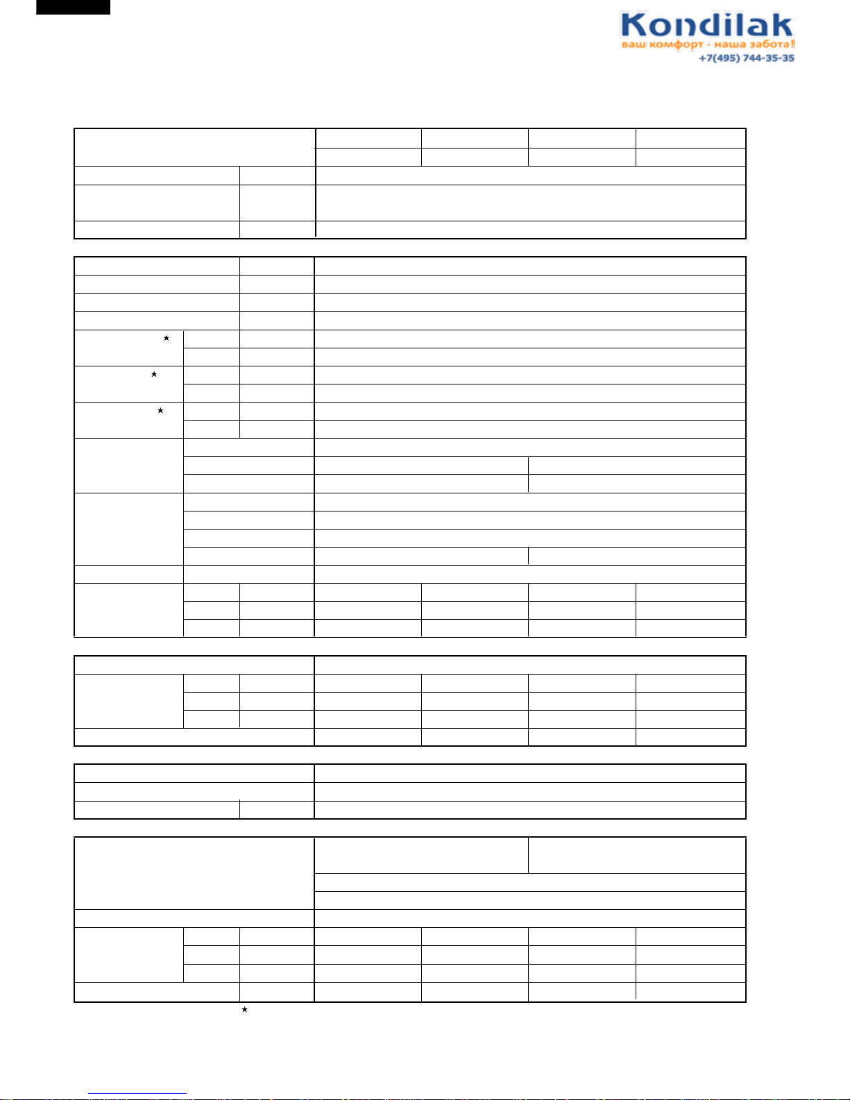
SPECIFICATIONS
ITEMS
INDOOR UNIT OUTDOOR UNIT INDOOR UNIT OUTDOOR UNIT
AY-A07BE AE-A07BE AY-A07BE-C AE-A07BE-C
Cooling capacity kW 2.1
Heat pump kW 2.4
Heating capacity
Moisture removal Liters/h 0.7
Electrical data
Phase – Single
Rated frequency Hz 50
Rated voltage range V 198 to 264
Rated voltage V 220 - 240
Rated current Cool A 3.1 - 3.0
Heat A 2.9 - 2.8
Rated input Cool W 650 - 690
Heat W 600 - 640
Power factor Cool % 95 - 96
Heat % 94 - 95
Compressor Type Hermetically sealed rotary type
Model QK134PA13A RH135VHST
Oil charge 300cc (SUNISO 4GSI) 300cc (DIAMOND MS56)
Refrigerant system
Evaporator Louver fin and Bare tube type
Condenser Corrugate fin and Grooved tube type
Control Capillary tube
Refrigerant volume 700g 650g
De-Ice system Micro computercontroled reverse systyem
Noise level High dB(A) 33 43 33 43
(at cooling) Med. dB(A) 29 – 29 –
Low dB(A) 27 – 27 –
Fan system
Drive Direct drive
Air flow quantity High m3/min. 7.2 21 7.2 21
Med. m3/min. 6.0 – 6.0 –
Low m3/min. 4.8 – 4.8 –
Fan Cross flow fan Propeller fan Cross flow fan Propeller fan
Connections
Refrigerant coupling Flare type
Refrigerant tube size Gas, Liquid 3/8", 1/4"
Drain piping mm O.D ø 18
Others
Safety device Compressor: Overload protector Compressor: Overload protector
(Internal)
Fan motor: Thermal fuse
Fuse, Micro computer control
Air filters Polypropylene net (Washable)
Net dimensions Width mm 815 720 815 720
Height mm 278 535 278 535
Depth mm 198 236 198 236
Net weight kg 9 30 9 30
Note: The condition of star( ) marked item are 'ISO5151' : 1994(E), condition T1.
Page 3
AH-A07BE-C/09BE-C
AH-A07BE/09BE/12BE
AY-A07BE-C/09BE-C
AY-A07BE/09BE/12BE
3
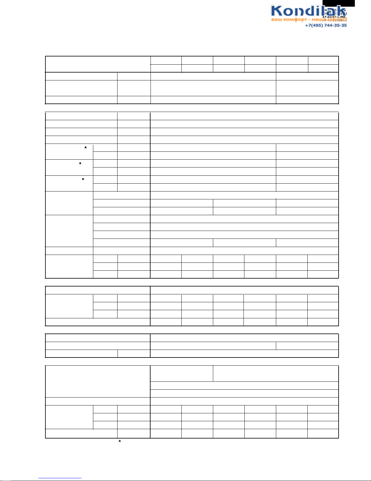
Overload
ITEMS
INDOOR UNIT
OUTDOOR UNIT
INDOOR UNIT
OUTDOOR UNIT
INDOOR UNIT
OUTDOOR UNIT
AY-A09BE AE-A09BE AY-A09BE-C AE-A09BE-C AY-A12BE AE-A12BE
Cooling capacity kW 2.64 3.5
Heat pump kW 3.1 4.0
Heating capacity
Moisture removal Liters/h 0.8 1.2
Electrical data
Phase – Single
Rated frequency Hz 50
Rated voltage range V 198 to 264
Rated voltage V 220 - 240
Rated current Cool A 3.8 - 3.6 5.0 - 4.8
Heat A 3.7 - 3.5 5.0 - 4.8
Rated input Cool W 820 - 850 1090 - 1120
Heat W 810 - 840 1080 - 1120
Power factor Cool % 98 - 98 99 - 97
Heat % 100 - 100 98 - 97
Compressor Type Hermetically sealed rotary type
Model QK164PA13A RH165VHET RH207VHET
Oil charge
300cc (SUNISO 4GSI) 300cc (DIAMOND MS56) 520cc (DIAMOND MS56)
Refrigerant system
Evaporator Louver fin and Grooved tube type
Condenser Corrugate fin and Grooved tube type
Control Capillary tube
Refrigerant volume 740g 690g 970g
De-Ice system Micro computercontroled reverse systyem
Noise level High dB(A) 36 43 36 43 38 48
(at cooling) Med. dB(A) 32 – 32 – 33 –
Low dB(A) 27 – 27 – 29 –
Fan system
Drive Direct drive
Air flow quantity High m3/min. 8.6 28 8.6 28 9.3 30
Med. m3/min. 6.8 – 6.8 – 8.4 –
Low m3/min. 5.3 – 5.3 – 7.4 –
Fan
Cross flow fan Propeller fan Cross flow fan Propeller fan Cross flow fan Propeller fan
Connections
Refrigerant coupling Flare type
Refrigerant tube size Gas, Liquid 3/8", 1/4" 1/2", 1/4"
Drain piping mm O.D ø 18
Others
Safety device Compressor: Compressor: Overload protector (Internal)
Overload protector
Fan motor: Thermal fuse
Fuse, Micro computer control
Air filters Polypropylene net (Washable)
Net dimensions Width mm 815 780 815 780 815 780
Height mm 278 540 278 540 278 540
Depth mm 198 269 198 269 198 269
Net weight kg 9 34 9 34 10 39
Note: The condition of star( ) marked item are 'ISO5151' : 1994(E), condition T1.
Page 4
4
AH-A07BE-C/09BE-C
AH-A07BE/09BE/12BE
AY-A07BE-C/09BE-C
AY-A07BE/09BE/12BE
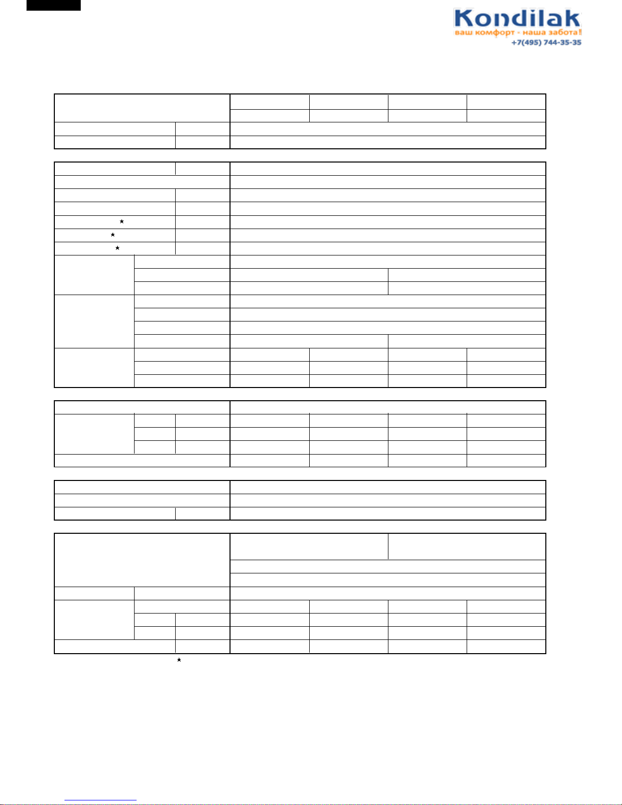
ITEMS
INDOOR UNIT OUTDOOR UNIT INDOOR UNIT OUTDOOR UNIT
AH-A07BE AU-A07BE AH-A07BE-C AU-A07BE-C
Cooling capacity kW 2.1
Moisture removal Liters/h 0.7
Electrical data
Phase – Single
Rated frequency Hz 50
Rated voltage range V 198 to 264
Rated voltage V 220 - 240
Rated current A 3.1 - 3.0
Rated input W 650 - 690
Power factor % 95 - 96
Compressor Type Hermetically sealed rotary type
Model QK134PA13A RH130VHST
Oil charge
300cc (SUNISO 4GSI) 300cc (
DIAMOND MS 56
)
Refrigerant system
Evaporator Louver fin and Bare tube type
Condenser Louver fin and Bare tube type
Control Capillary tube
Refrigerant volume 480g 470g
Noise level High dB(A) 33 43 33 43
(at cooling) Med. dB(A) 29 – 29 –
Low dB(A) 27 – 27 –
Fan system
Drive Direct drive
Air flow quantity High m3/min. 7.2 20 7.2 20
Med. m3/min. 6.0 – 6.0 –
Low m3/min. 4.8 – 4.8 –
Fan Cross flow fan Propeller fan Cross flow fan Propeller fan
Connections
Refrigerant coupling Flare type
Refrigerant tube size Gas, Liquid 3/8", 1/4"
Drain piping mm O.D ø 18
Others
Safety device Compressor: Overload protector Compressor: Overload protector
(Internal)
Fan motor: Thermal fuse
Fuse, Micro computer control
Air filters Polypropylene net (Washable)
Net dimensions Width mm 815 720 815 720
Height mm 278 535 278 535
Depth mm 198 236 198 236
Net weight kg 9 29 9 29
Note: The condition of star( ) marked item are 'ISO5151' : 1994(E), condition T1.
Page 5
AH-A07BE-C/09BE-C
AH-A07BE/09BE/12BE
AY-A07BE-C/09BE-C
AY-A07BE/09BE/12BE
5
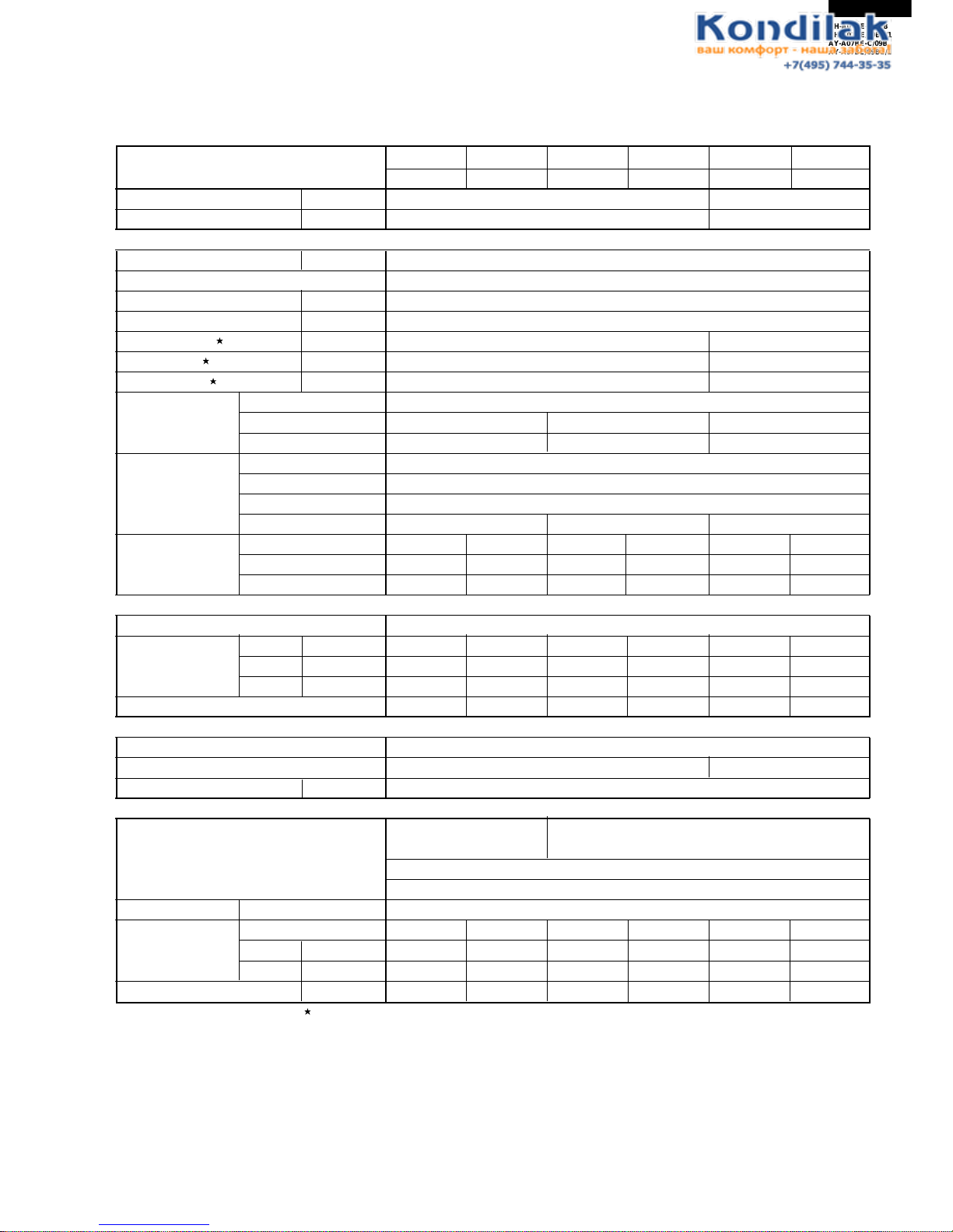
ITEMS
INDOOR UNIT
OUTDOOR UNIT
INDOOR UNIT
OUTDOOR UNIT
INDOOR UNIT
OUTDOOR UNIT
AH-A09BE AU-A09BE AH-A09BE-C AU-A09BE-C AH-A12BE AU-A12BE
Cooling capacity kW 2.64 3.5
Moisture removal Liters/h 0.8 1.2
Electrical data
Phase – Single
Rated frequency Hz 50
Rated voltage range V 198 to 264
Rated voltage V 220 - 240
Rated current A 3.8 - 3.6 5.0 - 4.8
Rated input W 820 - 850 1090 - 1120
Power factor % 98 - 98 99 - 97
Compressor Type Hermetically sealed rotary type
Model QK164PA13A RH154VHST RH207VHET
Oil charge
300cc (SUNISO 4GSI) 300cc (DIAMOND MS56) 520cc (DIAMOND MS56)
Refrigerant system
Evaporator Louver fin and Grooved tube type
Condenser Louver fin and Grooved tube type
Control Capillary tube
Refrigerant volume 550g 560g 870g
Noise level High dB(A) 36 43 36 43 38 48
(at cooling) Med. dB(A) 32 – 32 – 33 –
Low dB(A) 27 – 27 – 29 –
Fan system
Drive Direct drive
Air flow quantity High m3/min. 8.6 28 8.6 28 9.3 30.0
Med. m3/min. 6.8 – 6.8 – 8.4 –
Low m3/min. 5.3 – 5.3 – 7.4 –
Fan
Cross flow fan Propeller fan Cross flow fan Propeller fan Cross flow fan Propeller fan
Connections
Refrigerant coupling Flare type
Refrigerant tube size Gas, Liquid 3/8", 1/4" 1/2", 1/4"
Drain piping mm O.D ø 18
Others
Safety device
Compressor: Overload protector Compressor: Overload protector
(Internal)
Fan motor: Thermal fuse
Fuse, Micro computer control
Air filters Polypropylene net (Washable)
Net dimensions Width mm 815 780 815 780 815 780
Height mm 278 540 278 540 278 540
Depth mm 198 269 198 269 198 269
Net weight kg 9 33 9 33 10 38
Note: The condition of star( ) marked item are 'ISO5151' : 1994(E), condition T1.
Page 6

6
AH-A07BE-C/09BE-C
AH-A07BE/09BE/12BE
AY-A07BE-C/09BE-C
AY-A07BE/09BE/12BE
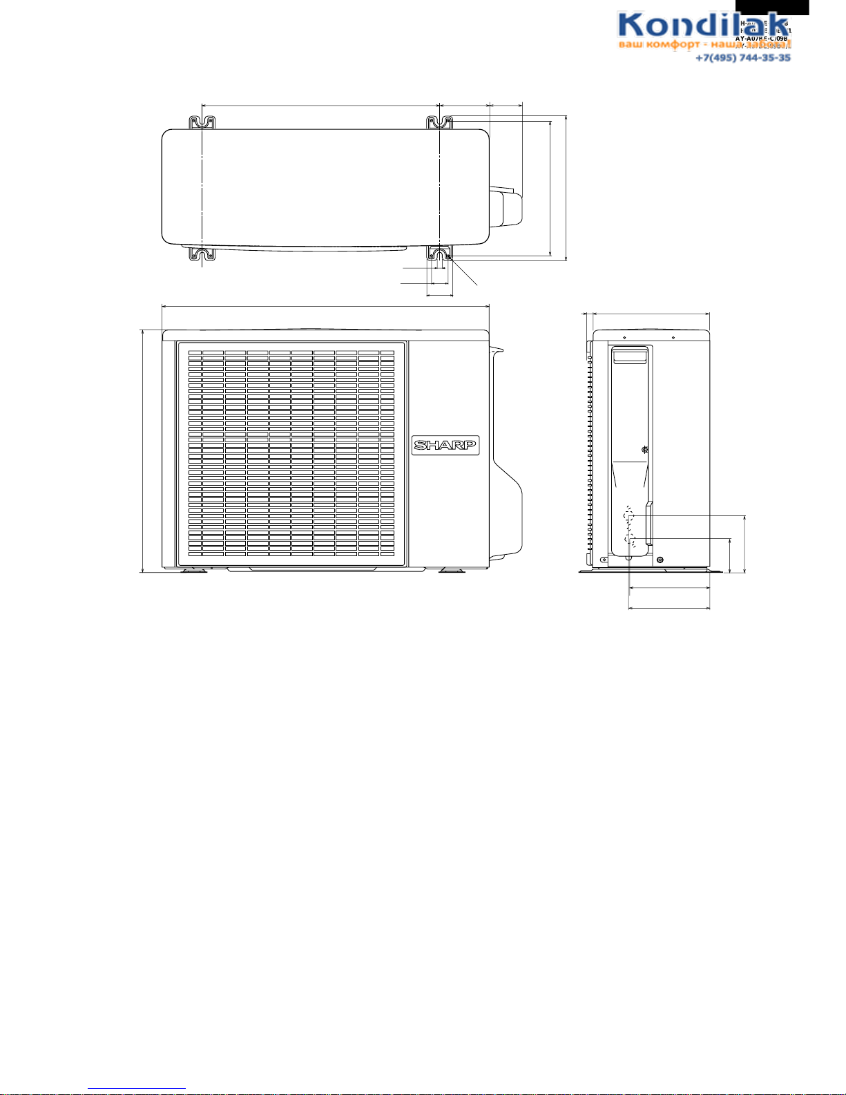
EXTERNAL DIMENSIONS
Figure E-1. INDOOR UNIT
Figure E-2. OUTDOOR UNIT FOR AE-A07BE/AE-A07BE-C AND AU-A07BE/AU-A07BE-C
Length unit (mm)
815
278
198
1100
Remote controller
58
18.5
22
140
INVERTER AIR CONDITIONER
430
720
775
143
55
245
535
278
236
228
20˚
58
Page 7
AH-A07BE-C/09BE-C
AH-A07BE/09BE/12BE
AY-A07BE-C/09BE-C
AY-A07BE/09BE/12BE
7
Figure E-3. OUTDOOR UNIT FOR AE-A09BE/AE-A09BE-C/A12BE AND AU-A09BE/AU-A09BE-C/A12BE
269
179.5
182.5
136
81
780
70
540
310
335
540
12
37.5
4.5
58
158
16
Page 8
8
AH-A07BE-C/09BE-C
AH-A07BE/09BE/12BE
AY-A07BE-C/09BE-C
AY-A07BE/09BE/12BE
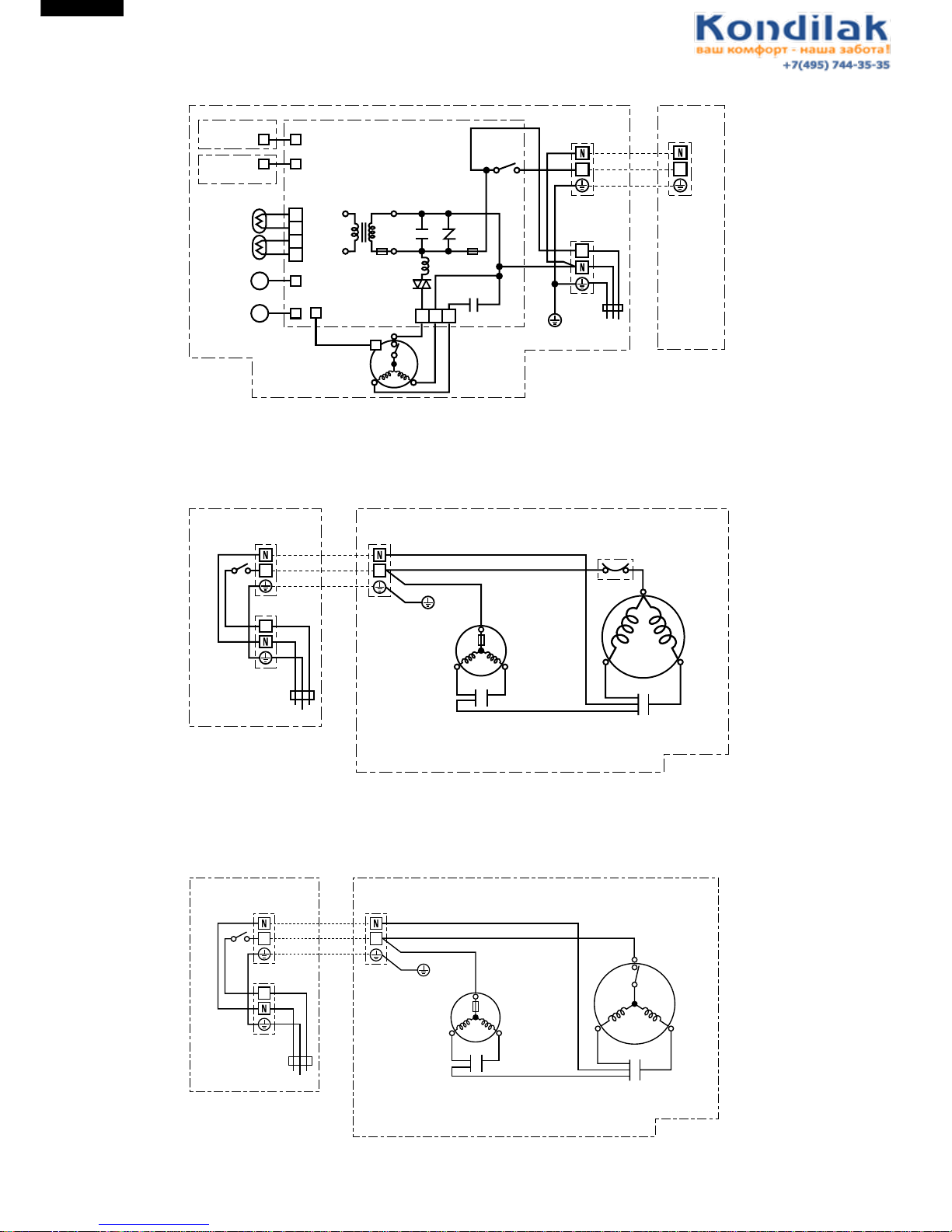
Figure W-1. Wiring Diagram for AH-A07BE/A07BE-C/A09BE/A09BE-C/A12BE
WIRING DIAGRAMS
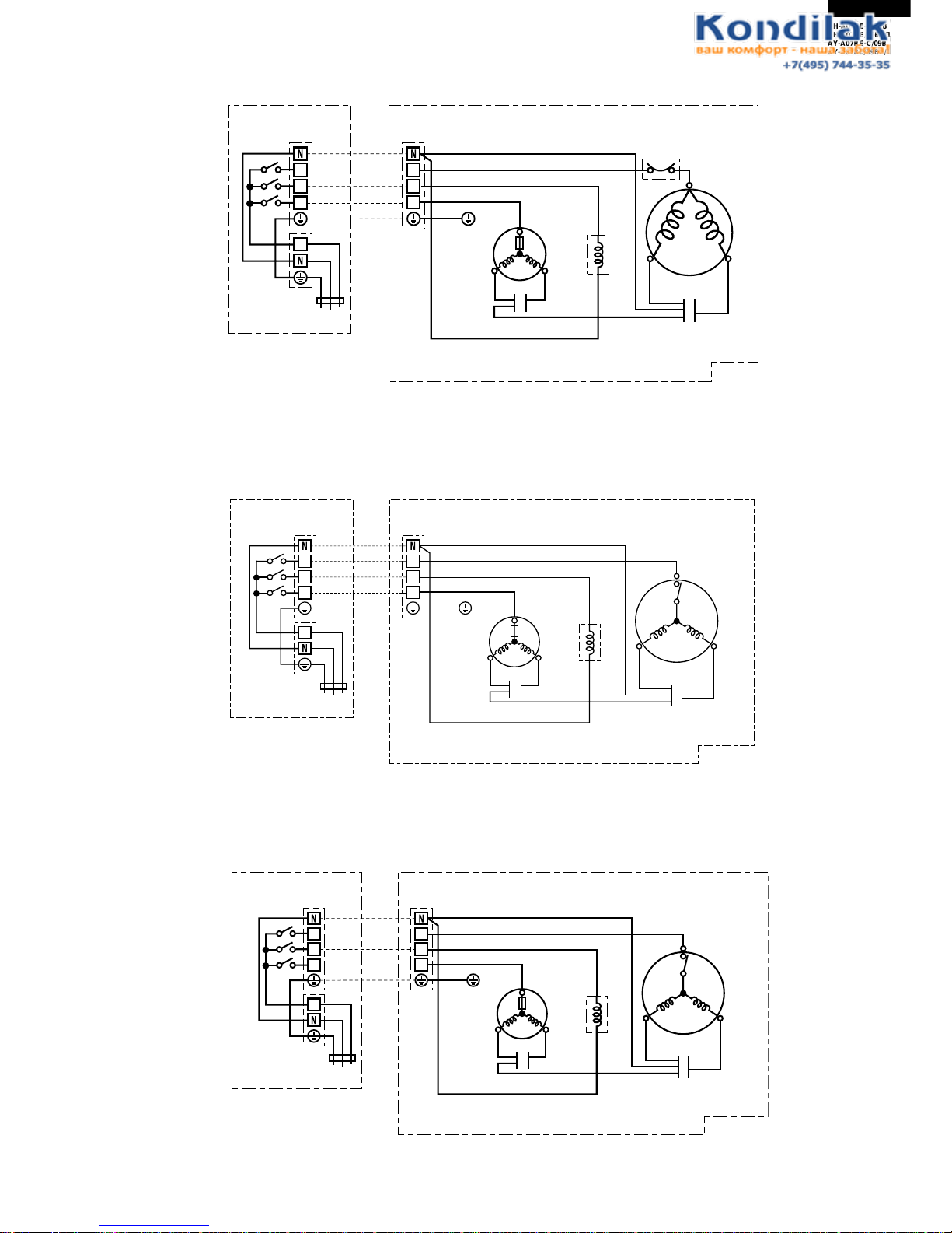
Figure W-2. Wiring Diagram for AU-A07BE
Figure W-3. Wiring Diagram for AU-A07BE-C
INTERNAL
THERMOSTAT
TRANSFORMER
CONTROL BOARD UNIT
WPE1
IN
TEMP.FUSE
L
SSR
EVAPORATOR
BLBK
CN1
R
OUTDOOR
UNIT
TERMINAL
BOARD
FAN MOTOR
CAPACITOR
FAN
MOTOR
UNIT TO UNIT CORD
BK
BL
BR
: BLACK
: BLUE
: BROWN
R
G(Y
)
: RED
: GREEN-YELLOW
THERMISTOR
(PIPE TEMP.)
THERMISTOR
(ROOM TEMP.)
LOWER
LOUVER MOTOR
UPPER
LOUVER MOTOR
M
CN2
CN5
CN4
BCN2
BCN202
BCN201
RY1
BR
BR
BCN1
1
2
3
4
DISPLAY
UNIT
RECEIVER
UNIT
M
CN3
1 3 5
OUT
C1 NR1
3A
250V
INDOOR UNIT
BK
BL
BL
BL
G(Y
)
G(Y
)
TERMINAL BOARD 1
TERMINAL BOARD 2
POWER
SUPPLY
R.P.M SIGNAL
11
1
(N)
400(430)V 2µF
INTERNAL
THERMAL
FUSE
MOTOR PROTECTOR
OUTDOOR UNIT
TERMINAL BOARD
RUNNING
CAPACITOR
370V 25µF
FAN MOTOR
FAN MOTOR
CAPACITOR
400(450)V 1.5µF
COMPRESSOR MOTOR
C
BK
BL
BK
R
S
W
R
R
BL
CONTROL BOX
BK BL
UNIT TO UNIT CORD
BK
BR
R
BL
: BLACK
: BROWN
: RED
: BLUE
W
G(Y)
: WHITE
: GREEN YELLOW
1 1
INDOOR UNIT
TERMINAL BOARD 1
BR
BL
G(Y
)
BR
BL
G(Y
)
G(Y
)
TERMINAL BOARD 2
POWER SUPPLY
1
INTERNAL
THERMAL
FUSE
INTERNAL
MOTOR
PROTECTOR
OUTDOOR UNIT
TERMINAL BOARD
RUNNING
CAPACITOR
400V 25µF
FAN MOTOR
FAN MOTOR
CAPACITOR
400(450)V 1.5µF
COMPRESSOR MOTOR
C
BL
BK
R
S
W
R
R
BL
CONTROL BOX
BK BL
UNIT TO UNIT CORD
BK
BR
R
BL
: BLACK
: BROWN
: RED
: BLUE
W
G(Y)
: WHITE
: GREEN YELLOW
1 1
INDOOR UNIT
TERMINAL BOARD 1
BR
BL
G(Y
)
BR
BL
G(Y
)
G(Y
)
TERMINAL BOARD 2
POWER SUPPLY
1
Page 9
AH-A07BE-C/09BE-C
AH-A07BE/09BE/12BE
AY-A07BE-C/09BE-C
AY-A07BE/09BE/12BE
9
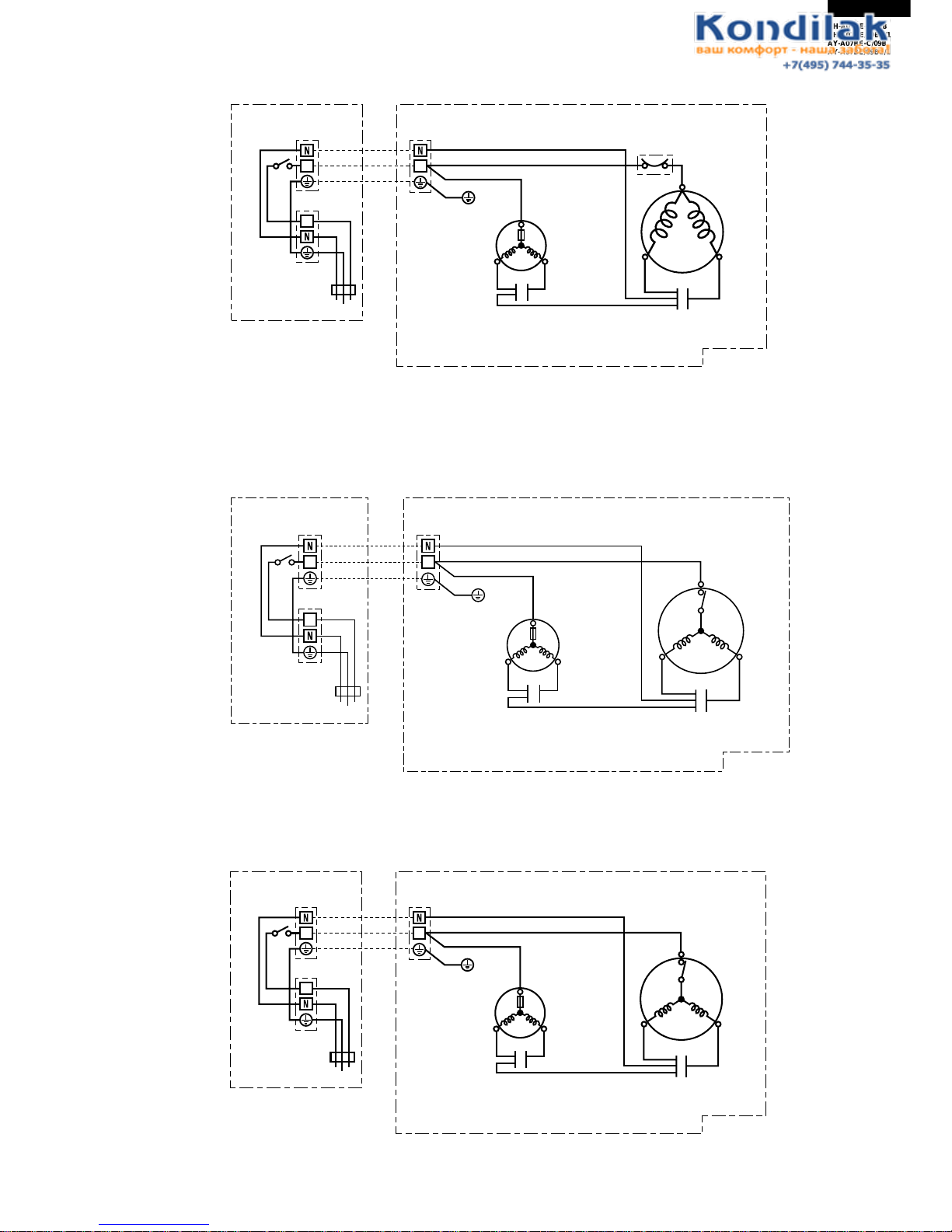
Figure W-4. Wiring Diagram for AU-A09BE
Figure W-5. Wiring Diagram for AU-A09BE-C
Figure W-6. Wiring Diagram for AU-A12BE
INTERNAL
THERMAL
FUSE
MOTOR PROTECTOR
OUTDOOR UNIT
TERMINAL BOARD
RUNNING
CAPACITOR
400V 30µF
FAN MOTOR
FAN MOTOR
CAPACITOR
400(450)V 1.5µF
COMPRESSOR MOTOR
C
BK
BL
BK
R
S
W
R
R
BL
CONTROL BOX
BK BL
UNIT TO UNIT CORD
BK
BR
R
BL
: BLACK
: BROWN
: RED
: BLUE
W
G(Y)
: WHITE
: GREEN YELLOW
1 1
INDOOR UNIT
TERMINAL BOARD 1
BR
BL
G(Y
)
BR
BL
G(Y
)
G(Y
)
TERMINAL BOARD 2
POWER SUPPLY
1
INTERNAL
THERMAL
FUSE
INTERNAL
MOTOR
PROTECTOR
OUTDOOR UNIT
TERMINAL BOARD
RUNNING
CAPACITOR
400V 25µF
FAN MOTOR
FAN MOTOR
CAPACITOR
400(450)V 1.5µF
COMPRESSOR MOTOR
C
BL
BK
R
S
W
R
R
BL
CONTROL BOX
BK BL
UNIT TO UNIT CORD
BK
BR
R
BL
: BLACK
: BROWN
: RED
: BLUE
W
G(Y)
: WHITE
: GREEN YELLOW
1 1
INDOOR UNIT
TERMINAL BOARD 1
BR
BL
G(Y
)
BR
BL
G(Y
)
G(Y
)
TERMINAL BOARD 2
POWER SUPPLY
1
INTERNAL
THERMAL
FUSE
INTERNAL
MOTOR
PROTECTOR
OUTDOOR UNIT
TERMINAL BOARD
RUNNING
CAPACITOR
400V 30µF
FAN MOTOR
FAN MOTOR
CAPACITOR
400(450)V 2µF
COMPRESSOR MOTOR
C
BL
BK
R
S
W
R
R
BL
CONTROL BOX
BK BL
UNIT TO UNIT CORD
BK
BR
R
BL
: BLACK
: BROWN
: RED
: BLUE
W
G(Y)
: WHITE
: GREEN YELLOW
1 1
INDOOR UNIT
TERMINAL BOARD 1
BR
BL
G(Y
)
BR
BL
G(Y
)
G(Y
)
TERMINAL BOARD 2
POWER SUPPLY
1
Page 10
10
AH-A07BE-C/09BE-C
AH-A07BE/09BE/12BE
AY-A07BE-C/09BE-C
AY-A07BE/09BE/12BE
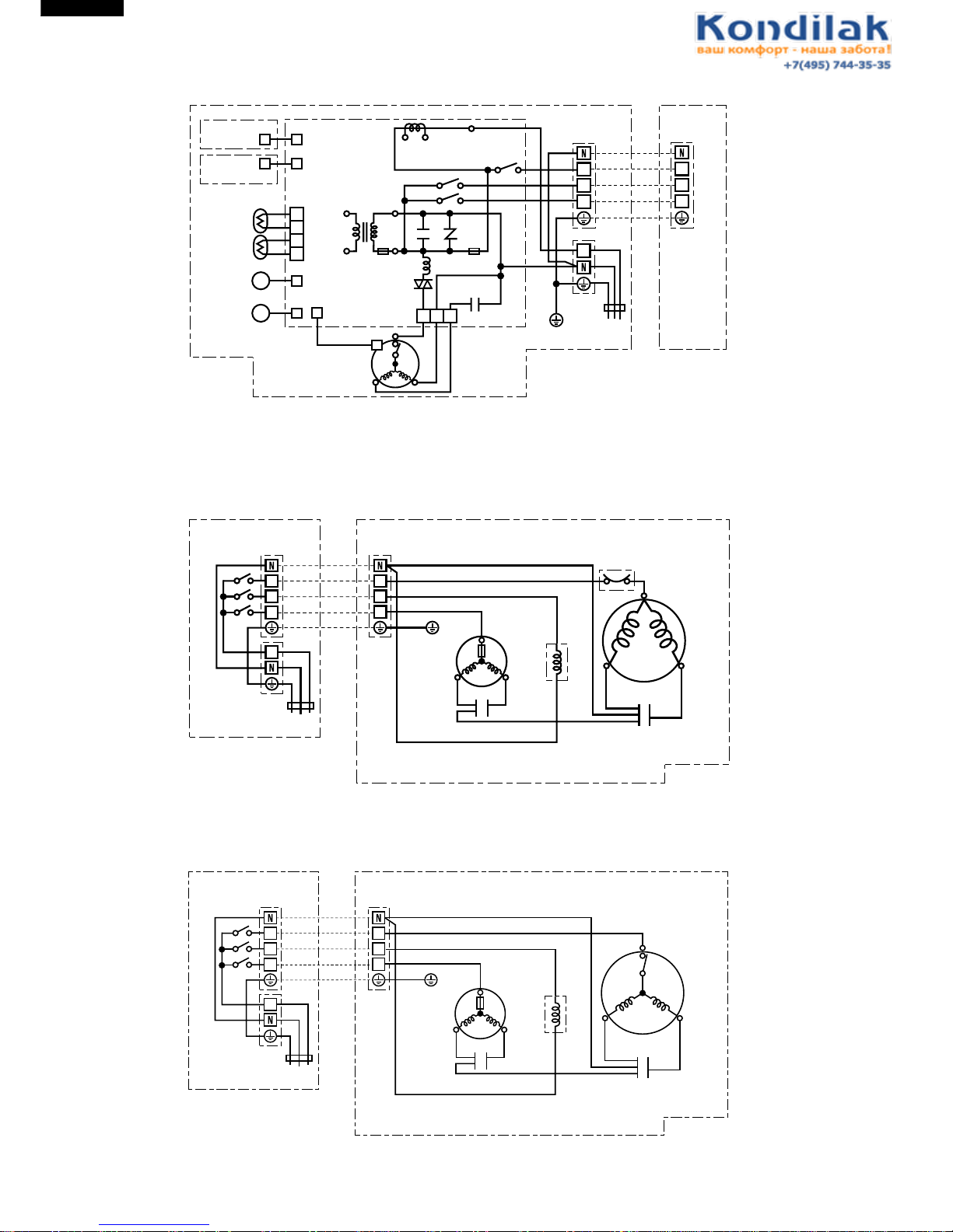
Figure W-7. Wiring Diagram for AY-A07BE/A07BE-C/A09BE/A09BE-C/A12BE
Figure W-8. Wiring Diagram for AE-A07BE
Figure W-9. Wiring Diagram for AE-A07BE-C
INTERNAL
THERMOSTAT
TRANSFORMER
CONTROL BOARD UNIT
WPE1
TEMP.FUSE
L
SSR
EVAPORATOR
BLBK
CN1
R
OUTDOOR
UNIT
TERMINAL
BOARD
FAN MOTOR
CAPACITOR
FAN
MOTOR
UNIT TO UNIT CORD
BK
BL
BR
: BLACK
: BLUE
: BROWN
O
P
R
G(Y)
: ORANGE
: PURPLE
: RED
: GREEN-YELLOW
THERMISTOR
(PIPE TEMP.)
THERMISTOR
(ROOM TEMP.)
LOWER
LOUVER MOTOR
UPPER
LOUVER MOTOR
M
CN2
CN5
CN4
BCN2
BCN202
BCN201
RY2
RY1
RY3
BR
BCN1
1
2
3
4
DISPLAY
UNIT
RECEIVER
UNIT
M
CN3
1 3 5
C.T.
OUT
T1
C1 NR1
3A
250V
INDOOR UNIT
P
BK
BL
BL
BR
BL
O
G(Y
)
G(Y
)
TERMINAL BOARD 1
TERMINAL BOARD 2
POWER
SUPPLY
R.P.M SIGNAL
1
2
3
1
2
3
1
(A)
(B)
(N)
400(430)V 2µF
INTERNAL
THERMAL
FUSE
MOTOR PROTECTOR
OUTDOOR UNIT
TERMINAL BOARD
RUNNING
CAPACITOR
370V 25µF
FAN MOTOR
VALVE
COIL
FAN MOTOR
CAPACITOR
400(450)V 1.5µF
COMPRESSOR MOTOR
C
BK
BK
BL
R
S
W
R
R
BL
CONTROL BOX
BK
BK
BK
BL
UNIT TO UNIT CORD
BK
BR
R
BL
: BLACK
: BROWN
: RED
: BLUE
W
G(Y)
: WHITE
: GREEN YELLOW
1
2
1
2
3
INDOOR UNIT
TERMINAL
BOARD 1
POWER SUPPLY
BL
BR
BL
BR
G(Y
)
G(Y
)
G(Y
)
TERMINAL BOARD 2
3
1
INTERNAL
THERMAL
FUSE
INTERNAL
MOTOR
PROTECTOR
OUTDOOR UNIT
TERMINAL BOARD
RUNNING
CAPACITOR
400V 25µF
FAN MOTOR
VALVE
COIL
FAN MOTOR
CAPACITOR
400(450)V 1.5µF
COMPRESSOR MOTOR
C
BK
BK
BL
R
S
W
R
R
BL
CONTROL BOX
BK
BK
BL
UNIT TO UNIT CORD
BK
BR
R
BL
: BLACK
: BROWN
: RED
: BLUE
W
G(Y)
: WHITE
: GREEN YELLOW
CB574
1
2
1
2
3
INDOOR UNIT
TERMINAL
BOARD 1
POWER SUPPLY
BL
BR
BL
BR
G(Y
)
G(Y
)
G(Y
)
TERMINAL BOARD 2
3
1
Page 11
AH-A07BE-C/09BE-C
AH-A07BE/09BE/12BE
AY-A07BE-C/09BE-C
AY-A07BE/09BE/12BE
11
Figure W-10. Wiring Diagram for AE-A09BE
Figure W-11. Wiring Diagram for AE-A09BE-C
Figure W-12. Wiring Diagram for AE-A12BE
INTERNAL
THERMAL
FUSE
MOTOR PROTECTOR
OUTDOOR UNIT
TERMINAL BOARD
RUNNING
CAPACITOR
400V 30µF
FAN MOTOR
VALVE
COIL
FAN MOTOR
CAPACITOR
400(450)V 1.5µF
COMPRESSOR MOTOR
C
BK
BK
BL
R
S
W
R
R
BL
CONTROL BOX
BK
BK
BK
BL
UNIT TO UNIT CORD
BK
BR
R
BL
: BLACK
: BROWN
: RED
: BLUE
W
G(Y)
: WHITE
: GREEN YELLOW
1
2
1
2
3
INDOOR UNIT
TERMINAL
BOARD 1
POWER SUPPLY
BL
BR
BL
BR
G(Y
)
G(Y
)
G(Y
)
TERMINAL BOARD 2
3
1
INTERNAL
THERMAL
FUSE
INTERNAL
MOTOR
PROTECTOR
OUTDOOR UNIT
TERMINAL BOARD
RUNNING
CAPACITOR
400V 25µF
FAN MOTOR
VALVE
COIL
FAN MOTOR
CAPACITOR
400(450)V 1.5µF
COMPRESSOR MOTOR
C
BK
BK
BL
R
S
W
R
R
BL
CONTROL BOX
BK
BK
BL
UNIT TO UNIT CORD
BK
BR
R
BL
: BLACK
: BROWN
: RED
: BLUE
W
G(Y)
: WHITE
: GREEN YELLOW
CB572
1
2
1
2
3
INDOOR UNIT
TERMINAL
BOARD 1
POWER SUPPLY
BL
BR
BL
BR
G(Y
)
G(Y
)
G(Y
)
TERMINAL BOARD 2
3
1
INTERNAL
THERMAL
FUSE
INTERNAL
MOTOR
PROTECTOR
OUTDOOR UNIT
TERMINAL BOARD
RUNNING
CAPACITOR
400V 30µF
FAN MOTOR
VALVE
COIL
FAN MOTOR
CAPACITOR
400(450)V 2µF
COMPRESSOR MOTOR
C
BK
BK
BL
R
S
W
R
R
BL
CONTROL BOX
BK
BK
BL
UNIT TO UNIT CORD
BK
BR
R
BL
: BLACK
: BROWN
: RED
: BLUE
W
G(Y)
: WHITE
: GREEN YELLOW
1
2
1
2
3
INDOOR UNIT
TERMINAL
BOARD 1
POWER SUPPLY
BL
BR
BL
BR
G(Y
)
G(Y
)
G(Y
)
TERMINAL BOARD 2
3
1
Page 12
12
AH-A07BE-C/09BE-C
AH-A07BE/09BE/12BE
AY-A07BE-C/09BE-C
AY-A07BE/09BE/12BE
ELECTRICAL PARTS
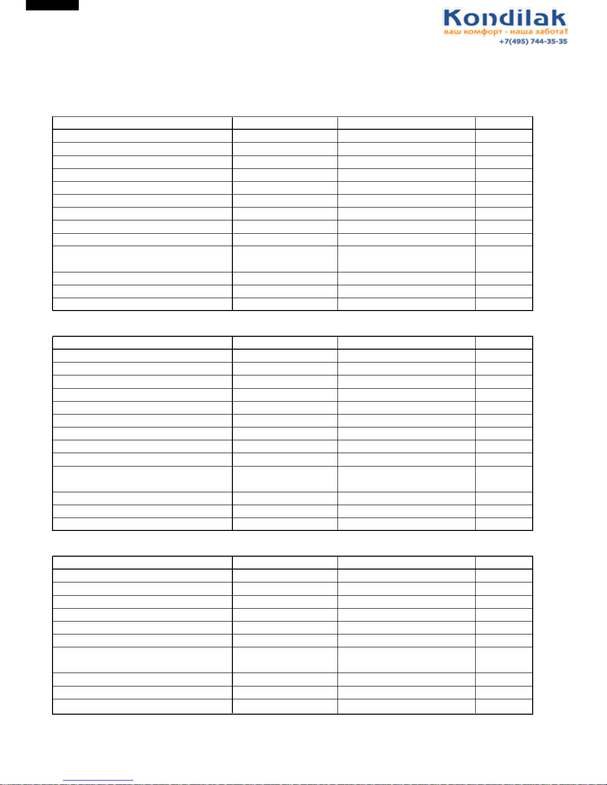
For Models AY-A07BE/A07BE-C, AH-A07BE/A07BE-C, AE-A07BE/A07BE-C, AU-A07BE and AU-A07BE-C
DESCRIPTION MODEL REMARKS SITE
Compressor QK134PA13A 220 - 240V, 50Hz, 620W
AE/AU-A07BE
Compressor RH135VHST 220 - 240V, 50Hz, 650W AE-A07BE-C
Compressor RH130VHST 220 - 240V, 50Hz, 650W AU-A07BE-C
Indoor fan motor ML-A915 220 - 240V, 50Hz AY, AH
Outdoor fan motor ML-A592 220 - 240V, 50Hz AE, AU
Indoor fan motor capacitor – 400V, 2µF AY, AH
Outdoor fan motor capacitor – 400V, 1.5µF AE, AU
Running capacitor – 370V, 25µF
AE/AU-A07BE
Running capacitor – 400V, 25µF
AE/AU-A07BE-C
Transformer – Primary; AC 230V, 50Hz AY, AH
Secondary; AC16.7V, 50Hz
Fuse – 250V, 3A AY, AH
Reverse valve VK1100B, 1400B – AE
Reverse valve coil – 220 - 240V, 50/60Hz AE
For Models AY-A09BE/A09BE-C, AH-A09BE/A09BE-C, AE-A09BE/A09BE-C, AU-A09BE and AU-A09BE-C
DESCRIPTION MODEL REMARKS SITE
Compressor QK164PA13A 220 - 240V, 50Hz, 780W
AE/AU-A09BE
Compressor RH165VHET 220 - 240V, 50Hz, 800W
AE-A09BE
Compressor RH154VHST 220 - 240V, 50Hz, 750W
AU-A09BE
Indoor fan motor ML-A915 220 - 240V, 50Hz AY, AH
Outdoor fan motor ML-A916
220-240V,50Hz 220-230V,60Hz
AE, AU
Indoor fan motor capacitor – 400V, 2µF AY, AH
Outdoor fan motor capacitor – 400V, 1.5µF AE, AU
Running capacitor – 400V, 30µF
AE/AU-A09BE
Running capacitor – 400V, 25µF
AE/AU-A09BE-C
Transformer – Primary; AC 230V, 50Hz AY, H
Secondary; AC16.7V, 50Hz
Fuse – 250V, 3A AY, AH
Reverse valve VK1100B, 1400B – AE
Reverse valve coil – 220 - 240V, 50/60Hz AE
For Model AY-A12BE, AH-A12BE , AE-A12BE and AU-A12BE
DESCRIPTION MODEL REMARKS SITE
Compressor RH207VHET 220 - 240V, 50Hz, 1000W AE, AU
Indoor fan motor ML-A915 220 - 240V, 50Hz AY, AH
Outdoor fan motor ML-A917
220-240V,50Hz 220-230V,60Hz
AE, AU
Indoor fan motor capacitor – 400V, 2µF AY, AH
Outdoor fan motor capacitor – 400V, 2µF AE, AU
Running capacitor – 400V, 30µF AE, AU
Transformer – Primary; AC 230V, 50Hz AY, AH
Secondary; AC16.7V, 50Hz
Fuse – 250V, 3A AY, AH
Reverse valve VK2100B, 2400B – AE
Reverse valve coil – 220 - 240V, 50/60Hz AE
Page 13
AH-A07BE-C/09BE-C
AH-A07BE/09BE/12BE
AY-A07BE-C/09BE-C
AY-A07BE/09BE/12BE
13
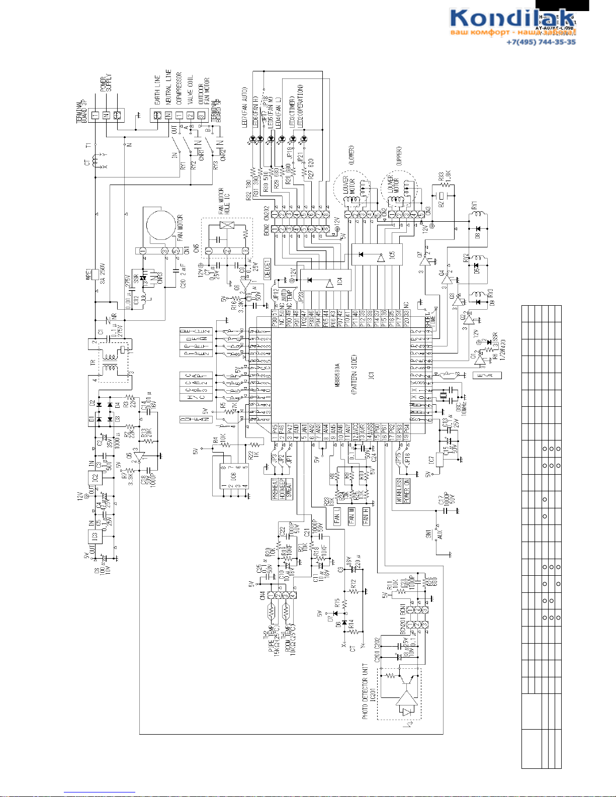
Figure L-1. Electronic Control Circuit Diagram for AY-A07BE/AY-A07BE-C/A09BE/A09BE-C/A12BE
MICROCOMPUTER CONTROL SYSTEM
AY-A07BE/A07BE-C
AY-A09BE/A09BE-C
AY-A12BE
PART CODE
DPWBFA210JBKZ
DPWBFA208JBKZ
DPWBFA211JBKZ
P47
SWEAT
JP1
NONE
NONE
NONE
P46
HOT KEEP
JP2
NONE
NONE
NONE
P45
REHEAT
JP3
NONE
NONE
NONE
P41
H/C
JP4
NONE
NONE
NONE
P40
CAP3
JP5
P37
CAP2
JP6
NONE
P36
CAP1
JP7
NONE
P34
PIPE 2
JP8
P33
PIPE 1
JP9
NONE
NONE
NONE
P32
D FAN
JP10
NONE
NONE
NONE
P31
DEICE 2
JP11
NONE
NONE
P30
DEICE 1
JP12
NONE
NONE
P27
EUROPE/ASIA
JP13
NONE
NONE
NONE
P44
OUT FAN
P63
WIRELESS
JP15JP14
P64
POWER ON
JP16
NONE
NONE
NONE
P01
SWEAT
JP23
NONE
NONE
NONE
AN5
FAN L
R8
15K
15K
15K
AN6
FAN M
R9
15K
15K
NONE
AN7
FAN H
15K
15K
15K
15K
CT
R12
6.8KF
6.8KF
6.8KF
CT
R14
2.7KF
2.7KF
2.7KF
CT
R15
1KF
1KF
1KF
Page 14
14
AH-A07BE-C/09BE-C
AH-A07BE/09BE/12BE
AY-A07BE-C/09BE-C
AY-A07BE/09BE/12BE
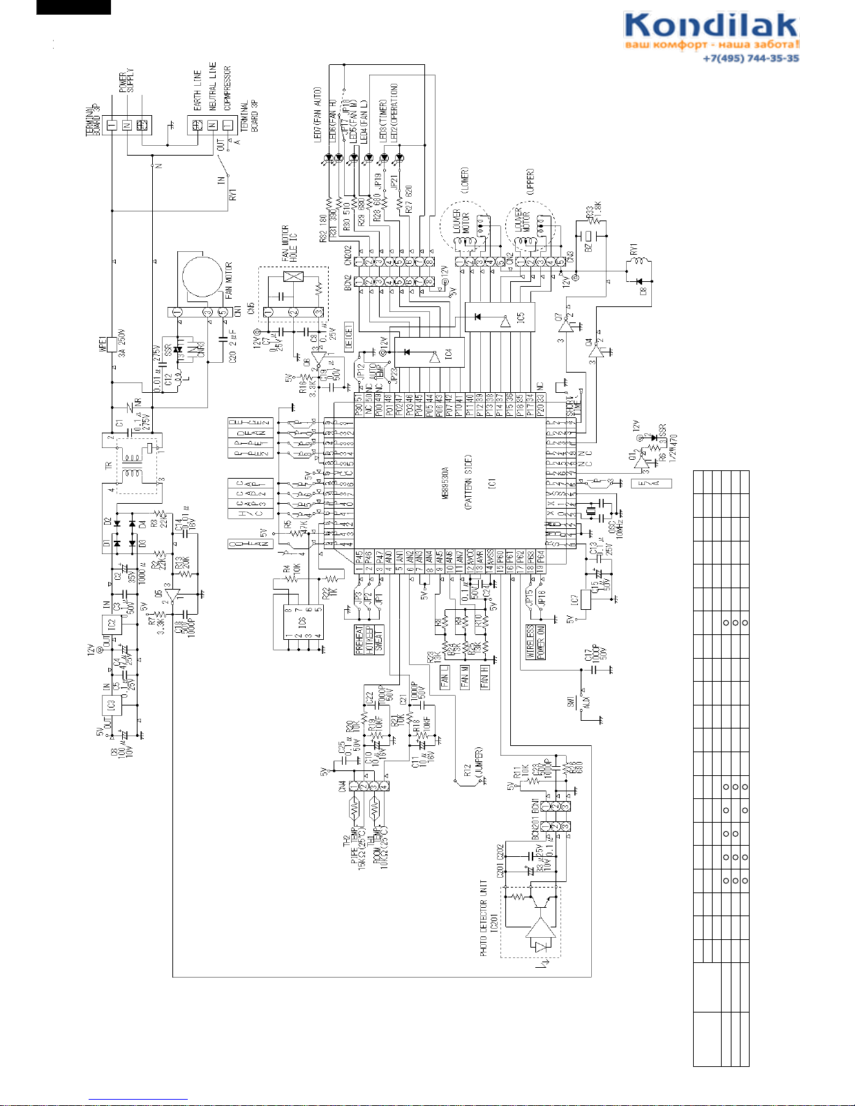
Figure L-2. Electronic Control Circuit Diagram for AH-A07BE/A07BE-C/A09BE/A09BE-C/A12BE
AH-A07BE/07BE-C
AH-A09BE/A09BE-C
AH-A12BE
PART CODE
DPWBFA212JBKZ
DPWBFA209JBKZ
DPWBFA213JBKZ
P47
SWEAT
JP1
NONE
NONE
NONE
P46
HOT KEEP
JP2
NONE
NONE
NONE
P45
REHEAT
JP3
NONE
NONE
NONE
P41
H/C
JP4
P40
CAP3
JP5
P37
CAP2
JP6
NONE
P36
CAP1
JP7
NONE
P34
PIPE 2
JP8
P33
PIPE 1
JP9
NONE
NONE
NONE
P32
D FAN
JP10
NONE
NONE
NONE
P31
DEICE 2
JP11
NONE
NONE
P30
DEICE 1
JP12
NONE
NONE NONE
NONE
P27
EUROPE/ASIA
JP13
NONE
NONE
NONE
NONE
NONE
NONE
P44
OUT FAN
P63
WIRELESS
JP15JP14
P64
POWER ON
JP16
NONE
NONE
NONE
P01
SWEAT
JP23
NONE
NONE
NONE
AN5
FAN L
R8
15K
15K
15K
AN6
FAN M
R9
15K
15K
NONE
AN7
FAN H
15K
15K
15K
15K
R12
JAMPER
JAMPER
JAMPER
Page 15
AH-A07BE-C/09BE-C
AH-A07BE/09BE/12BE
AY-A07BE-C/09BE-C
AY-A07BE/09BE/12BE
15
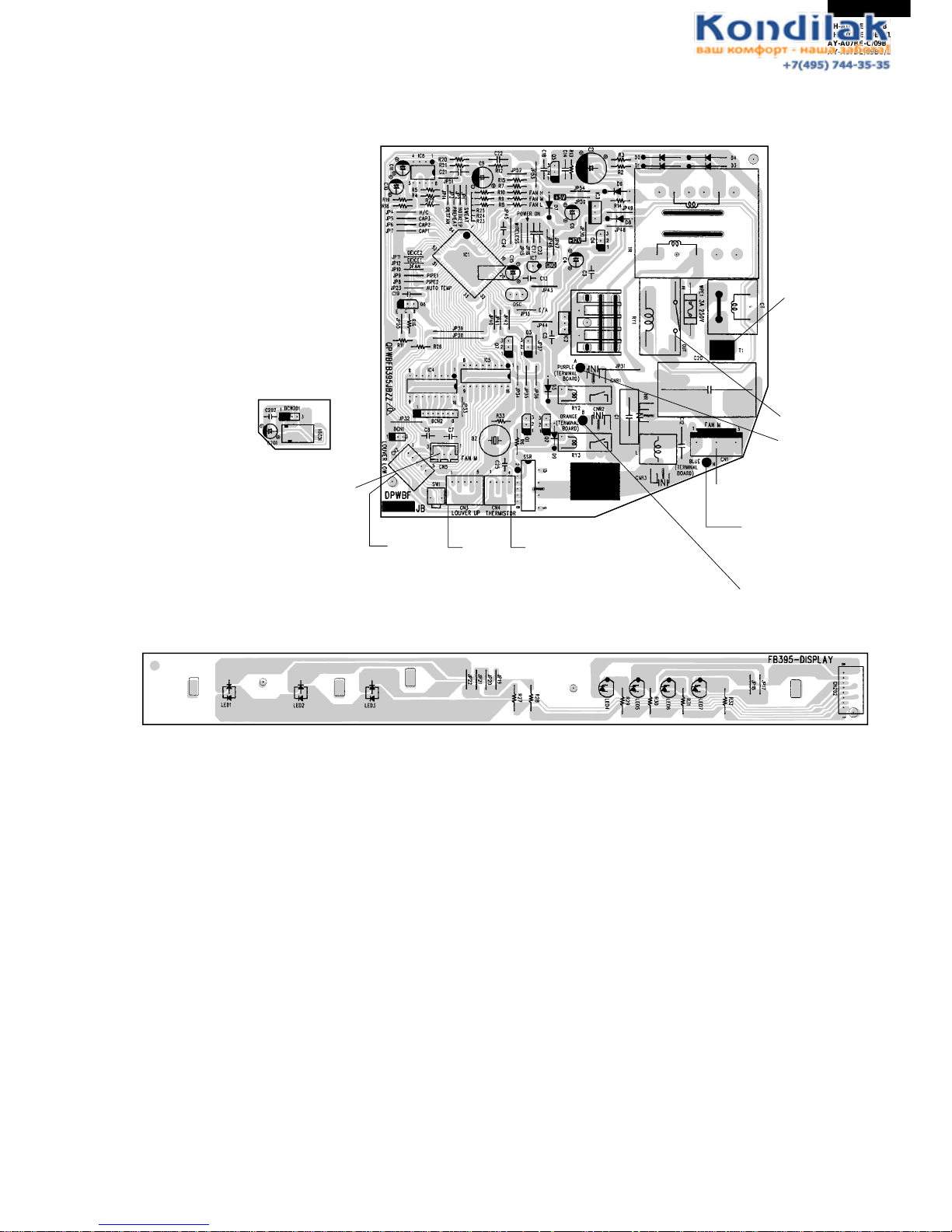
Fig. L-3 Printed Wiring Diagram for AY-A07BE/A07BE-C/A09BE/A09BE-C/A12BE
FROM
TERMINAL
BOARD
(POWER) " 1 "
FROM
TERMINAL
BOARD
(UNIT) " 1 "
FROM
TERMINAL BOARD
(UNIT) " N "
FROM
TERMINAL
BOARD
" 2 "
FROM
TERMINAL BOARD
" 3 "
FROM
THERMISTOR
FROM
LOUVER
(UPPER)
FROM
LOUVER
(LOWER)
INDOOR
FAN MOTOR
(R.P.M. SIGNAL)
INDOOR
FAN MOTOR
Page 16
16
AH-A07BE-C/09BE-C
AH-A07BE/09BE/12BE
AY-A07BE-C/09BE-C
AY-A07BE/09BE/12BE
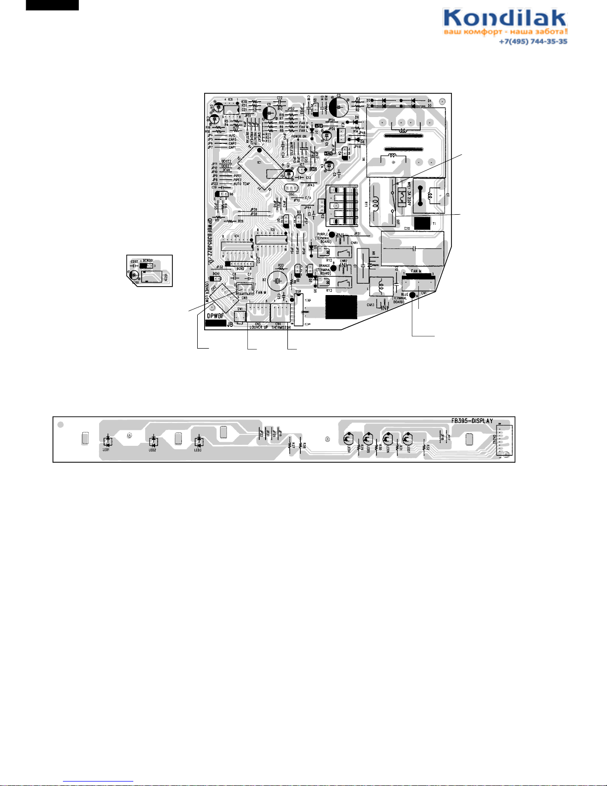
Fig. L-4 Printed Wiring Diagram for AH-A07BE/A07BE-C/A09BE/A09BE-C/A12BE
FROM
TERMINAL
BOARD
(POWER) " 1 "
FROM
TERMINAL
BOARD
(UNIT) " 1 "
FROM
TERMINAL BOARD
(UNIT) " N "
FROM
THERMISTOR
FROM
LOUVER
(UPPER)
FROM
LOUVER
(LOWER)
INDOOR
FAN MOTOR
(R.P.M. SIGNAL)
INDOOR
FAN MOTOR
Page 17

AH-A07BE-C/09BE-C
AH-A07BE/09BE/12BE
AY-A07BE-C/09BE-C
AY-A07BE/09BE/12BE
17
FUNCTIONS
AH-A07BE/A07BE-C/A09BE/A09BE-C/A12BE
are noty provided with the heating function
1. Temperature control characteristic
1-1 COOL operation
In the “COOL” mode, the thermostat circuit is
controlled by four thermostat lines (C1 thru C4).
1-3 HEAT operation
In the “HEAT” mode, the thermostat circuit
is controlled by six thermostat lines (H01 thru
H4).
Figure Y-1
1-2 DRY operation
In the “DRY” mode, the thermostat circuit is
controlled by three thermostat lines (D1 thru
D3).
Figure Y-3
2. Operation modes
2-1 COOL operation
The compressor turns on or off, at the
thermostat lines C3 and C4. The outdoor fan
motor is also controlled with the compressor.
Figure Y-4
Figure Y-2
Room temperature
Preset temperature
Room
temperature
transition
C3
C4
States 1 & 3 : Compressor ON
State 2 : Compressor OFF
1
2
3
18
32
C1
C2
C3
C4
17.5
18.5
19.5
20.5
31.5
32.5
33.5
34.5
Preset temperature (˚C)
Room temperature (˚C)
Room temperature(˚C)
Preset temperature (˚C)
18
32
D1
D2
D3
17.5
18.5
19.5
31.5
32.5
33.5
Preset temperature (˚C)
H4
H3
H2
H1
H02
H01
17
19
21
22
24
26
31.5
32.5
34.0
35.0
36.0
37.0
18 32
Room temperature(˚C)
Page 18

18
AH-A07BE-C/09BE-C
AH-A07BE/09BE/12BE
AY-A07BE-C/09BE-C
AY-A07BE/09BE/12BE
Figure Y-5
2-2 DRY operation
On the switch on, the compressor always starts
to operate for 2 minutes with fan speed “DL” .
The microcomputer reads the room temperature
2 minutes after this first compressor operation.
This room temperature is set as the preset
temperature automatically.
The preset temperature ranges from 18˚C to
32˚C. When the room temperature is below
18˚C, the preset temperature is set to 18˚C,
and when the room temperature is over 32˚C,
the preset temperature is set to 32˚C.
Dry operation is divided into three zones
(Cooling zone, Dehumidifying zone and
Circulating zone) by thermostat lines (D1 to
D3), and the compressor and the fan motor
are controlled in each zone as shown in Table
Y-1.
Room temperature
Preset temperature
Room
temperature
transition
D3
D2
D1
States 1 & 5 : Cooling zone
States 2 & 4 : Dehumidifying zone
States 3 : Circulating zone
3
4
5
1
2
Room temperature
Preset temperature
Room
temperature
transition
States 1 & 3 : Compressor ON
States 2 : Compressor OFF/(ON)
(Hot-keep function)
H1
H2
3
1
2
Compressor
Cooling zone
Dehumidifying zone
Circulating zone
Fan speed
ON "DH"
"DL"
"DL" or OFF
ON
OFF
Table Y-1
2-3 Heat operation
The compressor turns on or off, at State 2 ,
turns on continuously at State 1 & 3 .
Figure Y-6
3. Fan speed
Fan speeds are given by the indoor fan motor, "DL"~"HH" which are available in the following operation mode.
Table Y-2
Fan switch
DL
Fan speed
Fan switch (AUTO)
07BE/07BE-C TYPE
AY AH AY AH AY AH
(r.p.m.)
630 630 690 690 750 750
710 710 740 740 840 840
710 710 760 760 840 840
750 750 790 790 860 860
830 830 910 910 930 930
900 900 990 990 970 970
950 950 1090 1090 1010 1010
700 750 850
830 920 920
850 950 950
900 1000 1000
950 1050 1040
990 1100 1080
09BE/09BE-C TYPE
12BE TYPE
DH
DRY
COOL
CL
COOL SOFT
CAL
CM
COOL LOW
CAH
CH
COOL HIGH
HUL
HL
HEAT SOFT
HEAT
HAL
HM
HEAT LOW
HAH
HH
HEAT HIGH
Page 19

AH-A07BE-C/09BE-C
AH-A07BE/09BE/12BE
AY-A07BE-C/09BE-C
AY-A07BE/09BE/12BE
19
OFF OFF
ON
ON
U1
U2
U1
U2
U2'U2'
Within 3 minutes Over 3 minutes
Figure Y-8
Figure Y-7
5. Preheat air flow
This function is intended to prevent cold air from being
discharged when the heating operation starts or when
defrosting.
When the indoor pipe temperature is below 29˚C at the
begining of the heat operation or after defrosting, the
indoor fan motor stays.
When the indoor pipe temperature gets higher than
29˚C, the fan motor is turned on at speed “HUL” after
compensation of starting.
When the indoor pipe temperature exceeds 35˚C, the
specified fan speed is restored. When the indoor pipe
temperature falls below 30˚C, the fan speed shifts
down to “HUL”. And, when the indoor pipe temperature
falls below 23˚C, the fan motor turns off. Then, over
29˚C , it turns on again at speed “HUL”.
4. Hot-Keep
This function automatically controls the on-off operation
of the indoor fan motor in accordance during the
heating operation, thereby preventing the air conditioner
from delivering a cold air when the compressor is off.
When the room temperature exceeds the thermostat
line “H1”, the compressor is turned off, and the indoor
fan motor is turned off after rotating at “HUL” for 30
seconds. 3 minutes and 10 seconds after turning off the
compressor, the indoor fan motor is turned on for 3
minutes and 20 seconds. At 10 seconds after turning
on the compressor, the indoor fan motor is turned on.
The next compressor OFF time is for 3, 8 or more than
8 minutes according to the room temperature (the time
increases with a rise of room temperature) when 3
minutes elapse after turning on the compessor.
6. Overheating protection system
When overloading occurs during the heating operation,
this system controls the outdoor fan motor according to
the indoor pipe temperature to prevent the overloading
of the compressor and restrain the rise in high pressure.
When the indoor pipe temperature exceeds U1˚C, the
outdoor fan motor is turned off, and when the indoor
pipe temperature falls U2˚C, the outdoor fan motor
turns on.
If 3 minutes elapse after turning off outdoor fan motor,
the outdoor fan motor is turned on, when the indoor
pipe falls U2' ˚C,
Pipe temperature(˚C)
24
29
30
35
OFF
UL UL UL
OFFPreset
Fan speed
Figure Y-9
Table Y-3
Compressor
ON
OFF
Indoor
fan motor
30sec.
time
UL
ON
OFF
3 min.
3 min.
10sec.
UL
30sec.
10sec.
Thermo off
HH
HAH
HM
HAL
HL
HUL
53˚C53˚C
52˚C52˚C
U1
AY-A07BE
AY-A07BE-C
AY-A09BE
AY-A09BE-C
AY-A12BE
U2'
49˚C
53˚C
52˚C
49˚C
53˚C
52˚C
49˚C
49˚CU2
54˚CU2
53˚CU'2
50˚CU2
54˚CU2
53˚CU2'
50˚CU2
Fan speed
LIne
MODELS
Page 20

20
AH-A07BE-C/09BE-C
AH-A07BE/09BE/12BE
AY-A07BE-C/09BE-C
AY-A07BE/09BE/12BE
7. Current control
This system, in order to prevent overcurrent during
heating operation, controls the outdoor fan motor and
changes the indoor fan motor speed by detecting total
current. When the current exceeds P2, the outdoor fan
motor is automatically turned off, and when the current
falls below P4, the outdoor fan motor is turned on.
When the current exceeds P3 and the indoor fan speed
shifts down because of cold air (5. Preheat air flow), the
changes in the indoor fan speed shifts up as follows,
from "off" to "HUL", or from "HUL" to "HL". And when
the current falls bellow P5, the indoor fan speed shift up
is canceled.
Figure Y-10
8. Freeze preventive
When the indoor pipe temperature falls below 0˚C
during cool operation or dry operation, the compressor
is turned off.
9. Defrost
The defrost timer (integrating the operation time of
compressor) counts time with microcomputer during
heat operation.
Frost of outdoor pipe is estimated by indoor pipe
temperature (TH2), room temperature (TH1), indoor
fan speed and operation state of compressor.
In the defrost operation, first the compressor is turned
off, the fan speed is set to “HUL” and the outdoor fan
motor is turned off.
30 seconds later the indoor fan motor is turned off, 60
seconds later the reverse valve is turned off, and the
compressor is turned on. In the end of defrosting, the
compressor is turned off, the outdoor fan motor is
turned on, 60 seconds later the reverse valve is turned
on, and the compressor is turned on, starting heat
operation. At this time, the indoor fan motor is turned
off or the fan speed is set to “HUL” if preheat air flow
function is effective.
Figure Y-11
Figure Y-12
10. Delayed operation of the reverse valve
When the heat operation is shut down or the operating
mode is switched from heat to cool or dry, or vice versa,
the reverse valve is switched after 3 minutes.
11. Test run
If the "AUX" button on the unit is pressed for 5 seconds
or more during operation, cool test operation starts.
The operation LED (red) flickers during test run.
To put the system in the heating test run mode, start the
cooling operation and select the heating mode on the
remote control. In cool and heat mode continuous
compressor on operation is performed. In dry mode the
operation is in dehumidifying zone. In fan only mode
the indoor fan motor runs continusly.
12.Timer
12-1 ON/OFF TIMER
When the unit operates during one hour after
the OFF-time is set, thermostat setting is
automatically shifted (+1˚C in cool operation
and dry operation, -3˚C in heat operation, 16˚C
- 32˚C). When the ON-timer is set in heat
operation and cool operation, operation starts
before 0 to 30 minutes(depends on the room
temperature) so that preset temperature is
obtaind at set time.
12-2 ONE-HOUR TIMER
When ONE-HOUR timer is set, the unit turns
off automatically after one hour. The one hour
timer operation has priority over other time
operation, such as the TIMER ON and TIMER
OFF. If the ONE-HOUR TIMER button is
pressed again during operation, the unit will
operate additionally for another one hour.
Outdoor
Fan motor
OFF
Indoor
Fan motor
Shift UP
Compressor
OFF
Time
Input current
Current transition
P1 5.1A 6.6A 10.0A
P2 4.3A 5.3A 8.0A
P3 3.9A 4.7A 7.2A
P4 3.3A 3.8A 6.1A
P5 3.0A 3.4A 3.5A
AY-A07BE
AY-A07BE-C
AY-A09BE
AY-A09BE-C
AY-A12BE
Switch ON
Heating
Heating
Heating
Min.
40min.
Max.
8min.
(AY--A07BE/A07BE-C)
9min.
(AY--A09BE/A09BE-C/A12BE)
Min.
30min.
Max.
8min. (AY--A07BE/A07BE-C)
9min. (AY--A09BE/A09BE-C/A12BE)
DefrostDefrost
Defrost start
Compressor
Reverse
Valve
Outdoor
Fan Motor
Indoor
Fan Motor
Preheat Air
Flow Control
30sec.
MAX. 9min.
(AY-A09BE/A09BE-C/A12BE)
MAX. 8min.
(AY-A07BE/A07BE)
60sec.
60sec.
ON
OFF
ON
OFF
ON
OFF
ON
OFF
60sec.
HUL
Page 21

AH-A07BE-C/09BE-C
AH-A07BE/09BE/12BE
AY-A07BE-C/09BE-C
AY-A07BE/09BE/12BE
21
ON
OFF
ON
OFF
ON
ON
ON
OFF
ON ON OFF
OFF ON OFF
ON ON ON
OFF
ON/UL/OFF
ON
ON UL/OFF ON
OFF OFF OFF
ON
L/UL
UL/D
OFF D/OFF
OFF
OFF
OFF
Mode
Compressor
Outdoor
Fan Motor
Cooling
Circulating
Normal
Preheat
Air Flow
Control
ON Defrost
Indoor
Fan Motor
Valve
Coil
C
O
O
L
H
E
A
T
D
R
Y
Cooling
Circulating
Dehumidiflying
Room temperature
Preset temperature
Room
temperature
transition
C3
C2
C1
States 1 & 5 :"CAH"
States 2 & 4 : "CM"
States 3 : "CAL"
a. COOL operation
3
4
5
1
2
Room temperature
Preset temperature
Room
temperature
transition
States 1 & 7 : "HAM"
States 2 & 6 : "HM"
States 3 & 5 : "HAL"
States 4 : "HUL", "HL", OFF
H1
H2
1
H4
H3
6
5
4
7
2
3
b. HEAT operation
13. Automatic air conditioning
When automatic air conditioning is selected, the
operation mode and preset temperature are set
automatically according to the room temperature on
starting operation.
Table Y-4
When DRY mode is selected by the micro computer
15. Outputs in each operation mode
Table Y-5
16. Power on start
If the connecting wire "POWER ON" (JP16) is cut on
the PWB ass'y, when the power is supplied by turning
on a circuit breaker, the air conditioner automatically
starts of operation in "AUTO".
(Refer to Figure L-2. Printed Wiring Board.)
17. AUTO RESTART
Power failure occurs during operation, the unit will
retart in the same operation mode as before after
power recovery.
(Refer to Figure L-2. Printed Wiring Board.)
18.Test mode
Keep pushing the "AUX." buttons and supply the
power, the system will go to the test mode. In this
mode, the output of operation is switched by pushing
the ""AUX." button in the unit or the "OI" button in the
remote controller. Normal outputs are shown in Table
Y-6 and Y-7.
with AUTO operation, the fan speed lamps on the
indoor unit panel will indicate identically with the fan
speed symbols on the remote control dispaly, as the
FAN spped setting is changed accordingly. Despite,
the actual fan speed will not change, as it is determined
automatically by the micro computer.
14. Automatic fan speed
When the automatic fan speed is selected in cool or
heat operation, the fan speed is automatically changed
by the thermostat lines C1 to C3 in cool operation, and
H1 to H4 in heat operation.
Figure Y-13
Figure Y-14
Room temperature
at operation start
Operation
Mode
Preset
Temperature
Above 28˚C
Below 21˚C
26˚C
26˚C 28˚C
24˚C 26˚C
21˚C 24˚C
25˚C
24˚C
Room temperature
at operation start
23˚C
COOL
DRY
HEAT
Page 22

22
AH-A07BE-C/09BE-C
AH-A07BE/09BE/12BE
AY-A07BE-C/09BE-C
AY-A07BE/09BE/12BE
19.Diagnosis procedure
When indoor fan motor is out of order or compressor lock occurs, the compressor, indoor fan motor, outdoor fan
motor, and louver are all stopped and the operation LED(red) turns on or off syncronously with the timimg of the
timer LED.
When the thermistor for room temperature or pipe temperature is open or short state, the operation LED turns on
or off syncrnoously with the timing of the timer LED by pushing continously for more than 5 seconds "AUX."
button during suspension of operation.
Timing chart of Timer LED and Operation LED of DIAGNOSIS PROCEDURE.
When "OI" button the remote controller or "AUX." button in the unit is pushed, the unit is free from DIAGNOSIS
PROCEDURE.
Indoor
fan motor
Comp.-lock
Thermistor
short state
Thermistor
open state
Timer
LED
ON
OFF
ON
OFF
ON
OFF
ON
OFF
ON
OFF
Operation
LED
Operation
LED
Operation
LED
Operation
LED
1sec. 1sec.
4sec.
Page 23

AH-A07BE-C/09BE-C
AH-A07BE/09BE/12BE
AY-A07BE-C/09BE-C
AY-A07BE/09BE/12BE
23
Table Y-6 [AY-A07BE/A07BE-C/A09BE/A09BE-C/A12BE]
1110987654321
ON ON
OFF
OFF ON ON OFF ON OFF OFF OFF OFF
OFF ON OFF ON OFF ON ON ON OFF
ON ON OFF ON OFF ON ON ON OFF
ON ON OFF OFF OFF OFF OFF OFF OFF
OFF ON OFF OFF OFF OFF OFF OFF OFF
OFF OFF ON ON OFF ON ON ON OFF
OFF
CLOSE
OFF OFF OFF OFF OFF OFF OFF
ON ON ON ON ON ON ON ON OFF
ON OFF ON OFF ON OFF ON OFF ON
OFF ON ON ON OFF OFF OFF OFF
OFF
ON
OFF
ON
ON
OFF
OFF
OFF
ON
ON
OFF
OFF
OFF
ON
ON
ON
OFF
OFF
OFF
ON
ON
OFF
OFF
OFF
ON
ON
ON
ON
ON
OFF
CLOSE
ON
OFF
ON
OFF
ON
ON
ON
ON
ON
OFF
CLOSE
ON
OFF
ON
OFF
OFF OFF
OFF
ON
ON
OFF
OFF
ON
OFF
ON
OFF
ON
OFF
OFF
ON
ON
OFF
OFF
ON
OFF
ON
OFF
ON
OFF
OFF
ON
OFF
ON
OFF
OFF
ON
OFF
ON
ON
ON
OFF
ON
OFF
ON
OFF
OFF
ON
OFF
ON
ON
ON
OFF
OFF
OFF
ON
ON
OFF
OFF
ON
OFF
ON
OFF
OFF
OFF
OFF
ON
ON
OFF
OFF
ON
OFF
ON
OFF
OFF
OFF
OFF
OFF
ON
ON
OFF
OFF
ON
OFF
ON
ON
OFF
OFF
OFF
OFF
OFF
OFF
OFF
OFF
OFF
ON
ON
OFF
OFF
OFF
OFF
ON
ON
OFF
OFF
ON
OFF
ON
OFF
OFF
OFF
OFF
ON
ON
OFF
OFF
ON
OFF
ON
OFF
OFF
OFF
OFF
OFF
OFF
OFF
OFF
OFF
OFF
OFF
OFF
ON
OFF
OFF
OFF
OFF
OFF
OFF
OFF
OFF
OFF
OFF
ON
OFF
OFF
OFF
OFF
OFF
ON
OFF
ON
ON
FLICK
ON
ON
ON
OPEN
OFF
ON
OFF
OFF
RED
YELLOW
FAN SOFT
FAN LOW
Lamps
Louver
Indoor fan
Outdoor fan
4-way valve
Compressor
FAN HIGH
AUTO
RED
YELLOW
Lamps
Louver
Indoor fan
Outdoor fan
4-way valve
Compressor
AUTO
RED
YELLOW
Lamps
Louver
Indoor fan
Outdoor fan
4-way valve
Compressor
AUTO
Step
AY-A07BE
AY-A07BE-C
AY-A09BE
AY-A09BE-C
AY-A12BE
1
2
ON
ON
ON
ON
OPEN
OFF
ON
OFF
OFF
1
2
ON
ON
ON
ON
OPEN
OFF
ON
OFF
OFF
1
2
3
ON
OFF
OFF
OFF
OFF
ON
OFF
ON
ON
FLICK
3
ON
OFF
OFF
OFF
OFF
ON
OFF
ON
ON
FLICK
3
ON
OFF
OFF
OFF
OFF
ON
OFF
ON
ON
OFF
ON
OFF
OFF
OFF
OFF
ON
OFF
ON
ON
ON
OFF
4
1
2
3
: 7˚C Room temp. 42˚C ON
: 7˚C (Room temp.) or (Room temp.) 42˚C OFF
: –2˚C Pipe temp. 45˚C ON
: –2˚C (Pipe temp.) or (Pipe temp.) 45˚C OFF
: 0.31V (AN2 input voltage) 4.47V ON
: 0.31V (AN2 input voltage) or (AN2 input voltage 4.47V) OFF
4
: When Power on start is effective, 4-way valve is OFF.
ON
4
ON
4
FAN SOFT
FAN LOW
FAN HIGH
FAN SOFT
FAN LOW
FAN HIGH
Page 24

24
AH-A07BE-C/09BE-C
AH-A07BE/09BE/12BE
AY-A07BE-C/09BE-C
AY-A07BE/09BE/12BE
Table Y-7 [AH-A07BE/A07BE-C/A09BE/A09BE-C/A12BE]
1110987654321
ON ON
OFF
OFF
OFF OFF ON ON ON OFF OFF OFF OFF
OFF ON OFF ON OFF ON ON ON OFF
ON ON OFF ON ON ON ON ON OFF
ON ON OFF OFF OFF OFF OFF OFF OFF
OFF ON OFF OFF OFF OFF OFF OFF OFF
OFF OFF ON ON ON ON ON ON OFF
OFF
CLOSE
OFF OFF OFF OFF OFF OFF OFF
ON ON ON ON ON ON ON ON OFF
OFF
ON
OFF
ON
ON
OFF
OFF
OFF
ON
OFF
OFF
ON
ON
ON
OFF
OFF
OFF
ON
OFF
OFF
OFF
ON
ON
ON
ON
OFF
CLOSE
ON
OFF
OFF
ON
ON
ON
ON
OFF
CLOSE
ON
OFF
OFF OFF
ON
ON
ON
OFF
OFF
ON
OFF
ON
OFF
ON
ON
ON
OFF
OFF
ON
OFF
ON
OFF
OFF
ON
OFF
ON
OFF
OFF
ON
OFF
ON
OFF
ON
OFF
ON
OFF
OFF
ON
OFF
ON
OFF
OFF
OFF
ON
ON
OFF
OFF
ON
OFF
ON
OFF
OFF
ON
ON
OFF
OFF
ON
OFF
ON
OFF
OFF
OFF
ON
ON
OFF
OFF
ON
OFF
ON
OFF
OFF
OFF
OFF
OFF
OFF
OFF
OFF
ON
OFF
OFF
OFF
ON
ON
OFF
OFF
ON
OFF
ON
OFF
OFF
ON
ON
OFF
OFF
OFF
ON
ON
OFF
OFF
OFF
OFF
OFF
OFF
OFF
OFF
OFF
OFF
OFF
OFF
OFF
OFF
OFF
OFF
OFF
OFF
OFF
OFF
OFF
OFF
OFF
ON
ON
FLICK
ON
ON
ON
OPEN
OFF
OFF
RED
YELLOW
Lamps
Louver
Indoor fan
Compressor
AUTO
RED
YELLOW
Lamps
Louver
Indoor fan
Compressor
AUTO
RED
YELLOW
Lamps
Louver
Indoor fan
Compressor
AUTO
Step
AH-A07BE
AH-A07BE-C
AH-A09BE
AH-A09BE-C
AH-A12BE
1
2
ON
ON
ON
ON
OPEN
OFF
OFF
1
2
ON
ON
ON
ON
OPEN
OFF
OFF
1
2
ON
OFF
OFF
OFF
OFF
OFF
ON
ON
FLICK
ON
OFF
OFF
OFF
OFF
OFF
ON
ON
FLICK
ON
OFF
OFF
OFF
OFF
ON
OFF
ON
OFF
ON
OFF
OFF
OFF
OFF
ON
OFF
ON
OFF
1
2
: 7˚C Room temp. 42˚C ON
: 7˚C (Room temp.) or (Room temp.) 42˚C OFF
: –2˚C Pipe temp. 45˚C ON
: –2˚C (Pipe temp.) or (Pipe temp.) 45˚C OFF
FAN SOFT
FAN LOW
FAN HIGH
FAN SOFT
FAN LOW
FAN HIGH
FAN SOFT
FAN LOW
FAN HIGH
Page 25

AH-A07BE-C/09BE-C
AH-A07BE/09BE/12BE
AY-A07BE-C/09BE-C
AY-A07BE/09BE/12BE
25
TROUBLESHOOTING GUIDE OF CONTROL CIRCUIT
measure the secondary voltage
of transformer.
YES
NO
YES
NO
The machine does not function
at all with remote controller and
switches on the indoor unit.
Using a tester, measure the
voltage between anodes of D1
and D2 on PWB ass'y.
Is the measured value
approx. 17.0 Vac ?
Replace the PWB with a new
one.
Is the 3.0A fuse down ?
Replace the fuse and varistor
with new ones.
Replace the ftransformer with
a new one.
Page 26

26
AH-A07BE-C/09BE-C
AH-A07BE/09BE/12BE
AY-A07BE-C/09BE-C
AY-A07BE/09BE/12BE
YES
NO
NO
YES
The machine does not function
with remote controller
Push butt "OI" on on the wireless
remote controller.
Is transmitting
indicator of the remote
controller active ?
Is indicator lamp of
indoor unit proper ?
Replace the
PWB with a
new one.
Does beep sound
from the indoor unit ?
Using a tester,
measure the voltage
between terminals
of resistor R11
on the PWB ass'y.
Push the button "OI".
Are batteries of the
wireless remote controller
proper ?
Replace the batteries
with new ones.
Replace the wireless
remote controller.
When the signal is
received, does the voltage
change ?
Replace the PWB with a new
one.
PWB is normal.
Inspect the outdoor unit.
NO
YES
NO
YES
Replace the photo
detector unit with a new
one.
NO
YES
Page 27

AH-A07BE-C/09BE-C
AH-A07BE/09BE/12BE
AY-A07BE-C/09BE-C
AY-A07BE/09BE/12BE
27
The room is not cooled at all
or not cooled.
The compressor does not operate.
Measure resistances of TH1 and TH2.
The control circuit is normal.
The compressor may be defective.
The running capacitor may be defective.
Refrigerant may be leaked.
The outdoor fan motor may be defective.
The outdoor fan motor capacitor may be defective.
Push the button "AUX." on
the indoor unit, for more than 5 sec.
Is the voltage
between terminal "N" and
"1" of the terminal board the
power supply voltage ?
Are the resistances
conformed Fig. 1 ?
Replace the thermistor ass'y with a new one.
NO
YES
YES
NO
Replace the PWB ass'y with a new one.
Fig. 1
Using a tester, measure voltage at
the terminals on the terminal board.
100
80
60
40
20
0
-10 0 10 20 30 40
Resistance
Thermistor
Room temperature
Heat exchange
Color
Yellow
Orange
To measure the resistance, first remove
the connector as shown at right.
Room temperature
thermistor TH1
Tester
Connector
No. 3 to 4
No. 1 to 2
Fig. 1 Temperature properties of indoor thermistors
K
Heat exchange thermistor
TH2 (orange)
25°C resistance 15 K
Room temperature
thermistor TH1 (yellow)
25°C resistance 10 K
Heat exchange
thermistor TH2
Tester
4 1 CN4
Page 28

28
AH-A07BE-C/09BE-C
AH-A07BE/09BE/12BE
AY-A07BE-C/09BE-C
AY-A07BE/09BE/12BE
The room is not heated at all or not heated.
The compressor does not operate.
The control circuit board is normal.
Refrigerant may be leaked.
The running capacitor may be defective.
The outdoor fan motor may be defective.
The outdoor fan motor capacitor may be defective.
The compressor may be defective.
The thermistor may be defective.
Is the voltage
between terminal "N" and
"1" of the terminal board the
power supply voltage ?
NO
Replace the PWB ass'y with a new one.
Push the button of "TEST RUN" on the
indoor unit, and wait 3 minutes.
Using a tester, measure voltages at the
terminals on the terminal board.
Select HEAT MODE with remote controller.
And then start operation.
Is the voltage
between terminal "N" and
"2" of the terminal board the
power supply voltage ?
Is the voltage
between terminal "N" and
"3" of the terminal board the
power supply voltage ?
YES
YES
YES
NO
NO
NO
Page 29

AH-A07BE-C/09BE-C
AH-A07BE/09BE/12BE
AY-A07BE-C/09BE-C
AY-A07BE/09BE/12BE
29
REFRIGERATION CYCLE
Figure R-1. Refrigeration Cycle for AH-A07BE/A07BE-C/A09BE/A09BE-C/A12BE
Figure R-2. Flow of Refrigerant for
AY-A09BE/A09BE-C/A12BE
Figure R-3. Flow of Refrigerant for
AY-A07BE/A07BE-C
1
2
Capillary tube
3
Outdoor unit
Condenser
Evaporator
Indoor unit
Compressor
Flare coupling Flare coupling
Silencer
4
3-way
valve
2-way
valve
Accumulator
s
1
4
C
2
Capillary
tube A
Capillary
tube B
Capillary
tube C
(2 pieces)
Accumulator
3
Strainer
Heating Cooling
Outdoor unit
Condenser
Evaporator
Indoor unit
Reverse valve
Comp-
ressor
Flare coupling Flare coupling
3-way
valve
2-way
valve
Silencer
Coil
s
1
4
C
2
Capillary
tube A
Capillary
tube B
Accumulator
3
Strainer
Heating Cooling
Outdoor unit
Condenser
Evaporator
Indoor unit
Reverse valve
Comp-
ressor
Flare coupling Flare coupling
3-way
valve
2-way
valve
Silencer
Coil
Page 30

30
AH-A07BE-C/09BE-C
AH-A07BE/09BE/12BE
AY-A07BE-C/09BE-C
AY-A07BE/09BE/12BE
Indoor side
Standard conditions:
Dry-bulb Temp. (˚C) Relative Humidity (%)
27Cooling 47
Outdoor side
Dry-bulb Temp. (˚C) Relative Humidity (%)
35 40
AH-A07BE / AH-A07BE-C / AH-A09BE / AH-A09BE-C / AH-A12BE
Temperature at each part and pressure in 3-way valve
Model
1
2
3
4
3-way valve
pressure (MPaG)
76˚C
44˚C
11˚C
8˚C
0.53
76˚C
40˚C
13˚C
7˚C
0.49
81˚C
42˚C
12˚C
10˚C
0.5
Dimension of Capillary tube
AH-A07BE/A07BE-C
AH-A09BE/A09BE-C
AH-A07BE/A07BE-C
AH-A09BE/A09BE-C
AH-A12BE
Model
ø2.7
ø2.7
ø2.7
O.D
ø1.4 ø1.5
ø1.6
400
600
I.D L
O.D
I.D L
O.D
I.D L
500
Capillary tube
AH-A09BE/A09BE-CAH-A07BE/A07BE-C AH-A12BE
Indoor side
Standard conditions:
Dry-bulb Temp. (˚C) Relative Humidity (%)
20Heating
Outdoor side
Dry-bulb Temp. (˚C) Relative Humidity (%)
787
27Cooling 47 35 40
AY-A07BE / AY-A07BE-C / AY-A09BE / AY-A09BE-C / AY-A12BE
Temperature at each part and pressure in 3-way valve
NO.
Condition
Cooling Heating Cooling Heating Cooling Heating
Model
1
2
3
4
3-way valve
pressure (MPaG)
0.54 1.51 0.52 1.54 0.52 1.62
41˚C
70˚C
12˚C
7˚C
74˚C
3˚C
32˚C
3˚C
75˚C
43˚C
13˚C
8˚C
74˚C
2˚C
32˚C
3˚C
41˚C
78˚C
14˚C
11˚C
73˚C
3˚C
32˚C
4˚C
Dimension of Capillary tube
AY-A12BE
Model
ø2.7
ø2.7
O.D
ø1.6
ø1.6
150
I.D L
O.D
I.D L
O.D
I.D L
150
Capillary tube C
ø2.7
ø2.7
ø2.7
ø1.4 ø1.5
ø1.6
700
700
700
Capillary tube B
ø2.7
ø2.7
ø2.7
ø1.4 ø1.5
ø1.6
600
500
400
Capillary tube A
AY-A09BEAY-A07BE AY-A12BE
REFRIGERANT PIPE LENGTH 7.5m
REFRIGERANT PIPE LENGTH 7.5m
Model
O.D
I.D L
O.D
I.D L
Capillary tube C
ø2.7
ø2.7
ø1.4 ø1.5700
700
ø2.7
ø1.6
150
Capillary tube B
ø2.7
ø2.7
ø1.4 ø1.5500
400
Capillary tube A
AY-A09BE-CAY-A07BE-C
Page 31

AH-A07BE-C/09BE-C
AH-A07BE/09BE/12BE
AY-A07BE-C/09BE-C
AY-A07BE/09BE/12BE
31
25 30 35 40
2.4
2.6
2.8
3.0
3.2
12
14
16
600
700
800
900
Cooling capacity(kW)
Outside air temp.(˚C)
Input(W)
Outlet air temp.(˚C)
25 30 35 40
3.2
3.4
3.6
3.8
4.0
10
12
14
900
1000
1100
1200
Cooling capacity(kW)
Outside air temp.(˚C)
Input(W)
Outlet air temp.(˚C)
25 30 35 40
3.2
3.4
3.6
3.8
4.0
10
12
14
900
1000
1100
1200
Cooling capacity(kW)
Outside air temp.(˚C)
Input(W)
Outlet air temp.(˚C)
25 30 35 40
2.0
2.2
2.4
2.6
10
12
14
500
600
700
800
Cooling capacity(kW)
Outside air temp.(˚C)
Input(W)
Outlet air temp.(˚C)
PERFORMANCE CURVES
NOTE: 1) Indoor fan speed: Hi
2) Vertical adjustment louver "45˚", Horizontal adjustment louver "front"
3) Indoor air temp. : Cooling 27˚C, Heating 20˚C
4) Power source : 220V, 50Hz
Figure P-1. At Cooling for AH-A07BE/A07BE-C Figure P-2. At Cooling for AH-A09BE/A09BE-C
Figure P-3. At Cooling for AH-A12BE
Figure P-4. At Cooling for AY-A07BE/A07BE-C
Figure P-5. At Cooling for AY-A09BE/A09BE-C Figure P-6. At Cooling for AY-A12BE
25 30 35 40
2.0
2.2
2.4
2.6
10
12
14
500
600
700
800
Cooling capacity(kW)
Outside air temp.(˚C)
Input(W)
Outlet air temp.(˚C)
25 30 35 40
2.4
2.6
2.8
3.0
3.2
12
14
16
600
700
800
900
Cooling capacity(kW)
Outside air temp.(˚C)
Input(W)
Outlet air temp.(˚C)
Page 32

32
AH-A07BE-C/09BE-C
AH-A07BE/09BE/12BE
AY-A07BE-C/09BE-C
AY-A07BE/09BE/12BE
Figure P-7. At Heating for AY-A07BE/A07BE-C Figure P-8. At Heating for AY-A09BE/A09BE-C
Figure P-9. At Heating for AY-A12BE
-5 0 7510
1.5
2.0
2.5
3.0
35
30
40
400
500
600
700
Heating capacity(kW)
Outside air temp.(˚C)
Input(W)
Outlet air temp.(˚C)
-5 0 5 7 10
2.5
2.0
3.0
3.5
35
40
45
600
700
800
900
Heating capacity(kW)
Outside air temp.(˚C)
Input(W)
Outlet air temp.(˚C)
-5 0 5 7 10
2.5
3.0
3.5
4.0
4.5
5.0
35
40
45
800
900
1000
1100
1200
Heating capacity(kW)
Outside air temp.(˚C)
Input(W)
Outlet air temp.(˚C)
Page 33

AH-A07BE-C/09BE-C
AH-A07BE/09BE/12BE
AY-A07BE-C/09BE-C
AY-A07BE/09BE/12BE
33
DISASSEMBLING PROCEDURE
FOR INDOOR UNIT
CAUTION : DISCONNECT THE UNIT FROM THE POWER SUPPLY BEFORE ANY SERVICING
1. Open the opne panel, and remove 2 air filters.
2. Remove 4 screws fixing the front panel.
3. Remove the screw fixing the cord clamp.
Note: During reassembly, install the holder after
installing the front panel. THis will make it
easier to assemble the front pane.
4. Close the open panel. Pushing the nail of the front
pane.
5. Pull the front panel up.
6. Remove the unit-to-unit wiring from the terminal
board.
7. Remove a screw fixing the control box cover, and
remove it.
8. Remove a screw fixing the ground wire.
Note: During reassembly, take care for the
direction of the lead wire.
Page 34

34
AH-A07BE-C/09BE-C
AH-A07BE/09BE/12BE
AY-A07BE-C/09BE-C
AY-A07BE/09BE/12BE
9. Remove the thermostat of the evaporator.
10. Remove 4 connectors.
11. Remove the thermistor holder from the evaporator.
12. Remove the display from the drain pan.
13. Remove the screw fixing the pipe holder.
14. Remove 3 screws fixing the control box, and remove
the control box.
15. Remove a screw fixing the drain pan.
16. Pull drain pan toward you.
CN1
CN6
CN3
CN2
Page 35

AH-A07BE-C/09BE-C
AH-A07BE/09BE/12BE
AY-A07BE-C/09BE-C
AY-A07BE/09BE/12BE
35
17. Remove the drain cover from the evaporator.
Note: During reassembly, verify that the dew on
the pipe is led to the drain pan.
18. Remove 4 screws fixing the evaporator.
19. Remove the evaporator from the cabinet.
20. Remove 2 screws fixing the motor cover, and pull up
the fan.
21. Loose a screw fixing fan.
[Cautionary points for assembling the fan]
a. When inseting the motor shaft into the metal fan
boss, take care to prevent injuring the inner surface of
the metal fan boss.
b. Before fastening the motor shaft and fan, insert the
motor shaft into contact with the bottom of the metal
fan boss.
Fan motor
Motor shaft
Fan boss
Cross flow fan
Page 36

36
AH-A07BE-C/09BE-C
AH-A07BE/09BE/12BE
AY-A07BE-C/09BE-C
AY-A07BE/09BE/12BE
How to remove the display cover
1
2
1. Push the center of display cover from the back.
2. Slide the display cover to the right.
How to assemble the display cover
1. Slide the left end of the display cover through 3 hooks
on the front panel along the guide from the center of
the front panel.
2. After the left half is inseted completely, press the
display cover and snap in the 3 hooks on the right.
How to remove the control box.
1. Remove the photo detector unit.
(Press and spread the upper hook, and the photo
detector unit will be ready for removal.)
2. Remove the screw fixing the terminal board.
3. Remove a screw fixing the cord holder.
4. Remove 2 screws fixing the board (transformer.
5. Pull the board.
Page 37

AH-A07BE-C/09BE-C
AH-A07BE/09BE/12BE
AY-A07BE-C/09BE-C
AY-A07BE/09BE/12BE
37
Drain pan and related
1. Remove 3 screws fixing motors.
2. Turn the cap area of the drain hose counterclockwise,
and remove it from the drain pan.
During installation, turn the drain hose to the state of
the “engagement position”.
After reinstallation, verify that it is securely fastened.
How to remove the horizontal louver
Slightly pull down the hinge area, defelect thge louver,
and unhook it from the hinge. Remove the shaft from
each of the left and right sides.
Drain pan
Drain Hose
Groove
Projection
To disconned To reconnect
Page 38

38
AH-A07BE-C/09BE-C
AH-A07BE/09BE/12BE
AY-A07BE-C/09BE-C
AY-A07BE/09BE/12BE
FOR OUTDOOR UNIT [AU-A09BE/A09BE-C/A12BE, AE-A09BE/A09BE-C/A12BE]
CAUTION : DISCONNECT THE UNIT FROM THE POWER SUPPLY BEFORE ANY SERVICING
1. Loose a screw fixing the side cover.
2. Loose a screw fixing the cord clamp.
3. Loose the unit-to-unit cord.
4. Loose 4 screws fixing the top panel.
5. Loose 5 screws fixing the front panel.
6. Cut 3 nylon bands.
Right side view Left side view
Front view
7. Remove 5 terminals. [AE-A09BE/A09BE-C/A12BE]
Remove 3 terminals. [AU-A09BE/A09BE-C/A12BE]
AE-A09BEA09BE-C/A12BE AU-A09BEA09BE-C/A12BE
Fan motor 3 3
Reverse valve 2 0
Right side view Left side view
Page 39

AH-A07BE-C/09BE-C
AH-A07BE/09BE/12BE
AY-A07BE-C/09BE-C
AY-A07BE/09BE/12BE
39
8. Remove the terminal cover.
9. Remove 3 terminals.
10. Loose 4 screws fixing the control box.
11. Take out the control box.
DISASSEMBLING PROCEDURE OF THE FAN
1. Loose the fan nut and fan can take out.
2. Fan motor is secured by 4 screws.
Loose
Page 40

40
AH-A07BE-C/09BE-C
AH-A07BE/09BE/12BE
AY-A07BE-C/09BE-C
AY-A07BE/09BE/12BE
1
Left side cover
Condenser
Right side cover
Cabinet
Fan motor Bulkhead
Propeller fan
Compressor
AE-A07BE/A07BE-C
Fan guard
2
3
1
1
3
AU-A07BE/A07BE-C
FOR OUTDOOR UNIT MODEL AE-A07BE/A07BE-C AND AU-A07BE/A07BE-C
CAUTION: DISCONNECT THE UNIT FROM THE POWER SUPPLY BEFORE ANY SERVICING
1 Remove the four (4) screws holding the terminal
cover and right side cover. Then take them out.
2 Remove the three (3) screws holding the left side
cover and take it out.
3 Remove the another screws holding the cabinet
and take it out.
NOTE: Number as shown in following
figure is the moval order.
Fig. D-1. OUTDOOR UNIT
Page 41

AH-A07BE-C/09BE-C
AH-A07BE/09BE/12BE
AY-A07BE-C/09BE-C
AY-A07BE/09BE/12BE
41
REF. NO. PART NO. DESCRIPTION Q'TY CODE
REPLACEMENT PARTS LIST [AH/AY-A07BE/A07BE-C/A09BE/A09BE-C/A12BE]
CABINET AND UNIT PARTS
1- 1 CMOT-A397JBKZ Fan motor sub assembly 1 BG
1- 2 PGUMSA046JBE0 Damper rubber 1 AD
1- 3 CHLD-A067JBK0 Bearing assembly 1 AL
1- 4 DCHS-A399JBKZ Cabinet assembly[except for AY-A12BE, AH-A12BE] 1 BD
1- 4 DCHS-A401JBKZ Cabinet assembly [AY-A12BE, AH-A12BE] 1 BC
1- 5 NFANCA089JBEZ Cross flow fan 1 BD
1- 6 DSRA-A234JBKZ Drain pan sub assembly 1 BB
1- 7 CMOTLA915JBEZ Fan motor 1 BK
1- 8 MJNTPA082JBFA Louver link 2 AC
1- 9 MLOV-A299JBFA Vertical louver 12 AC
1-10 MLOV-A297JBFA Horizontal louver A 1 AK
1-11 MLOV-A298JBFA Horizontal louver B 1 AK
1-12 QW-VZE022JBZZ Fan motor wire 1 AM
1-13 LHLD-A197JBFP Louver holder 2 AX
1-14 NBRG-A026JBFA Louver bushing 2 AB
1-15 LHLD-A476JBFZ Display cover 1 AK
1-16 PHOS-A025JBE0 Drain hose 1 AL
1-17 PPACGA010JBE0 O ring 1 AB
1-18 PGID-A097JBFZ Drain cover 2 AF
1-19 RMOT-A061JBE0 Louver motor 2 AS
1-20 PGUMMA110JBE0 Drain cap 1 AD
1-21 CWAK-C108JBKZ Front panel assembly
[AY-A07BE/A07BE-C/A09BE/A09BE-C/A12BE]
1BK
1-21 CWAK-C109JBKZ Front panel assembly
[AH-A07BE/A07BE-C/A09BE/A09BE-C/A12BE]
1BL
1-22 PPLT-A212JBFZ Side cover R 1 AL
1-23 PPLT-A213JBFZ Side cover L 1 AL
1-24 PCOV-A637JBRA Display cover 1 BC
1-25 PFILMA145JBEA Air filter 2 AL
1-26 DHLD-A010JBKZ Tube holder assembly 1 AK
1-27 HPNL-A520JBFB Open panel 1 AR
1-28 TSPC-D666JBRA Name label [AH-A07BE] 1 AF
1-28 TSPC-E055JBRA Name label [AH-A07BE-C] 1 AF
1-28 TSPC-D662JBRA Name label [AH-A09BE] 1 AE
1-28 TSPC-E056JBRA Name label [AH-A09BE-C] 1 AC
1-28 TSPC-D667JBRA Name label [AH-A12BE] 1 AE
1-28 TSPC-D663JBRA Name label [AY-A07BE] 1 AC
1-28 TSPC-E053JBRA Name label [AY-A07BE-C] 1 AC
1-28 TSPC-D658JBRA Name label [AY-A09BE] 1 AC
1-28 TSPC-E054JBRA Name label [AY-A09BE-C] 1 AD
1-28 TSPC-D664JBRA Name label [AY-A12BE] 1 AC
1-29 PFPFPB901JBEZ Cabinet insulator[except for AY-A12BE, AH-A12BE] 1 AH
1-30 QW-VZE013JBZZ Lead wire (upper) 1 AG
1-31 GWAK-A257JBFA Front panel 1 AX
1-32 PCOV-A614JBFZ Drain cover 1 AG
1-33 TLABCB408JBRZ Wiring diagram [AY-A07BE/A07BE-C/A09BE/A09BE-C/A12BE] 1 AC
1-33 TLABCB413JBRZ Wiring diagram [AH-A07BE/A07BE-C/A09BE/A09BE-C/A12BE] 1 AC
1-34 QW-VZD893JBZZ Lead wire (lower) 2 AG
1-35 LHLD-A303JBFA Tube cover 1 AD
1-36 PSEL-C125JBEZ Panel insulator 1 AF
1-37 HDEC-B108JBEZ Sheet 2 AF
1-38 HDEC-B112JBEZ Sheet 1 AN
1-39 PSEL-C055JBEZ Evaporator seal [AH-A12BE, AH-A12BE] 1 AC
1-40 PSHE-A126JBE0 Evaporator seal 1 AG
1-41 LSPR-A007JBE0 Seet spring 2 AD
1-42 PSEL-C136JBEZ Insulator [AY-A12BE, AH-A12BE] 1 AC
1-43 PFPFPB962JBEZ Insulator 1 AC
1-44 PFPFPB967JBEZ Insulator 1 AC
CONTROL BOX PARTS
2- 1 RTHM-A300JBE0 Thermistor 1 AP
2- 2 PBOX-A342JBFZ Control box 1 AQ
2- 3 PBOX-A341JBFZ Terminal cover 1 AH
2- 4 LHLD-A500JBFZ Thermistor holder 1 AC
2- 5 PCOV-A300JBF0 Thermistor holder cover 1 AB
2- 6 HPNLCA776JBFA Control box cover 1 AG
2- 7 HPNLCA777JBEA Control panel 1 AD
2- 8 PCOV-A618JBFA LED holder 1 AE
2- 9 PCOV-A640JBFA LED holder B 1 AK
2-10 DPWBFA212JBKZ Control board unit [AH-A07BE/A07BE-C] 1 BK
2-10 DPWBFA209JBKZ Control board unit [AH-A09BE/A09BE-C] 1 BK
2-10 DPWBFA213JBKZ Electric control board [AH-A12BE] 1 BK
2-10 DPWBFA210JBKZ Control board unit [AY-A07BE/A07BE-C] 1 BL
2-10 DPWBFA208JBKZ Control board unit [AY-A09BE/A09BE-C] 1 BL
2-10 DPWBFA211JBKZ Control board unit [AY-A12BE] 1 BL
2-11 QACC-A158JBE0 Power supply cord 1 AT
2-12 QTANZA002JBZZ Terminal board(3 pin) 1 AN
2-13 QTANZA002JBZZ Terminal board(3 pin)
[AH-A07BE/A07BE-C/A09BE/A09BE-C/A12BE]
1AN
2-13 QTANZA003JBZZ Terminal board(5 pin)
[AY-A07BE/A07BE-C/A09BE/A09BE-C/A12BE]
1AR
Page 42

42
AH-A07BE-C/09BE-C
AH-A07BE/09BE/12BE
AY-A07BE-C/09BE-C
AY-A07BE/09BE/12BE
REF. NO. PART NO. DESCRIPTION Q'TY CODE
2-14 PCOV-A609JBWZ Control box cover 1 AC
2-15 PCOV-A611JBWZ Control box cover 1 AF
2-16 PCOV-A610JBWZ Terminal cover 1 AE
2-17 VHLGPIU28RR-1 Photo detector unit (IC201) 1 AK
2-18 QFS-GA027JBE0 Fuse 3A 250V 1 AD
2-19 RH-IXA664JBZZ Microcomputer (IC1) 1 AU
2-29 RH-IZA149JBE0
Integrated circuit (IC2)
1AE
2-21 RIC--A022BDE0
Integrated circuit (IC3)
1AE
2-22 RIC--A025BDE0
Integrated circuit(IC4,IC5) [AH-A07BE/A07BE-C/A09BE/A09BE-C/A12BE]
2AE
2-23 VHIBR24C01A-6 E2PROM (IC6) 1 AF
2-24 RH-IZA140JBE0 Integrated circuit (IC7) 1 AE
2-25 RH-VZA020JBE0
Varistor (CNR1,CNR2.CNR3)[AY-A07BE/A07BE-C/A09BE/A09BE-C/A12BE]
3AE
2-25 RH-VZA020JBE0
Varistor (CNR3) [AH-A07BE/A07BE-C/A09BE/A09BE-C/A12BE]
1AE
2-26 RRLYDA010JBZZ Relay (RY1) 1 AH
2-27 RTRN-A291JBZZ Transformer 1 AS
2-28 RH-VXA002JBZZ Varistor (NR) 1 AF
2-29 VHRS201D01/-6 Solid state relay (SSR1) 1 AK
2-30 VHPGL6ZE27+-6 LED <GREEN> (LED4 ~ LED7) 4 AG
2-31 VHPGL6ZR27+-6 LED <RED> (LED2) 1 AF
2-32 VHPGL6ZS27+-6 LED <ORANGE> (LED3) 1 AF
CYCLE PARTS
3- 1 CPIPCA678JBKZ Pipe assembly [except for AH-A12BE, AY-A12BE] 1 BG
3- 1 CPIPCA679JBKZ Pipe assembly [AH-A12BE, AY-A12BE] 1 BH
3- 2 PSEN-A004JBK0 Flare nut assembly(1/4") 1 AE
3- 3 PSEN-A005JBK0 Flare nut assembly(3/8")[except for AH-A12BE, AY-A12BE] 1 AG
3- 3 PSEN-A016JBK0 Flare nut assembly (1/2")[AH-A12BE, AY-A12BE] 1 AR
3- 4 PVLV-0341JBE0 Flare union (1/4") 1 AG
3- 5 PVLV-0342JBE0 Flare union (3/8") [except for AH-A12BE, AY-A12BE] 1 AH
3- 5 PVLV-0406JBE0 Flare union (1/2")[AH-A12BE, AY-A12BE] 1 AK
3- 6 DEVA-A121JBKZ Evaporator assembly[AH-A09BE/A09BE-C, AY-A09BE/A09BE-C] 1 BS
3- 6 DEVA-A122JBKZ Evaporator assembly [AH-A12BE, AY-A12BE] 1 BT
3- 6 DEVA-A123JBKZ Evaporator assembly[AH-A07BE/A07BE-C, AY-A07BE/A07BE-C] 1 BR
ACCESSORY PARTS
4- 1 CRMC-A530JBEZ Remote controller[AY-A07BE/A07BE-C/A09BE/A09BE-C/A12BE] 1 AZ
4- 1 CRMC-A531JBEZ Remote controller[AH-A07BE/A07BE-C/A09BE/A09BE-C/A12BE] 1 AZ
4- 2 UBATUA027JBE0 Battery pack 1 AE
4- 3 LHLD-A477JBFA
Cord holder(for covering the terminal board of indoor unit)
1AE
4- 4 XTTSD40P16000 Tapping screw (for fixing the cord holder) 1 AA
4- 5 LX-NZA207JBEZ Special nut (for fixing long screw steadily) 9 AE
4- 6 LPFT-A029JBF0 Drain hose adpter[AY-A07BE/A07BE-C/A09BE/A09BE-C/A12BE] 1 AD
4- 7 PPLTNA058JBWZ Mounting plate 1 AS
4- 8 XTTSD45P30000 Long screw 8 AA
4- 9 TINSEA266JBRZ Operation manual 1 AM
4-10 TINS-A670JBRZ Installation manual 1 AE
4-11 TINS-A671JBRZ Installation manual 1 AE
4-12 LX-BZA106JBE0 Special screw (for hanging remote controller) 1 AE
SCREWS
5- 1 LX-BZA075JBE0 Special screw (for earth) 1 AA
PACKING PARTS
6- 1 CPADBA038JBKZ Packing pad assembly 1 AK
6- 2 SPAKCA750JBEZ Packing case [AH-A07BE] 1 AR
6- 2 SPAKCA976JBEZ Packing case [AH-A07BE-C] 1 AQ
6- 2 SPAKCA749JBEZ Packing case [AH-A09BE] 1 AR
6- 2 SPAKCA975JBEZ Packing case [AH-A09BE-C] 1 AQ
6- 2 SPAKCA751JBEZ Packing case [AH-A12BE] 1 AR
6- 2 SPAKCA974JBEZ Packing case [AY-A07BE-C] 1 AQ
6- 2 SPAKCA746JBEZ Packing case [AY-A09BE] 1 AR
6- 2 SPAKCA973JBEZ Packing case [AY-A09BE-C] 1 AQ
6- 2 SPAKCA748JBEZ Packing case [AY-A12BE] 1 AR
HOW TO ORDER REPLACEMENT PARTS
To have your order filled prompty and correctly, please furnish the following information.
1. MODEL NUMBER 2. REF. NO.
3. PART NO. 4. DESCRIPTION
Page 43

AH-A07BE-C/09BE-C
AH-A07BE/09BE/12BE
AY-A07BE-C/09BE-C
AY-A07BE/09BE/12BE
43
A
B
C
D
E
F
G
H
A
123456
123456
B
C
D
E
F
G
H
INDOOR UNIT FOR AH/AY-A07BE/A07BE-C/A09BE/A09BE-C/A12BE
1-4
4-1
4-2
4-6
1-35
1-23
1-44
3-6
1-39
1-41
1-40
1-42
1-18
1-5
1-4
1-29
1-3
1-26
4-7
2-11
1-22
1-1
1-12
1-32
1-2
2-1
3-1
2-4
2-5
3-2
3-5
3-3
3-4
2-1
5-1
1-7
2-13
2-2
2-15
2-14
1-21
4-3
4-4
2-6
2-7
1-16
1-30
1-19
1-19
1-13
1-20
1-14
1-13
1-11
1-17
1-10
1-6
1-27
1-24
1-25
1-31
1-37
1-38
1-28
1-36
1-37
1-25
2-3
2-16
2-12
2-10
4-9
4-11
4-8
4-12
4-5
4-10
4-43
2-9
1-15
1-34
1-8
1-8
2-8
1-9
1-9
6-1
6-2
1-33
1-41
INVERTER AIR CONDITIONER
Page 44

44
AH-A07BE-C/09BE-C
AH-A07BE/09BE/12BE
AY-A07BE-C/09BE-C
AY-A07BE/09BE/12BE
REPLACEMENT PARTS LIST [AU-A07BE/A07BE-C]
CABINET AND UNIT PARTS
1- 1 LBSHCA022JBF0 Bushing 1 AE
1- 2 CMOTLA592JBE0 Fan motor 1 BP
1- 3 NFANPA020JBEA Propeller fan 1 AW
1- 4 PANGKA044JBY0 Motor angle ssembly 1 AK
1- 5 PSKR-A094JBP0 Bulkhead [AU-A07BE] 1 AG
1- 5 PSKR-A106JBP0 Bulkhead [AU-A07BE-C] 1 AM
1- 6 GPLTPA014JBFA Left side cover 1 AR
1- 7 CFTA-A266JBKZ Terminal cover ass'y [AU-A07BE] 1 AU
1- 7 CFTA-A276JBKZ Terminal cover ass'y [AU-A07BE-C] 1 AU
1- 8 PBOX-A351JBWZ Control box 1 AK
1- 9 GCAB-A105JBTA Cabinet 1 BA
1-10 GGADFA030JBEA Fan guard 1 AY
1-11 PSEL-C147JBEZ Seal 1 AC
1-12 PSPF-A777JBEZ Compressor cover [AU-A07BE] 1 AT
1-12 PSPF-A695JBE0 Compressor cover [AU-A07BE-C] 1 AZ
1-13 PSEL-A345JBE0 Cabinet seal 1 AK
1-14 TSPC-D665JBRZ Name label [AU-A07BE] 1 AG
1-14 TSPC-E042JBRZ Name label [AU-A07BE-C] 1 AF
1-15 TLABBA029JBRA SHARP badge 1 AD
1-16 CCHS-A751JBTA Base pan assembly [AU-A07BE] 1 BC
1-16 CCHS-A636JBTA Base pan assembly [AU-A07BE-C] 1 BF
1-17 PSPF-A277JBE0 Angle seal 1 AK
1-18 PSEL-A347JBE0 Angle seal 2 AK
1-19 PSEL-A344JBE0 Consensor seal 2 AK
1-20 CPLT-A058JBKZ Side cover ass'y 1 AW
1-21 GPLTMA058JBTA Side cover R 1 AU
1-22 PSEL-C141JBEZ Insulator 1 AU
1-23 PSEL-C142JBEZ Insulator 1 AU
1-24 PSEL-C144JBEZ Insulator 1 AD
1-25 PSEL-C071JBEZ Aluminum tape 1 AC
1-26 TLABCB412JBRZ Wiring diagram [AU-A07BE] 1 AC
1-26 TLABCB573JBRZ Wiring diagram [AU-A07BE-C] 1 AF
1-27 PSEL-C152JBEZ Insulator 1 AE
1-28 PSEL-C145JBEZ Insulator 1 AC
CONTROL BOX PARTS
2- 1 RHOG-A186JBZZ Protector [AU-A07BE] 1 AT
2- 2 LBNDKA062JBW0 Capacitor clamp 1 AD
2- 3 QW-IZA014JBZZ Compressor cord [AU-A07BE] 1 AN
2- 3 QW-IZA028JBZZ Compressor cord [AU-A07BE-C] 1 AP
2- 4 RC-HZA316JBE0 Running capacitor [AU-A07BE] 1 AY
2- 4 RC-HZA301JBE0 Running capacitor [AU-A07BE-C] 1 AX
2- 5 RC-HZA419JBZZ Fan motor capacitor 1 AP
2- 6 QTANZA002JBZZ Terminal board 1 AN
2- 7 LHLD-0261JBM0 Cord holder 1 AB
CYCLE PARTS
3- 1 FCMPRA106JBKZ Compressor ass'y(Including for Ref.No.2-1)[AU-A07BE] 1 CC
3- 1 FCMPRA129JBKZ Compressor ass'y 1 CC
3- 1-1 PCMPRA334JBEZ Compressor [AU-A07BE] 1 CB
3- 1-1 PCMPRA369JBEZ Compressor [AU-A07BE-C] 1 CB
3- 1-2 PSEL-B379JBE0 Terminal gasket [AU-A07BE] 1 AN
3- 1-2 PSEL-B172JBE0 Terminal gasket [AU-A07BE-C] 1 AD
3- 1-3 PSEL-B380JBE0 Gasket washer [AU-A07BE] 1 AG
3- 1-3 PSEL-B722JBE0 Gasket washer [AU-A07BE-C] 1 AE
3- 1-4 PCOV-A628JBEZ Terminal cover [AU-A07BE] 1 AK
3- 1-4 PCOV-A378JBEZ Terminal cover [AU-A07BE-C] 1 AH
3- 1-5 GLEG-A097JBE0 Compressor cushion [AU-A07BE] 3 AF
3- 1-5 GLEG-A085JBE0 Compressor cushion [AU-A07BE-C] 3 AK
3- 1-6 LX-NZA164JBE0 Special nut [AU-A07BE] 1 AE
3- 1-6 LX-NZA152JBE0 Special nut [AU-A07BE-C] 1 AD
3- 2 PCON-A458JBPZ Condenser [AU-A07BE] 1 BS
3- 2 PCON-A477JBPZ Condenser [AU-A07BE-C] 1 BS
3- 3 DVLV-A189JBK0 2 Way valve unit 1 BA
3- 4 PSEN-A004JBK0 Flare nut ass'y 1/4" 1 AE
3- 5 LX-NZA081JBE0 Valve cap 2 AG
3- 6 PGUMSA205JBE0 Damper rubber 1 AC
3- 7 DVLV-A212JBK0 3 way valve unit 1 BB
3- 8 PSEN-A005JBK0 Flare nut assembly 3/8" 1 AG
3- 9 LX-NZA034JBE0 Service cap 1 AD
3-10 PCPY-A777JBPZ Capillary tube 1 AG
3-11 PGUMS0147JBE0 Damper rubber 1 AE
3-12 LX-NZA026JBE0 Special nut 3 AC
3-13 PGUM-0034JBE0 Damper rubber [AU-A07BE-C] 2 AF
REF. NO. PART NO. DESCRIPTION Q'TY CODE
Page 45

AH-A07BE-C/09BE-C
AH-A07BE/09BE/12BE
AY-A07BE-C/09BE-C
AY-A07BE/09BE/12BE
45
HOW TO ORDER REPLACEMENT PARTS
To have your order filled prompty and correctly, please furnish the following information.
1. MODEL NUMBER 2. REF. NO.
3. PART NO. 4. DESCRIPTION
REF. NO. PART NO. DESCRIPTION Q'TY CODE
3-14 LBND-A046JBE0 Wire fixing band [AU-A07BE-C] 2 AE
SCREWS, NUT AND WASHER
4- 1 LX-WZA019JBE0 Special washer 1 AD
4- 2 LX-BZA078JBE0 Special screw 4 AB
4- 3 LX-BZA075JBE0 Special screw 1 AA
4- 4 LX-WZA019JBE0 Special washer 1 AB
4- 5 LX-NZA030JBE0 Special nut 1 AB
4- 6 LX-CZA038WRE0 Special screw 2 AA
4- 7 LX-BZA076JBE0 Special screw 6 AA
4- 8 XCPSD40P20000 Tapping screw 1 AA
PACKING PARTS
5- 1 CPADBA231YDK0 Bottom pad ass'y 1 AP
5- 2 SPAKCA713JBEZ Packing case [AU-A07BE] 1 AX
5- 2 SPAKCA969JBEZ Packing case [AU-A07BE-C] 1 AW
Page 46

46
AH-A07BE-C/09BE-C
AH-A07BE/09BE/12BE
AY-A07BE-C/09BE-C
AY-A07BE/09BE/12BE
A
B
C
D
E
F
G
H
A
123456
123456
B
C
D
E
F
G
H
OUTDOOR UNIT FOR AU-A07BE/A07BE-C
1-6
3-2
1-27
3-1-6
3-1-3
3-1-4
3-1-2
2-1
3-1-1
3-11
2-3
1-16
1-19
AU-A07BE-C
3-13
3-14
3-10
3-13
3-11
3-10
3-6
1-18
1-4
1-18
1-3
4-5
4-6
1-2
4-1
1-9
1-13
1-28
1-15
1-10
1-11
1-5
1-17
3-1-5
3-12
1-1
1-12
3-8
3-4
3-3
4-2
4-2
4-2
4-2
3-5
3-5
3-9
3-7
4-7
2-2
6-7
2-4
2-5
1-8
4-8
2-6
4-3
1-22
1-20
1-21
1-26
1-25
1-24
1-23
1-7
5-1
5-2
Front side
3-1-1
3-14
Page 47

AH-A07BE-C/09BE-C
AH-A07BE/09BE/12BE
AY-A07BE-C/09BE-C
AY-A07BE/09BE/12BE
47
REF. NO. PART NO. DESCRIPTION Q'TY CODE
REPLACEMENT PARTS LIST [AE-A07BE/A07BE-C]
CABINET AND UNIT PARTS
1- 1 PSEL-A345JBE0 Cabinet seal 1 AK
1- 2 CMOTLA592JBE0 Fan motor 1 BP
1- 3 NFANPA020JBEA Propeller fan 1 AW
1- 4 PANGKA018JBP0 Fan motor angle 1 AP
1- 5 PSKR-0106JBP0 Bulkhead 1 AM
1- 6 GPLTPA014JBFA Left side cover 1 AR
1- 7 CFTA-A261JBKZ Terminal cover ass'y [AE-A07BE] 1 AS
1- 7 CFTA-A271JBKZ Terminal cover ass'y [AE-A07BE-C] 1 AU
1- 8 PBOX-A351JBWZ Control box 1 AK
1- 9 GCAB-A105JBTA Cabinet 1 BA
1-10 GGADFA030JBEA Fan guard 1 AY
1-11 PSEL-C147JBE0 Seal 1 AC
1-12 PSPF-A776JBEZ Compressor cover [AE-A07BE] 1 AT
1-12 PSPF-A833JBEZ Compressor cover [AE-A07BE-C] 1 AR
1-13 CPLT-A058JBKZ Side cover ass'y 1 AW
1-14 TSPC-D660JBRZ Name label [AE-A07BE] 1 AD
1-14 TSPC-E040JBRZ Name label [AE-A07BE-C] 1 AD
1-15 TLABBA029JBRA SHARP badge 1 AD
1-16 CCHS-A746JBTA Base pan ass'y [AE-A07BE] 1 BF
1-16 CCHS-A636JBTA Base pan ass'y [AE-A07BE-C] 1 BF
1-17 PSPF-A277JBE0 Angle seal 1 AK
1-18 PSEL-A347JBE0 Angle seal 2 AK
1-19 PSEL-A344JBE0 Condenser seal 1 AK
1-20 LBSHCA022JBF0 Bushing 1 AE
1-21 GPLTMA058JBTA Side cover R 1 AV
1-22 PSEL-C141JBEZ Insulator 1 AU
1-23 PSEL-C142JBEZ Insulator 1 AU
1-24 PSEL-C144JBEZ Insulator 1 AD
1-25 PSEL-C071JBEZ Aluminum tape 1 AC
1-26 TLABCB411JBRZ Wiring diagram [AE-A07BE] 1 AC
1-26 TLABCB572JBRZ Wiring diagram [AE-A07BE-C] 1 AC
1-27 PSEL-C152JBEZ Insulator 1 AE
1-28 PSEL-C145JBEZ Insulator 1 AC
CONTROL BOX PARTS
2- 1 RHOG-A186JBZZ Protector 1 AT
2- 2 LBNDKA062JBW0 Capacitor clamp 1 AD
2- 3 QW-IZA014JBZZ Compressor cord [AE-A07BE] 1 AN
2- 3 QW-IZA028JBZZ Compressor cord [AE-A07BE-C] 1 AP
2- 4 RC-HZA316JBE0 Running capacitor [AE-A07BE] 1 AY
2- 4 RC-HZA301JBE0 Running capacitor [AE-A07BE-C] 1 AX
2- 5 RC-HZA419JBZZ Fan motor capacitor 1 AP
2- 6 QTANZA003JBZZ Terminal board 1 AR
2- 7 LHLD-0261JBM0 Cord holder 1 AB
CYCLE PARTS
3- 1 FCMPRA106JBKZ Compressor ass'y(Including for Ref.No.2-1) [AE-A07BE] 1 CC
3- 1 FCMPRA118JBKZ Compressor ass'y(Including for Ref.No.2-1) [AE-A07BE-C] 1 CC
3- 1-1 PCMPRA334JBEZ Compressor [AE-A07BE] 1 CB
3- 1-1 PCMPRA351JBEZ Compressor [AE-A07BE-C] 1 CB
3- 1-2 PSEL-B379JBE0 Terminal gasket [AE-A07BE] 1 AN
3- 1-2 PSEL-B172JBE0 Terminal gasket [AE-A07BE-C] 1 AD
3- 1-3 PSEL-B380JBE0 Gasket washer [AE-A07BE] 1 AG
3- 1-3 PSEL-B722JBE0 Gasket washer [AE-A07BE-C] 1 AE
3- 1-4 PCOV-A628JBEZ Terminal cover [AE-A07BE] 1 AK
3- 1-4 PCOV-A378JBE0 Terminal cover [AE-A07BE-C] 1 AH
3- 1-5 GLEG-A097JBE0 Compressor cushion [AE-A07BE] 3 AF
3- 1-5 GLEG-A085JBE0 Compressor cushion [AE-A07BE-C] 3 AK
3- 1-6 LX-NZA164JBE0 Special nut [AE-A07BE] 1 AE
3- 1-6 LX-NZA152JBE0 Special nut [AE-A07BE-C] 1 AD
3- 2 PCON-A457JBPZ Condenser [AE-A07BE] 1 BS
3- 2 PCON-A476JBPZ Condenser [AE-A07BE-C] 1 BS
3- 3 DVLV-A189JBK0 2 Way valve ass'y 1 BA
3- 4 PSEN-A004JBK0 Flare nut assembly 1/4" 1 AE
3- 5 LX-NZA033JBE0 Valve cap 2 AF
3- 6 PPIPCB449JBE0 Check valve 1 AM
3- 7 DVLV-A212JBK0 3 way valve unit 1 BB
3- 8 PSEN-A005JBK0 Flare nut assembly 3/8" 1 AG
3- 9 LX-NZA034JBE0 Service cap 1 AD
3-10 CCIL-A098JBEZ Coil 1 AY
3-11 PCPY-A775JBPZ Capillary tube [AE-A07BE] 1 AK
3-11 PCPY-A883JBPZ Capillary tube [AE-A07BE-C] 1 AH
3-12 PCPY-A776JBPZ Capillary tube [AE-A07BE] 1 AK
3-12 PCPY-A884JBPZ Capillary tube [AE-A07BE-C] 1 AK
Page 48

48
AH-A07BE-C/09BE-C
AH-A07BE/09BE/12BE
AY-A07BE-C/09BE-C
AY-A07BE/09BE/12BE
HOW TO ORDER REPLACEMENT PARTS
To have your order filled prompty and correctly, please furnish the following information.
1. MODEL NUMBER 2. REF. NO.
3. PART NO. 4. DESCRIPTION
REF. NO. PART NO. DESCRIPTION Q'TY CODE
3-13 PSRN-A040JBE0 Strainer 1 AN
3-14 PGUMSA234JBE0 Damper rubber 1 AK
3-15 PVLVXA030JBE0 Reverse valve 1 BC
3-16 LX-NZA026JBE0 Special nut 3 AC
3-17 PGUMSA033JBE0 Damper rubber 1 AH
SCREWS, NUT AND WASHER
4- 1 LX-WZA019JBE0 Special washer 1 AB
4- 2 LX-BZA078JBE0 Special screw 4 AB
4- 3 LX-BZA075JBE0 Special screw 1 AA
4- 4 LX-BZA127JBE0 Special screw 1 AC
4- 5 LX-NZA030JBE0 Special nut 1 AB
4- 6 LX-CZA038WRE0 Special screw 2 AA
4- 7 LX-BZA076JBE0 Special screw 6 AA
4- 8 XCPSD40P20000 Tapping screw 1 AA
PACKING PARTS
5- 1 CPADBA231YDK0 Bottom pad ass'y 1 AP
5- 2 SPAKCA709JBEZ Packing case [AE-A07BE] 1 AX
5- 2 SPAKCA968JBEZ Packing case [AE-A07BE-C] 1 AW
Page 49

AH-A07BE-C/09BE-C
AH-A07BE/09BE/12BE
AY-A07BE-C/09BE-C
AY-A07BE/09BE/12BE
49
1-6
3-2
3-1-6
3-1-3
3-1-4
3-1-2
2-1
2-3
1-16
1-16
1-18
1-4
1-18
1-3
4-5
4-1
1-2
1-9
1-1
1-15
1-10
1-11
1-20
1-5
1-17
3-1-5
3-1-1
3-16
1-12
3-15
3-17
3-11, 3-12
3-14
3-10
3-6
6-4
3-8
3-4
3-3
4-2
4-2
4-2
4-2
3-5
3-5
3-9
3-7
2-7
4-7
2-2
4-7
2-4
2-5
1-8
4-8
2-6
4-3
1-22
1-13
1-21
1-26
1-25
1-24
1-23
1-7
5-1
5-2
Front side
1-27
4-6
1-28
4-7
A
B
C
D
E
F
G
H
A
123456
123456
B
C
D
E
F
G
H
OUTDOOR UNIT FOR AE-A07BE/A07BE-C
Page 50

50
AH-A07BE-C/09BE-C
AH-A07BE/09BE/12BE
AY-A07BE-C/09BE-C
AY-A07BE/09BE/12BE
REPLACEMENT PARTS LIST
CABINET AND UNIT PARTS
1- 1 LBSHCA022JBE0 Bushing 1 AE
1- 2 CMOTLA916JBEZ Fan motor [AU-A09BE/A09BE-C, AE-A09BE/A09BE-C] 1 BK
1- 2 CMOTLA917JBEZ Fan motor [AU-A12BE, AE-A12BE] 1 BK
1- 3 NFANPA094JBEZ Propeller fan 1 AK
1- 4 LANGKA124JBPZ Fan motor angle 1 AK
1- 5 LANGKA123JBPZ Fan motor angle sub [AE-A12BE] 1 AE
1- 5 LANGKA127JBPZ Fan motor angle sub [AU-A12BE, AE-A09BE/A09BE-C] 1 AE
1- 5 LANGKA128JBPZ Fan motor angle sub [AU-A09BE/A09BE-C] 1 AG
1- 6 PSKR-A220JBWZ Bulkhead [AU-A12BE] 1 AG
1- 6 PSKR-A215JBWZ Bulkhead [AU-A09BE/A09BE-C, AE-A09BE/A09BE-C/A12BE] 1 AR
1- 7 PFTA-A092JBFA Side cover 1 AQ
1- 8 PCOV-A616JBPZ Protect cover 1 AE
1- 9 GCAB-A195JBTA Front panel 1 BC
1-10 GCAB-A204JBTA Rear cabinet [AU-A09BE/A09BE-C, AE-A09BE/A09BE-C/A12BE] 1 BD
1-10 GCAB-A206JBTA Rear cabinet [AU-A12BE] 1 BD
1-11 GCAB-A197JBTA Top cover 1 AX
1-12 GGADFA037JBFA Fan guard 1 AT
1-13 JHNDPA011JBFA Holder 1 AS
1-14 PSPF-A800JBEZ Compressor cover [AU-A09BE/A09BE-C] 1 AU
1-14 PSPF-A799JBEZ Compressor cover [AU-A12BE] 1 AU
1-14 PSPF-A774JBEZ Compressor cover [AE-A09BE] 1 AW
1-14 PSPF-A831JBEZ Compressor cover [AE-A09BE-C] 1 AR
1-14 PSPF-A775JBEZ Compressor cover [AE-A12BE] 1 AT
1-15 TSPC-D657JBRZ Name Label [AE-A09BE] 1 AD
1-15 TSPC-E041JBRZ Name Label [AE-A09BE-C] 1 AD
1-15 TSPC-D659JBRZ Name Label [AE-A12BE] 1 AD
1-15 TSPC-D661JBRZ Name Label [AU-A09BE] 1 AF
1-15 TSPC-E043JBRZ Name Label [AU-A09BE-C] 1 AD
1-15 TSPC-D668JBRZ Name Label [AU-A12BE] 1 AE
1-16 TLABBA149JBRZ Sharp badge 1 AG
1-17 CCAB-A292JBKZ Front panel ass'y 1 BE
1-18 CCAB-A293JBKZ Rear cabinet ass'y
[AU-A09BE/A09BE-C,AE-A09BE/A09BE-C/A12BE]
1BE
1-18 CCAB-A295JBKZ Rear cabinet ass’y [AU-A12BE] 1 BE
1-19 DCAB-A099JBKZ Top cover ass’y [AU-A09BE] 1 AU
1-19 DCAB-A123JBKZ Top cover ass’y [AU-A09BE-C] 1 AY
1-19 DCAB-A100JBKZ Top cover ass’y [AU-A12BE] 1 AX
1-19 DCAB-A097JBKZ Top cover ass’y [AE-A09BE] 1 AX
1-19 DCAB-A117JBKZ Top cover ass’y [AE-A09BE-C] 1 AY
1-19 DCAB-A098JBKZ Top cover ass’y [AE-A12BE] 1 AX
1-20 FFTA-A014JBKZ Side cover ass’y 1 AT
1-21 CCHS-A747JBTA Base pan ass’y [AU-A09BE, AE-A09BE] 1 BC
1-21 CCHS-A748JBTA Base pan ass’y
[AU-A09BE-C,AE-A09BE-C,AU-A12BE,AE-A12BE]
1BD
1-23 PFPFPB911JBEZ Motor angle cushion 1 AC
1-24 PSEL-C045JBEZ Motor angle cushion 1 AB
1-25 PSEL-C051JBEZ Side cover seal 1 AE
1-26 PSEL-C120JBEZ Side cover seal 1 AC
1-27 PSEL-C121JBEZ Side cover seal 1 AC
1-28 PSEL-C133JBEZ Box insulator 1 AC
1-29 PSEL-C119JBEZ Box insulator 1 AE
1-30 PSEL-C128JBEZ Insulator 1 AD
1-31 PSEL-C048JBEZ F.panel insulator 1 AC
1-32 PSEL-C049JBEZ F.panel insulator 1 AC
1-33 PSEL-C050JBEZ Bulkhead insulator 1 AG
1-34 PSEL-C072JBEZ Insulator [AU-A09BE/A09BE-C, AE-A09BE/A09BE-C/A12BE] 1 AE
1-34 PSEL-C073JBEZ Insulator [AU-A12BE] 1 AF
1-35 PSEL-C132JBEZ F.panel insulator 1 AA
CONTROL BOX PARTS
2- 1 QW-IZA013JBZZ Compressor cord [AU-A09BE, AE-A09BE] 1 AP
2- 1 QW-IZA029JBZZ Compressor cord [AU-A09BE-C, AE-A09BE-C] 1 AQ
2- 1 QW-IZA015JBZZ Compressor cord [AU-A12BE, AE-A12BE] 1 AL
2- 2 RC-HZA389JBE0 Running capacitor [AU-A09BE/A12BE, AE-A09BE/A12BE] 1 BC
2- 2 RC-HZA301JBE0 Running capacitor [AU-A09BE-C, AE-A09BE-C] 1 AX
2- 3 RC-HZA419JBZZ Fan motor capacitor [AU-A09BE/A09BE-C,AE-A09BE/A09BE-C] 1 AP
2- 3 RC-HZA308JBZZ Fan motor capacitor [AU-A12BE, AE-A12BE] 1 AM
2- 4 QTANZA002JBZZ Terminal board [AU-A09BE/A09BE-C/A12BE] 1 AN
2- 4 QTANZA003JBZZ Terminal board [AE-A09BE/A09BE-C/A12BE] 1 AR
2- 5 LHLD-0261JBM0 Cord holder 1 AB
2- 6 TLABCB407JBRZ Wiring diagram [AE-A09BE] 1 AC
2- 6 TLABCB574JBRZ Wiring diagram [AE-A09BE-C] 1 AD
2- 6 TLABCB409JBRZ Wiring diagram [AE-A12BE] 1 AC
2- 6 TLABCB410JBRZ Wiring diagram [AU-A09BE] 1 AC
2- 6 TLABCB575JBRZ Wiring diagram [AU-A09BE-C] 1 AG
2- 6 TLABCB414JBRZ Wiring diagram [AU-A12BE] 1 AC
REF. NO. PART NO. DESCRIPTION Q'TY CODE
[AU-A09BE/A09BE-C/A12BE, AE-A09BE/A09BE-C/A12BE]
Page 51

AH-A07BE-C/09BE-C
AH-A07BE/09BE/12BE
AY-A07BE-C/09BE-C
AY-A07BE/09BE/12BE
51
REF. NO. PART NO. DESCRIPTION Q'TY CODE
HOW TO ORDER REPLACEMENT PARTS
To have your order filled prompty and correctly, please furnish the following information.
1. MODEL NUMBER 2. REF. NO.
3. PART NO. 4. DESCRIPTION
2- 7 LBNDKA062JBW0 Capacitor clamp 1 AD
2- 8 PBOX-A350JBWZ Control box 1 AM
2- 9 CCIL-A098JBEZ Coil [AE-A09BE/A12BE] 1 AY
2-10 RHOG-A185JBEZ Overload relay [AU-A09BE, AE-A09BE] 1 AT
CYCLE PARTS
3- 1 FCMPRA104JBKZ Compressor ass'y [AU-A09BE, AE-A09BE] 1 CD
3- 1 FCMPRA128JBKZ Compressor ass'y [AU-A09BE-C] 1 CC
3- 1 FCMPRA116JBKZ Compressor ass'y [AE-A09BE-C] 1 AY
3- 1 FCMPRA105JBKZ Compressor ass'y [AU-A12BE, AE-A12BE] 1 CE
3- 1-1 PCMPRA333JBEZ Compressor [AU-A09BE, AE-A09BE] 1 CC
3- 1-1 PCMPRA363JBEZ Compressor [AU-A09BE-C] 1 CC
3- 1-1 PCMPRA226JBE0 Compressor [AE-A09BE-C] 1 CF
3- 1-1 PCMPRA231JBE0 Compressor [AU-A12BE, AE-A12BE] 1 CG
3- 1-2 PCOV-A378JBEO Terminal cover [AU-A09BE-C/A12BE, AE-A09BE-C/A12BE] 1 AH
3- 1-2 PCOV-A628JBEZ Terminal cover [AU-A09BE, AE-A09BE] 1 AK
3- 1-3 PSEL-B379JBE0 Terminal gasket [AU-A09BE, AE-A09BE] 1 AN
3- 1-3 PSEL-B172JBE0 Terminal gasket [AU-A09BE-C/A12BE, AE-A09BE-C/A12BE] 1 AD
3- 1-4 PSEL-B380JBE0 Gasket washer [AU-A09BE, AE-A09BE] 1 AG
3- 1-4 PSEL-B722JBE0 Gasket washer [AU-A09BE-C/A12BE, AE-A09BE-C/A12BE] 1 AE
3- 1-5 GLEG-A097JBE0 Compressor cushion [AU-A09BE, AE-A09BE] 3 AF
3- 1-5 GLEG-A085JBE0 Compressor cushion [AU-A09BE-C/A12BE, AE-A09BE-C/A12BE] 3 AK
3- 1-6 LX-NZA164JBE0 Special nut [AU-A09BE, AE-A09BE] 1 AE
3- 1-6 LX-NZA152JBE0 Special nut [AU-A09BE-C/A12BE, AE-A09BE-C/A12BE] 1 AD
3- 2 PCON-A445JBPZ Condenser [AE-A12BE] 1 BS
3- 2 PCON-A455JBPZ Condenser [AE-A09BE/A09BE-C] 1 BT
3- 2 PCON-A459JBPZ Condenser [AU-A12BE] 1 BU
3- 2 PCON-A451JBPZ Condenser [AU-A09BE/A09BE-C] 1 BS
3- 3 DVLV-A461JBKZ 3way valve unit [AU-A09BE/A09BE-C, AE-A09BE/A09BE-C] 1 AY
3- 3 DVLV-A466JBKZ 3way valve unit [AU-A12BE, AE-A12BE] 1 BA
3- 4 DVLV-A462JBKZ 2way valve tube assy 1 AW
3- 5 PSEN-A004JBK0 Flare nut ass’y 1 AE
3- 6 PSEN-A005JBK0 Flare nut ass’y [AU-A09BE/A09BE-C, AE-A09BE/A09BE-C] 1 AG
3- 6 PSEN-A016JBE0 Flare nut ass’y [AU-A12BE, AE-A12BE] 1 AR
3- 7 PGUMSA297JBE0 Damper rubber [AU-A09BE/A09BE-C/A12BE] 1 AC
3- 8 PVLVXA030JBE0 Reverse valve [AE-A09BE/A09BE-C] 1 BC
3- 8 PVLVXA039JBE0 Reverse valve [AE-A12BE] 1 BD
3- 9 CVLV-A576JBKZ Reverse valve ass’y [AE-A09BE] 1 BW
3- 9 CVLV-A622JBKZ Reverse valve ass’y [AE-A09BE-C] 1 BN
3- 9 CVLV-A577JBKZ Reverse valve ass’y [AE-A12BE] 1 BW
3-10 DCPY-A228JBKZ Capillary tube ass’y [AE-A09BE] 1 BF
3-10 DCPY-A260JBKZ Capillary tube ass’y [AE-A09BE-C] 1 AR
3-10 DCPY-A229JBKZ Capillary tube ass’y [AE-A12BE] 1 BF
3-10 DCPY-A230JBKZ Capillary tube ass’y [AU-A09BE/A09BE-C] 1 BF
3-10 DCPY-A231JBKZ Capillary tube ass’y [AU-A12BE] 1 BF
3-11 LX-NZA026JBE0 Special nut 3 AC
3-12 LX-BZA072JBE0 Special screw 4 AB
SCREWS AND NUTS
4- 1 XCPSD40P20000 Tapping screw 1 AA
4- 2 LX-BZA076JBE0 Special screw 8 AA
4- 3 LX-BZA166JBE0 Special screw 1 AB
4- 4 LX-NZA135JBE0 Special nut 1 AC
4- 5 LX-NZA091JBE0 Special screw 31 AA
4- 6 XTTSD40P14000 Tapping screw 1 AA
4- 7 XCTSD40P12000 Tapping screw 2 AA
4- 8 LX-BZA075JBE0 Special screw 1 AA
PACKING PARTS
5- 1 CPADBA031JBKZ Bottom pad assembly 1 AS
5- 2 SPAKCA706JBEZ Packing case [AE-A09BE] 1 AX
5- 2 SPAKCA965JBEZ Packing case [AE-A09BE-C] 1 AY
5- 2 SPAKCA708JBEZ Packing case [AE-A12BE] 1 AX
5- 2 SPAKCA716JBEZ Packing case [AU-A09BE] 1 AX
5- 2 SPAKCA966JBEZ Packing case [AU-A09BE-C] 1 AX
5- 2 SPAKCA717JBEZ Packing case [AU-A12BE] 1 AX
Page 52

52
AH-A07BE-C/09BE-C
AH-A07BE/09BE/12BE
AY-A07BE-C/09BE-C
AY-A07BE/09BE/12BE
AU-A09BE/A12BE
3-1-5
3-1
3-11
1-6
1-1
2-7
2-2
2-4
2-8
1-30
4-8
4-5
2-3
4-7
4-1
1-3
1-2
1-4
1-5
4-5
1-13
5-2
5-1
1-18
1-10
2-5
4-2
4-5
4-5
1-15
1-8
1-27
1-20
4-3
1-7
3-2
1-25
1-26
1-23
1-24
4-4
1-34
1-31
1-32
1-35
1-33
2-1
3-1-3
3-1-2
3-1-4
2-10
2-10
3-1-6
3-1-3
3-1-2
3-1-6
3-1-4
1-21
1-16
1-9
1-17
4-2
4-2
1-12
3-6
3-5
3-10
3-9
3-10
2-9
3-4
3-12
3-3
1-28
1-11
2-6
1-19
4-2
1-29
4-5
4-5
4-2
4-5
4-5
4-5
4-6
4-5
1-14
3-1
Front side
A
B
C
D
E
F
G
H
A
123456
123456
B
C
D
E
F
G
H
OUTDOOR UNIT FOR AU-A09BE/A09BE-C/A12BE, AE-A09BE/A09BE-C/A12BE
'02 SHARP CORP. (4U1.00E) Printed in Netherlands
 Loading...