

Page 1
AR-SS2
CODE : 00ZARSS2//A1E
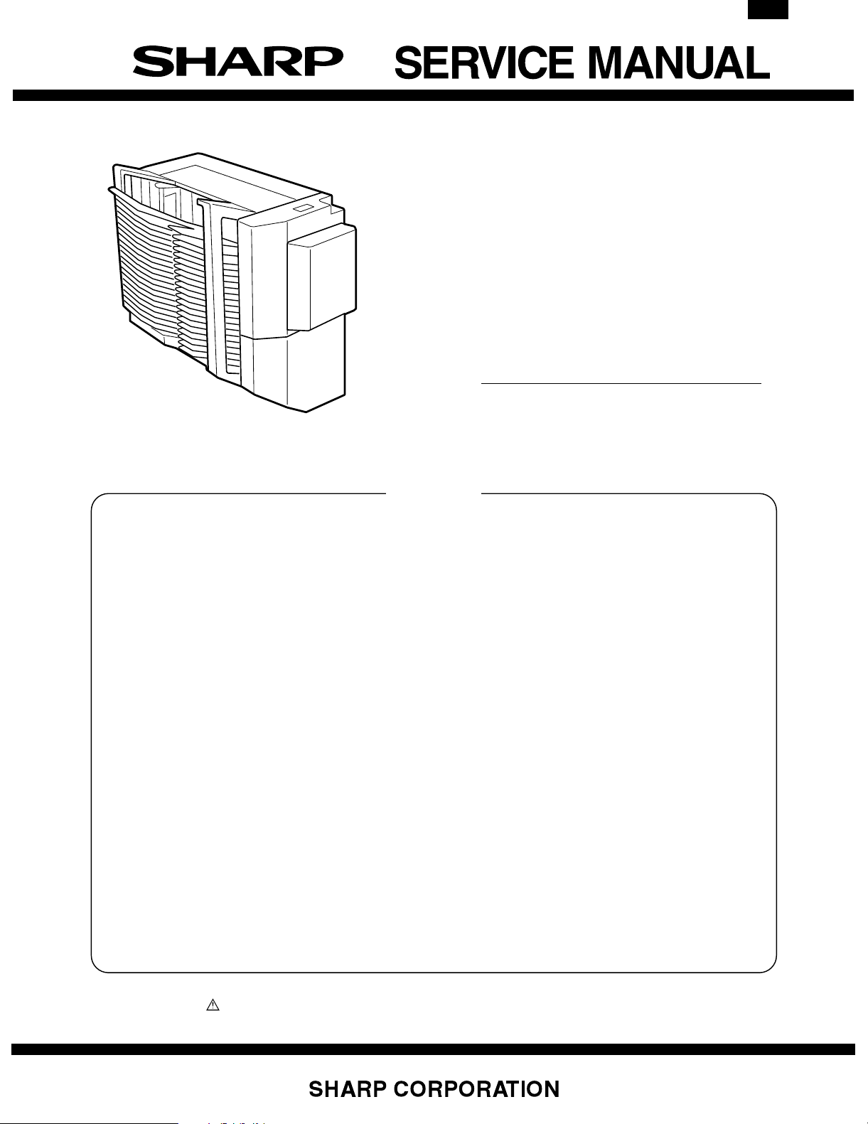
20-BIN STAPLE
SORTER
MODEL AR-SS2
CONTENTS
[ 1 ] SPECIFICATIONS . . . . . . . . . . . . . . . . . . . . . . . . . . . . . . . . . . . 1-1
[ 2 ] UNPACKING AND INSTALLATION . . . . . . . . . . . . . . . . . . . . . 2-1
[ 3 ] EXTERNAL VIEW AND INTERNAL STRUCTURE . . . . . . . . . . 3-1
[ 4 ] DISASSEMBLY AND ASSEMBLY . . . . . . . . . . . . . . . . . . . . . . 4-1
[ 5 ] ADJUSTMENTS . . . . . . . . . . . . . . . . . . . . . . . . . . . . . . . . . . . . 5-1
[ 6 ] DIAGNOSTICS . . . . . . . . . . . . . . . . . . . . . . . . . . . . . . . . . . . . . 6-1
[ 7 ] TROUBLESHOOTING . . . . . . . . . . . . . . . . . . . . . . . . . . . . . . . . 7-1
[ 8 ] MAINTENANCE . . . . . . . . . . . . . . . . . . . . . . . . . . . . . . . . . . . . . 8-1
[ 9 ] OPERATIONAL DESCRIPTIONS . . . . . . . . . . . . . . . . . . . . . . . 9-1
[10] ACTUAL WIRING DIAGRAM . . . . . . . . . . . . . . . . . . . . . . . . . 10-1
■ PARTS GUID E
Parts marked with “ ” are important for maintaining the safety of the set. Be sure to replace these parts with specified ones for
maintaining the safety and performance of the set.
This document has been published to be used
for after sales service only.
The contents are subject to change without notice.
Page 2
AR-SS2
[1] SPECIFICATIONS
Type
20-bin staple sorter (copier-mounted, hook type)
No. of bins
20 bins (incl. non-sort bin)
Loading method
Face up
Bin-shift, open-port system
Kinds of copy paper
With normal paper (64 to 105g/m2) or thick paper (106 to 200g/m2),
max. 2 sheets of covers, back covers, or insert papers can be sorted.
Special paper, 2nd original paper, OHP, postcards, labels
Capacity of each bin: 105g/m2 or equivalent
Non-sort mode
(1-bin only):
Sort mode: 50 sheets (A4, A4R, B5, B5R, A5, 8.5"x11",
Staple sort mode: 30 sheets (A4, A4R, B5, 8.5"x11", 8.5"x11"R)
Group mode: 30 sheets (A4, B5, A5, 8.5"x11", 5.5"x8.5", A4R,
Bin returning time (from 20 bin to 1 bin)
About 10 sec
Limitless function
Not provided
Bin specifying function
Not provided
Operation panel
Staple key
100 sheets (A4, A4R, B5, B5R, A5, 8.5"x11",
8.5"x11"R, 5.5"x8.5", 7.25"x10.25"R)
60 sheets (A3, B4, 11"x17", 8.5"x14", 8.5"x13",
12"x18")
8.5"x11"R, 5.5"x8.5")
25 sheets (A3, B4, 11"x17", 8.5"x14", 8.5"x13")
25 sheets (A3, B4, 11"x17", 8.5"x14", 8.5"x13")
B5R, 8.5"x11"R)
25 sheets (A3, B4, 11"x17", 8.5"x14", 8.5"x13")
Manual stapling: 30 sheets: A4, A4R, B5, 8.5"x11", 8.5"x11"R
Manual feed stapling:
(28 sheets of 105g/m2 + 2sheets of 200g/m2 or
max. thickness 5.5mm)
25 sheets: A3, B4, 11"x17", 8.5"x14", 8.5"x13"
(28 sheets of 105g/m2 + 2sheets of 200g/m2 or
max. thickness 5.5mm)
30 sheets: All sizes
Applicable staple
Staple: SF-SC11 (Cartridge: 5,000 staples)
Staple empty detection
Available (The staple empty display is lighted when the remaining
quantity of staples is 40 pcs or less after stapling.)
Auto staple positioning
Available (Auto staple positioning is started when the stapler unit
cover is closed after staples are supplied.)
Use environment
Temperature: Conforms to the conditions for the copier.
Humidity: Conforms to the conditions for the copier.
Power source
24V (Supplied from the copier)
Max. power consumption
About 60W
Weight
About 26.4kg
Dimensions (Width x Depth x Height)
417 x 594 x 624 mm
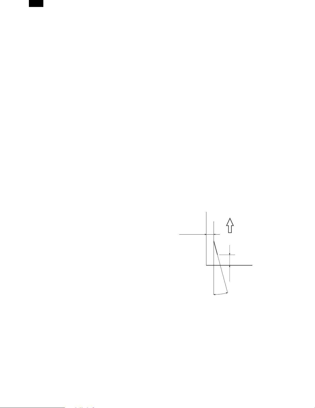
Staple position
6±2.5mm
Transport direction
Display section
Manual staple: Enable/disable (Enable when LED is ON)
Staple supply indication
Stapling system
Punching by the rotation cam
Auto stapling enable copy paper size
A3, A4, B4, B5, A4R, 11"x17", 8.5"x14", 8.5"x11", 8.5"x11"R, 8.5"x13"
Manual stapling enable copy paper size (Stapling by key
operation immediately after copying)
A3, A4, B4, B5, A4R, 11"x17", 8.5"x14", 8.5"x11", 8.5"x11"R, 8.5"x13"
Manual feed stapling enable copy paper size (Stapling by
paper insertion by the user)
All sizes
Number of sheets to be staped (64 to 105g/m2 or
equivalent)
Auto stapling: 30 sheets: A4, A4R, B5, 8.5"x11", 8.5"x11"R
(28 sheets of 105g/m2 + 2 sheets of 200g/m2 or
max. thickness 5.5mm)
25 sheets: A3, B4, 11"x17", 8.5"x14", 8.5"x13"
(28 sheets of 105g/m2 + 2 sheets of 200g/m2 or
max. thickness 5.5mm)
6±2.5mm
15˚
1 – 1
Page 3
[2] UNPACKING AND INSTALLATION
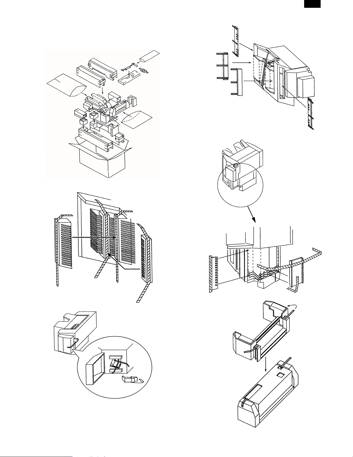
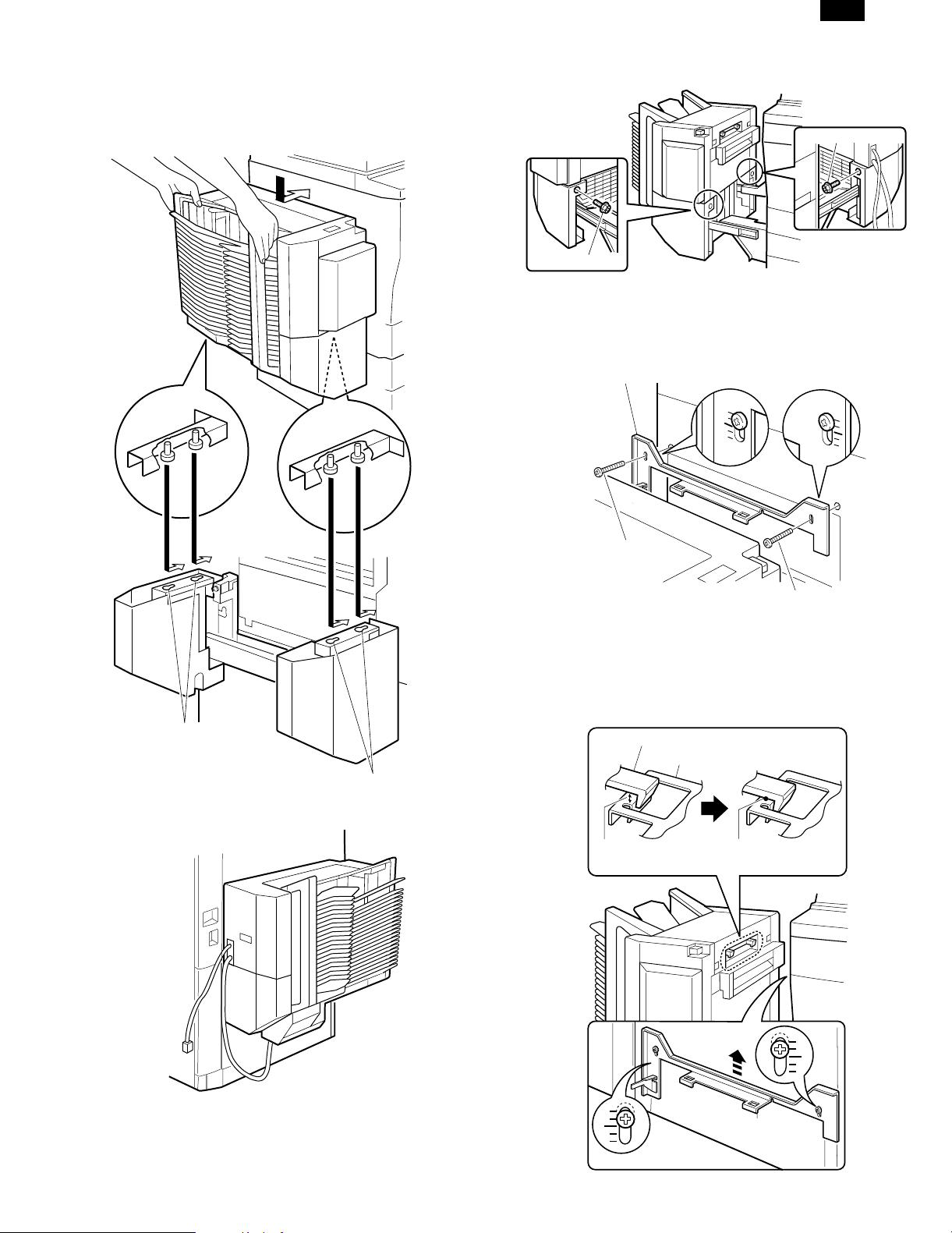
1. Unpacking
AR-SS2
Remove the filament tape and remove the packing of each section.
2 – 1
Page 4
AR-SS2
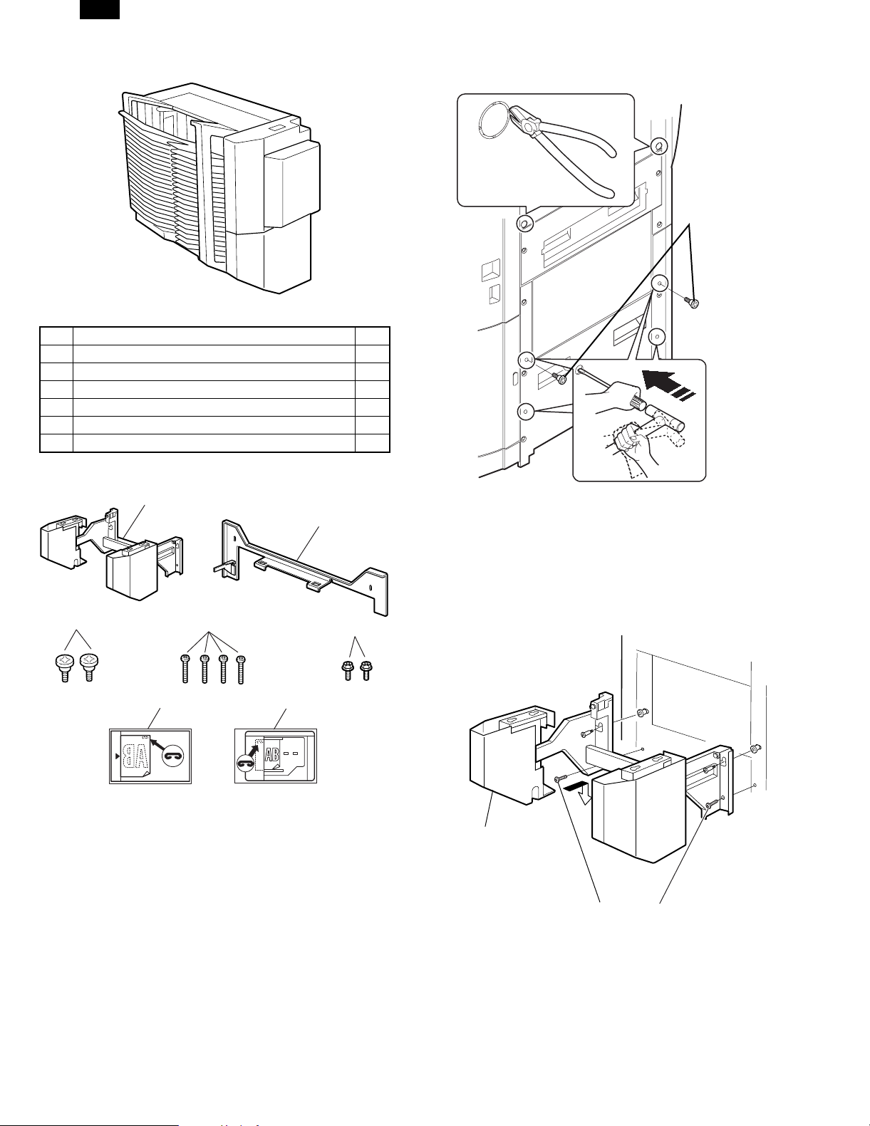
2. Installation
Packed items
1 Rail unit 1
2 Lock plate 1
3 Rail unit fixing screw 2
4 Mounting kit fixing screw (M4 x 18) 4
5 Sorter fixing screw (M4 x 10) 2
6 Stapler position label A (for the copier) 1
7 Stapler position label D (for the RADF) 1
2. Fix the rail unit fixing screw temporarily as shown in
the figure.
Cut-out
Rail unit fixing screws
1
2
3
6
4
7
5
Pull out the power plug of the copier from the
power outlet, and follow the procedures below.
Setting of the copier and the stapler sorter
1. Remove the notch sections of the copier, and install
the rail mounting plate fixing screw.
Use nippers to cut out the two cut-out sections on the upper side of
the left cabinet of the copier. Use a screwdriver to punch out the four
cut-out sections on the lower side. (There are 6 cut-out section in
total.)
Cut-out
3. Install the rail unit
Hang the rail unit on the upper rail unit fixing screws which were fixed
temporarily in procedure 2.
Tighten the mounting kit fixing screw in the position shown in the
figure.
Tighten the upper rail un it f ix in g sc r ew s whic h w ere temporarily fixe d.
Rail unit
Mounting kit fixing screws
2 – 2
Page 5
AR-SS2
4. Fix the sorter to the rail unit.
[Note] When lifting the sorter, hold the sorter as shown in the figure
so as not to make contact with the sorter bin.
Insert the positioning screws on the lower side of the sorter into the
rail unit positioning holes, and slide the sorter inward.
Fix the sorter unit with the sorter fixing screws on the front and the
rear sides of the rail unit.
Sorter fixing screw
Sorter fixing screw
5. Install the lock plate and check that the staple sorter
is installed.
1) Fix the lock plate with two mounting kit fixing screws (M4 x 18 S
tight) with the sorter mounting plate lowered as shown in the
figure.
Lock plate
Positioning holes
Positioning holes
At that time, position the wiring of the sorter as shown in the figure.
Mounting kit fixing screw
Mounting kit fixing screw
2) Lock the staple sorter to the copier body, and check the clearance
between the sorter lock pawl and the lock plate. (Refer to Fig. 1)
3) Loosen two mounting kit fixing screws so that the sorter lock pawl
and the lock plate are in contact horizontally. Adjust the lock plate
height. One scale corresponds to about 2mm. (Refer to Fig. 2)
At that time, check that the paper exit cabinet of the copier can be
opened and closed.
Sorter lock pawl
Lock plate
Clearance
[Fig. 1]
Contact
[Fig. 2]
2 – 3
Page 6
AR-SS2
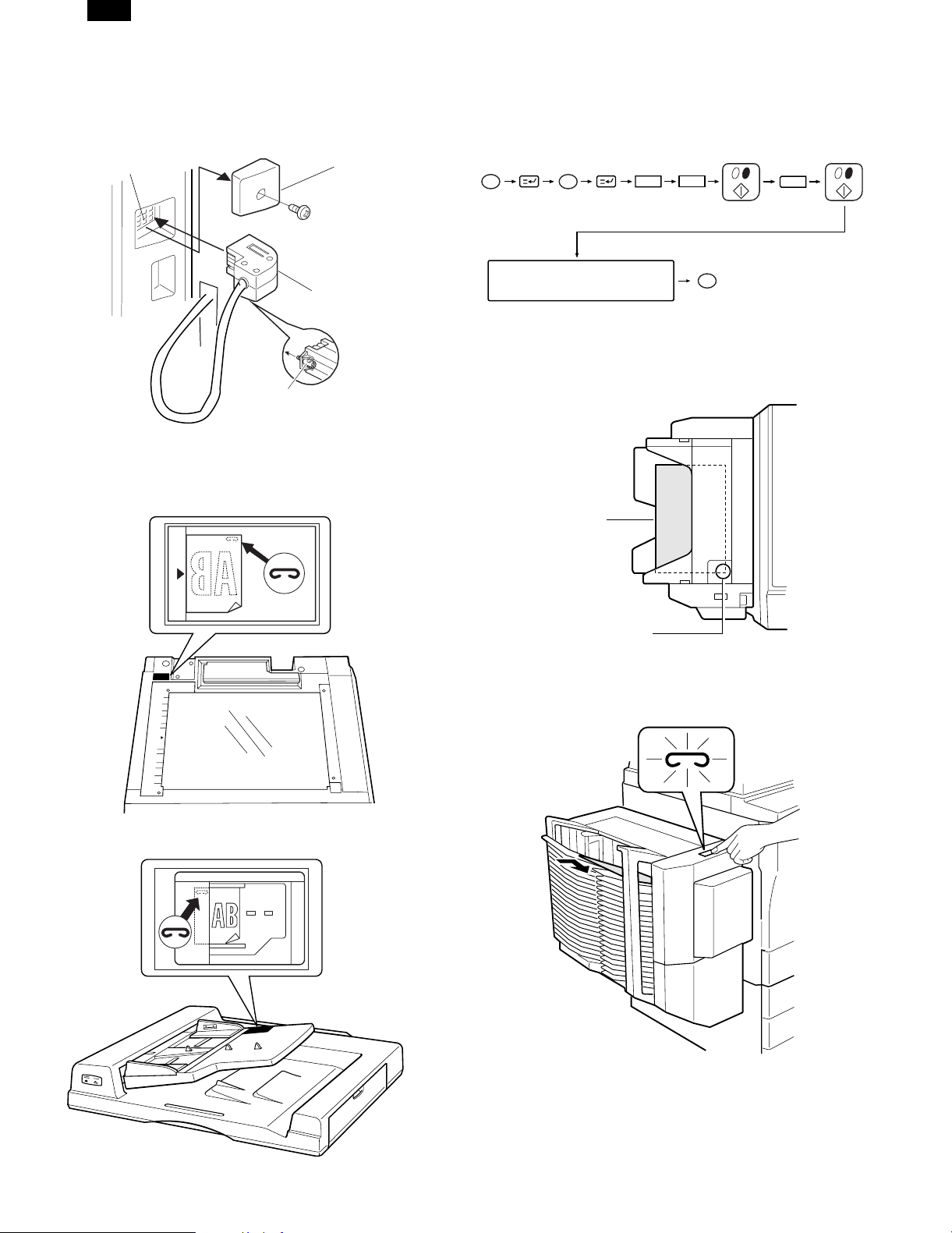
6. Connect the sorter connector.
Remove the sorter connector cover attached to the rear cabinet of the
copier.
Connect the sorter connector to the connector of the copier and
tighten the screw to fix the connector.
Connector of the copier
Sorter connector cover
Sorter connector
Screw
7. Attach the staple position label.
• Attach the staple position label as shown below.
Staple position label A (for the copier)
Insert the power plug of the copier into the power
outlet, turn on the power switch, and follow the
procedures below.
8. Set the mode.
• Set the mode with the key operation of the copier.
PC
Clear
Select the corresponding
number with the 10-key.
26
CA
The mode is set with the
above operations.
9. Check the operation of the staple sorter.
Align the paper to be stapled.
1
• The max. stapling capacity is 30 sheets. If the max. capacity is
exceeded, a malfunction may occur.
Copy (paper)
Staple position label D (for the RADF)
Stapling position
Set paper in the top bin, check the stapling position, and insert the
paper until it makes contact with the bin edge.
When the display lamp of the staple key is lighted, press the staple
key.
Remove the paper in the top bin, and check that stapling is made
properly.
If stapling is not made, repeat the above procedures.
With the above procedures, installation of the staple sorter is com-
pleted.
2 – 4
Page 7
AR-SS2
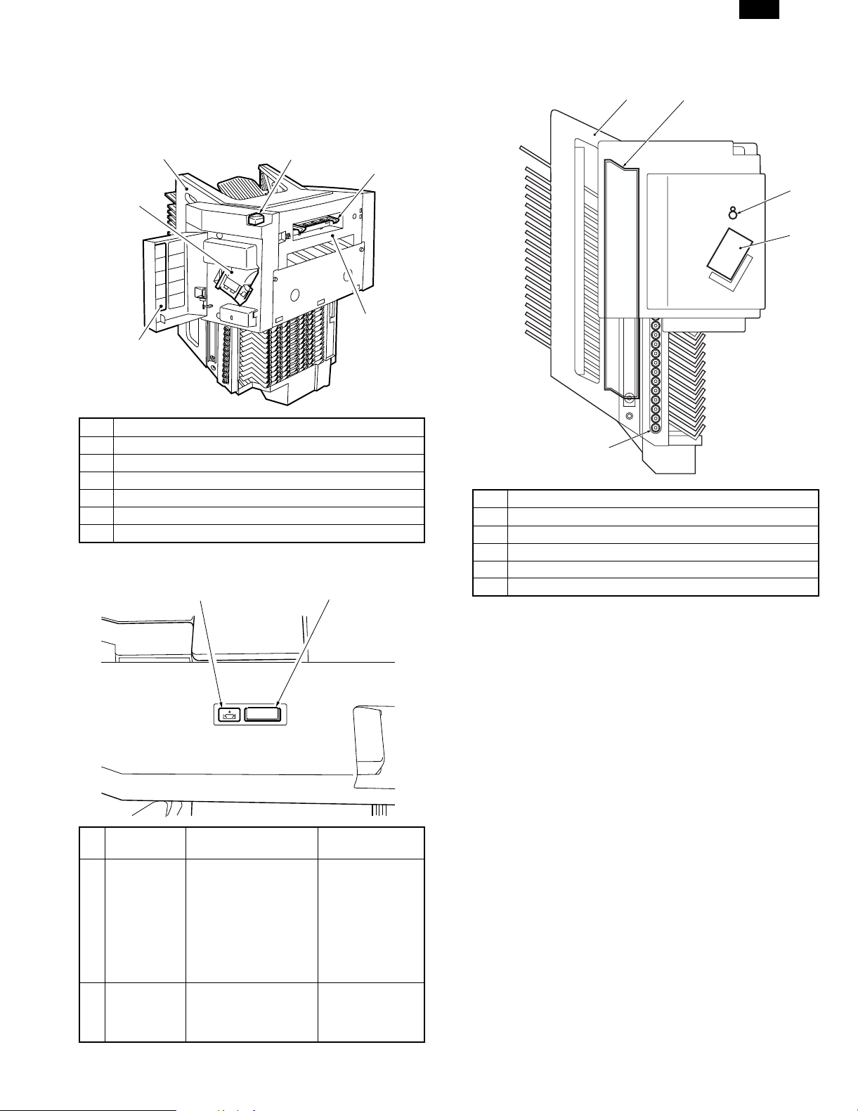
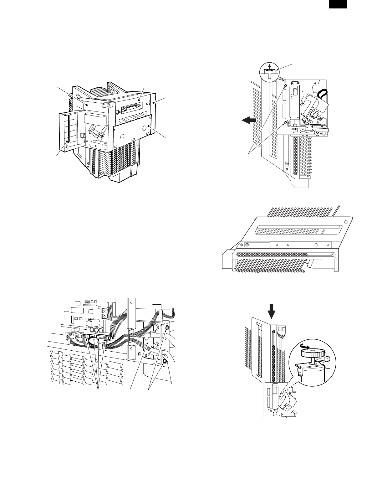
[3] EXTERNAL VIEW AND
INTERNAL STRUCTURE
1. Extern al par t s
1
3
2
No. Name
1 Bin unit
2 Stapler unit cover
3 Stapler unit
4 Transport guide unit
5 Latch lever
6 Latch
2. Operation panel
2
5
3. Cross section
1
6
4
3
No. Name
1 Bin unit
2 Guide bar
3 Roller
4 Stapler unit
1
5 Transport roller
2
5
4
No.
Key name Function Remarkl
1 Staple key • Press to start manual
stapling or manual
paper feed stapling.
• When pressed during
stapling, the
operation is stopped.
• Blinks when a staple
jam occurs.
2 Staple supply
display
Lights up when staplers
are exhausted.
During manual
paper feed
stapling,
interruption cannot
be made.
When the number
of remaining
staplers is 40 pcs
or less.
3 – 1
Page 8
AR-SS2
4. Sensors
PI5
PI4
PI9
PI8
PI7
Symbol Name Code Function
Sens or in bin (Light
emitting)
Sensor in bin (Light
receiving)
Bin unit shift motor
clock sensor PI1
Lead cam home
position sensor
Guide bar home
position sensor
Bin unit upper limit
sensor
Bin unit lower limit
sensor
Joint sensor PI6 Detects the joint.
Stapler unit cover
sensor
Staple home position
sensor
Staple ready sensor
Paper exit sensor PS1 Detects paper exit.
S1
PS1
PI3
S2
Detects paper in the
S1
bin (Light emitting)
Detects paper in the
S2
bin (Light receiving)
Detects clock signals
from the bin shift
motor.
Detects the lead cam
PI2
in the home position.
Detects the guide bar
PI3
in the home position.
Detects the bin unit at
PI4
the upper limit.
Detects the bin unit at
PI5
the lower limit.
Detects opening of
PI7
the stapler cover.
Detects stapling in
PI8
the home position.
Detects the first
PI9
staple at the
operation position.
PI2
PI1
PI6
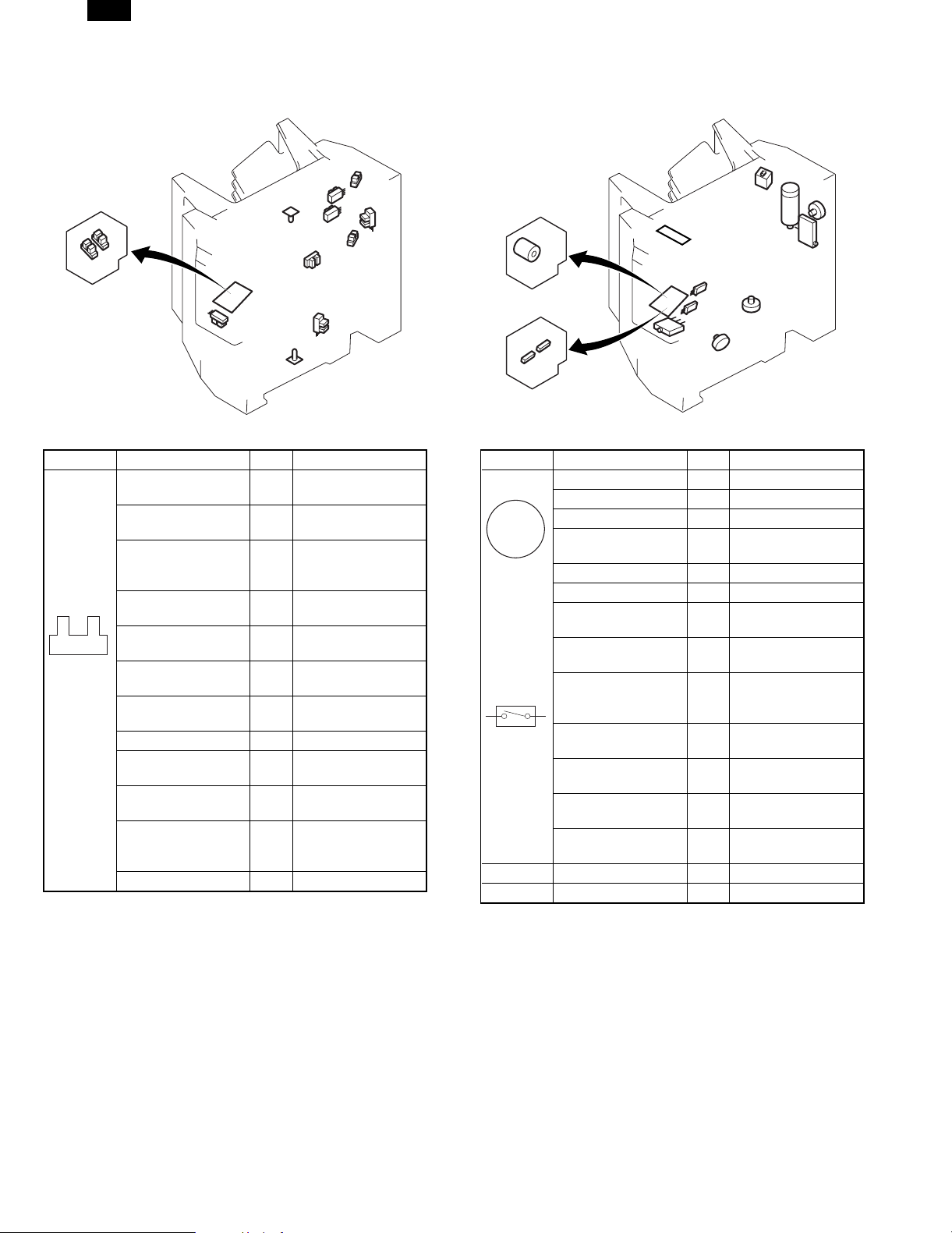
5. Motors, switches, solenoids and PCBs
MS8
M1
M2
SW
M5
MS5
MS6
Symbol Name Code Function
Bin unit shift motor M1 Shifts the bin.
Paper feed motor M2 Feeds paper.
Guide bar drive motor M3 Drives the guide bar.
M
Stapler unit oscillation
motor
Stapler motor M5 Drives the stapler.
Joint switch MS1 Detects the joint.
Stapler unit cover
switch
Stapler safety
detection switch
Stapler unit oscillation
home position sensor MS4
No staple detection
switch
Cartridge detection
switch
Obstacle detection
switch
Manual staple switch
MS3
MS4
MS2
MS2
MS3
MS5
MS6
MS8
M3
M4
Drives the stapler unit.
M4
Detects opening of
the stapler cover.
Detects staplers
under the safety state.
Detects the stapler
unit in the oscillation
home position.
Detects stapler empty.
Detects the stapler
cartridge.
Detects an obstacle.
Manual stapling
SW
operation
1 Control panel PWB
2 Sorter controller PWB
MS1
3 – 2
Page 9
AR-SS2
[4] DISASSEMBLY AND ASSEM BLY
1. External fitting
To clean, check, or repair the machine, remove the cover of the
desired section in the following procedures.
For the covers that can be removed simply by removing the fixing
screws, the procedures are omitted.
1
4
1 Front cover (2)
2 Right cover (2)
3 Rear cover (2)
4 Stapler unit cover
5 Transport guide unit
Note When removing the front cover, be careful not to break the
connector that is at the back of the operation panel.
5
3
2
4) Remove the two screws (4) on the front side and the two on the
rear side.
5) Lift the projection (5) of the accuride rail and remove the bin unit in
the arrow direction.
Note: Bin unit weight: About 10kg
5
4
6) Set down the removed bin unit as shown below.
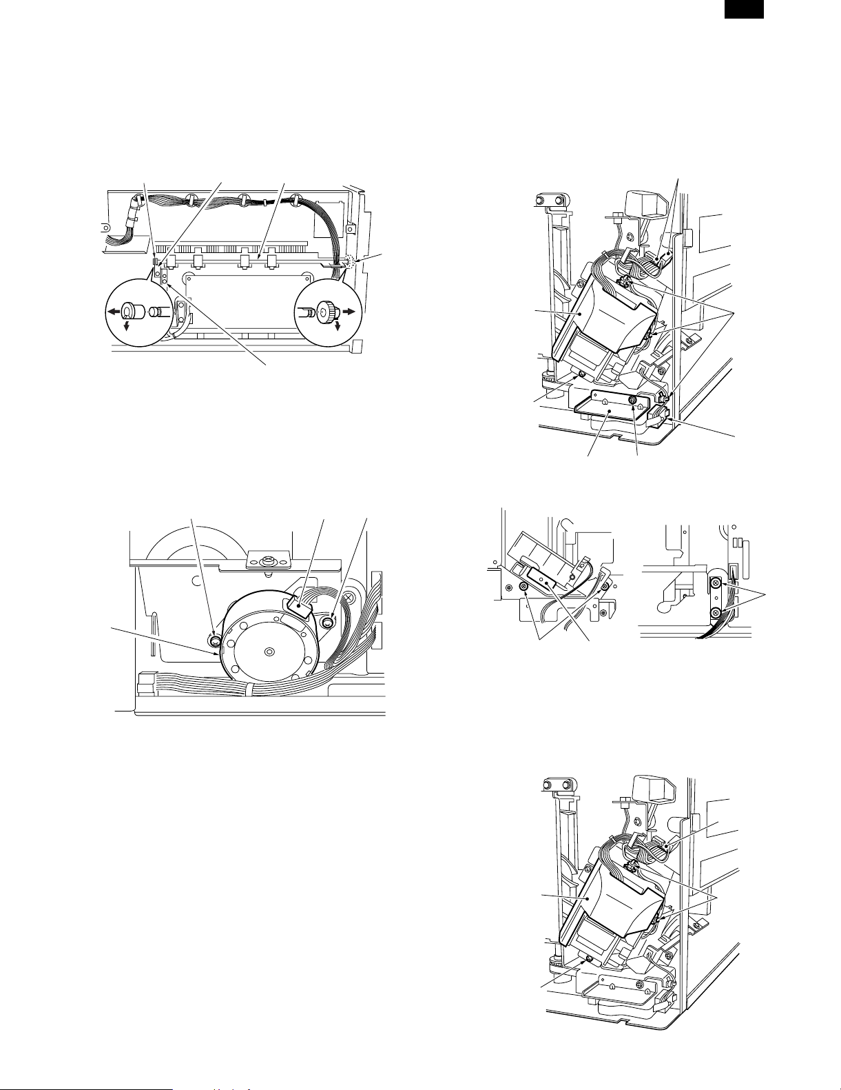
2. Bin unit
A. Bin unit removal
1) Remove the front cover, the right cover, and the rear cover.
2) Remove the four connectors (1) of the sorter controller PWB.
3) Remove the two screws (3) of the signal code plate (2), and
remove it.
1
2
3
Note: When assembling the bin unit, place the bin unit on the lead
cam from the upper side of the sorter body, rotate the clock
disc of the shift motor to engage the lead cam with the bin.
4 – 1
Page 10
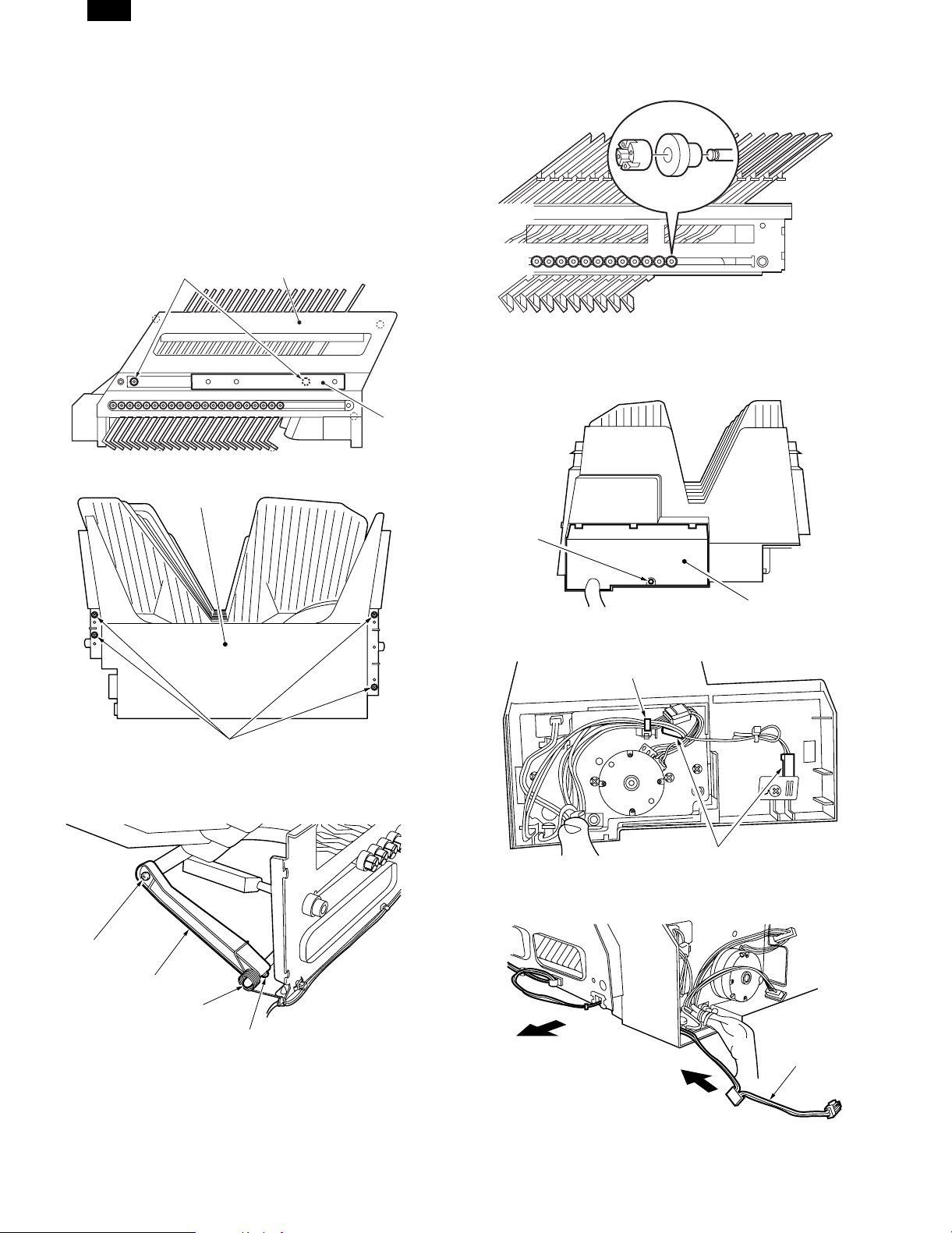
AR-SS2
B. Bin removal
When removing the bin of this machine, remove the bin roller. If,
however, it is removed twice or more, the strength will be decreased
and it must be replaced. For replacement of first bin to 13th bin,
replace from the top. For replacement of the lower bins, replace from
the bottom.
1. Replacement of bins from the top
1) Remove the bin unit from the sorter and lay it on a work table.
2) Remove the two screws (2) and remove the accuride rail (1).
3) Remove the three screws on the front and the four screws on the
rear, and remove the bin front cover (3).
3
4) Remove the four screws (5) and remove the bin upper cover (4).
4
2
1
6) Remove the bin roller stopper (9) and the bin roller (10), and
remove the bin.
2. Replacement of bins from the bottom
1) Remove the screw (2) of the bin lower unit cover (1), and then
remove the bin lower unit cover.
5
5) Remove the spring (7) and the screw (8), and then remove the
guide bar holder (5).
8
6
2
1
2) Remove the tie lap (3) and two connectors (4).
3
4
3) Pull out the sensor wiring (5) in the arrow direction.
7
8
5
4 – 2
Page 11
AR-SS2
4) Remove the two screws (7) of the guide bar holder (6).
67
5) Remove the four screws (9) and remove the bin lower unit (8).
When removing, separate the guide bar holder from the guide bar.
9
8
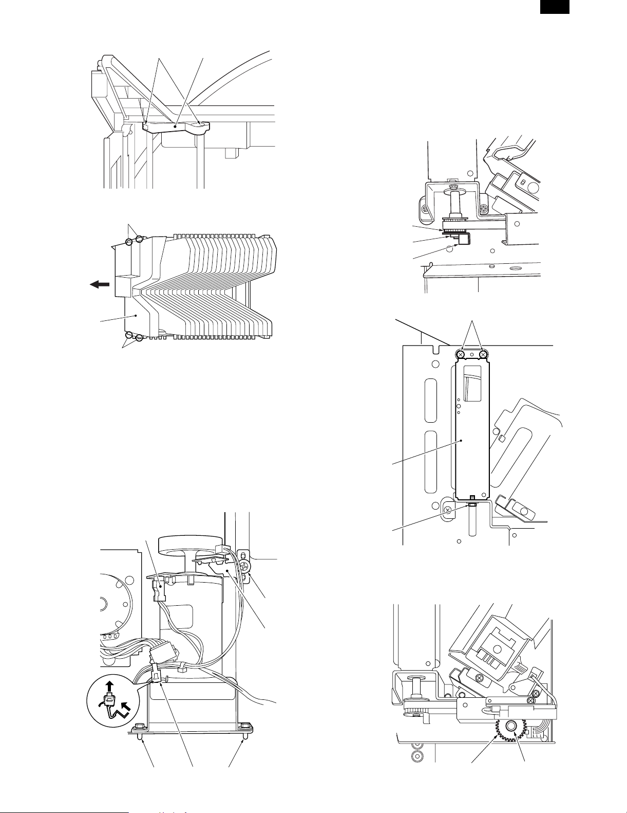
D. Lead cam
1. Lead cam removal
1) Turn on the power of the copier. Press SW2 on the sorter controller PWB to move the bin unit to the bottom.
Note: If two lead cams on the front and the rear sides are pressed
simultaneously, the bin unit falls suddenly. To prevent against
this, be sure to press them one at a time.
2) Remove the E-ring (1), the sensor flag (2), and the gear (3).
3
1
2
3) Remove the three screws (4), and remove the lead cam unit (5).
4
9
6) Remove the bin roller stopper and the bin roller, and remove the
bin.
Note: When assembling the bins, check the bin roller stopper lock
section. If it is broken, replace it. After assembling the bin unit,
check that all bin roller stoppers are in position.
C. Bin shift motor (M1) removal
1) Remove the rear cover.
2) Remove the screw (2) of the transport motor clock sensor mounting plate, and then remove the transport motor clock sensor
mounting plate (1).
3) Remove the connector (3), and pull out the tie lap(4) from the hole
in the plate.
4) Remove the two screws (5), and remove the bin shift motor.
3
2
1
5
4
2. Lead cam position adjustment
1) Remove the E-ring (2) of the lead cam drive gear (1) on the front
side.
455
4 – 3
1
2
Page 12
AR-SS2
2) Adjust engagement of the lead cam drive gear (1) so that the
upper blade tips of the lead cams on the front and the rear sides
are as shown in the figure below.
3) Attach the E-ring.
Note: When assembling the flag (1) for the lead cam home position
sensor, fit the teeth tips (2) of the lead cam with the phase of
the flag (1) as shown below.
2
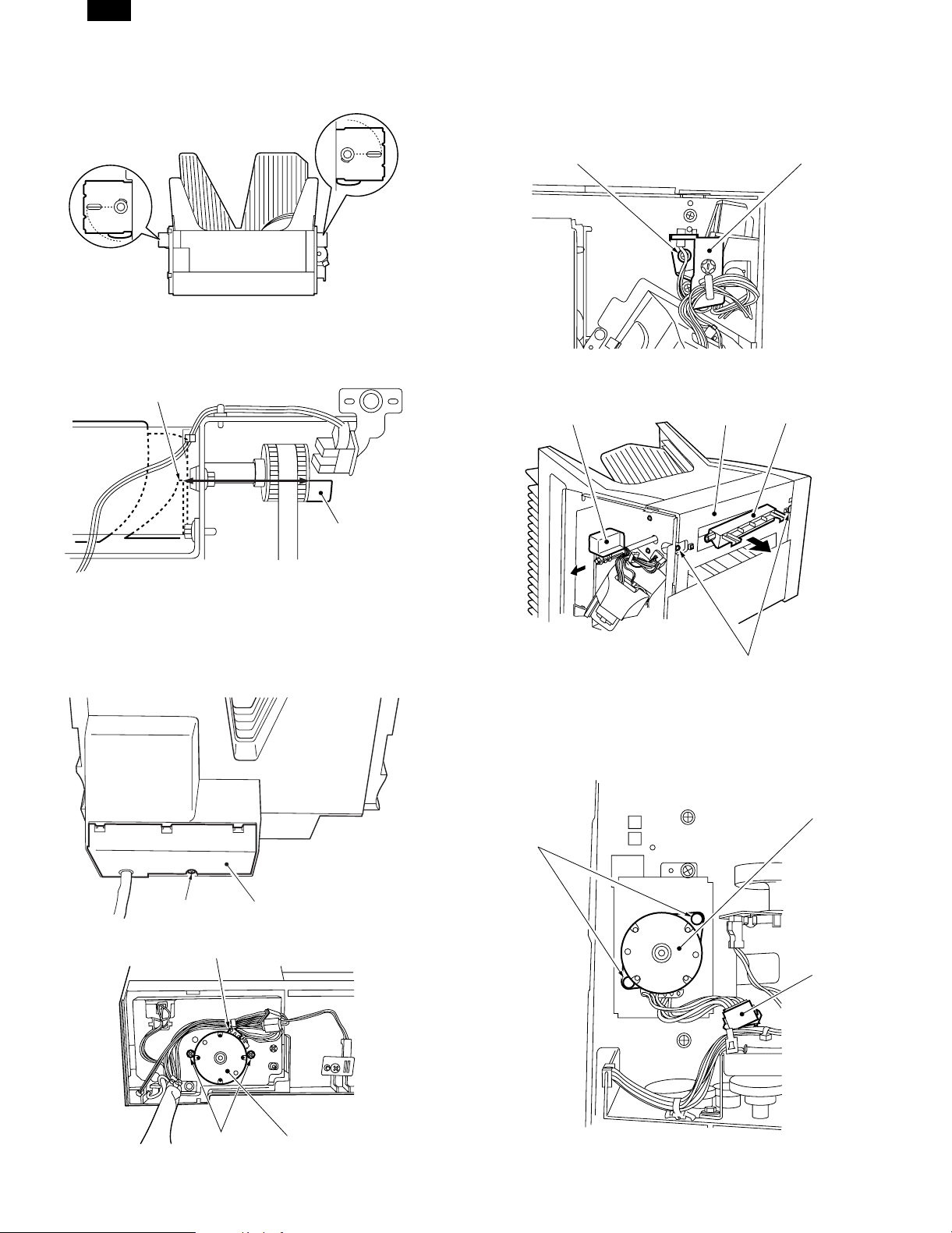
3. Transport duide
A. Transport guide unit removal
1) Remove the front cover.
2) Remove the screw (2) and the latch lever holder (1).
2
3) Remove the latch lever (3) and the latch (4).
4) Remove the screw (5), and remove the transport guide unit (6).
3
6
1
4
1
E. Guide bar motor (M3) removal
1) Lift the bin unit to the top for easiness of work.
2) Remove the screw (1) and remove the bin lower unit cover (2).
3) Remove the connector (3) and two screws (4), and then remove
the guide bar motor (5).
1
2
3
5
B. Transport motor (M2) removal
1) Remove the rear cover.
2) Remove the connector (1) and two screws (2), and then remove
the transport motor (3).
3
2
1
4
5
4 – 4
Page 13
AR-SS2
C. Transport roller removal
1) Remove the right cover, the front cover, the transport guide unit,
the rear cover, and the transport motor.
2) Remove the transport roller bushing (1) and the gear (2).
3) Remove the screw (3), and remove the transport roller attachment
fixture (4).
4) Remove the transport roller (5).
1
4
5
2
3
4. Stapler oscillation unit
A. Stapler unit oscillation motor (M4) removal
1) Remove the right cover.
2) Remove the connector (1) and two screws (2), and remove the
stapler unit oscillation motor (3).
2
1
2
B. Stapler oscillation unit removal
1) Remove the right cover, the stapler unit oscillation motor, and the
front cover.
2) Remove the three connectors (1) and three tie laps (2).
3) Remove the screw (3), and remove the stapler unit (4).
4) Remove the screw (5), and remove the stapler cover switch unit
(6).
1
4
3
6
5) Remove the four screws (7), and remove the stapler oscillation
unit (8) toward you.
5
2
1
7
3
7
8
5. Stapler unit
A. Stapler unit removal
1) Remove the front cover.
2) Remove the connector (1) and two tie laps (2).
3) Remove the screw (3), and remove the stapler unit (4).
1
4
3
2
4 – 5
Page 14
AR-SS2
[5] ADJUSTMENTS
1. Electrical syst em
A. Process for major parts replacement
Major parts Process
• Sorter controller PWB 1) Bin paper sensor sensitivity
adjustment
2) Guide bar motor oscillation range
adjustment
3) Stapler oscillation motor oscillation
range adjustment (Staple position
adjustment)
• Bin paper sensor (S1,
2)
• Guide bar home
position sensor (PI3)
• Guide bar oscillation
motor (M3)
• Stapler oscillation
motor (M4)
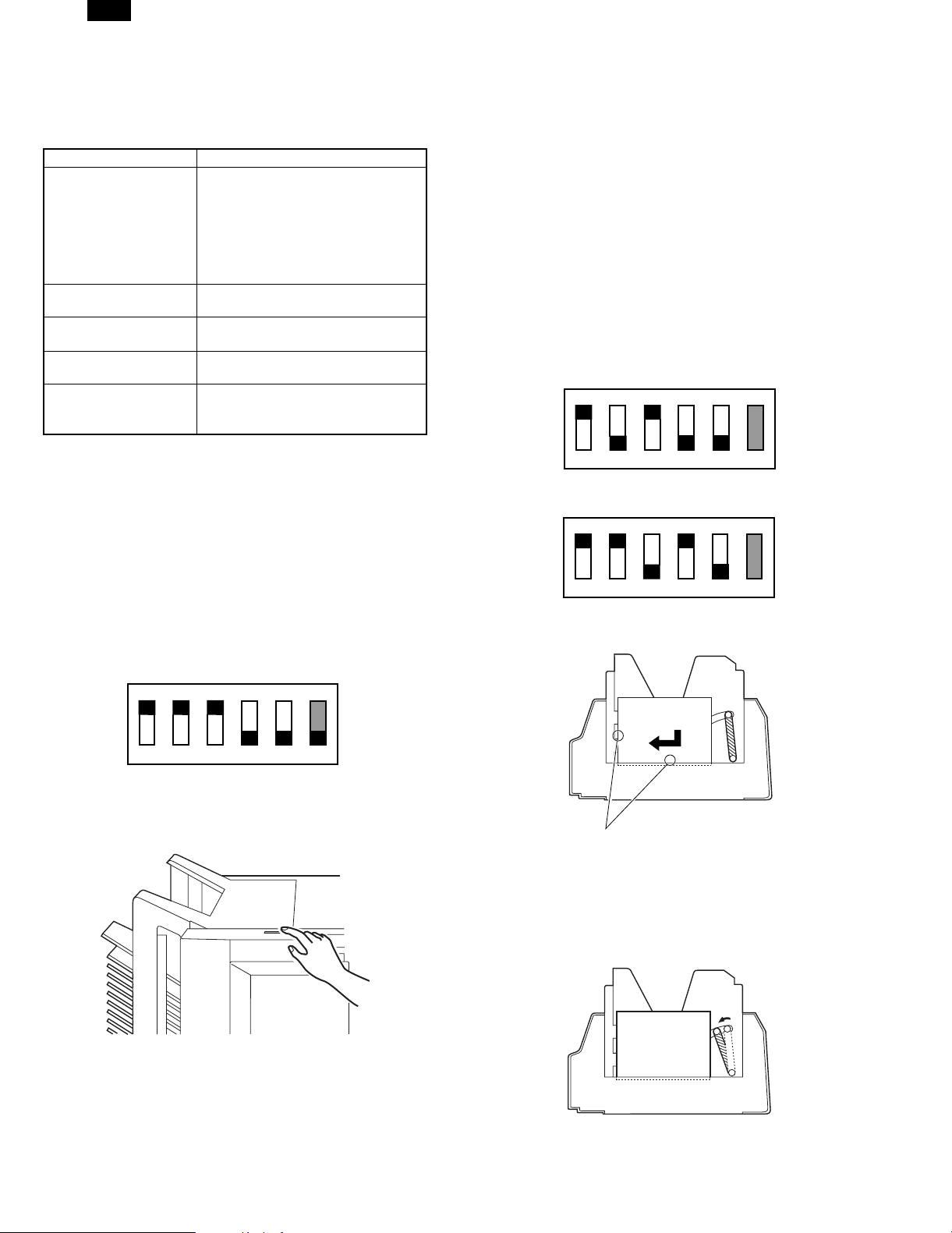
B. Bin paper sensor sensitivity adjustment
This adjustment must be performed when replacing the following
parts:
• Sorter controller PWB
• Bin paper sensor (S1, S2)
Note: To perform this adjustment, the bin unit must be assembled
completely in advance. If the adjustment is performed without
assembling the cover, etc., the sensor will receive external
lights, resulting in an error in adjustment.
<Operating procedure>
1) Remove all the paper in the bins.
2) Remove the right cover, and set the DIP switch on the sorter
controller PWB as shown below.
1) Bin paper sensor sensitivity
adjustment
1) Guide bar motor oscillation range
adjustment
1) Guide bar motor oscillation range
adjustment
1) Stapler oscillation motor oscillation
range adjustment (Staple position
adjustment)
5) When the manual staple key blinks, turn off and on the copier
power switch, check the status of the bin paper sensor (on the
light emitting side and the light receiving side) corresponding to
the error code, and perform the adjustment from procedure 1)
again.
6) After completion of the adjustment, return the DIP switch on the
sorter controller PWB to the original state.
C. Guide bar oscillation range adjustment
This adjustment is performed when the following parts are replaced.
• Sorter controller PWB
• Guide bar home position sensor (PI3)
• Guide bar oscillation motor (M3)
<Operating procedure>
1) Prepare one sheet of A4 or letter paper for copying.
2) Remove all the paper from the bins.
3) Remove the right cover, and set the DIP switch (SW1) on the
sorter controller PWB as shown below. (Note that the setup content differs depending on the copy paper size.)
ON
∗1
123456
(When A4 copy paper is used)
ON
∗1
123456
(When letter copy paper is used)
4) Place A4 or letter copy paper in the bin as shown below.
ON
123456
∗ Do not move No. 6, which is used only for selection of the com-
munication system with the copier.
3) Press the manual staple key on the operation section of the
machine.
4) Check the status of the manual staple key on the operation section of the machine.
ON: Adjustment completed.
Blinking: Adjustment error
In case of an adjustment error, the error code of F1-91 is dis-
played on the copier.
A4/Letter
Make close contact.
5) Operate the bin shift key (SW2, SW3) on the sorter controller
PWB to bring the guide bar into a slight contact with the copy
paper.
UP key (SW3): Moves the guide bar to the paper.
DOWN key (SW2): Moves the guide bar apart from the copy
paper.
Copy paper
6) Under the state of procedure 4), press the manual staple key on
the operation section of the machine. The guide bar returns to the
home position and the adjustment value is stored.
5 – 1
Page 15
AR-SS2
7) Check the status of the manual staple key.
ON: Adjustment completion
Blinking: Adjustment error
8) When the manual staple key blinks, check the installing condition
of the guide bar home position sensor, and perform the adjustment from procedure 4) again.
9) After completion of the adjustment, return the DIP switch (SW1)
on the sorter controller PWB to the original state.
D. Stapler unit oscillation position adjustment
(Staple position adjustment)
This adjustment is performed when the following parts are replaced.
• Sorter controller PWB
• Stapler unit oscillation motor
• Stapler oscillation unit
<Operating procedure>
1) Remove all the paper from the bins. Remove the right cover.
2) Set the DIP switch (SW1) on the sorter controller PWB as shown
below.
SW2 SW3
SW1LED
ON
1
123456
3) Place 5 sheets of A4 or letter paper in the first bin as shown
below.
4) Press the push switch (SW3) on the sorter controller PWB to shift
the stapler oscillation unit to the stapling position.
5) Press the push switch (SW2) on the sorter controller PWB and
press the manual staple key to staple and check the stapling
position.
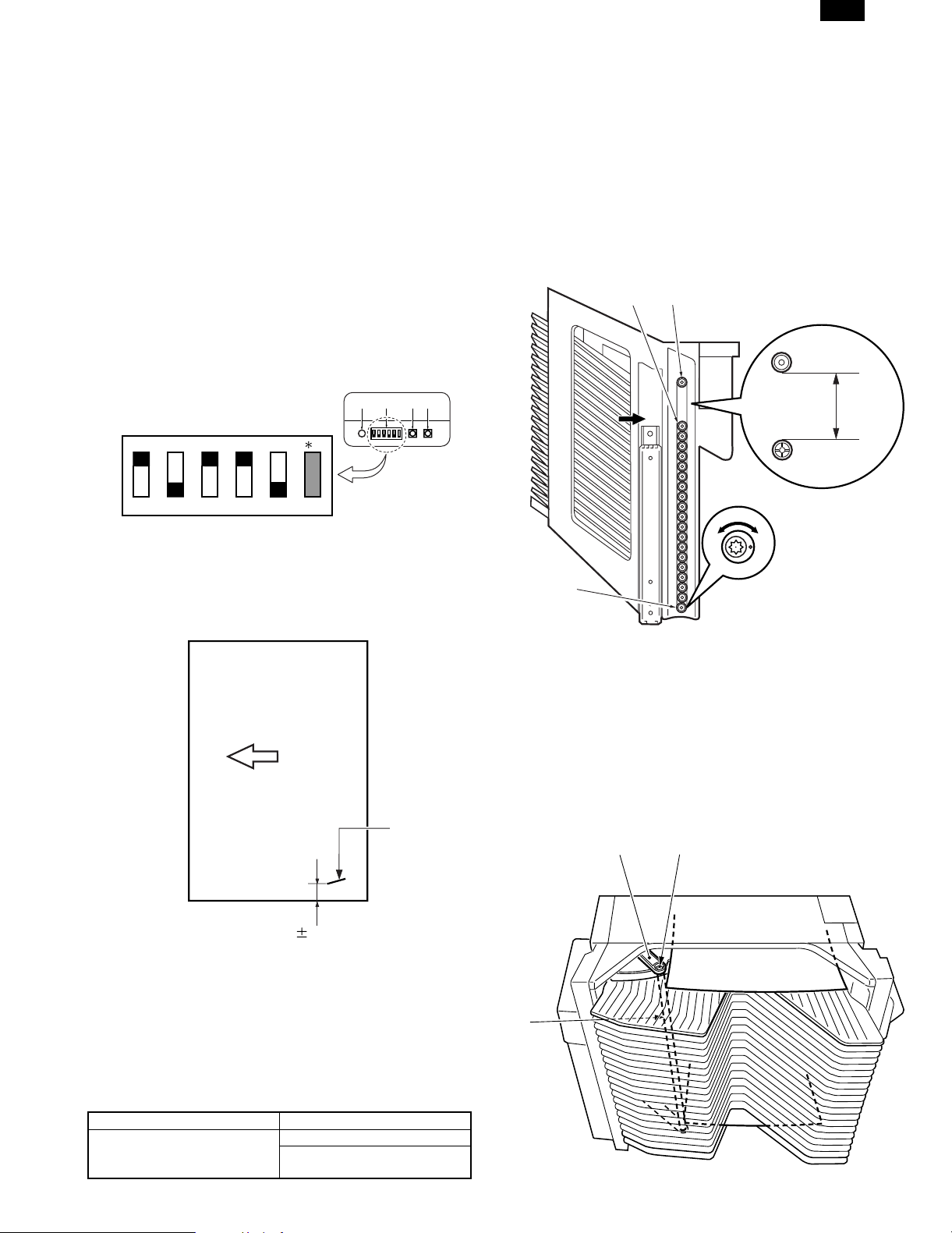
B. Bin roller height adjustment
The dummy roller lower is of eccentric shape so that you can adjust
the height of the bin roller this is so you can adjust the height at which
the bin roller and the lead cam tip t ouch.
When the bin roller is replaced or reassembled, check the standard
dimensions and change and adjust the installing angle of the dummy
roller lower if necessary.
1) Adjustment procedure
Stand up the bin unit straight. Measure the distance between the
upper dummy roller (1) and the bin roller (2). If the distance is too
large, rotate the lower dummy roller (3) counterclockwise. If the
distance is too small, turn it clockwise. Turn and adjust so that the
distance is about 97.8mm.
1
2
97.8mm
3
Transport direction
Staple
6 2.5mm
6) If the stapling position is outside the specified range, adjust the
stapling position with the push switch (SW3).
Press the staple key of the sorter. The stapler oscillation unit
returns to the home position and the adjustment value is stored.
7) Return the DIP switch (SW1) to the original state and install the
right cover.
2. Mechanical system
A. Process for major parts replacement
Major parts Process
Bin, bin roller 1) Bin roller height adjustment
2) Guide bar parallelism
adjustment
3. Guide bar parallelism adjustment
When the bin unit is disassembled or the top screw of the guide bar is
removed, adjust the guide bar parallelism.
1) Adjustment procedure
Set B5 paper or A4R paper in the 1st bin and in the 20th bin.
Push the guide bar (1) manually in the alignment direction to press
it onto the paper.
Check contact conditions of the guide bar and the paper in the 1st
bin and the 20th bin. If they are not parallel, loosen the screw (3)
of the guide bar holder (2).
2
1
3
5 – 2
Page 16

AR-SS2
[6] DIAGNOSTICS
1. PWB
SW2 SW3
SW1LED
2. List of DIP switch functions
The functions of the DIP switch (SW1) on the sorter controller PWB
are as follows:
Purpose DIP switch setup Content
Normal copy state • When all are set to OFF, the machine returns to the normal mode.
ON 1
123456
Transport motor (M2) • When the manual staple key (SW) is pressed, the transport motor (M2)
ON
1
rotates forward (in the paper transport direction). To stop the motor,
press the manual staple key (SW) again.
123456
Sensor adjustment mode (Bin
paper sensor)
Guide for operation range
adjustment mode (When A4
size is used)
ON
123456
ON
• When the manual staple key (SW) is pressed, adjustment of the bin
1
paper sensors (S1, S2) is performed. (For details, refer to page 5-1)
Adjustment complete: Manual staple key (SW) ON
Adjustment error: Manual staple key (SW) blinking
In case of an adjustment error, check which sensor is malfunctioning by
the error code.
Error code F1-91: S1, S2 error
• For details, refer to page 5-1.
1
123456
Guide bar operation range
adjustment mode (When letter
size is used)
ON
• For details, refer to page 5-1.
1
123456
Guide bar operation text • When the manual staple key (SW) is pressed, the guide bar operates.
ON
1
The operation of A4R -> B5 -> Letter R -> A4R is repeated. When the
manual staple key is pressed again, the guide bar returns to the home
position.
123456
Stapler unit oscillation position
adjustment
ON
• For details, refer to page 5-2.
1
123456
∗1: Do not move No. 6 of DIP switch, which is used only for selection of the communication system with the copier.
(ON: Now IPC communication / OFF: Old IPC communication)
6 – 1
Page 17

AR-SS2
3. Self diagnostics
This machine is provided with the self diagnostics function of the
machine state by the CPU (Q1) on the sorter controller PWB. It
performs diagnostics occasionally and displays an error message or
code on the copier when any abnormality is found.
A. Stack over alarm
Abnormality Copier operation Reset
Overload
(When the capacity
per bin is exceeded
during copying)
B. Stapler alarm
Abnoamality Copier operation Reset
Staple jam • Staple sort mode:
Stapler safety
mechanism
operating ( foreign
material is in the
stapler)
Staple capacity
over (The load
quantity per bin
exceeds the max.
stapling capacity
(30 sheets) in the
staple sort mode.)
Mixed paper sizes
(horizontal
direction)
No staple • Staple sort mode:
C. Jam
Abnormality Copier function
Transport delay jam
Refer to page 9-8.
Transport remaining jam
Refer to page 9-8.
Power ON jam
Refer to page 9-8.
Door open jam
Refer to page 9-8.
■ Reset
After processing a jam, turn on the joint switch (MS1)
• Standby state (Start
key OFF)
Alarm display is
made when the copy
start key is pressed.
Copying is disabled.
• Other mode
Normal operations
• Staple sort mode:
Alarm display is
made when the copy
start key is pressed.
Copying is disabled.
• Other mode
Normal operations
• Staple sort mode:
Alarm display is
made when the copy
start key is pressed.
Copying is disabled.
• Other mode
Normal operations
• Staple sort mode:
Alarm display is
made when the copy
start key is pressed.
Copying is disabled.
• Other mode
Normal operations
Alarm display is
made when the copy
start key is pressed.
Copying is disabled.
• Other mode
Normal operations
Operation stop
Operation stop
No operation
Operation stop
Remove all the
paper in the bins.
Remove the
jammed staple and
close the stapler
unit.
Open and close
the stapler unit
cover.
Remove all the
paper from the bins.
Remove all the
paper from the bins.
Set a new staple
cartridge.
D. Error
Sub
code
Content The power source (+24V) is not supplied.
Description
• The +24V power is not supplied to the sorter
80
Detail
control PWB.
• The breaker is shut off.
• The +24V power detection circuit trouble
• The +24V line in the sorter control PWB is
checked.
Content Staple unit oscillation motor (M4) lock
• When the stapler unit moves from the
oscillation home position, the stapler unit
oscillation home position switch is kept ON
after 50 pulses.
• When the stapler unit moves to the oscillation
home position, the stapler unit oscillation home
87
Detail
position switch is kept OFF for 2 sec.
• Stapler unit oscillation motor trouble
• Stapler unit oscillation home position switch
trouble
• Circuit breaker operation
• Stapler unit oscillation mechanism trouble
• Sorter controller PWB trouble
• Check the operations of the stapler shift motor
and the sensor with SIM 3-1/2.
Content Bin shift motor lock (M1)
• The operation is not completed in the time
which is 4 times greater than the specified time
after starting the bin shift motor.
• When driving the bin shift motor, the signal
from the shift motor lock sensor is not detected
for 250msec.
89
Detail
• When shifting to the home position, the
operation is not completed in 20 sec.
• Bin shift motor trouble
• Lead cam home position trouble
• Bin shift mechanism trouble
• Circuit breaker operation
• Sorter control PWB trouble
• Check the operation of the bin shift motor and
the sensor with SIM 3-1/2.
Content Bin paper sensor automatic adjustment trouble
• The sensor output abnormality in the sensor
91
Detail
detection level adjustment
• Bin paper sensor trouble
• Sorter control PWB trouble
• Check the sensor output with SIM 3-2.
Content • Manual staple key abnormality
• When copying is started with the bin in the
home position and while the manual staple key
94
Details
is kept pressed in a mode other than the
non-sort mode, and when pressing of the
manual staple key is detected for 5 sec.
• Manual staple key trouble
• Operation PWB trouble
6 – 2
Page 18

AR-SS2
[7] TROUBLESHOOTING
1. Troubleshooting procedures
A. F1-91/Display ON
Cause/
Trouble position
Cable 1 Check that the cable between the sorter controller
Cable 2 Check that the cable between the bin paper
Installation of bin paper
sensor light emitting side
(S1) and light receiving
side (S2)
Bin paper sensor light
emitting side (S1) and light
receiving side (S2)
Sorter controller PWB NO Replace the sorter controller PWB, and perform the bin paper
B. F1-87/Display ON
Cause/
Trouble position
Circuit breaker 1 Check that the circuit breaker on the sorter
24V power is not supplied 2 Set the tester range to 50VDC. Check that the
Stapler unit oscillation
motor (M4)
Stapler unit oscillation
motor home position
switch (MS4)
Sorter controller PWB Replace the sorter controller PWB, and perform the bin paper
Procedure Check item Result Process
PWB and the bin unit is properly connected.
sensor light emitting side (S1) and the light
receiving side (S2) is properly connected.
3 Check that the bin paper sensor light emitting side
(S1) and the light receiving side (S2) are properly
installed.
4 When the bin paper sensor light emitting side (S1)
and the light receiving side (S2) are replaced and
the bin paper sensor sensitivity adjustment is
performed, the trouble is canceled.
Procedure Check item Result Process
controller PWB is operating.
voltage between J1-1 (+) and J1-2 (–) on the
sorter controller PWB is about 24V.
3 Check that there are pulse outputs at connector
J12-2 to -5 on the sorter controller PWB at the
operating timing of the stapler unit oscillation
motor.
Check that J12-1 is +24V.
4 Set the tester range to 50VDC. Check that the
voltage between the sorter controller PWB J6-3
(+) and the case (–) is about 24V (when the joint
and the coupler are closed). Check that the
voltage between J6-4 (+) and the case (–) is
about 24V when the stapler oscillation unit is in
the home position, and 0V when it is not.
NO Connect properly.
NO Connect properly.
NO Connect properly.
When the bin paper sensor light emitting side (S1) and the light
receiving side (S2) are installed again, perform the bin paper
sensor sensitivity adjustment. (For the procedure, refer to page
5-1)
YES Replace the bin paper sensor light emitting side (S1) and the
light receiving side (S2) and perform the bin paper sensor
sensitivity adjustment. (For the procedure, refer to page 5-1)
sensor sensitivity adjustment, the guide bar motor oscillation
range adjustment, and the stapler motor oscillation motor
oscillation range adjustment. (For the procedures, refer to pages
5-1 to 5-2)
YES Remove the cause of the circuit breaker operation, and press the
circuit breaker.
NO Check 24V of the copier.
YES Check the wiring to the stapler unit oscillation motor. If it is
normal, replace the stapler unit oscillation motor.
YES Stapler unit oscillation motor home position switch (MS4)
sensor sensitivity adjustment, the guide bar motor oscillation
range adjustment, and the stapler oscillation motor oscillation
range adjustment. (For the procedures, refer to pages 5-1 to 5-2.)
C. F1-89/Display ON
Cause/
Trouble position
Cable 1 Check that the cable between the bin shift motor
Circuit breaker 2 Check that the circuit breaker (CB1) on the sorter
24V power is not supplied 3 Set the tester range to 50VDC. Check that the
Bin shift motor (M1) 4 Check that the voltage between the connector
Sorter controller PWB NO Replace the sorter controller PWB, and perform the bin paper
Procedure Check item Result Process
and the sorter controller PWB is properly
connected.
controller PWB is operating.
voltage between the sorter controller PWB J1-1
(+) and J1-2 (–) is about 24V.
J8-1 and J8-2 on the bin shift motor driver PWB is
about 24V at the operating timing of the bin shift
motor (M1).
NO Connect properly.
YES Remove the cause of the circuit breaker operation, and press the
circuit breaker.
NO Check the 24V power of the copier.
NO Check the wiring to the bin shift motor. If it is normal, replace the
bin shift motor.
sensor sensitivity adjustment, the guide bar motor oscillation
range adjustment, and the stapler oscillation motor oscillation
range adjustment. (For the procedures, refer to pages 5-1 to 5-2.)
D. F1-94 display ON
Cause/
Trouble position
The manual staple key is
pressed when starting
copying.
Key 2 Press a key and check that the switch on the
Operation PWB 3 Check the cable connection between the sorter
Procedure Check item Result Process
1 Check that there is anything on the key or not. NO Start copying in a mode other than the non-sort mode with the
bin in the home position to check that the operation is performed
normally or not.
NO Properly connect the cable.
operation PWB is pressed or not.
YES Replace the operation PWB.
control PWB and the operation PWB.
7 – 1
Page 19

[8] MAINTENANCE
1. Periodic replacement parts
There is no part which must be replaced periodically.
2. Consumable parts life
The following part may deteriorate or require replacement during the warranty period. Replace it if it is deteriorated or broken.
AR-SS2
No. Part name Part number
1 Stapler 0GZ4A12553000 1 Stapling 300,000 times One staple cartridge allows about
No. of part
used
Reference of life Remark
5,000 stampling.
3. Periodic services list
This machine has no part which requires periodic servicing.
8 – 1
Page 20

AR-SS2
[9] OPERATIONAL DESCRIPTIONS
1. Outline
This machine performs sorting and stapling of copy paper according
to the operation mode set by the copier.
Stapling is made also by the operation of the keys on this machine.
There are following four operation modes;
1. Non-sort mode
2. Sot mode
3. Group mode
4. Staple sort mode
2. Details
The basic operations in each mode are described below.
A. Non-sort mode
If the sort/group mode is not set, all copy paper is discharged to the
1st bin.
1) Press the copy start key of the copier.
↓
2) Copy paper is discharged to the 1st bin.
↓
↓
↓
↓
↓
↓
Non-sort mode (10 black/white sheets)
Copier resist
Paper exit sensor
Transport motor
Bin shift motor
Lead cam sensor
Bin lower limit sensor
Guide bar oscillation motor
Guide bar HP motor
Parrallel section HIGH
Pin HP LOW
↓
↓
↓
3) Copying of the set quantity is completed.
↓
4) Discharging of th e set qua ntity is comp leted and the o perat ion
is completed.
Forward rotation
Transport (Transport)
Alignment (Alignment)
Shift (Up)
Staple oscillation (Shifted to the stapling position.)
Staple (Staple)
Reverse rotation
Transport (Not)
Alignment (Save)
Shift (Down)
Staple oscillation (Shifted to HP.)
Staple (Staple jam reset)
• Sort mode (B/W, color): Discharged from the 2nd bin.
The other modes: Discharged from the 1st bin.
9 – 1
Page 21

AR-SS2
B. Sort mode
When the sort mode is set, alignment of copy pages is automatically
performed.
B/W mode Color mode
4) Copying of the specified quantity is completed.
↓
Black/white mode Color mode
1) Press the copy start key of the copier .
↓↓
↓
2) The guide bar is oscillated from the paper exit center to the half
of the paper size +8mm.
↓
Copy paper exit direction
↓
↓
↓
↓
↓
↓
↓
Guide bar
↓
↓
↓
↓
5) The orig in al is ch anged and reverse sort in g is performed.
↓
3) Every time paper is discharged, the guide bar oscillates to
press the paper to the regulation plate to align paper and the
bin is shifted by one.
↓
↓↓
Discharged copy paper
↓
↓
↓
↓
↓
↓
↓
↓
↓
↓
When the number of copy sets is 1 to 19, copies are discharged
from the 2nd bin.
When the number of copy sets is 20, copies are discharged from
the1st bin.
Sort mode (black/white, 2 originals, 3 copies)
Copier resist
Paper exit sensor
Transport motor
Bin shift motor
Lead cam sensor
Bin lower limit sensor
Guide bar oscillation motor
Guide bar HP motor
Sort mode (color, 2 originals, 3 copies)
Copier resist
Paper exit sensor
Transport motor
Bin shift motor
Lead cam sensor
Bin lower limit sensor
Guide bar oscillation motor
Guide bar HP motor
↓
↓
↓
6) The operation is repeated until all the originals are completed.
7) After comple tion o f copying , the gu ide bar returns to the h ome
position.
8) When copying is stopped, the bin which is not closed isshifted.
↓
↓
↓
↓
9 – 2
Page 22

AR-SS2
C. Group mode
When the group mode is set, the copies of an original set are discharged to one bin.
1) Press the copy start key of the copier.
↓
2) The guid e bar is oscillated f rom t h e pa per exit center to t he hal f
of paper size +6mm.
↓
↓
Paper exit center
↓
↓
↓
↓
3) Every time paper is discharged, the guide bar oscillates to
press the paper to the regulation plate to align paper and the
bin is shifted by one.
↓
Copy paper exit direction
Bin
Guide bar
6mm
Paper size
Discharged copy paper
5) The or iginal is changed and th e bin is shift ed by one.
↓
↓
↓
↓
↓
↓
6) The operation i s repeated until all the originals are completed.
↓
7) After completion of copying, the guide bar returns to the home
position.
Copies are loaded from the 1st bin to the 20th bin sequentially.
When the original exceeds 20 pages, loading is returned to the1st
bin without reverse sorting.
↓
↓
↓
↓
4) Copying of the specified quan tity is completed.
↓
Group mode (black/white, 3 originals, 2 copies)
Copier resist
Paper exit sensor
Transport motor
Bin shift motor
Lead cam sensor
Bin lower limit sensor
Guide bar oscillation motor
Guide bar HP motor
9 – 3
Page 23

AR-SS2
D. Staple sort mode
When the staple mode is set, stapling is automatically performed after
sorting the copies.
1) The sa me operatio ns as the sort mod e are performed an d all
copied papers are discharged to the bins.
↓
↓
↓
↓
↓
↓
2) The guide bar oscillates.
↓
↓
↓
Discharged paper
4) The stapler unit staples the paper.
↓
5) The guide bar, the paper holding arm, and the stapler unit are
separated from the paper.
↓
6) The bin is shifted by one.
↓
↓
↓
↓
↓
7) Proc edures 3 to 6 are repeated for al l paper in the bins, and the
operation is completed.
Note: The staple sort mode is valid only when the RADF is used. In
the book mode, the staple sort mode can be set, but automatic
stanpling cannot be performed.
Paper holding arm
↓
3) The guide bar aligns the paper.
The stapler unit is shifted to the stapling position.
At the same time, the paper holding arm holds discharged
paper.
↓
Discharged paper
↓
↓
↓
↓
Stapler unit
Paper holding arm
Paper
Bin
Bin supporting arm
9 – 4
Page 24

AR-SS2
Staple sort mode (Black/white, 2 originals, 3 copies)
Copier resist
Paper exit sensor
Transport motor
Bin shift motor
Lead cam sensor
Bin lower limit sensor
Guide bar oscillation motor
Guide bar HP motor
Staple motor
Stapler oscillation motor
Stapling HP sensor
Stapler oscillation HP sensor
Staple sort mode (Color, 2 originals, 3 copies)
Copier resist
Paper exit sensor
Transport motor
Bin shift motor
Lead cam sensor
Bin lower limit sensor
Guide bar oscillation motor
Guide bar HP motor
Staple motor
Stapler oscillation motor
Stapling HP sensor
Stapler oscillation HP sensor
9 – 5
Page 25

AR-SS2
3. Operations of each section
A. Transport drive system
(1) Outline
The transport system transports paper discharged from the copier to
the bin by the transport roller. The transport roller is driven by the
transport motor (M2).
The paper transport status is detected by the paper exit sensor (PS1)
on the sorter controller PWB.
The transport motor is a stepping motor of 4-phase control. The
transport speed is controlled with the number of pulses of pulse signals A, A*, B, and B* of the motor driver IC (Q23).
Transport motor
Transport
motor drive
signal
M2
Paper
detection
PS1
Paper exit sensor
signal
(2) Transport speed control
1) Outline
The transport speed is controlled by the transport motor (M2) and the
torque limiter. The transport motor changes the transport speed
depending on the paper size, and it keeps a fixed speed during
transporting without control of the transport speed.
The transport speed of this machine is higher than the process speed
of the copier. When copy paper is at the fusing section of the copier
and the transport roller of this machine at the same time, the transport
roller speed is reduced by the torque limiter.
2) Process speed
The process speed is the speed from when the copy paper is
received from the copier to when it is taken into the sorter completely.
It is the same as the process speed of the copier.
Transport roller
Sorter controller PWB
3) Taking in, paper exit speed
This is the transport speed after discharging of the copy from the
fusing section of the copier. It varies depending on the paper size.
Paper size Transport speed
A4, 8.5"x11" 625mm/sec
A4-R, 8.5"x11"R 675mm/sec
B4, 8.5"x14" 700mm/sec
Fixed paper other than the above 575mm/sec
Unfixed paper 700mm/sec
(3) Stack over
1) Outline
The capacity of bins in each mode is limited as shown below. If the
capacity is exceeded, the stack over error occurs.
Non-sort mode Max. capacity
A3, B4, 11"x17", 8.5"x13", 8.5"x14" , 12"x18 " 1st bin: 60 sheets
A4, B5, A5, A4-R, B5-R, 8.5"x11",
8.5"x1 1" R , 5.5"x8.5", 7.2 5" x 10 . 25 " R
100 sheets
Staple sort mode Max. capacity
A3, B4, 11"x17", 8.5"x13", 8.5"x14" 25 sheets
A4, B5, A4-R, 8.5"x11", 8.5"x11"R 30 sheets
Sort mode Max. capacity
A3, B4, 11"x17", 8.5"x13", 8.5"x14" 25 sheets
A4, B5, A5, A4-R, B5-R, 8.5"x11",
8.5"x1 1" R , 5.5"x8.5"
50 sheets
Group mode Max. capacity
A3, B4, 11"x17", 8.5"x14", 8.5"x13" 25 sheets
A4, B5, A5, 8.5"x11", 5.5"x8.5", A4R, B5R,
8.5"x11"R
30 sheets
(4) Paper jam
When the sorter detects a jam, it sends the jam signal (SJAM) to the
copier. Then the copier stops copying and displays "Paper feed
check" on the display section.
After completion of removing the jam, press the copy start key again,
and the jam-corrected number of copies are automatically made and
discharged to the bins.
When, on the other hand, a jam occurs in the copier, all the copy
papers under transportation in the sorter are discharged to the
specified bins and the operation is stopped.
Note: When a paper jam is detected in the sorter, separate the sorter
from the copier (the joint sensor is turned OFF), and remove
the jammed paper. Then reset the sorter to the copier, and the
trouble will be canceled.
1) Transport delay jam
The paper exit sensor does not detect the paper in 300msec of
transport time (which varies depending on the copier) after reception
of the paper exit signal from the copier.
Torque limiter
9 – 6
Page 26

AR-SS2
Copier paper exit signal
Transport motor (M2)
a
Paper exit sensor (PI1)
Normal Abnormal
Jam signal (SJAM)
300msec transport time (Varies depending on the model)
2) Transport remaining jam
The paper does not pass over the paper exit sensor within the
transport time of 2 sheets of copy paper after the paper exit sensor
(PS1) detects the paper.
Transport motor (M2)
Paper exit sensor (PI1)
Jam signal (SJAM)
a: Copy paper length x 2 (mm) + copier’s paper exit speed (mm/sec)
a Normal Abnormala
3) Power ON jam (Jam paper remaining detection)
When the power switch of the copier is turned on, if the paper exit
sensor is ON, the SJAM signal is generated.
4) Door open jam
When the sorter is separated from the copier during operation, the
SJAM signal is generated.
■ After removing the above jam error, press the copy start key, and
the remaining quantity of copies are automatically made by the
jam correction function. ON the other hand, when a jam occurs in
the copier, all the copy papers transporting in the sorter are discharged to the specified bin and the sorter is stopped.
B. Bin unit drive system
(1) Outline
The bin unit drive system is composed of the following drive systems.
• Bin drive system
• Guide bar drive system
The bin is driven by the bin shift motor (M1), and moved up and
down.
The guide bar is driven by the guide bar motor (M3) to align the
discharged copy paper.
(2) Bin unit
1) Bin unit composition
The bin unit is composed as shown below.
The both sides of each bin are provided with the roller from the
outside of the bin frame. The dummy rollers on the upper and the
lower sides are integrated with the bin unit and fixed to the both ends
of the bin frame.
The lower dummy roller is of eccentric shape to adjust the bin roller
height.
Guide bar
M3
PI1
S1
S2
PI3
Shift motor clock signal
LED lighting signal
Lower limit detection signal
PI5
Upper limit detection signal
PI4
Bin shift motor drive signal
M1
Lead cam position detection signal
PI2
Guide bar oscillation motor drive signal
Bin paper detection signal
Guide bar home position detection signal
Sorter controller PWB
9 – 7
2) Lead cam function
The lead cam is attached to be engaged with the bin unit roller. It is
driven by the bin shift motor (M1) which can rotate forward and
reverse.
Lead cam
Bin shift motor
Drive belt
Lead cam drive
toward you
Page 27

AR-SS2
When the lead cam rotates and the roller moves up and down along
the lead cam, the bin connected with the bin frame and the roller is
moved up and down.
Roller
Bin
Lead cam
Roller
If, however, all the grooves in the lead cam were slanted, the lead
cam would be rotated by the weight of the bin unit when the bin unit is
stationary. To prevent against this, the groove has the horizontal
section as shown below. The lead cam home position sensor detects
the position so that the roller comes at the horizontal section when
the bin unit is stationary.
3) Bin shift motor control
The bin shift motor control circuit is shown below.
The bin shift motor (M1) is a DC motor, and controlled by the drive
circuit to move the bin unit up and down.
The up/down moving speed of the bin unit is detected and controlled
by the shift motor clock sensor.
The stop position of the bin unit is detected by the lead cam home
position sensor.
When the stapler unit is not in the home position, the +24V power is
interrupted by the stapler home position switch to stop the bin shift
motor in order to prevent against a crash of the bin unit and the
stapler unit.
An overrun is prevented by the bin unit upper limit sensor and the
lower limit sensor.
The current detection circuit is provided to detect an overcurrent when
the bin unit is interrupted by a foreign material. It stops the bin unit at
that time.
Horizontal section
Lead cam home
position sensor (PI2)
9 – 8
Page 28

AR-SS2
Sorter controller PWB
Q1
CPU
Stapler home
position switch
NO
+24V
BMUP
BMDWN
PWM
MS4
Current
detection
circuit
Bin unit upper
limit sensor
PI4 PI5
Drive circuit
Bin unit lower
limit sensor
Bin shift motor
LCHP
M1
PI2
Lead cam home
position sensor
PI1
Shift motor
clock sensor
Obstacle
detection
switch MS8
MS8
4) Bin shift motor rotation control
The bin shift motor that drives the lead cam is controlled depending
on the copy speed data sent from the copier.
The microcomputer on the sorter controller PWB controls the bin shift
motor as follows:
• Paper exit: The bin roller is moved to the parallel section of the
lead cam and stopped there.
• Transport: The bin is shifted by one.
The microcomputer on the sorter controller PWB controls the rpm of
the bin shift motor so that the bin is shifted by one during the
transport interval of copy paper.
Bin shift motor (M1)
Lead cam home
position sensor (PI2)
Roller position
on the lead cam
Bin
Horizontal
section
Stop
Up/Down
Slant
section
Horizontal
section
Stop
Slant
section
Up/Down
Horizontal
section
Stop
(3) Guide bar control
1) Outline
The guide bar is in the bin unit. It oscillates as shown below.
The guide bar has the following functions:
The guide bar is driven by the guide bar oscillation motor (M3).
The guide bar home position sensor (PI3) detects that the guide bar
is in the home position.
Guide bar
Guide bar home
position sensor
(PI3)
Guide bar home position signal
Guide bar
oscillation motor
(M3)
Guide bar oscillation
motor drive signal
9 – 9
Sorter controller PWB
Page 29

AR-SS2
2) Alignment operation
The alignment operation of the guide bar is performed every time
when copy paper is discharged. When stapling is made, it holds copy
paper.
Guide bar
Paper size
3) Guide bar oscillation motor (M3) control
The control circuit of the guide bar oscillation motor (M3) is shown
below.
The guide bar oscillation motor is a stepping motor of 4-phase control.
The sorter controller PWB sends drive pulses (GBMA, GBMA∗,
GBMB, GBMB∗) to the motor driver.
The motor driver controls the output timing of the pulse signals (A,
A∗, B, B∗) according to each signal to turn ON/OFF the guide bar
oscillation motor and switch the rotating direction.
When the guide bar oscillation motor (M3) is held, the output timing of
the pulse signals (A, A∗, B, B∗) is fixed.
The fuse (ICP2) breaks the power supply circuit when an overcurrent
flows through the circuit to stop the guide bar oscillation motor (M3).
Sorter controller PWB
+24V
Guide bar
drive motor
M3
PI3
Guide bar home
position sensor
Q1
CPU
GBMA
GBMA*
GBMB
GBMB*
Q34
Motor
driver
A
A
B
B
ICP2
∗
∗
GBHP
(4) Bin paper sensor
1) Outline
The bin paper sensor is composed of the LED and the photo transistor. It detects paper in the bin.
This machine executes the paper detection level correction automatically and periodically to prevent against malfunctions due to light
quantity change in each sensor.
Note: When the sensor light receiving section (S2) is exposed to
external lights during correction of the paper detection level,
an erroneous correction value is stored. In such a case,
"E525" is displayed on the operation panel of the copier during
the normal operation.
LED(S1)
Bin unit
Photo transistor (S2)
Sorter controller PWB
Bin paper sensor
Light
emitting
section
Light
receiving
section
+5V
Q16
(5) Other sensors
1) Bin unit lower limit sensor (Home position sensor)
The bin unit returns to the home position when the copy start key is
pressed ON or when all the paper in the bins are removed.
In that case, the actuator section integrated with the bin unit passes
over the bin unit lower limit sensor (PI4) to turn on the sensor, sending signals to the CPU of the sorter controller PWB.
When the bin unit is falling further from the home position, the lead
cam home position sensor turns OFF to detect the lower limit. The
sorter controller PWB immediately stops the bin shift motor (M1) drive
and displays the error code on the operation panel of the copier at the
same time.
2) Bin unit upper limit sensor
The bin unit upper limit detection is performed by the actuator section
integrated with the bin unit and the bin unit upper limit sensor (PI5).
When any abnormality occurs and the bin unit moves up further from
the 20th bin, the actuator section passes over the upper limit sensor
to turn on the sensor, sending signals to the CPU of the sorter controller PWB. It immediately stops the bin shift motor (M1) drive and
displays the error code on the operation panel of the copier at the
same time.
■ Reset
Turn off the copier power and turn on again.
Lower limit
sensor (PI4)
Upper limit
sensor (PI5)
9 – 10
Actuator section
Page 30

AR-SS2
C. Stapler unit drive system
(1) Outline
The stapler unit staples paper discharged into the bins.
The stapling is driven by the stapler motor (M5).
The stapler unit oscillation is performed by the stapler unit oscillation
motor (M4).
The stapler unit home position is detected by the stapler unit oscillation home position switch (MS4) and the stepping motor is driven by
the specified number of pulses to move the stapler unit to the oscillation position.
During oscillation, the stapler presses the paper holding lever to hold
paper during stapling.
PI9
PI8
MS5
MS6
Stapler motor
M5
Staple empty detection signal
Cartridge empty detection signal
Stapler operation home
position detection signal
Staple cue detection signal
Stapler motor
drive signal
Sorter controller circuit PWB
MS3
Stapler unit oscillation home
position detection signal
MS4
Stapler safety detection signal
Stapler unit oscillation motor
drive signal
M4
9 – 11
Page 31

AR-SS2
(2) Stapler unit
1) Outline
The staple unit composition is shown in the figure below.
Stapling is driven by the stapler motor (M5). Stapling is made by the
rotation of the cam. The staple home position sensor (PI8) detects
one cycle of stapling.
The cartridge empty detection switch (MS6) detects the staple
cartridge empty. The staple empty detection switch (MS5) detects
staple empty in the cartridge.
Staple cue
sensor
PI9
Stapling home
position sensor
PI8
MS5
Stapler motor
Cartridge empty
detection switch
MS6
Staple empty
detection switch
2) Stapler motor (M5) control
a. Outline
The block diagram below shows the stapler motor control circuit.
The stapler motor is a DC motor. This circuit has the following
functions.
• ON/OFF control of the stapler motor
• Rotating direction control of the stapler motor
• Overcurrent protection of the stapler motor
Stapler safety switch
Stapler motor
M5
NO
+24
R156
Q47
Q4
MS3
Sorter controller PWB
R15
Q48
Q50
R164
R158
Q52
Q51
The stapler safety switch is provided in the power supply path to
the stapler motor (M5).
When a material of about 5.5mm or greater enters the staple
section, the stapler safety switch (MS3) cuts off the power source
for driving the stapler motor (M5).
+5V
Q56
Q43
Q43
12
11
R16
Q54
R159
R160
+5V
R161
+5V
R162
SPMCW
SPMCCW
Current
detection
circuit
R16
9 – 12
Q56
D32
D33
+5V
Q55
R173
Page 32

AR-SS2
b. Stapler motor ON/OFF control
ON/OFF and the rotation direction of the stapler motor are controlled by the combination of the following two signals.
1. Stapler motor forward rotation signal (SPMCW∗)
2. Stapler motor reverse rotation signal (SPMCCW∗)
Stapler motor rotating direction SPMCW∗ SPMCCW∗
Forward 1 0
Reverse 0 1
Stop 1 0
c. Stapler motor overcurrent protection
When the stapler motor starts rotation, the current detection circuit
detects the current flowing through the stapler motor.
When an overcurrent is detected, the current detection circuit
turns on Q54 and Q55 to control the stapler motor drive.
3) Stapler motor staple jam control
When a staple jam occurs in the stapler unit, the stapler motor (M5) is
controlled as follows.
1) An overload is applied to the stapler motor by a staple jam.
↓
2) The stapler does not return to the home position within about
0.6sec after starting stapling.
↓
3) The stapler mo tor is rotated in reverse to re turn to the home
position of stapling.
↓
4) An alarm is made to the copier.
4) Safety switch (MS3)
When your finger enters the stapling position, the actuator is lowered
to turn off the safety switch. When the safety switch is turned off, the
stapler motor (M5) power is cut off and the signal is sent to the CPU
to turn off the drive signal of the stapler motor (M5) to stop stapling.
5) Staple em pt y detection
The staple empty detection in the staple cartridge is made by the
staple empty detection switch (MS5) provided in the stapler.
The staples in the staple cartridge are pushed up by the spring and
the plate. the staples are also pushed toward the tip of the stapler.
When there are staples in the cartridge, the staple empty detection
switch (MS5) is pushed by the staples and the sorter controller
detects presence of the staples.
When the staples are exhausted (when the remaining quantity of the
staples becomes about 40 pcs.), the staple detection switch (MS5) is
opened (MS5: normal open), and the sorter controller detects staple
empty. At the same time, the sorter controller displays the staple
supply display.
When staple empty is detected, stapling is stopped. When, however,
staple empty is detected during continuous stapling, stapling is
stopped after completion of the job.
Staple feed roller
Staple empty
detection switch
Cartridge empty
detection switch
MS6
MS5
Staple
Plate
Spring
Staple cartridge
Actuator
Safety switch (MS3)
MS6
MS5
(3) Stapler unit oscillation control
1) Outline
When the bin is shifted, the stapler unit oscillates as shown below so
that the stapler unit does not make contact with the paper in the bin.
Oscillation is performed by the stapler unit oscillation motor (M4).
When the stapler unit reaches the stapling position, the drive power is
supplied to the stapler motor.
To detect the home position, the stapler home position switch (MS4)
is provided.
9 – 13
Page 33

AR-SS2
Save positionStapling position
Copy paper
Oscillation home
position sensor (MS4)
Stapler oscillation motor (M4)
2) Stapler unit oscillation position detection
The stapler unit home position is detected by the stapler unit home
position switch (MS4).
The stapler unit home position switch (MS4) detects that the stapler
unit is in the home position.
The stapling position is determined by the pulse number to drive the
stapler unit oscillation motor (M4).
Oscillation home position detection switch
Stapling position
Stapler cover switch
Sorter controller PWB
SPSWHA
SPSWHA
SPSWHB
SPSWHB
Q1
CPU
b. Operation
The microcomputer on the sorter controller PWB receives a command of the staple mode from the copier. The microcomputer (Q1)
sends the drive pulses (SPSWHA, SPSWHA∗, SPSWHB,
SPSWHB∗) to the driver circuit.
The motor driver circuit drives the stapler unit oscillation motor
(M4) according to the signal.
When the stapler unit oscillation motor is held, the output timing of
the pulse signals (A, A∗, B, B∗) is fixed.
∗
∗
NO
+24V
Q44
Motor
driver
MS2
Stapler unit
ICP3
oscillation motor
∗
A
B
∗
B
+24V
NO
Stapler unit home
position switch
M4
MS4
(4) Paper holding
1) Outline
Paper holding is performed during stapling. The paper holding arm
presses paper by the stapler roller when the staple unit oscillates. At
the same time, the stapler unit bin supporting arm supports the bin
from the bottom to stable stapling operation.
Home position
Stapler oscillation motor
3) Stapler unit oscillation motor control
a. Outline
The stapler unit oscillation motor (M4) control circuit is shown in
the figure below.
The stapler unit oscillation motor is a stepping motor of 4-phase
control. By controlling the outputs of pulse signals (A, A∗, B, B∗),
the stapler unit oscillation motor (M4) ON/OFF and its rotating
direction are switched.
The power supply circuit of the stapler oscillation motor (M4) is
provided with the stapler cover switch (MS2) and the fuse (ICP3).
The stapler cover switch cuts off the power supply circuit when the
stapler cover is opened. The fuse (ICP3) cuts off the power supply
circuit when an overcurrent flows through the circuit. The stapler
unit oscillation motor (M4) is stopped in that manner.
Paper holding arm
Staple roller
Paper holding arm
Paper
Bin
9 – 14
Bin supporting arm
Page 34

AR-SS2
(5) Stapling timing (3 originals, 3 copies)
<Stapler oscillation unit>
Stapler oscillation
motor (M4)
Stapler unit oscillation home
position switch (MS4)
<Stapler unit>
Stapler motor (M5)
Stapling home
position sensor (PI7)
<Bin unit>
Bin shift motor (M1)
Lead cam center
position sensor (PI2)
: Motor reverse rotation
Stapling request signal from the copier (AFSTRQ)
4. Electric circuit operations
A. Composition of functions
The functions of this machine are largely classified into the following
six blocks: the transport drive system, the bin unit drive system, the
stapler unit drive system*, the guide bar drive system, and the control
system.
Operation
section
B. Outline of the electric circuit
The electrical control of this machine is made by the sorter controller.
The major rolls of the IC on the sorter controller are as follows:
Code Role
Q1 Sequence control
Q3 Contains the sequence program.
Q2 Sensor adjustment values, and operation modes.
Q4 Control of communication with the copier
Sorter controller PWB
Sensor
Q1 CPU
Switch
Operation
Section
Q3
RAM
Q2
ROM
Q4
communication
IC
Motor
Bin unit
drive system
Guide bar
drive
system
Transport
drive system
Stapler
unit drive
system
Control
system
Copier
9 – 15
Page 35

C. Tray controller input/output
Sorter controller input (1/2)
AR-SS2
Sorter controller PWB
Stapler motor
M5
Guide bar oscillation motor
M3
Bin shift motor
M1
J201
1
2
3
4
J110
1
2
11
10
9
8
6
5
3
4
2
1
1
2
3
4
1
2
4
3
5
6
J111
1
2
J102
1
2
3
4
J7
1
2
3
4
J9
1
A
2
3
B
4
A
5
6
B
J8
1
2
For details, refer to page 9-12.
+24V
For details, refer to page 9-8.
∗
∗
For details, refer to page 9-8.
Transport motor
M2
Stapler unit oscillation motor
M4
1
2
4
3
5
6
1
2
3
4
5
J116
J112
1
2
3
4
5
+24V
6
5
3
4
2
1
3
A
4
5
B
6
A
7
8
B
J12
5
A
4
B
3
A
2
B
1
For details, refer to page 9-7.
∗
∗
+24V
∗
For details, refer to page 9-15.
∗
9 – 16
Page 36

AR-SS2
Sorter controller output (2/2)
Sorter controller PWB
NO
Staple empty detection
NO
Cartridge empty
detection
+5V
Stapling home position
sensor
+5V
Staple cue sensor
MS5
MS6
PI8
PI9
COM
COM
11
J201
7
8
9
7
8
9
11
5
4
3
1
7
8
J102
9
11
11
J7
7
SPEMP
8
SPCART
9
SPLHP
SELFP
"1" when staple empty
"1" when cartridge empty
"0" when stapling is in the home
position.
"0" when staple cue is completed.
MS3
NO COM
Obstacle detection
Bin unit upper limit sensor
Bin unit lower limit sensor
Joint sensor
Operation panel
PI4
PI5
PI6
3
2
1
3
2
1
3
2
1
J301
+24V
J103
1
2
33 3223
1
2
J104J202
12
13
IBUTU
+5V
J11
1
2
3
+5V
4
5
6
+5V
J13
1
2
3
SPLSU
"0" when an obstacle is detected.
BUL
0" when the bin unit reaches
the upper limit
"0" when the bin unit reaches
BLL
the lower limit.
SOP
"1" when connected with the copier.
"0" when manual stapling
9 – 17
Page 37

D. Copier/sorter communication
1) Outline
The copier and the sorter are exchanging the status signals by IPC
(communication IC).
This machine is provided with a new IPC and the old IPC communication functions as well to allow selection depending on the copier
connected.
Selection is made by the DIP switch (SW1) No. 6 on the sorter
controller PWB.
SW1-6 ON OFF
Communication
system
Old IPC
communication
Bin paper sensor
1
2
S1 (Light receiving section)
Bin paper sensor
2
1
S2 (Light receiving section)
J203
1
2
J204
2
1
New IPC
communication
4
3
J108
2
1
1
2
3
4
AR-SS2
These signals are written into the RAM on the sorter controller PWB
and outputted according to the control signal from the CPU (Q1).
A serviceman cannot check if the status signal is properly transferred
or not. When, however, an error in signal transfer occurs, the self
diagnostics function of the copier functions to display the error code
on the operation section of the copier. (Code: F1-70)
Sorter controller PWB
+5V
J4
1
2
BIN LED
3
PA CHE
4
"1" when LED emits light. (Blinking)
"1" when there is paper in the bin.
Guide bar home position sensor
1
2
3
PI3
Joint switch
MS1
NO
NO
NO
COM
Bin shift motor clock sensor
3
2
1
PI1
Lead cam home position sensor
3
2
1
PI2
Stapler unit cover switch
MS2
COM
Stapler unit home position switch
MS4
COM
Stapler unit cover sensor
3
2
1
PI7
S3
J301
1
2
4
J115
1
2
3
4
5
6
7
J202 J104
4
1
3
2
1
4
+5V
6
7
8
1
2
1
3
2
4
5
6
1
2
3
4
5
6
7
1
2
4
1
2
3
4
3
2
1
1
4
2
3
4
1
STYGHP
+24V
J10
JOI SW "1" when connected to the copier.
+5V
J5
SHIFT CLK
+5V
CUMH
+24V
J6
SPLOPN
+24V
SPUHP
+5V
J14
SPLOPN "1" when the stapler unit cover is closed.
J3
SPLED "1" when stapling is enabled.
HARI LED
"1" when the guide bar is in the home position.
Pulses corresponding to the shift
motor rotating speed
"1" when the lead cam is in the home position.
"1" when the stapler unit cover is closed.
"1" when the stapler unit is in the home position.
"1" when staple empty
S4
9 – 18
Page 38

AR-SS2
Page 39

[10] ACTUAL WIRING
SWING MOTOR
AR-SS2
SAFTY SW
FEED MOTOR
BIN SHIFT MOTOR
10 – 1 10 – 2
JOG MOTOR
Page 40

AR-SS2
Page 41

[Note]
The AR-SS2 Parts guide describes only the
different points from the SF-S56. Please
refer to the SF-S56 Parts guide as well.
AR-SS2
PARTS GUIDE
MODEL AR-SS2
CONTENTS
1 External covers,panels,etc.
2 Internal components 1
3 Internal components 2
4 Bin assembly
5 Mounting hardware
6 Feeder guide assembly
7 Stapler assembly
8 Entrance guide assembly
9 Stapler slide assembly
..
Refer to the SF-S56 Parts guide
F Signal cord assembly
G Sorter controller PWB assembly
H Control panel PWB assembly
..
I Packing material & Accessories
■ Index
Refer to the SF-S56 Parts guide
SHARP CORPORATION
This document has been published to be
used for after sales service only.
The contents are subject to change without
notice.
Page 42

AR-SS2
DEFINITION
The definition of each Rank is as follows and also noted in the lis t
A : Parts necessary to be stocked as High usage parts.
B : Parts necessary to be stocked as Standard usage parts.
C : Low usage parts.
D : Parts necessary for refurbish.
E : Unit parts recommended to be stocked for efficient after sales service.
Please note that the lead time for the said parts may be longer than normal parts.
S : Consumable parts.
Please note that the following parts used in Copier under the same description are classi fied into A or B Rank depending
upon the place used.
Example : Gear made of Metal, Sprocket, Beari ng, Belt made of Rubber, Spring clutch mechanism.
A Rank : The parts which may be with the revolution or loading.
B Rank : Parts similar to A Rank parts, but are not included in Rank A.
Because parts marked with "!" is indispensable for the machine safety maintenance and operati on, it must be replaced with
the parts specific to the product specification.
F Other than this Parts Guide, please refer to documents Service Manual (including Circuit Diagram) of this model.
F Please use the 13 digit code described in the right hand corner of front cover of the document, when you place an order.
F For U.S. only-Use order codes provided in advertising literature. Do not order from parts department.
1 External covers,panels,etc.
PRICE
NEW
NO. PARTS CODE
0GZ4A14987000 BB
1
0GZ4A14989000 AM
3
0GZ4A14990000 AS
4
0GZ4F11188000 AZ
6
0GZ4A12673000 AP
7
0GZ4F11187000 BC
8
RANK
PART
MARK
RANK
N D Cover,rear
N C Latch
N C Lever,latch
N D Door,front
N C Label,stapler
N D Cover,front
DESCRIPTION
2 Internal components 1
NO. PARTS CODE
0GZ4G11153000 CF
28
0GZ4A12361000 AH
34
0GZ4A12684000 AE
42
0GZ4A15014000 AK
88
0GZ4A12679000 AD
89
0GZ4A12680000 AC
90
PRICE
RANK
2 Internal components 1
89
NEW
PART
MARK
RANK
N E Soter controller PWB assembly
C Guide,feed roller
N C Arm 1
N C Guide,feed roller
N C Sheet 1
N C Paper hold cushion
34
DESCRIPTION
88
34
42
90
– 1 –
Page 43

3 Internal components 2
NO. PARTS CODE
0GZWG90013000 AQ
6
PRICE
RANK
4 Bin assembly
NO. PARTS CODE
0GZ4A14991000 AZ
2
0GZ4A14992000 BB
3
0GZ4A14993000 BC
4
0GZ4A14994000 BC
5
0GZ4A14995000 BF
6
0GZ4A14998000 AH
7
0GZ4A14999000 AQ
8
0GZ4A15000000 AS
9
0GZ4A15001000 AC
10
0GZ4A15004000 AC
11
0GZ4A15005000 AG
13
0GZ4A15008000 AG
14
0GZ4A15002000 AD
26
0GZ4A15018000 AG
32
0GZ4A15017000 AU
33
0GZ4A15015000 AK
34
0GZ4A15016000 AU
35
0GZXB47401406 AC
509
(Unit)
0GZ4G13402000 CR
901
PRICE
RANK
NEW
PART
MARK
RANK
B Bearing,ball
NEW
PART
MARK
RANK
N D Bin
N D Cover,bin upper
N D Cover,bin lower
N D Cover,bin front
N D Cover,bin rear
N D Cover,bin 3 upper
N C Cover,bin 3 lower
N C Cover,sensor
N C Roller,bin
N C Roller,dummy lower
N C Arm,upper
N C Arm,lower
N C Roller,bin 2
N C Paper stopper brush
N C Curl stopper file
N C Curl stopper rib 1
N C Curl stopper rib 2
N C Screw tapping truss head (M4´14)
N E Bin assembly
AR-SS2
DESCRIPTION
DESCRIPTION
4 Bin assembly
5 Mounting hardware
NO. PARTS CODE
0GZ4A15013000 BF
1
0GZ4A15009000 AY
4
0GZ4A15010000 AY
5
0GZ4A15011000 AS
6
0GZ4A14990000 AS
7
0GZ4A15054000 AR
8
0GZ4A12609000 AC
10
0GZ4A15044000 BD
14
0GZ4A15045000 BD
15
34
35
PRICE
RANK
32
509
NEW
PART
MARK
RANK
N C Plate,latch
N D Cover,lower front
N D Cover,lower rear
N D Cover,lower inner front
N C Cover,lower inner rear
N C Screw,stepped (M5)
C Screw,stepped (M5)
N C Plate,holding F
N C Plate,holding R
33
FC P 03710
DESCRIPTION
– 2 –
Page 44

AR-SS2
6 Feeder guide assembly
NO. PARTS CODE
0GZ4A15006000 AZ
5
PRICE
RANK
7 Stapler assembly
NO. PARTS CODE
0GZ4A15007000 AP
2
0GZFB46653000 AK
8
0GZFB49647000 AN
9
0GZXB47300707 AB
503
PRICE
RANK
7 Stapler assembly
NEW
PART
MARK
RANK
N C Guide,feeder
NEW
PART
MARK
RANK
N C Cover,stapler
C Plate(lower)
C Holding plate(lower)
CScrew (M3´7)
503
9
8
DESCRIPTION
DESCRIPTION
5
8 Entrance guide assembly
NO. PARTS CODE
0GZ4A15026000 AG
14
0GZFS21528000 AF
15
LX-BZ0465FCZZ AA
505
PRICE
RANK
8 Entrance guide assembly
NEW
PART
MARK
RANK
N C Roller support plate
N C Bearing
CScrew (M4´6)
DESCRIPTION
502
505
502
7
8
502
5
6
505
15
14
FCP03711
– 3 –
Page 45

10 Signal cord assembly
NO. PARTS CODE
PCOVP1524FCZZ AF
7
PCOVP1525FCZZ AF
8
0GZXB12302007 AB
504
XNESD30-24000 AA
505
LX-BZ0893FCZZ AB
506
(Unit)
0GZ4G11154000 BN
901
PRICE
RANK
NEW
PART
MARK
RANK
N C Connector cover CGAR1
N C Connector cover CGAR2
N C Screw (M3´20)
NCNut (M3)
NCScrew
N E Signal cord aseembly
AR-SS2
DESCRIPTION
10 Signal cord assembly
11 Sorter controller PWB assembly
PRICE
NO. PARTS CODE
0GZ4F11172000 BC
1
(Unit)
0GZ4G11153000 CF
901
RANK
NEW
MARK
N B EP-ROM (M27C1001-80XF1)
N E Soter controller PWB assembly
13 Packing material & Accessories
PRICE
NO. PARTS CODE
0GZ4Z10335000 BM
17
0GZ4Z10336000 BM
0GZ4Z10346000 AL
23
0GZ4Z10347000 AL
24
0GZ4Z50088000 AR
25
0GZ4Z50089000 AS
26
0GZ4Z50090000 AM
27
0GZ4Z50091000 AN
28
0GZ4Z50092000 BA
29
0GZ4Z50093000 AM
30
TLABZ2957FCZZ AB
101
TLABZ3291FCZZ AC
RANK
NEW
MARK
N D Packing case (Except Japan)
N D Packing case (Japan only)
N C Bin side packing add F
N C Bin side packing add R
N C Bin side packing add 1 F
N C Bin side packing add 1 R
N C Bin side packing add 2 F
N C Bin side packing add 2 R
N C Bin side packing add 3
N C Bin Rear Packing add
PART
RANK
PART
RANK
D Staple position label A
D Staple position label D
505
7
8
506
504
DESCRIPTION
DESCRIPTION
13 Packing material & Accessories
24
28
26
27
30
29
25
23
FCP03712
– 4 –
Page 46

AR-SS2
■ Index
PARTS CODE NO.
[L]
LX-BZ0465FCZZ
LX-BZ0893FCZZ
[P]
PCOVP1524FCZZ
PCOVP1525FCZZ
[T]
TLABZ2957FCZZ
TLABZ3291FCZZ
[X]
XNESD30-24000
[0]
0GZ4A12361000
0GZ4A12609000
0GZ4A12673000
0GZ4A12679000
0GZ4A12680000
0GZ4A12684000
0GZ4A14987000
0GZ4A14989000
0GZ4A14990000
"
0GZ4A14991000
0GZ4A14992000
0GZ4A14993000
0GZ4A14994000
0GZ4A14995000
0GZ4A14998000
0GZ4A14999000
0GZ4A15000000
0GZ4A15001000
0GZ4A15002000
0GZ4A15004000
0GZ4A15005000
0GZ4A15006000
0GZ4A15007000
0GZ4A15008000
0GZ4A15009000
0GZ4A15010000
0GZ4A15011000
0GZ4A15013000
0GZ4A15014000
0GZ4A15015000
0GZ4A15016000
0GZ4A15017000
0GZ4A15018000
0GZ4A15026000
0GZ4A15044000
0GZ4A15045000
0GZ4A15054000
0GZ4F11172000
0GZ4F11187000
0GZ4F11188000
0GZ4G11153000
"
0GZ4G11154000
0GZ4G13402000
0GZ4Z10335000
0GZ4Z10336000
0GZ4Z10346000
0GZ4Z10347000
0GZ4Z50088000
0GZ4Z50089000
0GZ4Z50090000
0GZ4Z50091000
0GZ4Z50092000
0GZ4Z50093000
0GZFB46653000
0GZFB49647000
0GZFS21528000
0GZWG90013000
0GZXB12302007
0GZXB47300707
0GZXB47401406
8-505
10-506
10- 7
10- 8
13-101
13-101
10-505
2- 34
5- 10
1- 7
2- 89
2- 90
2- 42
1- 1
1- 3
1- 4
5- 7
4- 2
4- 3
4- 4
4- 5
4- 6
4- 7
4- 8
4- 9
4- 10
4- 26
4- 11
4- 13
6- 5
7- 2
4- 14
5- 4
5- 5
5- 6
5- 1
2- 88
4- 34
4- 35
4- 33
4- 32
8- 14
5- 14
5- 15
5- 8
11- 1
1- 8
1- 6
2- 28
11-901
10-901
4-901
13- 17
13- 17
13- 23
13- 24
13- 25
13- 26
13- 27
13- 28
13- 29
13- 30
7- 8
7- 9
8- 15
3- 6
10-504
7-503
4-509
PRICE
RANK
AA
AB
AF
AF
AB
AC
AA
AH
AC
AP
AD
AC
AE
BB
AM
AS
AS
AZ
BB
BC
BC
BF
AH
AQ
AS
AC
AD
AC
AG
AZ
AP
AG
AY
AY
AS
BF
AK
AK
AU
AU
AG
AG
BD
BD
AR
BC
BC
AZ
CF
CF
BN
CR
BM
BM
AL
AL
AR
AS
AM
AN
BA
AM
AK
AN
AF
AQ
AB
AB
AC
NEW
PART
MARK
RANK
C
NC
NC
NC
D
D
NC
C
C
NC
NC
NC
NC
ND
NC
NC
NC
ND
ND
ND
ND
ND
ND
NC
NC
NC
NC
NC
NC
NC
NC
NC
ND
ND
ND
NC
NC
NC
NC
NC
NC
NC
NC
NC
NC
NB
ND
ND
NE
NE
NE
NE
ND
ND
NC
NC
NC
NC
NC
NC
NC
NC
C
C
NC
B
NC
C
NC
PARTS CODE NO.
PRICE
RANK
NEW
MARK
PART
RANK
– 5 –
Page 47

CAUTION FOR BATTERY REPLACEMENT
(Danish) ADVARSEL !
Lithiumbatteri – Eksplosionsfare ved fejlagtig håndtering.
Udskiftning må kun ske med batteri
af samme fabrikat og type.
Levér det brugte batteri tilbage til leverandoren.
(English) Caution !
Danger of explosion if battery is incorrectly replaced.
Replace only with the same or equivalent type
recommended by the manufacturer.
Dispose of used batteries according to manufacturer’s instructions.
(Finnish) VAROITUS
Paristo voi räjähtää, jos se on virheellisesti asennettu.
Vaihda paristo ainoastaan laitevalmistajan suosittelemaan
tyyppiin. Hävitä käytetty paristo valmistajan ohjeiden
mukaisesti.
(French) ATTENTION
Il y a danger d’explosion s’ il y a remplacement incorrect
de la batterie. Remplacer uniquement avec une batterie du
même type ou d’un type équivalent recommandé par
le constructeur.
Mettre au rebut les batteries usagées conformément aux
instructions du fabricant.
(Swedish) VARNING
Explosionsfara vid felaktigt batteribyte.
Använd samma batterityp eller en ekvivalent
typ som rekommenderas av apparattillverkaren.
Kassera använt batteri enligt fabrikantens
instruktion.
AR-SS2
Page 48

AR-SS2
All rights reserved.
Printed in Japan.
No part of this publication may be reproduced,
stored in a retrieval system, or transmitted,
in any form or by any means,
electronic; mechanical; photocopying; recording or otherwise
without prior written permission of the publisher.
SHARP CORPORATION
Digital Document Systems Group
Quality & Reliability Control Center
Yamatokoriyama, Nara 639-1186, Japan
1999 September Printed in Japan
 Loading...