

Sharp AQUOS LC-20S4U Operation Manual

LC-20S4U
LIQUID CRYSTAL TELEVISION
ENGLISH
OPERATION MANUAL
IMPORTANT:
To aid reporting in case of loss or theft, please record the
TV's model and serial numbers in the space provided. The
numbers are located at the rear of the TV.
IModel No.
Senal
No.:
IU.S.A. ONLYI
IMPORTANT INFORMATION
WARNING: TO REDUCE THE RISK OF FIRE OR ELECTRIC SHOCK, DO NOT EXPOSE
THIS PRODUCT TO RAIN OR MOISTURE.
A
The lightning flash with arrow-head symbol,
within an equilateral triangle, is intended
to
alert the user to the presence of uninsulated
"dangerous voltage" within the product's
enclosure that may be of sufficient magnitude
to constitute a risk of electric shock
to
persons.
A
The exclamation point within a triangle
is
intended to alert the usertothe presence of
important operating and maintenance (servicing) instructions
in
the literature accompanying
the product.
CAUTION
CAUTION: TO REDUCE THE RISK OF ELECTRIC SHOCK,
DO
NOT REMOVE COVER (OR BACK).
NO USER-SERVICEABLE PARTS INSIDE.
REFER SERVICING TO QUALIFIED SERVICE
PERSONNEL.
A RISK OF ELECTRIC SHOCK A
~
DO NOT OPEN
~
@1
IMPORTANT INFORMATION (Continued)
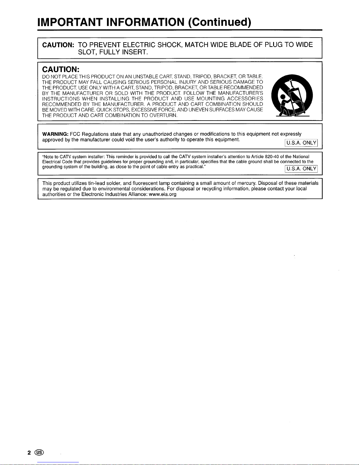
CAUTION: TO PREVENT ELECTRIC SHOCK, MATCH WIDE BLADE OF PLUG TO WIDE
SLOT, FULLY INSERT.
CAUTION:
DO NOT PLACETHIS PRODUCT ON AN UNSTABLE
CART,
STAND, TRIPOD, BRACKET,ORTABLE:
THE PRODUCT MAY FALL CAUSING SERIOUS PERSONAL INJURY AND SERIOUS DAMAGE TO
THE PRODUCT.
USE
ONLY WITH A
CART,
STAND, TRIPOD, BRACKET,ORTABLE RECOMMENDED
BY THE MANUFACTURER OR SOLD WITH THE PRODUCT. FOLLOW THE MANUFACTURER'S
INSTRUCTIONS WHEN INSTALLING THE PRODUCT AND USE
MOUNTING
ACCESSORIES
RECOMMENDED
BY
THE MANUFACTURER. A PRODUCT AND CART COMBINATION SHOULD
BE
MOVED WITH CARE. QUICKSTOPS, EXCESSIVE FORCE, AND UNEVEN SURFACES
MAY
CAUSE
THE PRODUCT AND CART COMBINATION TO OVERTURN.
WARNING: FCC Regulations state that any unauthorized changes
or
modifications to this equipment not expressly
approved by the manufacturer could void the user's authority to operate this equipment.
I U.S.A. ONLYI
"Note to CATV system installer: This reminder is provided to call the CATV system installer's attention to Article 820-40 of the National
Electrical Code that provides guidelines for proper grounding and,
in
particular, specifies that the cable ground shall be connected to the
grounding system of the building, as close to the point of cable entry as practical."
I U.S.A. ONLYI
This product utilizes tin-lead solder, and fluorescent lamp containing a small amount of mercury. Disposal of these materials
may be regulated due to environmental considerations. For disposal or recycling information, please contact your local
authorities or the Electronic IndustriesAlliance: www.eia.org
2@
DEAR SHARP CUSTOMER
Thank you for your purchase of the Sharp Liquid Crystal Television. To ensure safety and many years
of trouble-free operation of your product, please read the Important Safety Precautions carefully before
using this product.
IMPORTANT SAFETY PRECAUTIONS
Electricity is used to perform many useful functions, but it can also cause personal injuries and property damage if
improperly handled. This product has been engineered and manufactured with the highest priority
on
safety. However,
improper use can result
in
electric shock and/or fire.Inorder to prevent potential danger, please observe the following
instructions when installing, operating and cleaning the product.
To
ensure your safety and prolong the service life of your
LCD color TV product, please read the following precautions carefully before using the product.
• Read instructions-All operating instructions must
be
read and understood before the productisoperated.
• Keep this manual
in
a safe
place-These
safety and operating instructions must be keptina safe place for future
reference.
• Observe
warnings-All
warningsonthe product andinthe instructions must be observed closely.
• Follow instructions-All operating instructions must
be
followed.
•
Attachments-Do
not use attachments not recommendedbythe manufacturer. Use of inadequate attachments
can result
in
accidents.
• Power
source-This
product must operateona power source specifiedonthe specification label. If you are not
sure of the type of power supply used
in
your home, consult your dealer or local power company. For units
designed to operate
on
batteries or another power source, refer to the operating instructions.
• Power cord
protection-The
power cords mustberouted properly to prevent people from steppingonthem or
objects from resting
on
them. Check the cords at the plugs and product.
• If the
AC
adapterismisplaced or needs to be replaced, obtain the same type of adapter from a SHARP service
center or your dealer.
•
Overloading-Do
not overloadACoutlets or extension cords.
Overloading can cause fire or electric shock.
• Entering of objects and
liquids-Never
insertanobject into the product through vents or openings. High voltage
flows
in
the product, and insertinganobject can cause electric shock and/or short internal parts. For the same
reason, do not spill water or liquid
on
the product.
•
Servicing-Do
not attempt to service the product yourself. Removing covers can expose
youtohigh voltage and
other dangerous conditions. Request a qualified service person to perform servicing.
•
Repair-If
any of the following conditions occurs, unplug the power cord from theACoutlet, and request a qualified service person to perform repairs.
a.
When the power cord or plugisdamaged.
b.
When a liquid was spilledonthe product or when objects have fallen into the product.
c.
When the product has been exposed to rain or water.
d.
When the product does not operate properly as describedinthe operating instructions.
Do
not touch the controls other than those describedinthe operating instructions. Improper adjustment of
controls not described
in
the instructions can cause damage, which often requires extensive adjustment work
by
a qualified technician.
e.
When the product has been dropped or damaged.
f.
When the product displaysanabnormal condition. Any noticeable abnormalityinthe product indicates that the
product needs servicing.
• Replacement
parts-In
case the product needs replacement parts, make sure that the service person uses
replacement parts specified by the manufacturer, or those with the same characteristics and performance
as
the
original parts. Use of unauthorized parts can result
in
fire, electric shock and/or other danger.
• Safety
checks-Upon
completionofservice or repair work, request the service technician to perform safety checks
to ensure that the product is
in
proper operating condition.
• Wall or ceiling
mounting-When
mounting the productona wall or ceiling, be sure to install the product according
to the method recommended by the manufacturer.
• Polarization-This AC adapter may
be
equipped with a polarized alternating current line plug(aplug having one
blade wider than the other). This plug will fit into the power outlet only one way. This is a safety feature. If you are
unable
to
insert the plug fully into the outlet, try reversing the plug. If the plug should still fail to fit, contact your
electrician to replace your obsolete outlet.
Do
not defeat the safety purpose of the polarized plug.
@3

IMPORTANT SAFETY PRECAUTIONS (Continued)
•
Cleaning-Unplug
the power cord from the AC outlet before cleaning the product.
Use a damp cloth to clean the product.
Do
not use liquid cleaners or aerosol
cleaners.
• Water and
moisture-Do
not use the product near water, suchasbathtub,
washbasin, kitchen sink and laundry tub, swimming pool and
in
a wet basement.
•
Stand-Do
not place the productonan
unstable cart, stand, tripod or table.
Placing the product
onanunstable base can cause the product to fall, resulting
in
serious personal injuries as well as damage to the product. Use only a cart,
stand, tripod, bracket or table recommended
by
the manufacturer or sold with the
product. When mounting the product
on
a wall,besuretofollow the manufacturer's instructions. Use only the mounting hardware recommended by the manufacturer.
• When relocating the product placed
on
a cart, it mustbemoved with utmost care.
Sudden stops, excessive force and uneven floor surface
can
cause the product to
fall from the cart.
•
Ventilation-The
vents and other openingsinthe cabinet are designed for
~
,~
ventilation.Donot cover or block these vents and openings since insufficient
ventilation can cause overheating and/or shorten the life of the product.
Do
not
/1
\-1
place the productona bed, sofa,
rug
or other similar surface, since they can
D
block ventilation openings. This product is not designed for built-in installation; do
#
not place the productinan
enclosed place suchasa bookcase or rack, unless
proper ventilation
is
provided or the manufacturer's instructions are followed.
~
• The Liquid Crystal panel usedinthis productismade of glass. Therefore, it can
break when the product is dropped or applied with impact.
Be
careful not to be
injured
by
broken glass piecesincase the Liquid Crystal panel breaks.
• Heat
sources-Keep
the product away from heat sources such as radiators,
heaters, stoves and other heat-generating products (including amplifiers).
• The Liquid Crystal panel
is
a very high technology product with
921
,600 thin film transistors, giving you fine picture
details.
Occasionally, a few non-active pixels may appear
on
the
screenasa fixed point of blue, green or
red.
Please note that this does not affect the performance of your product.
4
@)
IMPORTANT SAFETY PRECAUTIONS (Continued)
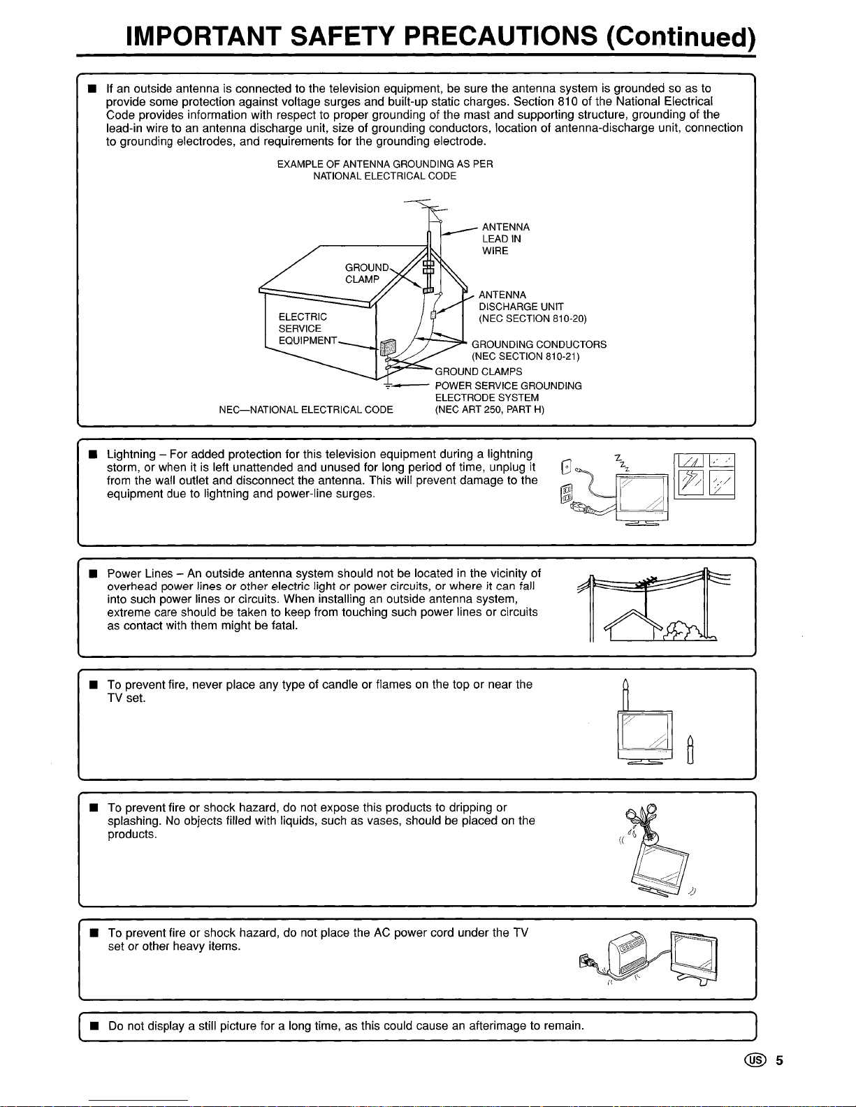
•
If
an
outside antenna is connected to the television equipment, be sure the antenna systemisgrounded soasto
provide some protection against voltage surges and built-up static charges. Section 810 of the National Electrical
Code provides information with respect to proper grounding of the mast and supporting structure, grounding of the
lead-in wire to
an
antenna discharge unit, size of grounding conductors, location of antenna-discharge unit, connection
to grounding electrodes, and requirements for the grounding electrode.
EXAMPLEOFANTENNA GROUNDING AS PER
NATIONAL ELECTRICAL CODE
ANTENNA
LEAD
IN
WIRE
ANTENNA
DISCHARGE UNIT
(NEC SECTION 810-20)
GROUNDING CONDUCTORS
(NEC SECTION 810-21)
GROUND CLAMPS
-:-'-
POWER SERVICE GROUNDING
ELECTRODE SYSTEM
(NEC ART 250, PART
H)
ELECTRIC
SERVICE
EQUIPMENT
NEG-NATIONAL
ELECTRICAL CODE
GROUND
CLAMP
•
Lightning - For added protection for this television equipment during a lightning
7-
lLLl~
storm, or when itisleft unattended and unused for long period of time, unplug it
G 27-
from the wall outlet and disconnect the antenna. This will prevent damage to the
~~q]
[Zj[2
equipment due to lightning and power-line surges.
• Power Lines -
An
outside antenna system should notbelocatedinthe vicinity of
overhead power lines or other electric light or power circuits, or where
it can fall
into such power lines or circuits. When installing
an
outside antenna system,
extreme care should
be
taken to keep from touching such power lines or circuits
as contact with them might
be
fatal.
•
To prevent fire, never place any type of candle or flamesonthe top or near the
~
TV set.
0
~
~
===-==
•
To
prevent fire or shock hazard, do not expose this products to dripping or
splashing.
No
objects filled with liquids, such as vases, shouldbeplacedonthe
products.
•
To
prevent fire or shock hazard, do not place theACpower cord under the TV
set or other heavy items.
•
Do
not display a still picture for a long time,asthis could causeanafterimage to remain.
@5
Contents
IMPORTANT INFORMATION 1
DEAR SHARP CUSTOMER 3
IMPORTANT SAFETY PRECAUTIONS 3
Contents
6
Supplied Accessories 7
Preparation 8
Installing Batteriesinthe Remote Control 8
Using the Remote Control 8
Antenna Connection 9
Power Connection 10
Part Names of Main Unit
11
Listening with Headphones
11
How to Fix the Cables 12
Part NamesofRemote Control
13
TV SignalsinYour Region
13
EZ SETUP (With AUTO CLOCK Setting)
14
EZ
SETUP during the First Power On 14
Setting the CLOCK 15
AUTO CLOCK Setting 15
MANUAL CLOCK Setting 16
TIME DISPLAY 16
Basic Operation
17
Turning On and Off the Main Power 17
Standby 17
SWitching the Input Modes
(INPUT1/INPUT2/INPUT3JTV) 17
Sound Volume 18
Changing Channels 18
Selecting Menu Items 19
Basic Adjustment Settings
21
AV
MODE
21
OPC
21
BACKLIGHT 22
PICTURE Adjustments 22
COLOR TEMPERATURE
..
" 23
AUDIO Adjustments 23
6@
Useful Features 24
CH-SETIING 24
SETUP
25
V-CHIP Settings 26
CLOSED CAPTION
31
VIEW MODE 32
AUDIO ONLY 32
BLUE SCREEN 32
SLEEP TIMER 33
WAKE-UP TIMER 33
NO SIGNAL OFF 34
NO OPERATION OFF
..
" 34
PICTURE FLIP 34
Connecting External Devices 35
Example of External Devices that can be
Connected 35
Outputting Video and Audio (Video Output) 35
Connecting a
VCR,
DVD
Playerora Camcorder
to INPUT1/INPUT2/INPUT3 36
Troubleshooting 37
Specifications 38
Calling for
Service
39
LIMITED WARRANTy 39
Dimensional Drawings
• The dimensional drawings for the LCD TV set are shown on
the inside backcover.
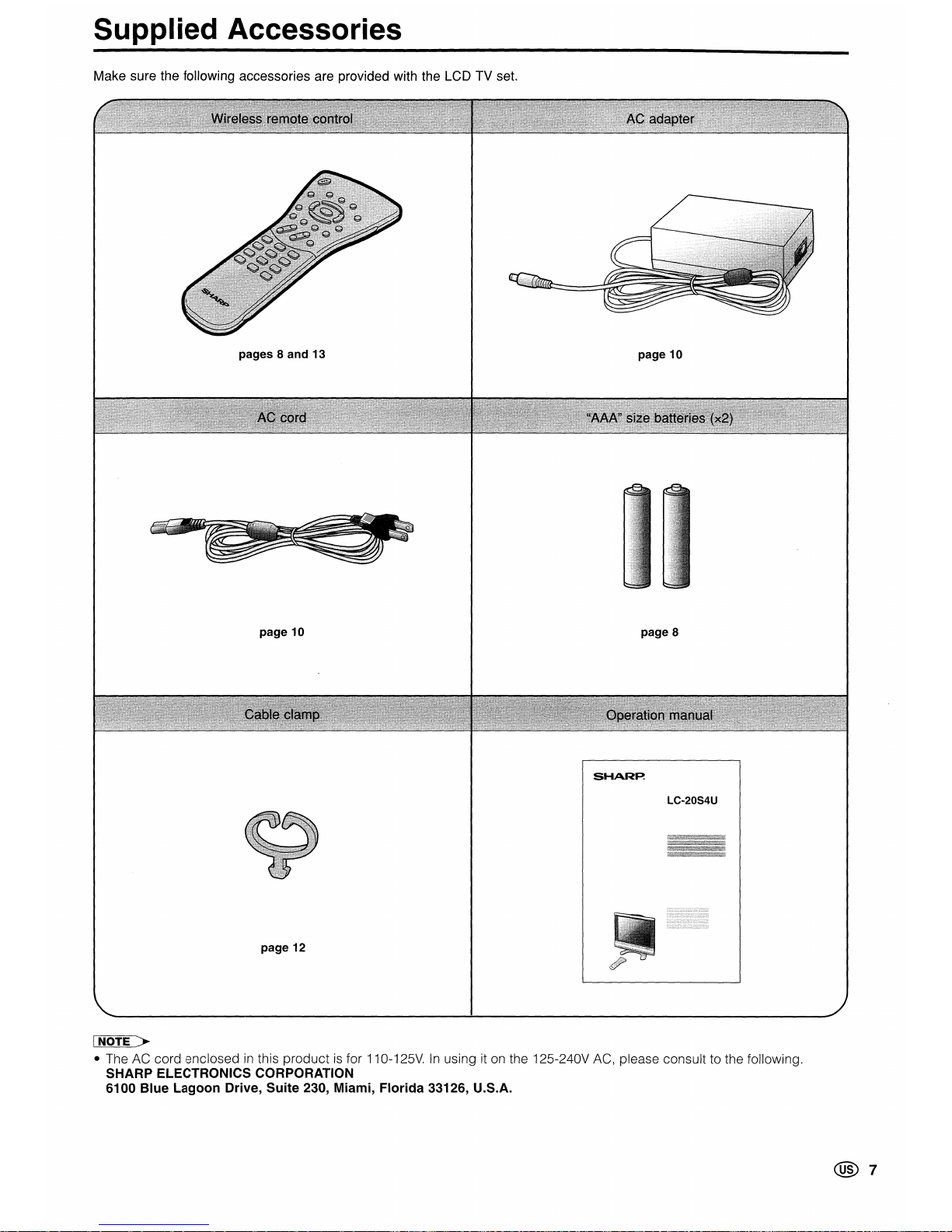
Supplied Accessories
Make sure the following accessories are provided with the LCD TV set.
pages 8 and 13
page 10
page 10
page 8
SHARP:
LC-20S4U
page 12
INOTE >
• The AC cord enclosedinthis productisfor110-125V.Inusing itonthe 125-240V AC, please consult to the following.
SHARP ELECTRONICS CORPORATION
6100
Blue
Lagoon
Drive,
Suite
230, Miami,
Florida
33126, U.S.A.
@7
Preparation
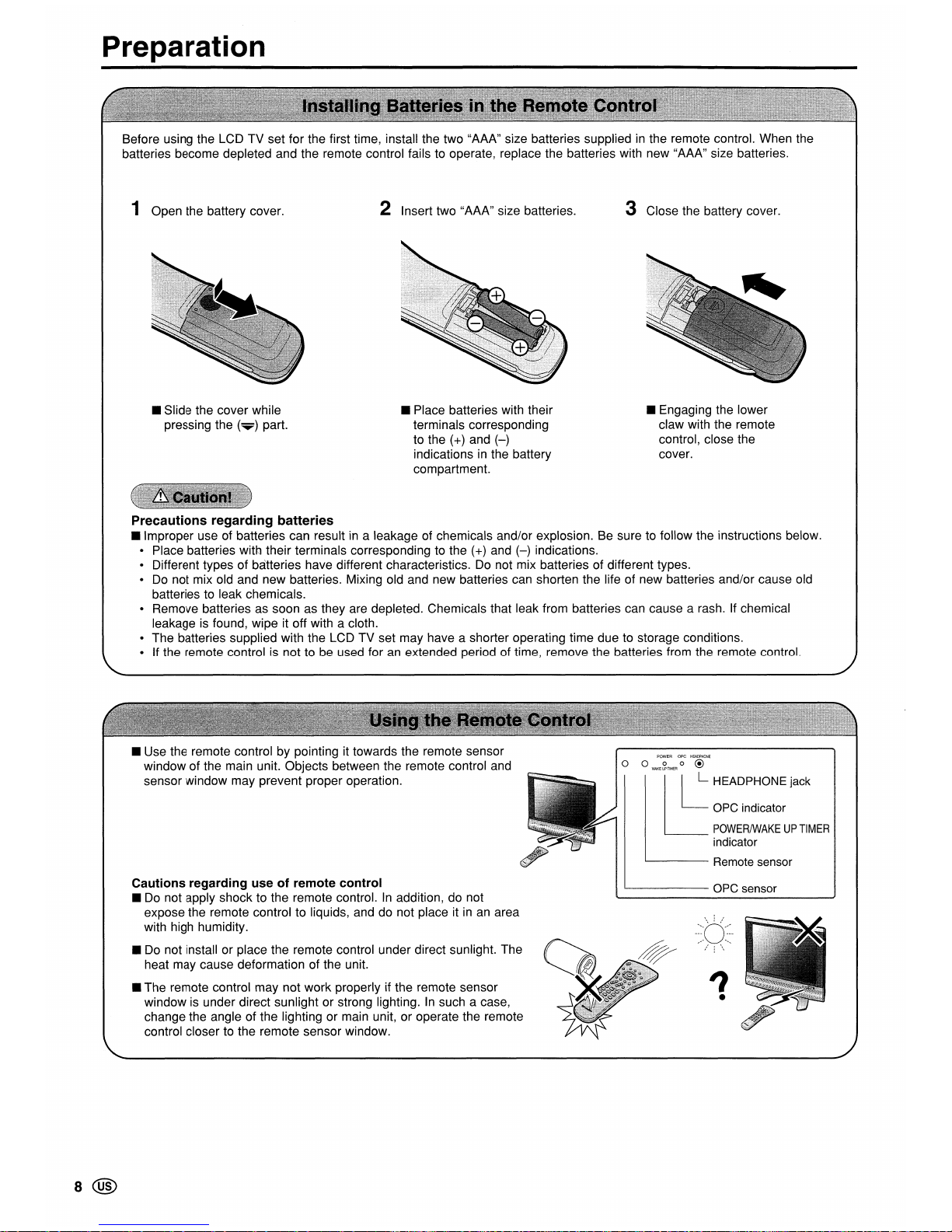
Before using the LCDTVset for the first time, install the two "AAA" size batteries supplied in the remote control. When the
batteries become depleted and the remote control fails to operate, replace the batteries with new "AAA" size batteries.
1 Open the battery cover.
• Slide the cover while
pressing the
(T)
part.
2 Insert two "AAA" size batteries.
• Place batteries with their
terminals corresponding
to the (+) and
(-)
indications in the battery
compartment.
3 Close the battery cover.
• Engaging the lower
claw with the remote
control, close the
cover.
Precautions regarding batteries
• Improper use of batteries can result in a leakage of chemicals and/or explosion. Be sure to follow the instructions below.
Place batteries
wit~
their terminals corresponding to the (+) and
(-)
indications.
Different typesofbatteries have different characteristics. Do not mix batteries of different types.
Do not mix old and
new
batteries. Mixing old and new batteries can shorten the life of new batteries and/or cause old
batteries to leak chemicals.
Remove batteries as soon as they are depleted. Chemicals that leak from batteries can cause a rash. If chemical
leakage is found, wipe it off with a cloth.
The
batteries supplied with the LCDTVset may have a shorter operating time due to storage conditions.
If the remote control is not to be used for an extended period of time, remove the batteries from the remote control.
8@
• Use the remote controlbypointing it towards the remote sensor
window of the main unit. Objects between the remote control and
sensor window may prevent proper operation.
Cautions regarding use of remote control
• Do not apply shock to the remote control.Inaddition, do not
expose the remote control to liquids, and do not place it in an area
with high humidity.
• Do not install or place the remote control under direct sunlight. The
heat may cause deformation of the unit.
• The remote control may not
work
properlyifthe remote sensor
window is under direct sunlightorstrong lighting.Insuch a case,
change the angle of the lighting or main unit, or operate the remote
control closer to the remote sensor window.
POWER ope
HEADPHONE
o 0
WAKE~TIMER
0 @
II
L HEADPHONE jack
OPC indicator
POWERIWAKEUPTIMER
indicator
'--------
Remote sensor
1...--
OPC sensor
?
•
Preparation (Continued)
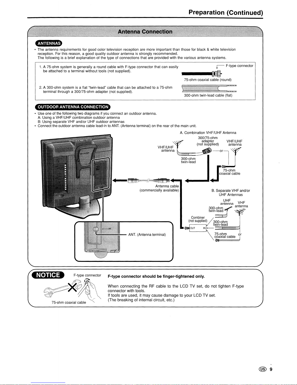
• The antenna requirements for good color television reception are more important than those for black & white television
reception. For this reason, a good quality outdoor antenna is strongly recommended.
The following is a brief explanation of the type of connections that are provided with the various antenna systems.
1. A 75-ohm system is generally a round cable with F-type connector that can easily
be attached to a terminal without tools (not supplied).
~
F-type connector
75-ohm coaxial cable (round)
2. A 300-ohm system is a flat "twin-lead" cable that can be attached to a 75-ohm
terminal through a 300/75-ohm adapter (not supplied).
300-ohm twin-lead cable (flat)
OUTDOOR ANTENNA CONNECTION
• Use one of the following two diagrams if you connect an outdoor antenna.
A: Using a VHF/UHF combination outdoor antenna
B: Using separate VHF and/or
UHF
outdoor antennas
• Connect the outdoor antenna cable lead-in to ANT. (Antenna terminal) on the rear of the main unit.
300-ohm
twin-lead
B.
Separate VH F and/or
UHF Antennas
UHF
antenna VHF
r2i~:?~~
antenna
Combiner
0
(not
supplied)
300-ohm
..,
OUT
1+~W=i=n-~le.a.dllllll~
\~~:~~:ccJ
A.
Combination VHF/UHF Antenna
300/75-ohm
adapter VHF/UHF
(not supplied) antenna
-orr
•
..
Jo~~i~~~ble
VHF/UHF
antenna
Antenna cable
(commercially available)
ANT. (Antenna terminal)
tII!IiI!IEt F-type connector
~l~
~~~
~
75-ohm coaxial cable
F-type connector should be finger-tightened only.
When connecting theRFcable to the LCD TV set, do not tighten F-type
connector with tools.
If
tools are used, it may cause damage to your LCD TV set.
(The breaking of internal circuit, etc.)
@9
Preparation (Continued)
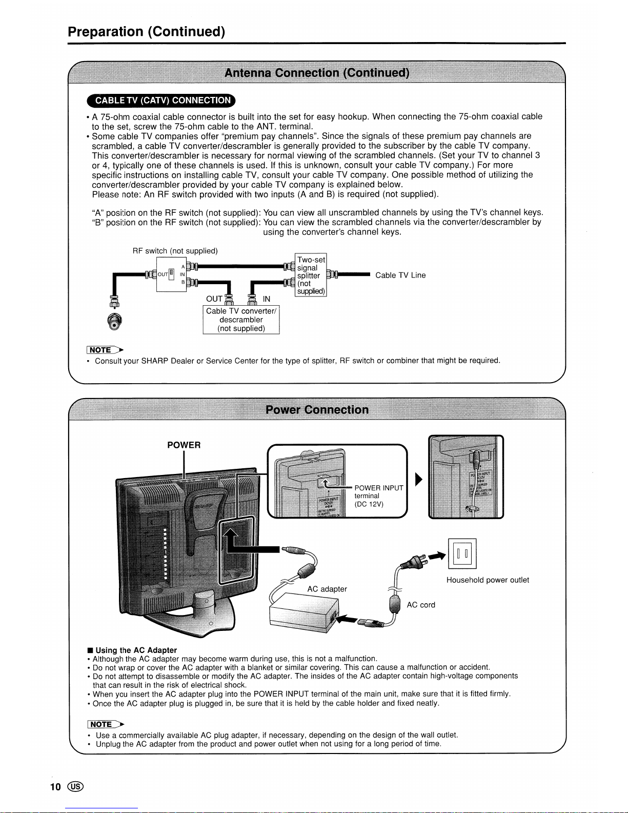
CABLE
TV (CATV) CONNECTION
• A 75-ohm coaxial cable connector is built into the set for easy hookup. When connecting the 75-ohm coaxial cable
to the set, screw the 75-ohm cable to the ANT. terminal.
• Some cable TV companies offer "premium pay channels". Since the signals of these premium pay channels are
scrambled, a cable TV converter/descrambler is generally provided to the subscriber by the cable TV company.
This converter/descrambler is necessary for normal viewing of the scrambled channels. (Set your TV to channel 3
or
4,
typically one of these channels is used.
'If
this is unknown, consult your cable TV company.) For more
specific instructions on installing cable TV, consult your cable TV company. One possible method of utilizing the
converter/descrambler provided by your cable TV company
is
explained below.
Please note:
AnRFswitch provided with two inputs (A andB)is required (not supplied).
"A" position
on
theRFswitch (not supplied):
You
can view all unscrambled channels by using the TV's channel keys.
"B" position
on
theRFswitch (not supplied):
You
can view the scrambled channels via the converter/descrambler by
using the converter's channel keys.
RF
switch (not supplied)
Two-set
A.II_------_IIIJ
signal
IN
splitter
B (not
L..--_----l
supplied)
IN
Cable TV converter/
descrambler
(not supplied)
Cable TV Line
~
• Consult your SHARP Dealer or Service Center for the type of splitter,RFswitch or combiner that mightberequired.
POWER INPUT
terminal
(DC 12V)
Household power outlet
• Using
the
AC Adapter
• Although theACadapter may become warm during use, thisisnot a malfunction.
•
Do
not wrap or cover the AC adapter with a blanket or similar covering. This can cause a malfunction or accident.
•
Do
not attempt to disassemble or modify theACadapter. The insides of the AC adapter contain high-voltage components
that can result
in
the risk of electrical shock.
• When you insert the AC adapter plug into the POWER INPUT terminal of the main unit, make sure that itisfitted firmly.
• Once the
AC
adapter plugisplugged
in,
be sure that itisheld by the cable holder and fixed neatly.
I NOTE >
• Use a commercially availableACplug adapter, if necessary, dependingonthe design of the wall outlet.
• Unplug the
AC
adapter from the product and power outlet when not using for a long period of time.
10
@
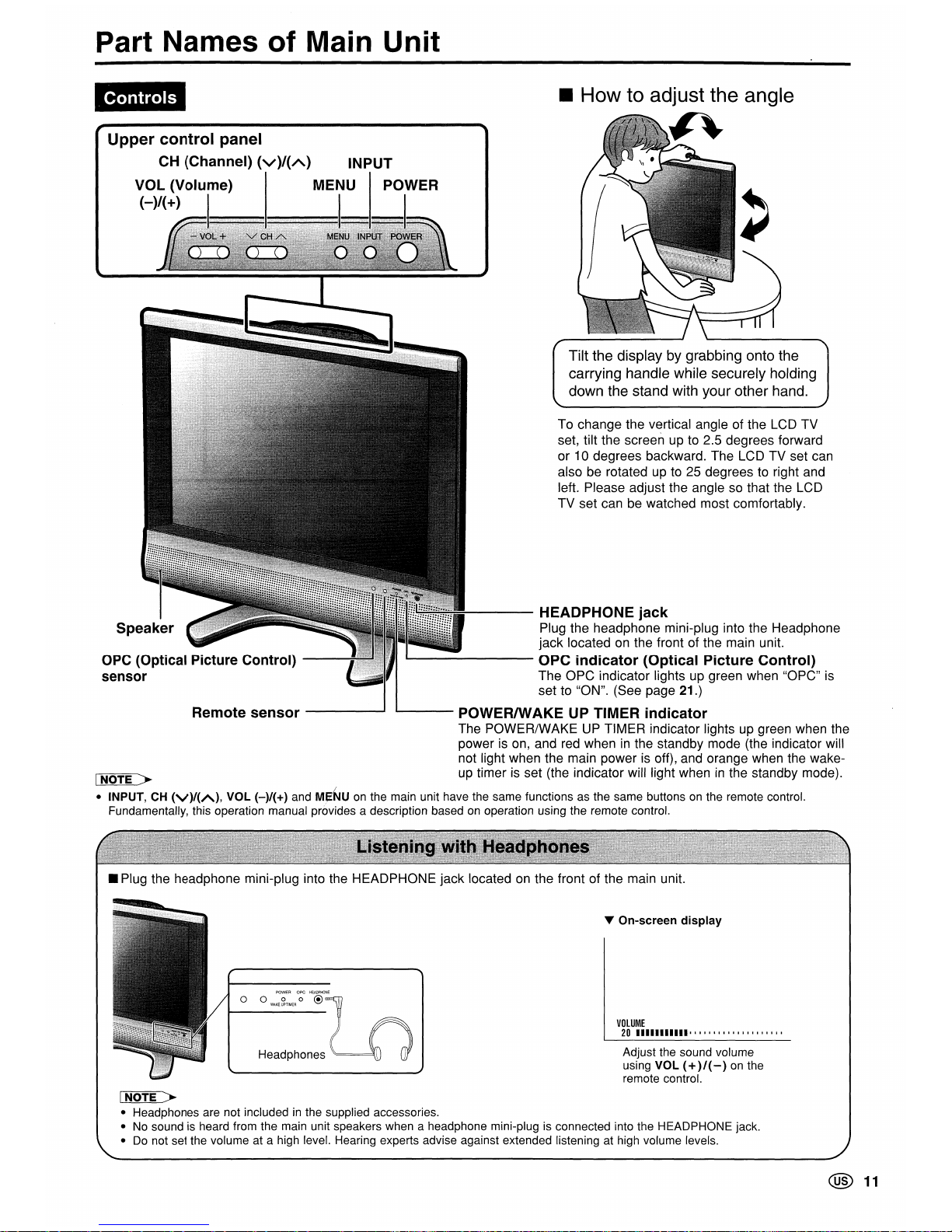
Part Names
of
Main
Unit
Tilt the display by grabbing onto the
carrying handle while securely holding
down the stand with your other hand.
To change the vertical angle of the LCD TV
set, tilt the screen up to 2.5 degrees forward
or
10
degrees backward. The LCD TV set can
also
be
rotated upto25
degreestoright and
left. Please adjust the angle
so
that the LCD
TV set can be watched most comfortably.
Remote
sensor
----
......
Upper
control
panel
CH
(Channel)
(V)/{A)
INPUT
VOL (Volume) MENU POWER
(-)/{+)
Controls
OPC
(Optical Picture Control)
sensor
~---
HEADPHONE
jack
Plug the headphone mini-plug into the Headphone
jack located
on
the front of the main unit.
OPC
indicator
(Optical
Picture
Control)
The OPC indicator lights up green when "OPC"
is
set to "ON". (See page 21.)
1..--
__
POWERIWAKE UP TIMER
indicator
The POWER/WAKEUPTIMER indicator lightsupgreen when the
power
is
on,
and
red
wheninthe standby mode (the indicator will
not light when the main power
is
off), and orange when the wake-
I
NOTE>
up
timerisset (the indicator will light wheninthe standby mode).
• INPUT,CH(V)/(A),
VOL (-)/(+) and MJiNUonthe main unit have the same functions as the same buttonsonthe remote control.
Fundamentally, this operation manual provides a description based
on
operation using the remote control.
• Plug the headphone mini-plug into the HEADPHONE jack locatedonthe front of the main unit.
Headphones
..
On-screen
display
VOLUME
20
•••••••••••
' I I , , , I I I , I I , , , I , I I ,
Adjust the sound volume
using VOL
(+
)/(
-)
on
the
remote control.
!NOTE>
• Headphones are not includedinthe supplied accessories.
•Nosound is heard from the main unit speakers when a headphone mini-plugisconnected into the HEADPHONE jack.
•
Do
not set the volume at a high level. Hearing experts advise against extended listening at high volume levels.
@
11
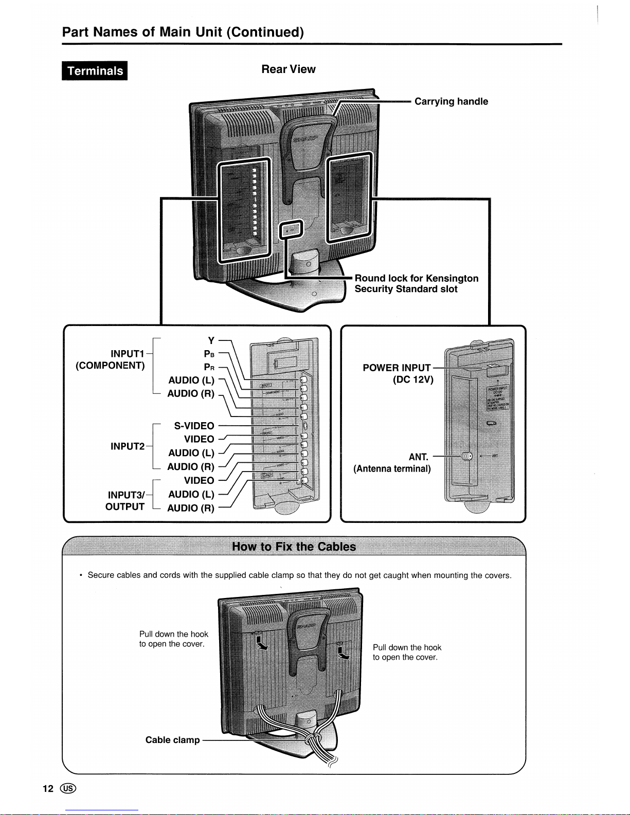
Part Names of Main Unit (Continued)
{
S-VIDEO
VIDEO
INPUT2 AUDIO (L)
AUDIO (R)
{
VIDEO
INPUT31 AUDIO (L)
OUTPUT AUDIO (R)
Terminals
INPUT1
(COMPONENT)
y
PB
PR
AUDIO (L)
AUDIO (R)
Rear View
---
Carrying handle
Round lock for Kensington
Security Standard slot
POWER INPUT
(DC 12V)
ANT.
(Antenna
terminal)
• Secure cables and cords with the supplied cable clamp so that they do not get caught when mounting the covers.
12 @
Pull
down the hook
to
open the cover.
Cable clamp
---......;
Pull
down the hook
to
open the cover.
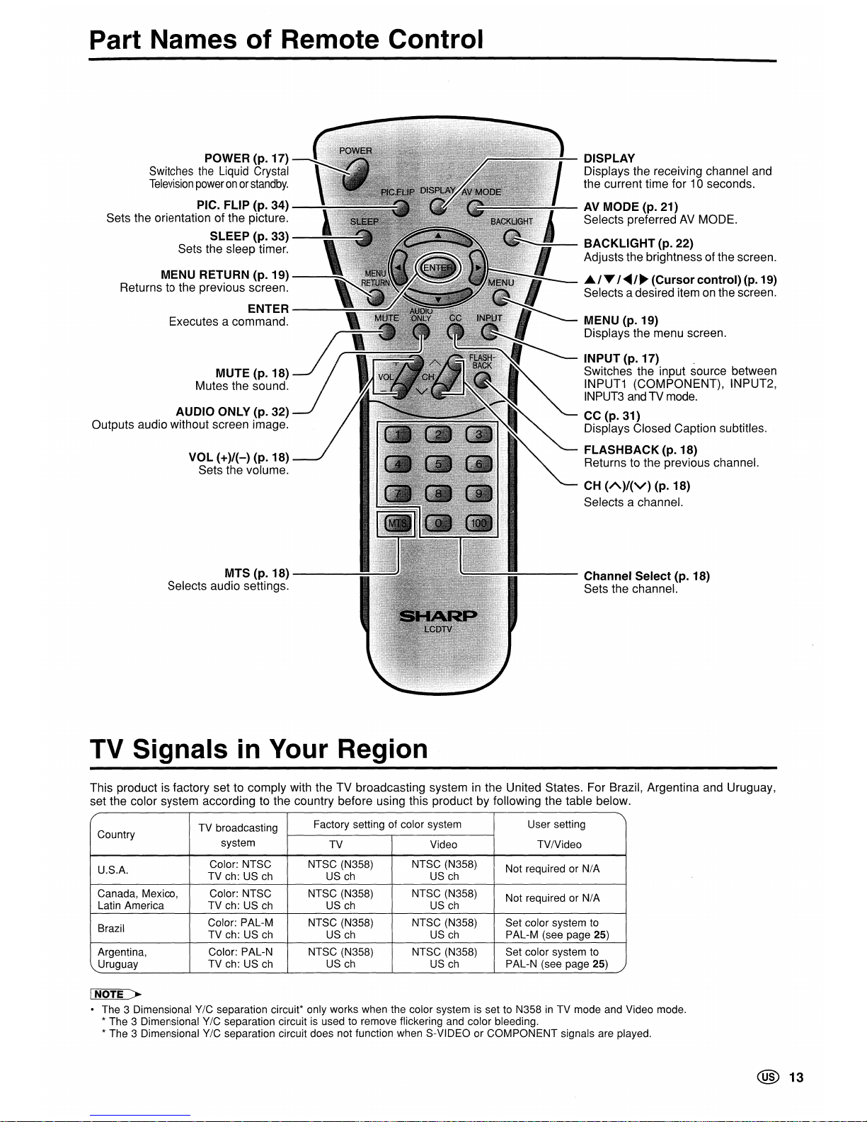
Part Names
of
Remote Control
POWER (p. 17)
Switches
the
Liquid
Crystal
Television
poweronor
standby.
PIC. FLIP (p. 34)
Sets the orientation of the picture.
SLEEP (p. 33)
Sets the sleep timer.
MENU RETURN (p. 19)
--
......
Returns to the previous screen.
ENTER---
Executes a command.
MUTE (p. 18)
Mutes the sound.
AUDIO ONLY (p. 32)
Outputs audio without screen image.
VOL
(+)/(-) (p. 18)
Sets the volume.
MTS(p.18)--...--...--...~~
Selects audio settings.
TV Signals
in
Your Region
DISPLAY
Displays the receiving channel and
the current time for 10 seconds.
AV MODE (p. 21)
Selects preferredAVMODE.
BACKLIGHT
(p. 22)
Adjusts the brightness of the screen.
~/...,
/~/~
(Cursor
control)
(p. 19)
Selects a desired itemonthe screen.
MENU (p. 19)
Displays the menu screen.
INPUT (p. 17) .
Switches the input source between
INPUT1 (COMPONENT), INPUT2,
INPUT3
and
TV mode.
CC (p. 31)
Displays Closed Caption subtitles.
FLASHBACK
(p. 18)
Returns to the previous channel.
CH
(A)/(V)
(p. 18)
Selects a channel.
Channel
Select
(p. 18)
Sets the channel.
This product is factory set to comply with the TV broadcasting system
in
the United States. For Brazil, Argentina and Uruguay,
set the color system according to the country before using this product by following the table below.
Country
TV broadcasting
Factory setting of color system
User setting
system
TV Video TVIVideo
U.S.A.
Color: NTSC NTSC (N358) NTSC (N358)
Not required or
N/A
TV ch: US
ch
US
ch
US
ch
Canada, Mexico, Color: NTSC NTSC (N358) NTSC (N358)
Not required or
NI
A
Latin America TV ch: US
ch
US
ch
US
ch
Brazil
Color: PAL-M
NTSC (N358) NTSC (N358) Set color system to
TV ch: US
ch
US
ch
US
ch
PAL-M(see page 25)
Argentina,
Color: PAL-N NTSC (N358) NTSC (N358) Set color system to
Uruguay
TV ch: US
ch
US
ch
US
ch
PAL-N (see page 25)
INOTE >
• The 3 Dimensional Y/C separation circuit* only works when the color system is set to N358inTV mode and Video mode.
* The 3 Dimensional
Y/C separation circuit
is
used to remove flickering and color bleeding.
* The 3 Dimensional
Y/C separation circuit does not function when S-VIDEO or COMPONENT signals are played.
@
13
 Loading...