

Page 1
SHAR~
AQuas
LC-46E77UN
LC-52E77UN
LIQUID CRYSTAL TELEVISION
TELI~VISEUR
TELEVISOR CON PANTALLA
DE CRISTAL LiQUIDO
OPERATION
MODE
MANUAL
D'EMPLOI
ACL
MANUAL
DE
OPERACJ6!N
';{'
li@iiiJWJi"';t
•
NOM
1245
IIlDOLB'l
HIGH-OEFINITION
TELEVISION
IMPORTANT : Please read this operation manual before starting operating the equipment.
IMPORTANT : Veuillez lire ce mode d'emploi avant de commencer
IMPORTANTE : Lea este manual de operaci6n antes de comenzar a operar
DIGITAL
I
HIGH-DEFINITION
MULTIMEDIA
it utiliser I'appareil.
INTERFAce
el
equipo.
Page 2
IMPORTANT:
To aid reporting
TV's model and serial numbers
numbers are located
in
case of loss or theft, please record the
at
the rear of the
LC-46E77UN
LC-52E77UN
LIQUID CRYSTAL TELEVISION
ENGLISH
OPERATION MANUAL
I
Mod~
in
the space provided. The
TV.
No
Senal No.:
IMPORTANT INFORMATION
WARNING: TO REDUCE THE RISK OF FIRE OR ELECTRIC SHOCK, DO
NOT EXPOSE THIS PRODUCT TO RAIN OR MOISTURE.
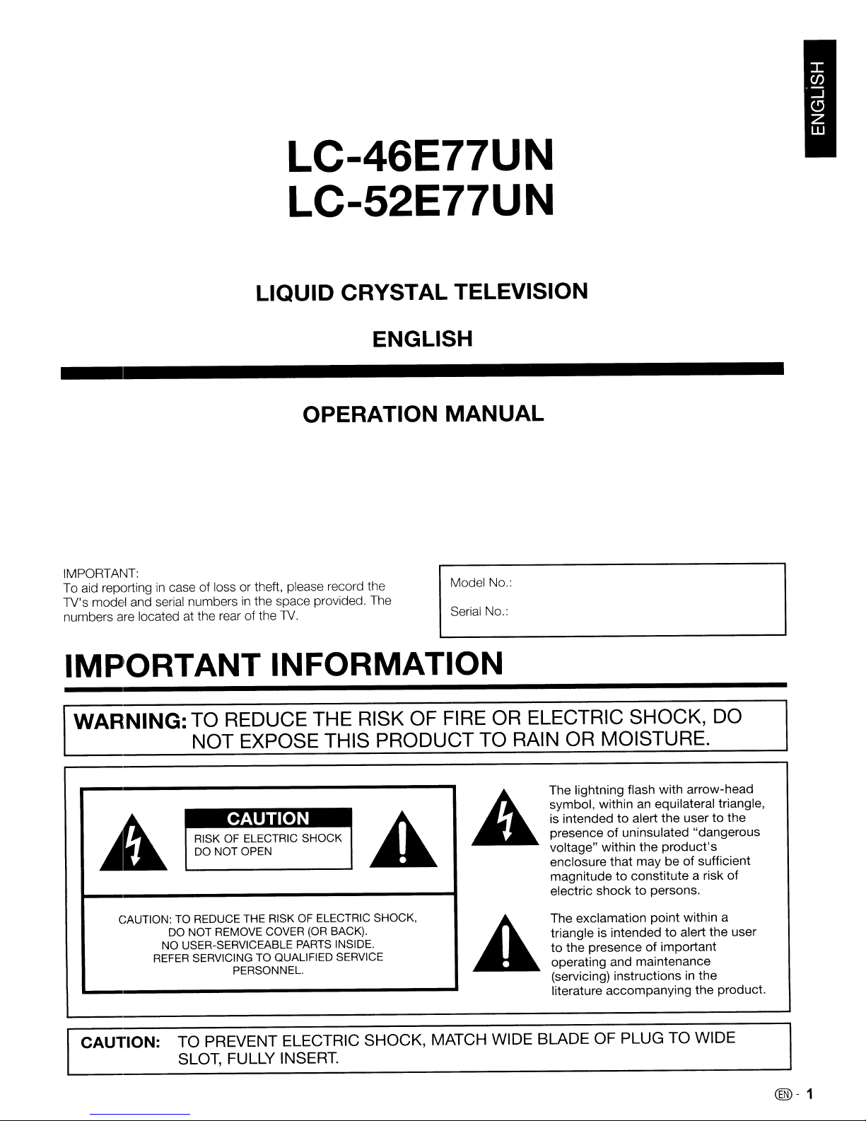
The lightning flash with arrow-head
CAUTION
RISK OF ELECTRIC
DO NOT OPEN
CAUTION: TO REDUCE THE RISK OF ELECTRIC SHOCK,
DO NOT REMOVE COVER
NO
USER-SERVICEABLE PARTS INSIDE.
REFER SERVICING TO QUALIFIED SERVICE
PERSONNEL.
CAUTION: TO PREVENT ELECTRIC SHOCK, MATCH WIDE BLADE OF PLUG TO WIDE
SLOT,
FULLY INSERT.
SHOCK
(OR
BACK).
symbol, within an equilateral triangle,
to
alert
the
is intended
of
presence
voltage" within the
enclosure that may beofsufficient
magnitude
electric shock
The exclamation point within a
triangle is intended
to the presence of important
operating and maintenance
(servicing) instructions
literature accompanying the product.
uninsulated "dangerous
to
constitute a risk of
to
usertothe
product's
persons.
to
alert the user
in
the
@-1
Page 3
IMPORTANT INFORMATION
WARNING:
approvedbythe
FCC Regulations state that any unauthorized changes or modificationstothis
manufacturer could void the user's authoritytooperate this equipment.
equipment
not
expressly
CAUTION:
This
product
equipment.Toprevent electromagnetic interference with electric appliances such as radios and televisions, use shielded
cables and connectors
satisfies FCC regulations when shielded cables and connectors are usedtoconnect
for
connections.
the unittoother
DECLARATION OF CONFORMITY:
SHARP LIQUID CRYSTAL TELEVISION, MODEL LC-46E77UN/LC-52E77UN
This device complies with Part 15ofthe FCC Rules. Operation is subjecttothe following
(1)
This device may
not
cause harmful interference, and
(2)
this device must
accept
two
conditions:
any interference
received, including interference that may cause undesired operation.
RESPONSIBLE
For Business Customers: URL
PARTY:
SHARP ELECTRONICS CORPORATION
Sharp Plaza, Mahwah,
TEL: 1-800-BE-SHARP
New
Jersey 07495-1163
http://www.sharpusa.com
INFORMATION:
This equipment
Rules. These limits
equipment generates, uses
instructions, may cause harmful interference to radio communications. However, there is
in
occur
determined by turning the equipment off and on, the user is encouraged to try to correct the interference by one or more of the
following measures:
- Reorient or relocate the receiving antenna.
- Increase the separation between the equipment and receiver.
- Connect the equipment into
- Consult the dealer or
has
been tested and found to comply with the limits for a Class B digital device, pursuant to Part15of the
are
designed to provide reasonable protection against harmful interferenceina residential installation. This
and
can radiate radio frequency energy and, if not installed and usedinaccordance with the
a particular installation.Ifthis equipment does cause harmful interference to radio or television reception, which can
an
an
outletona circuit different from that to which the receiverisconnected.
experienced radiofTV technician for help.
no
guarantee that interference will not
FCC
be
"NotetoCATV
Electrical
grounding
system
Code
systemofthe
installer:
that provides guidelines for proper grounding
This
reminderisprovidedtocall
building,asclosetothe
pointofcable
the
CATV
and,inparticular,
entryaspractical."
system
installer's attentiontoArticle 820-40ofthe
specifies that
the
cable
ground
shallbeconnectedtothe
National
This product utilizes tin-lead solder, and fluorescent lamp containing a small amount of
mercury. Disposal of these materials may be regulated duetoenvironmental
considerations. For disposal or recycling information, please contact your local
authorities, the Electronic Industries Alliance: www.eiae.org, the lamp recycling
organization: www.lamprecycle.org or Sharp at 1-800-BE-SHARP
(For U.S.A. only)
Trademarks
•
Manufactured
Laboratories.
• "HDMI,
Licensing LLC."
•
Products
efficiency.
• L C
7;t
This
productisembedded
displaying
under
the
HDMIIogo
that
have earned
"/
r-,
L C F 0
easy-to-read
license
from
Dolby
Laboratories.
and High-Definition
the
ENERGY STAR® are designedtoprotect
NT,
I)I;Y-7;t
with LC Font technology,
characters on LCD screens. However,
Multimedia
"/
r-
and LC
which
"Dolby"
Interface are
and
logo
mark are registered trademarksofSHARP Corporation.
was
developedbySHARP
other
the
double-D
trademarksorregistered
the
fonts
symbol
environment
are used
are
Corporation
for
some
trademarksofDolby
trademarksofHDMI
through
superior
for
clearly
screen pages, too.
energy
@-2
Page 4
DEAR SHARP
CUSTOMER
Thank you for your purchaseofthe Sharp Liquid Crystal Television. To ensure safety and many years
of trouble··free operation of your product, please read the Important Safety Instructions carefully before
using this product.
IMPORTANT SAFETY INSTRUCTIONS
Electricity is usedtoperform many useful functions, but it can also cause personal injuries and property damage
on
if improperly handled. This product has been engineered and manufactured with the highest priority
in
However, improper use can result
observe the following instructions when installing, operating and cleaning the product.
and prolong the service life
before using the product.
1)
Read these instructions.
2)
Keep these instructions.
3)
Heed all warnings.
4)
Follow all instructions.
5)
Do not use this apparatus near water.
6)
Clean only with dry cloth.
7)
Do not
8)
Do not install near any heat sources such as radiators, heat registers, stoves, or other apparatus (including
amplifiers) that produce heat.
9)
Do not defeat the safety purposeofthe polarized or grounding-type plug. A polarized plug has
with one wider than the other. A grounding type plug has
wide blade or the third prong are provided for your safety. If the provided plug does not fit into your outlet,
consult
10) Protect the power cord from being walked on or pinched particularly at plugs, convenience receptacles,
and the point where they exit from the apparatus.
11) Only use attachments/accessories specified
12) Use only with the cart, stand, tripod, bracket, or table specified by the manufacturer, or sold
with the apparatus. When a cart is used, use caution when moving the cart/apparatus
combination
13) Unplug this apparatus during lightning storms or when unused for long periods
14) Refer all servicing
damaged
have fallen into the apparatus, the apparatus has been exposed
normally, or has been dropped. .
block
any ventilation openings. Installinaccordance with the manufacturer's instructions.
an
electrician for replacementofthe obsolete outlet.
to
in
any way, such as power-supply cord or plug is damaged, liquid has been spilled or objects
of
avoid injury from tip-over.
to
qualified service personnel. SerVicing is required when the apparatus has been
electric shock and/or fire.Inordertoprevent potential danger, please
To
ensure your safety
your Liquid Crystal Television, please read the following precautions carefully
two
blades and a third grounding prong. The
by
the manufacturer.
of
time.
to
rain or moisture, does not operate
safety.
two
fi)
blades
Additional Safety Information
15) Power
16) Overloading- Do not overload wall outlets, extension cords, or integral convenience receptacles as this
17) Object and Liquid Entry- Never push objects
18) Damage Requiring
19) Replacement
20)
21) Wall or ceiling
Sourcesmarking label. If you are not sure
local power company. For products intended to operate from battery power, or other sources, refer
operating instructions.
can result
touch dangerous voltage points or short-out parts that could result
of
liquid
service personnel under the following conditions:
replacement parts specified
Unauthorized substitutions may result
Safety
perform safety checkstodetermine that the product isinproper operating condition.
according
any kind on the product.
a)
When the AC cord or plug is damaged,
b)
If liquid has been spilled, or objects have fallen into the product,
c)
If the product has been exposedtorain or water,
d)
If the product does not operate normally by following the operating instructions.
Adjust only those controls that are covered by the operating instructions as
of
other controls may resultindamage and will often require extensive work by a qualified technician
to
restore the product to its normal operation,
e)
If the product has been dropped or damagedinany way, and
f)
When the product exhibits a distinct changeinperformance - this indicates a need for service.
Check-Upon
This product should be operated only from the typeofpower source indicated on the
of
the typeofpower supply to your home, consult your product dealer or
in
a riskoffire or electric shock.
of
any kind into this product through openings as they may
in
a fire or electric shock. Never spill
Service-Unplug
Parts-When
mounting-When
to
the method recommendedbythe manufacturer.
replacement parts are required, be sure the service technician has used
by
completionofany service or repairstothis product, ask the service technician
this product from the wall outlet and refer servicing to qualified
an
improper adjustment
the manufacturer or have the same characteristics as the original part.
in
fire, electric shock, or other hazards.
mounting the product on a wall or ceiling, be suretoinstall the product
to
to
the
@-3
Page 5
IMPORTANT SAFETY INSTRUCTIONS
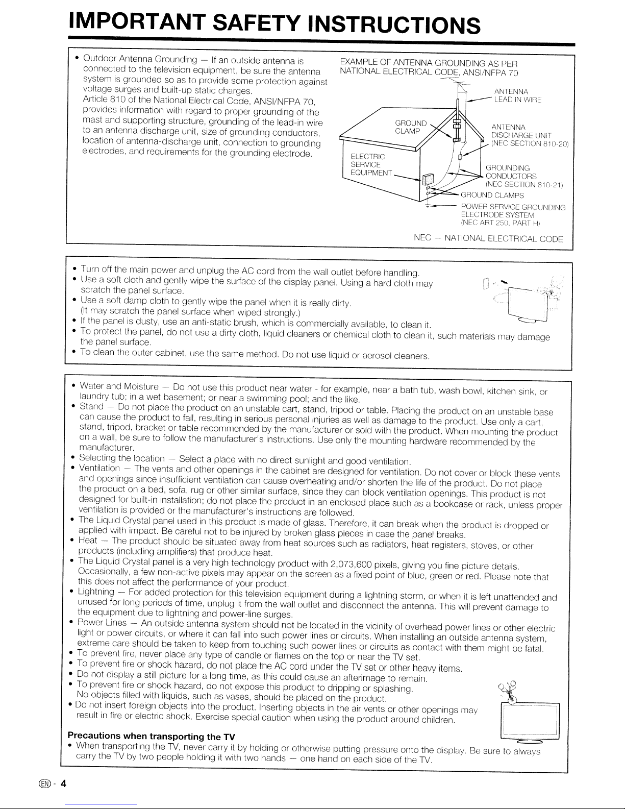
• Outdoor Antenna Grounding -Ifan
connected to the television equipment, be sure the antenna
is
system
voltage surges and built-up static charges.
Article 810 of the National Electrical Code, ANSI/NFPA 70,
provides information with regard to proper grounding of the
mast and supporting structure, grounding of the lead-in wire
to
location of antenna-discharge unit, connection to grounding
electrodes, and requirements for the grounding electrode.
• Turn off tile main power and unplug the AC cord from the wall outlet before handling.
• Use a soft cloth and gently wipe the surface of the display panel. Using a hard cloth may
scratch the panel surface.
• Use a soft damp cloth to gently wipe the panel when
(It
•
If
the panelisdusty, useananti-static brush, whichiscommercially available, to clean
• To protect the panel,donot use a dirty cloth, liquid cleaners or chemical cloth to clean it, such materials may damage
the panel suriace.
• To clean the outer cabinet, use the same method. Do not use liquid or aerosol cleaners.
grounded so as to provide some protection against
an
antenna discharge unit, size of grounding conductors,
may scratch the panel surface when wiped strongly.)
outside antenna
is
itisreally dirty.
EXAMPLE OF ANTENNA GROUNDING AS PER
NATIONAL ELECTRICAL CODE, ANSI/NFPA
,.-------.,jl
ELECTRIC
SERVICE
EQUIPMENT
~
I-f--':::::::"L
~,..c:::-.
~-
NEC - NATIONAL ELECTRICAL CODE
it.
GROUND CLAMPS
POWER SERVICE GROUNDING
ELECTRODE SYSTEM
(NEC ART
j----
GROUNDING
CONDUCTORS
(NEC SECTION
ANTENNA
LEADINWIRE
ANTENNA
DISCHARGE UNIT
(NEC SECTION
250.
70
PAm
81021)
H)
810-201
• Water and Moisture - Do not use this product near water - for example, near a bath tub, wash bowl, kitchen sink, or
in
laundry tub;
• Stand - Do not place the product on
can cause the product to
stand, tripod, bracket or table recommended by the manufacturer or sold with the product. When mounting the product
on a wall, be sure to follow the manufacturer's instructions. Use only the mounting hardware recommended by the
manufacturer.
• Selecting the location - Select a place with no direct sunlight and good ventilation.
• Ventilation - The vents and other openings
and openings since insufficient ventilation can cause overheating and/or shorten the life of the product. Do not place
the product on a bed, sofa, rug or other similar suriace, since they can block ventilation openings. This productisnot
designed for built-in installation; do not place the product
ventilation
• The Liquid Crystal panel used
applied with impact. Be careful not to be injured by broken glass pieces
• Heat - The product should be situated away from heat sources such as radiators, heat registers, stoves, or other
products (including amplifiers) that produce heat.
• The Liquid Crystal panel
Occasionally, a few non-active pixels may appear
this does not affect the periormance of your product.
• Lightning
unused for long periods of time, unplug
the equipment due to lightning and power-line surges.
• Power Lines light or power circuits, or where
extreme care should be taken to keep from touching such power lines or circuits as contact with them might be fatal.
• To prevent
• To prevent fire or shock hazard, do not place the AC cord under the
• Do not display a still picture for a long time,
• To prevent fire or shock hazard, do not expose this product to dripping or splashing.
No objects filled with liquids, such
• Do not insert foreign objects into the product. Inserting objects
Precautions
• When transporting the
in
result
carry the
a wet basement; or near a swimming pool; and the like.
an
fall,
resultinginserious personal injuriesaswellasdamage to the product. Use only a cart,
is
provided or the manufacturer's instructions are followed.
in
this productismade of glass. Therefore,itcan break when the productisdropped or
is
a very high technology product with 2,073,600 pixels, giving you fine picture details.
~
For added protection for this television equipment during a lightning storm, or whenitis
An
outside antenna system should not be locatedinthe vicinity of overhead power lines or other electric
it
fire,
never place any type of candle or flames on the top or near theTVset.
fire
or electric shock. Exercise special caution when using the product around children.
when
transporting the
TV,
TV
by two people holdingitwith two hands - one hand on each side of the
never carryitby holding or otherwise putting pressure onto the display. Be sure to always
unstable cart, stand, tripod or table. Placing the product onanunstable base
in
the cabinet are designed for ventilation. Do not cover or block these vents
inanenclosed place such as a bookcase or rack, unless proper
in
case tile panel breaks.
on
the screenasa fixed point of blue, green or red. Please note that
it
from the wall outlet and disconnect the antenna. This will prevent damage to
can
fall
into such power lines or circuits. When installinganoutside antenna system,
TV
set or other heavy items.
as
this could causeanafterimage to remain.
as
vases, should be placed on the product.
in
the
air
vents or other openings may
TV
TV.
left unattended and
C:~J
@-4
Page 6

IMPORTANT SAFETY INSTRUCTIONS
CHILD SAFETY:
It
MaKes
Congratulations on your purchase! As you enjoy your new product, please keep these safety tipsinmind:
A Difference How
THE ISSUE
• The home theater entertainment experienceisa growing trend and larger flat panel
displays are popular purchases. However, flat panel displays are not always supported
on the proper stands or installed according to the manufacturer's recommendations.
• Flat panel displays that are inappropriately situated on dressers, bookcases, shelves,
desks, speakers, chests or carts may
THIS MANUFACTURER CARES!
• The consumer electronics industryiscommitted to making home entertainment enjoyable
and safe.
and
Where
You
Use
Your
fall
over and cause injury.
Flat
Panel
Display
TUNE
• One size does NOT
• Carefully read and understand
• Don't allow children to climb on or play with furniture and television sets.
• Don't place flat panel displays on furniture that can easily be used
• Remember that children can become excited while watching a program, especially
• Care should be taken to route
WALL MOUNTING: IF YOU DECIDETOWALL
PANEL DISPLAY, ALWAYS:
• Use a mount that has been recommended by the display manufacturer and/or listed
• Follow
•
• Make sure that the wall where you are mounting the display
• A minimum of two people are required for installation. Flat panel displays can be
www.CE.org/safety
INTO SAFETY
fit
all.
installaticn and use of your flat panel display.
a chest of drawers.
on a "larger than life" flat panel display. Care should be taken to place or install the
display where
display so that they cannot be pulled or grabbed by curious children.
by
an
independent laboratory (suchasUL,
If
you have any doubts about your ability to safely install your flat panel display,
contact your retailer about professional installation.
wall mounts are not designed to be mounted to walls with steel studs or old cinder
block construction.
heavy.
it
cannot be pushed, pulled over, or knocked down.
all
instructions supplied by the display and wall mount manufacturers.
<I~~
Follow the manufacturer's recommendations for the safe
all
enclosed instructions for proper use of this product.
as
all
cords and cables connected to the flat panel
MOUNT
CSA,
ETL).
If
you are unsure, contact a professional installer.
Note: CEA
consumer electronics industry. More than 2,200 companies enjoy the benefits of CEA
membership, including legislative advocacy, market research, technical training and education,
industry promotion and the fostering of business and strategic relationships.
is
the preeminent trade association promoting growthinthe
YOUR FLAT
is
appropriate. Some
steps, such
as
$161
billion U.S.
@-5
Page 7
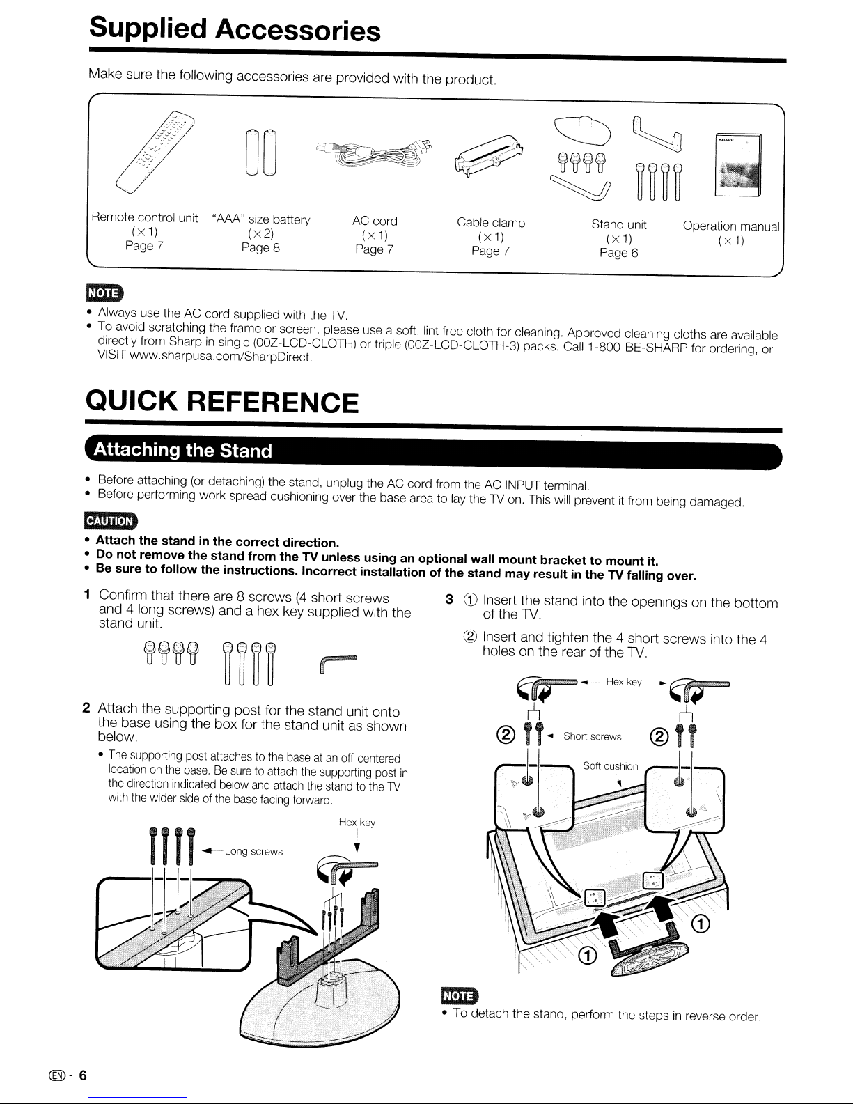
Supplied Accessories
Make sure the following accessories are provided with the product.
Remote control unit
(x
1)
Page 7
"AAA" size battery
(x2)
Page 8
AC cord
(x
1)
Page 7
Cable clamp
(x
1)
Page 7
Stand unit
(x
1)
Page 6
Operation manual
1m
• Always use theACcord
To
avoid scratching the frameorscreen, please use a soft, lint free cloth for cleaning. Approved cleaning cloths are available
•
directly from Sharp
VISIT www.sharpusa.com/SharpDirect.
QUICK
REFERENCE
Attaching the Stand
• Before attaching (or detaching) the stand, unplug the AC cord from the AC INPUT terminal.
• Before performing work spread cushioning over the base area
supplied with the 1V.
in
single
(OOZ
-LCD-CLOTH)ortriple
(OOZ
-LCD-CLOTH-3) packs. Call 1-800-BE-SHARP for ordering,
to
lay the1Von. This will prevent it from being damaged.
mm
• Attach
• Do not remove the stand from the TV unless using an optional wall mount bracket
• Be sure to follow
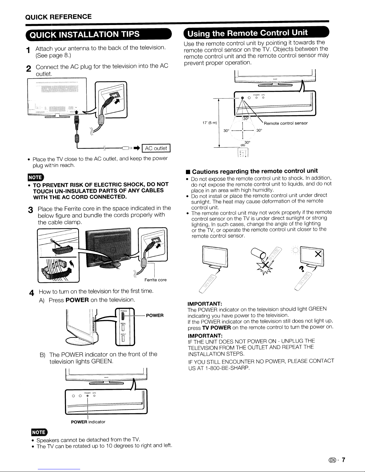
1 Confirm that there are 8 screws(4short screws
the
standinthe correct direction.
the
instructions. Incorrect installation of the stand may resultinthe TV falling over.
and 4 long screws) and a hex key supplied with the
stand unit.
to
mount it.
3
CD
Insert the stand into the openings on the bottom
of the
TV.
eg)
Insert and tighten the 4 short screws into the 4
holes on the rear of the
TV.
(x
1)
or
2 Attach the supporting post for the stand unit onto
the base using the box for the stand unit as shown
below.
•
The
supporting post attachestothe
location
on
the
base.Besure
the
direction indicated below
with
the
wider
sideofthe
, , "
---.j.
-
A
@)-
6
__
-"':
to attach
and
base
facing
Long screws
attach
baseatan
the
supporting post
the
standtothe
forward.
Hex key
Sllort screws
off-centered
in
TV
1m
• To detach the stand, perform the stepsinreverse order.
Page 8
QUICK
REFERENCE
QUICK
INSTALLATION
TIPS
1 Attach your antenna to the back of the television.
(See page
8.)
2 Connect the AC plug for the television into the AC
outlet.
• Place thelVclose to the AC outlet, and keep the
plug within reach.
power
mm
• TO PREVENT RISK OF ELECTRIC SHOCK, DO
TOUCH UN-INSULATED PARTS OF ANY CABLES
WITH
THEACCORD
3 Place the Ferrite core
below figure and bundle the cords properly with
the cable clamp.
CONNECTED.
in
the space indicatedinthe
NOT
Using the
Use the remote control unit by pointing
remote control sensor on the 1V. Objects between the
remote control unit and the remote control sensor may
prevent proper operation.
IT(5m)
Remote
II
J
~-----ll-
I
/~'"
17\'\.
-30~\~"",
I
30°
-,
-1-,.
---'----=~
Control Unit
0 0 0
'.
30°
30°
it
towards the
Remote control sensor
1
f8l
• Cautions regarding the remote control unit
• Do not expose the remote control unittoshock.Inaddition,
do not expose the remote control unit
place
in
• Do not install or place the remote control unit under direct
sunlight. The heat may cause deformation of the remote
control unit.
• The remote control unit may not work properly if the remote
control sensor on the
lighting.
or the
remote control sensor.
an area with high humidity.
In
such cases, change the angle of the lighting
lV,
or operate the remote control unit closer to the
lVisunder direct sunlight or strong
to
liquids, anddonot
4 How to turn
A)
Press POWER on the television.
B)
The POWER indicator on the front of the
television lights GREEN.
on
the television for the first time.
1""
"[I
110
f'QWE<lOf'(;
0 0
o 0
I
POWER indicator
J~
)1
Ferrite core
IMPORTANT:
POWER
Jl
The POWER indicator on the television should light GREEN
indicating you have power to the television.
If the POWER indicator on the television still does not light up,
press
IMPORTANT:
IF
TELEVISION FROM THE OUTLET AND REPEAT THE
INSTALLATION STEPS.
IF
US
TV POWER on the remote control to turn the power on.
THE UNIT DOES NOT POWERON- UNPLUG THE
YOU STILL ENCOUNTER NO POWER, PLEASE CONTACT
AT
1-800-BE-SHARP.
mm
• Speakers cannot be detached from the
• ThelVcan be rotated upto10 degreestoright and left.
lV.
(®-
7
Page 9
Preparation
Antennas .
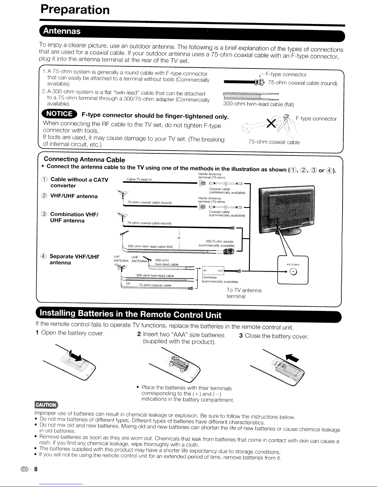
To enjoy a clearer picture, useanoutdoor antenna. The followingisa brief explanation of the types of connections
that
are
used for a coaxial cable.Ifyour outdoor antenna uses a 75-ohm coaxial cable withanF-type connector,
plugitinto the antenna terminal at the rear of the 1V set.
.A 75-ohm systemisgenerally a round cable with F-type connector
that can easily be attached to a terminal without tools (Commercially
available).
2.
A 300-ohm systemisa flat "twin-lead" cable that can be attached
to
a 75-ohm terminal through a 300/75-ohm adapter (Commercially
available).
~
F-type connector should be finger-tightened only.
----m
300-ohm twin-lead cable
r-F-type
75-ohm coaxial cable (round)
When connecting theRFcable to the 1V set, do not tighten F-type
connector with tools.
If
tools
are
used, it may cause damage to your1Vset.
(The
breaking
75-ohm coaxial cable
of internal circuit, etc.)
Connecting Antenna Cable
• Connect the antenna cable to the TV using one of the methodsinthe illustration as shown
.....
CD
Cable without a CATV
converter
® VHF/UHF antenna
@ Combination
UHF antenna
@ Separate VHF/UHF
antenna
VHF/
C,;;;ab.,le..TV..I,;;;ea..d-..ln
75-ohm coaxial cable (round) terminal (75-ohm)
Io0o-
75-ohrn coaxial cable (round)
I
or
30D-ohm twin-lead cable
\::==:::===~=~==
VHF
UHF
ANTENNA ANTENNA
300-ohm twin-lead cable r
~~=======::::i==
lor
75-ohm
~===============llt}
30D-ohm
twin-lead cable
coaxial cable
(flat)
Home
Antenna
terminal (75-ohm)
[!!Ii
CO>~\=<1
Coaxial
cable
(commercially available)
Home
Antenna
[!!Ii
CO>~\=<£3
Coaxial cable
(commercially available)
300175-ohm
(commercially available)
adapter
dl
~:mbiner
OUT~-""'----+-_
(commercially available)
ToTVantenna
terminal
connector
(flat)
"-
(CD,
(g),
M~T/CABLE
0
@
or
@).
Installing Batteriesinthe Remote Control Unit
If
the remote control fails to operate1Vfunctions, replace the batteriesinthe remote control unit.
1 Open the battery cover. 2 Insert two
~
Improper use of batteries can resultinchemical leakage or explosion. Be sure to follow the instructions below.
• Do not mix batteries of different types. Different types of batteries have different characteristics.
• Do not mix old and new batteries. Mixing old and new batteries can shorten the life of new batteries or cause chemical leakage
in
old batteries.
• Remove batteries as soon as they are worn out. Ctlemicals that leak from batteries that comeincontact with skin can cause a
rash.
If
• The batteries supplied with this product may have a shorter life expectancy due to storage conditions.
•
C®-
8
you find any chemical leakage, wipe thoroughly with a cloth.
If
you will not be using the remote control unit foranextended period of time, remove batteries from
"AM"
size batteries 3 Close the battery cover.
(supplied with the product).
• Place the batteries with their terminals
corresponding to the (
indications
In
the battery compartment.
+)and (- )
it.
Page 10
Contents
IMPORTANT INFORMATION 1
Trademarks 2
DEAR SHARP CUSTOMER 3
IMPORTANT SAFETY INSTRUCTIONS 3
Supplied
j~ccessories
QUICK REFERENCE 6
Attaching the Stand 6
QUIO(
Using the Remote Control Unit 7
INSTALLATION TIPS 7
Preparatil:>n 8
Antennas 8
Installing Batteriesinthe Remote Control Unit 8
Contents" 9
Part Nam,es 10
TV
(Front) 10
TV
(RElar/Side)
Remote Control Unit
Connecting to External Equipment
Connecting Audiovisual Equipment 12
Using Digital Audio Output. 13
Connecting HDMI Equipment 13
Connecting a PC 13
10
11
12
Watching TV 14
Turning On/Off the Power 14
Initial Setup 14
Direct Button Operation 15
Changing Channels 15
Changing Volume 15
MUTE 15
Sleep Timer 15
FLASHBACK 15
SURROUND 15
FRE:EZE
INFlUT 15
AV
MODE 16
AUDIO 16
POWER SAVING 17
Closed Captions and
VIEW MODE 18
Digital
Closed Captions 17
15
On-Screen Display Menu 19
Menu Items 1g
On-Screen Display Menu Operation 20
Menu Operation Buttons 20
Picture Menu
OPC Setting
Advanced Picture Setting
Audio Menu 22
Surround 22
Bass Enhancer 22
Power Control Menu 23
Power Saving 23
No Signal Off 23
No Operation Off 23
Setup Menu 23
EZ
Setup 23
CH
Setup 24
Antenna Setup-DIGITAL 24
Input Skip 24
Input Label 24
Auto Sync. (for AnalogPCInput Mode
Only)
21
21
21
24
Fine Sync 24
Position 25
Language 25
Reset 25
6
Parental CTRL (Parental Control Setting) 25
Option Menu 28
Audio Only 28
Color System 28
Input Select 28
HDMI Setup 28
PC Audio Select.. 28
Output Select 29
Caption Setup 29
Digital Caption Info.
(Digital Caption Information) 29
Program Title Display 29
Game Play Time 29
Operation Lock Out 29
Favorite CH (Favorite Channel Setting) 29
Demo Mode 29
Digital Setup Menu 30
Audio Setup 30
Identification 30
Software Update 30
Other Viewing Options 32
Presetting Remote Control Function 32
Operating the Connected Equipment 32
Using AQUOS LINK 34
Controlling
AQUOS LINK Setup 35
One Touch Recording 35
One Touch Playback 36
AQUOS LINK Menu 36
Timer Recording 36
Playback of Titles Using
Selecting Media Type for
Listening with the AQUOS AUDIO
Manually Changing AQUOS AUDIO
Displaying the Setup Menu of
HDMI Device Selection 37
HDMI
Equipment
AQUOS LINK-Compatible Recorder 37
Speaker System 37
Speaker System's Sound Mode 37
AQUOS LINK-Compatible Equipment 37
Using
AQUaS
AQUaS
LINK 37
Appendix 38
Removing the Stand 38
Setting theTVon
Troubleshooting 39
Troubleshooting-Digital Broadcasting 39
RS-232C Port Specifications 40
Specifications
Optional Accessory
PC
Compatibility Chart 42
Information on the Software License for This
Product 42
the Wall 38
Calling for Service 43
LIMITED WARRANTY 43
Dimensional Drawings
• The dimensional drawings for the LCD TV set are shown
on the inside back cover.
LINK
34
.41
.41
@-9
Page 11
Part Names
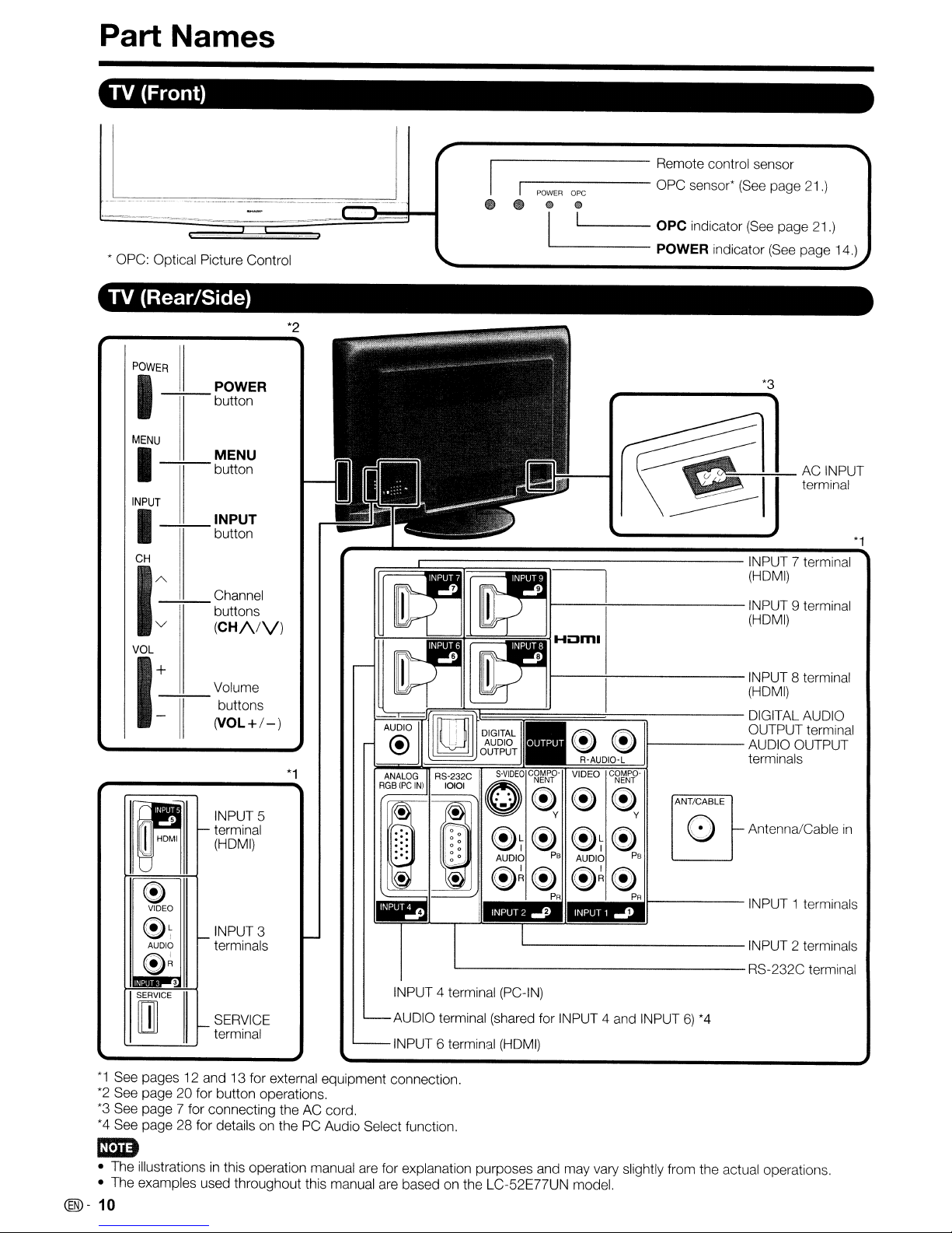
TV (Front)
• OPC: Optical Picture Control
TV (Rear/Side)
PIOWE---i7R
11_
POWER
button
MENU
-+;--
I
INPUT
-+;--
I
CH
----;-;-
AV-----'-'-------
1
VOL
--:+--
I:
II
MENU
button
INPUT
button
Channel
buttons
(CH/VV)
Volume
buttons
(VOL+/-)
INPUT 5
terminal
"-
(HDMI)
'1---------
'I
-------
POWER
e _
*2
r==....1::::::::::::::::::;::::::::::::::::::::::::::::::::::===:::::--------
!--
__
*1
~;rF===='T=~~~~~:§R~.A~UD~IO§:-~L
~T~
AUDIO
ope
C!)
Q)
I 1 OPC indicator
------
I----\--------INPUT
I---+---------INPUT
=====t==:::::::;------
~ ~
VIDEO
~~
~T~
PB
AUDIO
Remote control sensor
OPC sensor*
POWER indicator
~
11------
~
c~~~.p-
ANT/CABLE
y
o
PB
(See
page 21.)
(See
page 21.)
(See
page 14.)
*3
INPUT 7 terminal
(HDMI)
9 terminal
(HDMI)
8 terminal
(HDMI)
DIGITAL AUDIO
OUTPUT terminal
AUDIO OUTPUT
terminals
"-
Antenna/Cable
~
*1
in
e
VIDEO
"
~~
AUDIO
INPUT 3
"-
terminals
e~
3
SERVICE
SERVICE
m
*1
See pages12and 13 for external equipment connection.
*2
See page 20 for button operations.
*3
See page 7 for connecting the AC cord.
*4
See page 28 for details on the PC Audio Select function.
"-
terminal
ImD
• The illustrationsinthis operation manual are for explanation purposes and may vary slightly from the actual operations.
• The examples used throughout this manual are based on the LC-52E77UN model.
(®-
10
~~~ ~~~
PA PA
L-
L-
INPUT 4 terminal (PC-IN)
AUDIO terminal (shared for INPUT 4 and INPUT
INPUT 6 terminal
(HDMI)
>...------
INPUT 1 terminals
INPUT 2 terminals
RS-232C terminal
6)
*4
Page 12
Part
Names
Remote
10-~e~(
11
12
13
14
15
16
Control
2
--~~S~O~UA~C~E=::::;----='''
3
--..:---:.
4
5
6
7
8
9 •
\
I
----:---V-OL-~H
--'7--.
I•
----.JI'-i~!:;:::[
---;,:-:-,
~i.
I i SLEEP AUDIO
--\:-:-\i,-il.-
----'1'"'"\
'-'-..t-J
Unit
17
REC
•
--
•
--
-,-
•
• •
•
• •
•
•
• •
INPUT
• • •
FlASHBACK
I
--:---
1
.~,-
~~~~~
,
'MUTE
FREEZE
.:~,
FiA1Ti
R~EC~ST~OP~O~PT~'~~-~-~--~F::::-AV~O~RrT~E1~lrl!
.
H
AV
MODE
i
---------J
I
..-:-----
MENU
,
I :
•
4t]---:I-
.,-'-,
':"';'11--
CC
i'
!
·:-'-!";';!!I-I
18
19
20
21
22
23
26
27
28
~~
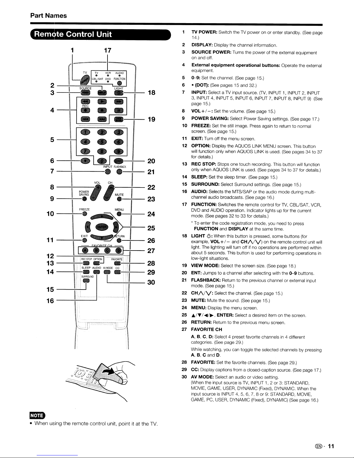
TV POWER: Switch the TV power onorenter standby. (See page
14.)
2 DISPLAY: Display the channel information,
SOURCE POWER: Turns the power of the external equipment
3
on and off.
4
External
equipment.
5
0-9:
6 •
7
INPUT: Select a TV input source,
3, INPUT
page 15.)
8
VOL+/
POWER SAVING: Select Power Saving settings. (See page 17.)
9
10 FREEZE: Set the still image. Press again
screen. (See page 15.)
11
EXIT: Turn off the rnenu screen,
12
OPTION: Display the AQUOS LINK MENU screen. This button
will function only when AQUOS LINK is used. (See pages 34
for details.)
13
REC STOP: Stops one touch recording. This button will function
only when AQUOS LINK is used, (See pages 34
14
SLEEP: Set the sleep timer. (See page 15,)
15
SURROUND: Select Surround settings. (See page 15.)
16
AUDIO: Selects the MTS/SAP
channel audio broadcasts, (See page 16.)
17
FUNCTION: Switches the remote control for TV, CBUSAT, VCR,
DVD and AUDIO operation, Indicator lights
mode, (See pages 32
• To enter the code registration mode, you need
18
LIGHT
example,
light. The lighting will turn off
about 5 seconds. This button is used for perforrning operations
low-light situations.
19
VIEW MODE: Select the screen size. (See page 18.)
20
ENT:
21
FLASHBACK: Return
mode. (See page 15.)
22
CH/VV:
23
MUTE: Mute the sound, (See page 15.)
24
MENU:
25
A/T
26
RETURN: Return
27 FAVORITE
A, B, C, D: Select 4 preset favorite channelsin4 different
categories. (See page 29.)
While watching, you can toggle the selected channels by pressing
A, B, C and
28
FAVORITE: Set the favorite channels. (See page 29.)
CC: Display captions from a closed-caption source.
29
30
AV MODE: Select an audio or video setting.
(When the input source
MOVIE, GAME, USER, DYNAMIC (Fixed), DYNAMIC. When the
input source is INPUT
GAME, PC, USER, DYNAMIC (Fixed), DYNAMIC) (See page 16.)
equipment
Set the channel. (See page 15.)
(DOn:
(See pages 15 and 32.)
4,
INPUT5,INPUT6,INPUT7,INPUT8,INPUT9)(See
-:
Set the volurne. (See page 15.)
FUNCTION and DISPLAY at the same time,
.¢.-:
When this buttonispressed, some buttons (for
VOL+/- and
Jumpstoa channel after selecting with the
Select the channel. (See page 15.)
Display the menu screen.
/
~/~,
CH
D.
operational
to
33 for details.)
CH/\/V)
to
the previous channel or external input
ENTER: Select a desired item on the screen.
to
the previous menu screen,
is
4,5,6,7,8or
buttons:
(TV,
INPUT1,INPUT 2, INPUT
to
returntonorrnal
or
the audio mode during multi-
up
on the rernote control unit will
ifnooperations are performed within
TV,
INPUT
1,2or3:
9: STANDARD, MOVIE,
Operate the external
to
37 for details.)
for the current
to
press
0-9
buttons.
(See
STANDARD,
to
37
page 17.)
in
em
• When using the remote control unit, pointitat the
TV
@-
11
Page 13
Connecting to External Equipment
You can connect many types of external equipment to your1Vlike a Blu-ray disc player,
1V
tuner, HDMI equipment, game console or camcorder. To view external source images, select the input source
from
INPUT on the remote control unit or on the 1V.
(See
page 15.)
DVD
player,
VCR,
E1'!imD
• To protect equipment, always turn off the1Vbefore connecting any external equipment.
• Please read the relevant operation manual (Blu-ray disc player. etc.) carefully before making conneclions.
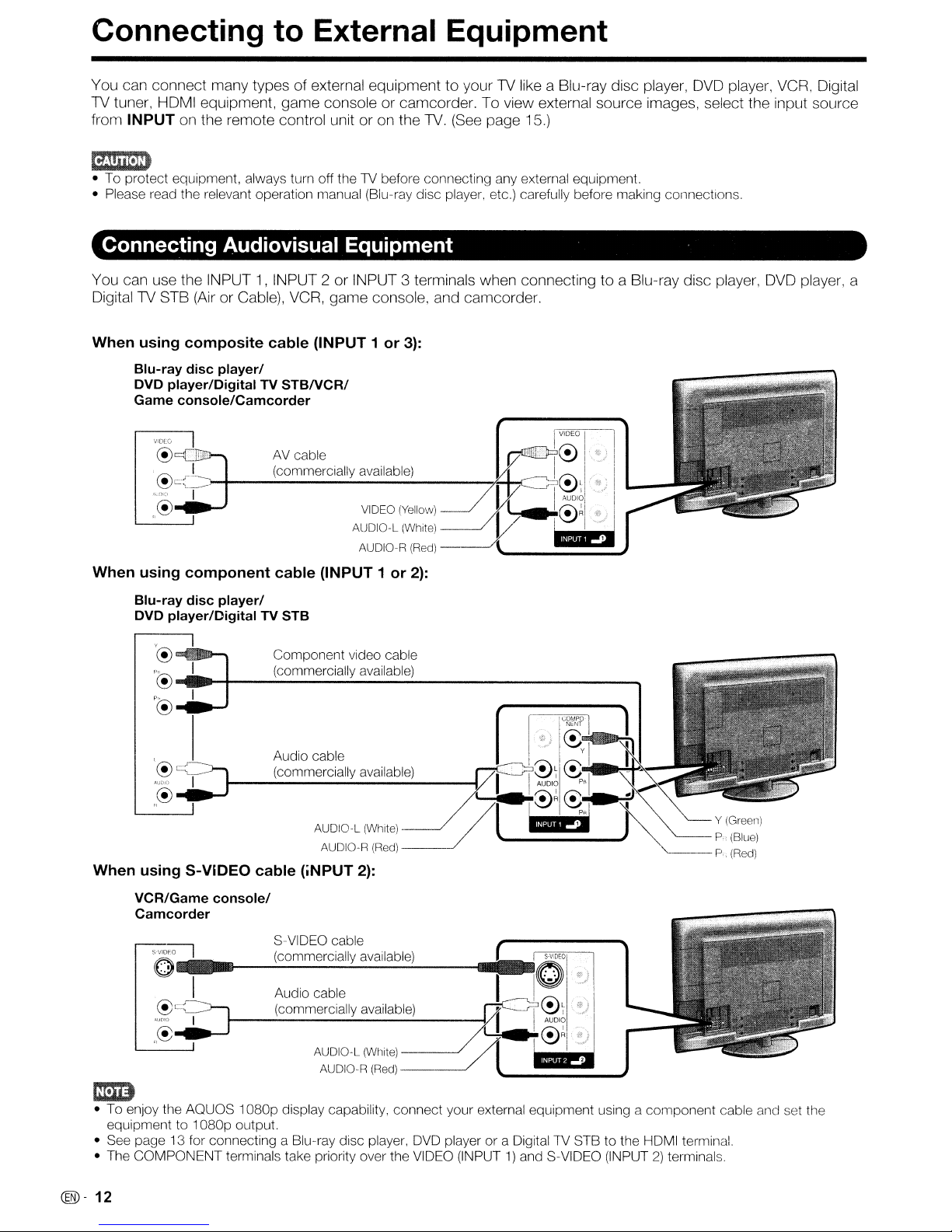
Connecting Audiovisual Equipment
You can use the INPUT1,INPUT 2 or INPUT 3 terminals when connecting to a Blu-ray disc player,
Digital1V STB
When using composite cable (INPUT 1 or
Blu-ray disc player/
DVD player/Digital TV
Game console/Camcorder
VIDEO
(Air
or Cable),
VCR,
game console, and camcorder.
STBNCR/
3):
DVD
Digital
player, a
When using component cable (INPUT 1 or
Blu-ray disc player/
DVD player/Digital TV STB
'@
.....
p®
"'.H
p®
.....
, I
_""""
..J
Component video cable
__
.-;..(c_o_m_m_e_rc_i_al..;;,ly_a_v_a_ila_b_le_)
Audio cable
2):
(commerCiaIlYavailab~e)
:~~
AUDIO-L(White) /
AUDIO-R
When using S-VIDEO cable (iNPUT
VCR/Game console/
Camcorder
SVID~
S-VIDEO cable
(commercially available)
O-"-~~~:::::'::::':::':"'--"---"
I Audio cable
@~
,":.~_I
._r-------~-----
,,@
em;:)
• To enjoy the AOUOS
equipment
• See page 13 for connecting a Blu-ray disc player, DVD player
• The
to
1080p
COMPONENT
terminals take priority over the VIDEO (INPUT1)and S-VIDEO (INPUT2)terminals.
(commercially available)
AUDIO-L (White)
AUDIO-R
1080p
display capability,
output.
2):
(Red)
(Red)
~
-----'
---~
connect
your external equipment using a
COMPO
NENT
C!)
....
I
i.
Vf:I~~
~~RC!).
/l
.1@ilE;
oraDigital1V
y I
~.·p'l·
STBtothe HDMI terminal.
....
~'~
~.~
~J
~Y
component
..
(Greell)
P.(Blue)
P
(Red)
cable and set the
@-
12
Page 14
Connecting to External Equipment
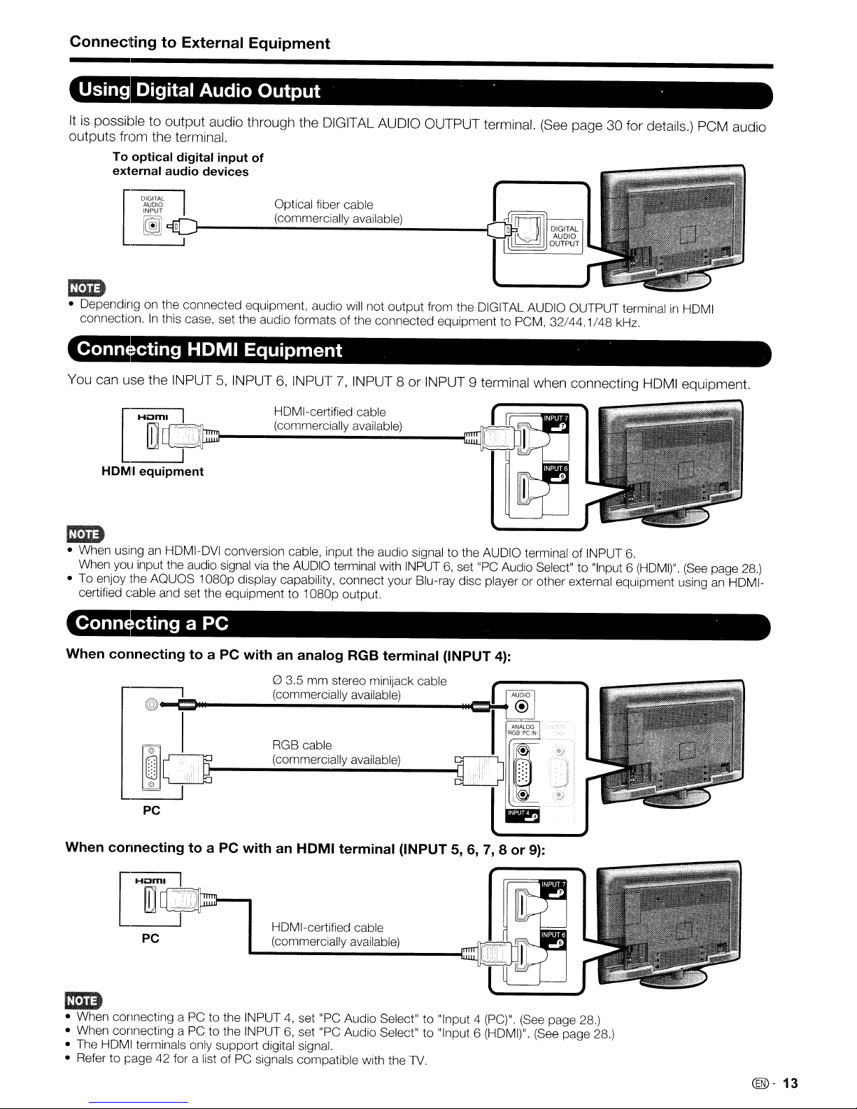
Using Digital Audio Output . .
Itispossible to output audio through the DIGITAL AUDIO OUTPUT terminal.
outputs from the terminal.
To optical digital input
external audio devices
D1Sg,~
INPUT
~
9Of-
of
Optical fiber cable
.....;(c_o_m_m_e_rc_ia_lI.;.y_a_va_i_la_b_le.;..)
__
(See
page 30 for details.) PCM audio
crm
• Depending on the connected equipment, audio will not output from the DIGITAL AUDIO OUTPUT terminalinHOMI
connection.Inthis case, set the audio formatsofthe connected equipment to PCM,
Connecting
You can use the INPUT5,INPUT6,INPUT7,INPUT 8orINPUT 9 terminal when connecting HDMI equipment.
~
~
HOM
I
equipment
HDMI
Equipment
HDMI-certified cable
(_co_m_m_e_rc_ia_I_IY_a_V_ai_la_b_le_)
_
32/44.1/48
kHz.
crm
• When using an HDMI-DVI conversion cable, input the audio signaltothe AUDIO terminal of INPUT
When you input the audio signal via the AUDIO terminal with INPUT6,set "PC Audio Select" to "Input 6
• To enjoy the
certified cable and set the equipmentto1
Connecting a PC
When connectingtoa PC with an analog RGB terminal (INPUT
When connecting to a PC with an
AQUaS1080p
display capability, connect your Blu-ray disc player or other external equipment using an HDMI-
080p
output.
o 3.5
mm
stereo minijack cable
(commercially available)
@~=---------------e:~-+
RGB cable
(commercially available)
PC
I
Hill
PC
,j-
HOMI
:::::I----t
HOMI-certified cable
(commercially available)
terminal (INPUT 5,
6,7,8
4):
or
9):
6.
(HDMI)".
(See
page 28.)
crm
• When connecting a PCtothe INPUT4,set "PC Audio Select"to"Input 4 (PC)". (See page 28.)
• When connecting a PCtothe INPUT6,set "PC Audio Select" to "Input 6 (HDMI)". (See page 28.)
• The HDMI terminals only support digital signal.
• Refer
to
page 42 for a list of PC signals compatible with the
TV.
@-
13
Page 15
Watching TV
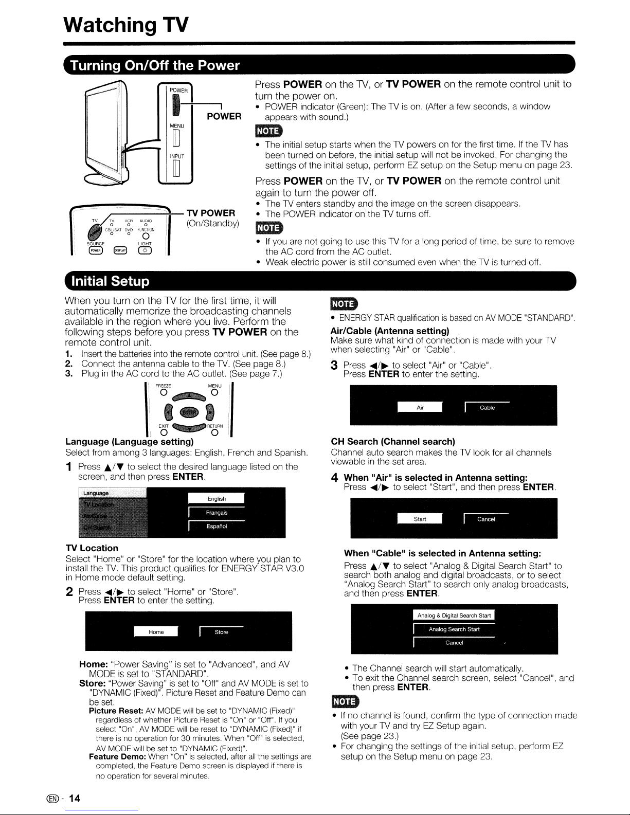
Turning On/Off the Power
Press POWER on the
turn the power on.
Pil-ER-+-P-O....,~ER
U
• POWER indicator (Green): TheTVis
appears with sound.)
I5D
m
INPUT
m
,...-----+1'
TV
/r,V
•
.,
SOURCE
8 8
VCR
CB~/SAT
D~D
FUN~TION
0 0 0
@)
Initial Setup
When you turn on the TV for the first time, it will
automatically memorize the broadcasting channels
available
following steps before you press TV POWER on the
remote control unit.
1. Insert the batteries into the remote control unit.
2. Connect the antenna cable to the TV. (See page
3. Plug
in
the region where you
in
the AC cordtothe AC outlet. (See page 7.)
r--
TV POWER
AUO'O
:li'lll
(On/Standby)
LIGHT
i
FREEZE
: 0 0 I
i J 4 I
live.
MENU
• The initial setup starts when the TV powers on for the first time.Ifthe TV has
been turned on before, the initial setup will not be invoked. For changing the
settingsofthe initial setup, performEZsetup on the Setup menu on page 23.
Press POWER on the
again to turn the power off.
• The TV enters standby and the image on the screen disappears.
• The POWER indicator on the
I5D
•Ifyou are not going to use this TV for a long periodoftime, be suretoremove
the AC cord from the AC outlet.
• Weak electric power
Perform the
(See
page
8.)
'/
TV,
or TV POWER on the remote control unit to
on. (After a few seconds, a
TV,
or TV POWER on the remote control unit
TV
turns off,
is
still consumed even when the TVisturned off.
I5D
•
ENERGY
Air/Cable (Antenna setting)
Make sure what kindofconnectionismade with your TV
when selecting "Air"
8.)
3 Press
Press
STAR
qualificationisbasedonAV
or
"Cable".
..../~to
ENTER
select "Air" or "Cable".
to
enter the setting.
MODE
window
"STANDARD".
:i:
,1---
Language (Language setting)
Select from among 3 languages: English, French and Spanish.
1 Press
TV Location
Select "Home"or"Store" for the location where you plan to
install the
in
2 Press
J;./~
screen, and then press
TV.
Home mode default setting.
..../~to select "Home" or "Store".
Press
ENTER to enter the setting.
Home: "Power Saving"
MODE
Store: "Power Saving"
"DYNAMIC
set.
be
Picture Reset:
regardless of whether Picture Reset
select "On",
thereisno operation for 30 minutes, When "Off"isselected,
AV
MODE will be set to "DYNAMIC (Fixed)".
Feature Demo: When "On"
completed, the Feature Demo screen
no operation for several minutes.
I
to
select the desired language listed on the
This product qualifies for ENERGY STAR V3.0
is
set
to
"STANDARD".
(Fixed)".
Picture Reset and Feature Demo can
AV
MODE will be setto"DYNAMIC (Fixed)"
AV
MODE will be resetto"DYNAMIC (Fixed)"
"~o·1
ENTER.
is
set to "Advanced", and AV
is
set to "Off" andAVMODEisset to
is
"On"or"Off".Ifyou
is
selected, after
all
the settings are
is
displayedifthere
if
is
CH Search (Channel search)
Channel auto search makes the TV look for
viewable
4
in
the set area,
When"
Press
When "Cable"
Press
search both analog and digital broadcasts, or
"Analog Search Start" to search only analog broadcasts,
and then press
• The Channel search will start automatically,
• To exit the Channel search screen, select "Cancel", and
Air"isselectedinAntenna setting:
..../~to
J;./~
then press
select "Start", and then press ENTER.
is
selectedinAntenna setting:
to select "Analog & Digital Search Start" to
ENTER.
ENTER.
all
channels
to
select
I5D
•Ifno channelisfound, confirm the type of connection made
with your
(See page 23.)
• For changing the settings of the initial setup, perform EZ
setup on the Setup menu on page 23.
TV
and tryEZSetup again.
@-14
Page 16
Direct Button Operation
El
8
•
• •
• •
•
•
• • •
INPUT
R.ASHBACK
• •
••
VOL CH
ro~RII
SAiO
M.E
FREEZE
.~O
888
EXIT
<::::::::!:::::
o • 0
- FAVORITECH-
0
REC
00
SLEEP AUDIOAVMODE
••••
SURROUND
•
STOP
®
OPTION
@ @
MENU
RETURN
FAVORITE
0
CC
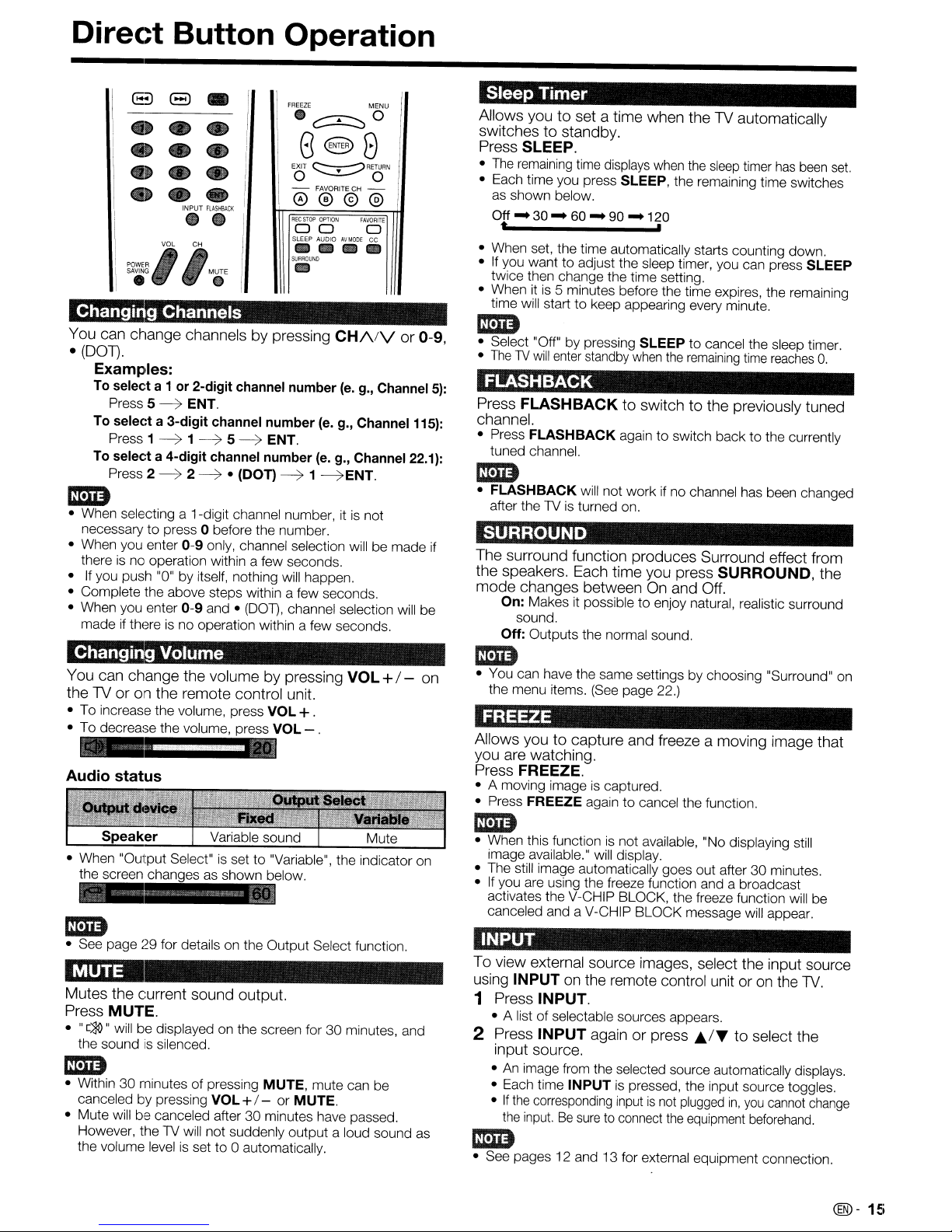
Changing Channels
You can change channels by pressing
(DOT).
•
Examples:
To select a 1or2-digit
Press 5
To
Press 1
To
Press 2
1m
• When selecting a 1-digit channel number, itisnot
necessary
• When you enter
thereisno operation within a few seconds.
•Ifyou push "0"byitself, nothing will happen.
• Complete the above steps within a few seconds.
• When you enter
made if there is no operation within a few seconds.
~
ENT.
selecta3-digit
~1~
selecta4-digit
~2~
to
press 0 before the number.
0-9
0-9
channel
channel
channel
only, channel selection will be made if
and •
5~
number
• (DOT)
(DOT),
number
ENT.
~1~ENT.
CH/\/V
number
channel selection will be
(e.
g., Channel
(e. g., Channel 115):
(e.
g., Channel 22.1):
Changing Volume
You can change the volume by pressing
TVoron
the
• To increase the volume, press VOL+.
• To decrease the volume, press VOL - .
Audio
the remote control unit.
status
VOL
or 0-9,
+/- on
Sleep
Allows you to set a time when the TV automatically
switches to standby.
Press SLEEP.
•
• Each time you press SLEEP, the remaining time switches
• When set, the time automatically starts counting down.
•
• When it
1m
• Select "Off"bypressing SLEEPtocancel the sleep timer.
•
5):
FLASHBACK
Press
channel.
• Press
1m
•
Timer
The
remaining time displays when the
as shown below.
Off - 30 - 60 - 90 - 120
t ,
If
you wanttoadjust the sleep timer, you can press SLEEP
twice then change the time setting.
time will start
ThelVwill
tuned channel.
FLASHBACK
after the TV is turned on.
is
5 minutes before the time expires, the remaining
to
keep appearing every minute.
enter standby
FLASHBACK
FLASHBACK
will not work if no channel has been changed
when
to switch to the previously tuned
againtoswitch backtothe currently
the
sleep
remaining
timer
time
SURROUND
The surround function produces Surround effect from
the speakers. Each time you press SURROUND, the
mode changes between
On:
Makes it possibletoenjoy natural, realistic surround
sound.
Off:
Outputs the normal sound.
1m
• You can have the same settings by choosing "Surround" on
the menu items. (See page 22.)
On
and Off.
FREEZE
Allows you to capture and freeze a moving image that
you are watching.
Press FREEZE.
• A moving imageiscaptured.
• Press
FREEZE again
to
cancel the function.
has
been
reaches
set.
O.
1m
• See page29for details on the Output Select function.
MUTE
Mutes the current sound output.
Press MUTE.
•
"[~"
will be displayed on the screen for 30 minutes, and
the soundissilenced.
mm
• Within30minutes of pressing MUTE, mute can be
canceled by pressing VOL+I - or MUTE.
• Mute will be canceled after30minutes have passed.
However, the TV will not suddenly output a loud sound as
the volume levelisset to 0 automatically.
1m
• When this functionisnot available, "No displaying still
image available." will display.
• The still image automatically goes out after
If
you are using the freeze function and a broadcast
•
activates the V-CHIP BLOCK, the freeze function will be
canceled and a V-CHIP BLOCK message will appear.
30
minutes.
INPUT
To view external source images, select the input source
using
INPUTonthe remote control unit oronthe
1 Press INPUT.
• A list of selectable sources appears.
2 Press
1m
• See pages 12 and 13 for external equipment connection.
INPUT
input source.
•Animage from the selected source automatically displays.
• Each time
•Ifthe
corresponding inputisnot
the
input.Besure
again or press J;,./T to select the
INPUT is pressed, the input source toggles.
to connect
plugged
the
in,
equipment
you
beforehand.
cannot
TV.
change
@-
15
Page 17
Direct
Button
Operation
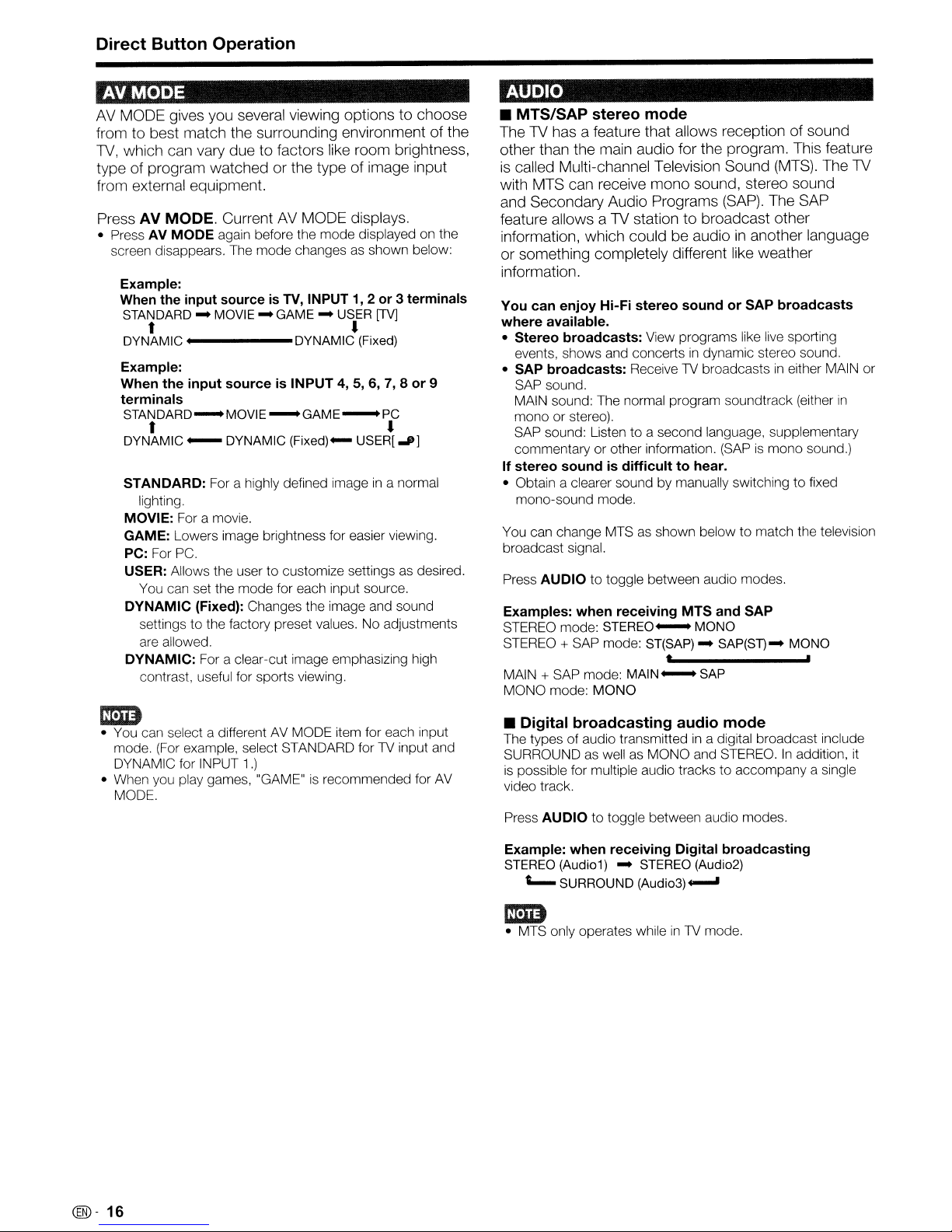
AVMODE
AV
MODE gives you several viewing optionstochoose
from to best match the surrounding environment of the
1V, which can vary due to factors like room brightness,
type of program watched or the type of image input
from external equipment.
Press AV MODE. Current
• Press AV MODE again before the mode displayed on the
screen disappears. The mode changes
Example:
When the input source is
STANDARD-MOVIE-GAME-USER
t •
DYNAMIC DYNAMIC
Example:
When
the
input
sourceisINPUT 4, 5, 6, 7, 8
terminals
STANDARD-MOVIE
AV
MODE displays.
as
shown below:
TV,
INPUT1,2or3 terminals
[TV]
(Fixed)
-GAME-PC
or
9
t •
DYNAMIC - DYNAMIC
STANDARD: For a highly defined image
lighting.
MOVIE: For a movie.
GAME: Lowers image brightness for easier viewing.
PC: For
USER: Allows the user to customize settings
DYNAMIC (Fixed): Changes the image and sound
DYNAMIC: For a clear-cut image emphasizing high
PC.
You can set the mode for each input source.
settings to the factory preset values. No adjustments
are allowed.
contrast, useful for sports viewing.
(Fixed)-
USER!..P]
in
a normal
as
desired.
AUDIO
• MTS/SAP
The1Vhas a feature that allows reception of sound
other than the main audio for the program. This feature
is
called Multi-channel Television Sound
with MTS can receive mono sound, stereo sound
and Secondary Audio Programs
feature allows a
information, which could be audio
or something completely different like weather
information.
You can
where
available.
• Stereo
events, shows and concerts
• SAP
broadcasts:
SAP sound.
MAIN sound: The normal program soundtrack (either
mono or stereo).
SAP sound: Listen to a second language, supplementary
commentary or other information. (SAP
If
stereo
• Obtain a clearer sound by manually switching to fixed
mono-sound mode.
You can change MTS
broadcast signal.
AUDIO to toggle between audio modes.
Press
Examples:
STEREO mode:
STEREO + SAP mode:
MAIN + SAP mode:
MONO mode: MONO
stereo
enjoy
broadcasts:
soundisdifficulttohear.
when
mode
1V
station to broadcast other
Hi-Fi
stereo
soundorSAP
View programs like live sporting
in
dynamic stereo sound.
ReceiveTVbroadcastsineither MAIN or
as
shown below to match the television
receiving MTS
STEREO-
ST(SAP)-SAP(ST)
MAIN-SAP
MONO
t
(MTS).
(SAP).
The SAP
in
another language
broadcasts
is
mono sound.)
and
SAP
- MONO
The
1V
in
ED
• You can select a different AV MODE item for each input
mode.
(For
example, select STANDARD forTVinput and
DYNAMIC for INPUT
• When you play games, "GAME"isrecommended for
MODE.
1.)
AV
• Digital
The types of audio transmittedina digital broadcast include
SURROUND
is
possible for multiple audio tracks to accompany a single
video track.
Press
Example:
STEREO
L..
broadcasting
as
wellasMONO and STEREO.Inaddition,
AUDIO to toggle between audio modes.
when
receiving Digital
(Audio1) SURROUND
audio
mode
broadcasting
STEREO
(Audio3)~
(Audio2)
ED
• MTS only operates whileinTV
mode.
it
@-
16
Page 18

Direct
Button
Operation
POWER SAVING
Allows youtoset the Power Saving levelinorder
decrease the power consumption and increase the
backlight lifespan.
Press POWER SAVING.
I Each time you press POWER SAVING, the mode changes
as shown below.
..
Standard"
Off
t ,
1m
I You can have the same settings by choosing "Power
Saving" on the menu items. (See page 23.)
I
.•
~.
lVisequipped withaninternal Closed Caption
Your
decoder. It allows you
and sound effects as subtitles on your
Captions are available on some
some VHS home video tapes at the discretion
program provider.
Digital Closed Caption seNiceisa new caption seNice
available only on
discretion of the seNice provider).
system than the original Closed Caption system,
it
because
styles. When the Digital Closed Caption seNice
use,itwill be indicated by the appearanceofa 3-letter
abbreviation that also indicates the language of the
Digital Closed Captions:
FRA
Not
captions. Please look for the
that captions will be shown.
In
the
one caption seNice provided. Each
own number. The
subtitles
program's picture.
In
the Closed Caption system, the "Text1" or "Text2"
seNices display text that
being viewed (e.g., weather or news). These seNices
are also superimposed over the program currently
being viewed.
allows for a varietyofcaption sizes and font
(French) or other language codes.
all
programs and VHS videotapes offer closed
C10S13d
oflVprograms superimposed over the
Advanced
!.tm.m!m!I!Imm
to
view conversations, narration
lV.
lV
programs and on
digitallV
Caption system, there can be more than
"CC1
programs (also at the
Itisa more flexible
ENG
(English), SPA (Spanish),
"[ccr
symbol to ensure
is
identified by its
" and "CC2" seNices display
is
unrelated to the program
Closed
of
is
to
the
in
1 Press ee.
I This will present the Closed Caption information
display.
2 Press ee while the Closed Caption information
still on the screen.
I Press repeatedly until you select the desired closed
caption service.
Air DIGITAL
22.1
Audio
Video
ee
Ratings
I Depending on the number of caption services
signal being received, you will see information such as
1/2 or
1/4
displayed.
1/2 means "the first
Example:
If a program has three services (Digital CC(ENG),
and Text1),the closed caption display will toggleinthis
sequence:
....
t ,
I The
CC
button keeps a recordofthe last service
selected
If
selected
another channel, the closed caption service that
availableisautomatically selected, and this service
appears
Closed Caption services that appear
not be storedintheCCbutton's memory as your last
selected service. Only services that you have selected
with the
Examples:
In
a case where there are
seNices provided (for instance, Digital CC(ENG)
and CC1), and Digital CC(ENG)
as your current selection, if Digital CC(ENG)
not broadcast for the next program, the other
closed caption seNice, CC1, will be displayed
parentheses.
A closed caption seNice appears
because the seNice you selected
and a different seNice
"1/1(CC1)"
in
its memory.
the last closed caption mode (e.g. 1/3
is
not available for the next program, or on
in
parentheses, e.g. "1/3(CC1)".
CC
button are stored.
is
displayed instead of "1/2/ENG".
J.fJ
MONO
10801(169)
1/2
eel
NONE
of
two
_
is
Closed Caption
information
in
the
services".
.......
ENG)
you
in
parentheses will
two
closed caption
is
displayed
is
in
parentheses
is
not available
displayed on your screen.
is
CC1
is
in
1m
I When "Power Saving"
the Power Saving leaf icon appears on the channel
information window. See page 23 for details of Power
Saving settings.
I See page 29 for detailed closed caption settings.
I When the program contains no closed caption, "--" displays
in
the closed caption information.
I If the language code, e.g. "ENG",
programs, "
I Four kinds of closed caption service (CC1, CC2, Text1,
Text2) are potentially available, but a broadcast may contain
none or only some
program provider.
..
" will be shown.
is
setto"Standard" or "Advanced",
is
not found on Digital1V
of
these services at the discretion of the
@J-17
Page 19

Direct Button Operation
VIEW MODE
You can select the screen size.
1 Press VIEW MODE.
• The View Mode menu displays.
• The menu lists the View Mode options selectable for the type of video signal currently being received.
2 Press VIEW
• You can sequentially select a View Mode that has its
• For 4:3 programs
Example: Screen size images
MODE
Side Bar S.Stretch (Smart stretch)
or
1;,..1""
while the View Mode menuisdisplayed to select a desired item on the menu.
own
aspect ratio.
Zoom
Stretch
IMI
Suitable for viewing Suitable for stretching 4:3
conventional 4:3 programs
their normal format.
• For
HD
Stretch: Suitable for viewing wide-screen 1.78:1 aspect ratio program, stretch
Dot by Dot (1080i/p only): Detects the resolution
Full Screen (720p only): You can select "Full Screen" only when receiving a
S.Stretch (Smart stretch): Suitable for stretching 4:3 programs
Zoom: Suitable for viewing wide-screen 2.35:1 aspect-ratio programs
programs
top
and
the
the screen.
bottom
mm
• When using Dot by Dot or
change view mode to correct this.
• For PC input mode
mm
• Connect the PC before making adjustments. (See page 13.)
• Selectable screen size may vary with input signal type.
Example: Screen size images
Input signal
in
programstofill
of the screen.
Full
Screen, itispossible to see noise or bars around different outer portions of the screen. Please
the screen. screen 2.35:1 anamorphic
of
the signal and displays an image with the same numberofpixels on
Normal Zoom Stretch Dot by Dot
LITI
Suitable for viewing wide-
in
DVDs
to
fill
bQ)
full screen.
nop
the screen.
in
full screen.
1:0:1
This
modeisuseful
DVDs.
When
viewing
DVDs,
stretch
mode
very
thin
black
bandsatthe
and
bottomofthe
mode
will still show very thin black bands at
signal.
for
1.781
1,851
will
screen,
still
show
top
IIII
4:3
Input signal
16:9
@-
18
Keeps the original For viewing An image fully fills the
aspect ratio
screen display. programs. The
[IT]
An image fully fills the Detects the resolution
screen.
in
Stretch
a full
[]]
widescreen screen. of the
top
and
bottomofthe
imageiscropped.
Dot
by Dot
[0]
IQI
Detects the resolution
displaysanimage with
the
pixelsonthe screen.
[QJ
of the signal and
displays
the same number of
pixels
an
on
the screen.
image with
signal
same
and
number of
Page 20

On-Slcreen Display Menu
Menu
For
Picture
OPC Page
Backlight.. Page
Contrast Page
Brightness Page
Color Page
Tint Page
Sharpness Page
Advanced
Reset Page
Audio
Treble Page 22
Bass Page 22
Balance Page 22
Surround Page 22
Bass Enhancer Page
Reset Page
terns
TV/INPUT
Menu
C.M.S.-Hue Page
C.M.S.-Saturation Page
C.M.S.-Value Page
Color Temp Page
Fine Motion Enhanced Page
Active Contrast Page
Gamma Adjustment.. Page 22
Film Mode Page
Digital Noise Reduction Page 22
3D-Y/C Page 22
Monochrome Page 22
Range of OPC Page 22
Menu
1/2/3
Mode
For
HDMI/PC-IN
Picture Menu
21
21
21
21
21
21
21
21
21
21
21
21
21
22
21
22
22
OPC Page
Backlight. Page
Contrast Page
Brightness Page
Color Page
Tint Page
Sharpness Page
Advanced
C.M.S.-Hue Page
C.M.S.-Saturation Page
C.M.S.-Value Page
Color Temp Page
Fine Motion Enhanced Page
Active Contrast Page
Gamma Adjustment.. Page
Film Mode Page
Digital Noise Reduction Page
Monochrome Page 22
Range of OPC Page 22
Reset Page
Audio Menu
Treble Page 22
Bass Page 22
Balance Page 22
Surround Page 22
Bass Enhancer Page 22
Reset Page 22
Mode
21
21
21
21
21
21
21
21
21
21
21
21
21
22
22
22
21
Power
Conltrol
Power Saving Page 23
No Signal Off Page 23
No Operation Off Page 23
Setup Menu
EZ
Setup Page 23
CH Setup Page 24
Antenna Setup-DIGITAL Page 24
Input Skip Page 24
Input Label Page 24
Parental
Position Page 25
Language Page 25
Reset Page 25
Option Menu
AQUOS LINK Setup Page 35
Audio Only Page 28
Input Select Page 28
PC Audio
Output Select Page 29
Color System Page 28
Caption Setup Page 29
Digital Caption Info Page 29
Program Title Display Page 29
Favorite
Game Play Time Page 29
Operation Lock Out Page 29
Demo Mode Page 29
Digital Setup Menu
Audio Setup Page 30
Identification Page 30
Software Update Pages 30-31
CTI~L
SE!lect
CH
Menu
Pages 25-27
Page 28
Page 29
Power
Control
Power Saving Page 23
No Signal Off Page 23
No Operation Off Page 23
Setup
Menu
Input Skip Page 24
Auto Sync Page 24
Input Label Page 24
Fine Sync Page 24
Position Page 25
Language Page 25
Reset Page 25
Option
AQUOS LINK Setup Page 35
Audio Only Page 28
HDMI Setup Page 28
PC Audio Select Page 28
Output Select Page 29
Game Play Time Page 29
Operation Lock Out.. Page 29
Demo Mode Page 29
Digital Setup
Software Update Pages 30-31
Menu
Menu
Menu
mm
• Some menu items may not be displayed depending on the selected input source.
@-
19
Page 21

On-Screen Display Menu
On-Screen Display Menu Operation
CD
Example~"
{I.,Picture
LCFONT embedded
.-..
®4111=_=_
The bar aboveisan
the remote control. The bar
accordance with each menu setting screen.
CD
Press
~/~
to select the desired item.
® Press
@ Press
."/T
to select the desired item.
~/~
to adjust the item.
operational guide for
will
change
Example
/7/
Option
CD
Item displayedinyellow
• This indicates the item currently selected.
• Press
® Item
• This indicates the current setting for the item.
@ Item displayed
• This indicates that the item can be selected.
@)
in
Item displayedingray
• This indicates that the item cannot be selected.
- Nothing
- The function
ENTER to go to the adjustment screen for this
item.
in
brackets
in
white
There are various reasons why the items cannot be
selected, but the main reasons are as follows:
signal.
is
connected to the selected input terminal.
is
not compatible with the current input
1mB
• Menu options differinthe selected input modes, but the operating procedures are the same.
• The screens
from the actual screens.
~!.iE
LCFONT:
• This product is embedded with LC Font technology, which was developed by SHARP Corporation for clearly displaying easyto-read characters on LCD screens.
in
the operation manual are for explanation purposes (some are enlarged, others cropped) and may vary slightly
Menu Operation Buttons
Using the remote control
Use the following buttons on the remote control to
operate the menu.
MENU:
..
/'Y/~/~:
ENTER:
RETURN:
Press to open or close the menu screen.
Press to select a desired item on the screen or
adjust a selected item.
Press to go to the next step or complete the
setting.
Press to return to the previous step.
Using the control panel of the main unit
You can also operate the menu with the control panel
of the main unit.
Button operationsonthe control panel correspond to
the onesonthe remote control as shown below.
MENU: MENU on the remote
control.
INPUT: ENTER on the remote
control.
CH/VV:
VOL
Cursor
remote control.
+I - : Cursor
remote control.
..ITon the
~/~
on the
@-20
Page 22

On-Screen Display Menu
Picture
Menu
Adjusts the picture to your preference with the
following picture settings.
Example
~l
Picture
1 Press
2 Press
3 Press
MENU
..../~to
press
J./~
• Select "Advanced" and then press ENTER to set
"C.M.S. -Hue", "C.M.S.-Saturation", "C.M.S.-Value",
"Color Temp.", "Fine Motion Enhanced", "Active
Contrast", "Gamma Adjustment", "Film Mode", "Digital
Noise Reduction", "3D-Y/C", "Monochrome"
of
OPC".
J./~(or
to display the MENU screen, and then
select "Picture".
to select a specific adjustment item.
or
.....
/~)
to select the desired setting,
"Range
and then press ENTER.
4 Press
Backlight The screen dims
Contrast For less contrast For more contrast
Brightness For less For more
Color For less color For more color
Tint Skin tones Skin tones
Sharpness
• For resetting
preset values, press
press
ope
MENU
...../~to select "Yes", and then press ENTER.
to exit.
The screen
bri htens
bri htness bri htness
intensit intensity
become reddish become reenish
For less For more
shar ness shar ness
all
Picture adjustment items to the factory
J;..!T
to select "Reset", press ENTER,
Setting
Automatically adjusts the brightnessofthe screen.
Off:
The brightnessisfixed at the value setin"Backlight".
On: Automatically adjusts.
On: Display: Displays the OPC effect on the screen while
adjusting the brightness of the screen.
11m
• When set to "On", the Optical Picture Control (OPe) senses
the surrounding light and automatically adjusts the backlight
brightness. Make sure nothing obstructs the OPC sensor,
which could affect its ability to sense surrounding light.
• When set
screen while the OPC adjusts the screen brightness.
• When set to "On" or "On: Display", the OPC indicator on
the TV lights green.
to
"On: Display", OPC effect displays on the
Advanced Picture Setting
This TV provides various advanced functions for
optimizing the picture quality.
is
Color tone
managed using the six-color adjustment
setting.
C.M.S.-Hue: This
more reddish
C.M.S.-Saturation: Increases or decreases the
saturation of a selected color.
C.M.S.-Value: A higher value makes the image
is
a standard to adjust the color either
or
more bluishintone.
brighter.
A lower value makes the image darker.
11m
• For resetting
press
For a better white balance, use color temperature
correction.
High: White with bluish tone
Mid-High: t
Middle:
Mid-Low:
Low:
White balance can be adjusted between a maximum of
+30 and a minimumof-30
R Gain:
G Gain:
B Gain:
all
J;.IT to select "Reset", and then press ENTER.
adjustment items to the factory preset values,
White with reddish tone
for each color temperature.
-30
through +30
-30
through +30
-30
through +30
11m
• For resetting
press
'Fine
~EnhanCid'
Use
Fine
more clearly.
On:
Off:
1m
• Fine Motion Enhanced may cause image noise.Ifthis
occurs, turn the function "Off".
A~9:.~.~EI:~i::··~~~~~~E
Automatically adjusts the image contrast according to
the scene.
On:
Off:
all
adjustment items to the factory preset values,
J;.IT to select "Reset", and then press ENTER.
~
Motion Enhanced to view fast-action video
For obtaining a clearer image.
Normal image.
Automatically adjusts the image contrast.
No adjustment.
.......
."".,
...
(llil-
21
Page 23

On-Screen Display Menu
Adjust mid-level brightness. The adjustment range of the
gamma can be set to a maximum of +2 and a minimum
-2
of
by pressing
....
or~.
Automatically detects a film-based source (originally
encoded at 24 frames/second), analyzesitthen recreates
each
still
film frame for high-definition picture quality.
Advanced(High)/Advanced(Low): Select a desired level
to remove jerkiness from film contents.
Standard: Detects, analyzes, converts film source.
Off: Normal viewing mode.
Im1D
• "Standard" does not function when channel display shows
an
input signal resolutionof480p,
• "Film Mode" does not function when you set the "AV Mode"
to "Game".
• "Film Mode"
is
not available during PC format input.
nop
or 1080p.
Produces a clearer video image.
Off: No adjustment
High/Middle/Low: Select a desired level for viewing a
clearer video image.
Im1D
• "Digital Noise Reduction"isnot available during PC format
input.
Provides high quality images with minimal
dot
crawl
and cross color noise.
Slow: For still images.
Standard: Normal adjustment.
Fast: For moving images.
Im1D
•
3D-Y/C
and analog broadcasts
For viewing a video
is
available for input signal from Composite Video
~
in
monochrome.
On:
For viewinginmonochrome.
Off: Normal color.
(air
and cable).
Audio Menu
You can adjust the sound qualitytoyour preference
with the following settings.
Example
I
~
Audio
Treble
Bass
Balance [
Surround
Bass Enhancer
Reset
1 Press
2 Press
3 Press
MENU
..../~to
press
../~to
• Select "Surround" or "Bass Enhancer" and then press
ENTER to set each item.
../~(or
and then press
4 Press
Treble
Bass
Balance
Im1D
• Audio menuisgrayed out when Output Selectisset to
"Variable". (See page 29.)
• For resetting
preset values, press
press
MENU
..../~to
all
select "Yes", and then press ENTER.
-15
[
OJ
-15
[
OJ
0]
L
to display the MENU screen, and then
select "Audio".
select a specific adjustment item.
....
/~)
to
ENTER.
to
exit.
For weaker treble
For weaker bass
Decrease
the
Audio adjustment items to the factory
audio
right
speaker
It,f'f
to select "Reset". press ENTER,
.
['"
['"
.
['"
+15
+15
•
R
[Off]
[On]
select the desired setting,
For stronger treble
For stronger bass
from
Decrease
the
left
audio
speaker
from
The brightness
level
range of the OPC sensor's automatic
adjustments can be set accordingtoyour preferences.
The adjustment rangeofthe OPC sensor can be set
a maximum
Max.:
Min.:
of
+16 and a minimum of
-15
through + 16
-16
through +15
Im1D
• The range of OPC settings are active only when the OPC
set to "On".
• The maximum setting cannot be set to a smaller number
than the minimum setting.
• The minimum setting cannot be set to a bigger number
than the maximum setting.
• Depending on the brightness of the surrounding light, the OPC
sensor might not operate
(@-
22
if
the adjustment rangeissmall.
-16.
Surround
Surround function allows you to enjoy realistic "live" sound.
On:
Surround functionison.
to
is
Off: Normal sound.
Im1D
• You can choose Surround by pressing SURROUND on the
remote control unit. (See page 15.)
• Audio menu
"Variable". (See page 29.)
For
some
•
case,
discs,
please
is
grayed out when Output Selectisset to
setup
mayberequiredonyour
refertothe
operation
manualofyour
Bass Enhancer
This function allows you to enjoy bass-enhanced sound.
On:
Bass Enhancer functionison.
Off: Normal sound.
Im1D
• Audio menuisgrayed out when Output Selectisset
"Variable". (See page 29.)
DVD
player.Inthis
DVD
player.
to
Page 24

On-ScreEm Display
Menu
Control
Power control setting allows you to save energy.
Example
I "
Power
Control
•••
. .
.......
1 Press
•
press
2 Press
and then press ENTER.
3 Press
and then press ENTER.
4 Press
~
This function allows you to set the Power Saving
in
order to decrease the power consumption and
increase the backlight lifespan.
Standard:
Advanced:
Off:
IDD
• "Power Saving" does not function when you set
MODE"to"DYNAMIC (Fixed)".
• You cannot select a different Power Saving item for each
AVMODE.
When "Power Saving"
Modes will automatically change.
-If
- When you change the "Power Saving" setting from
-"DYt\IAMIC
• When "Power Saving"
the Power Saving leaf icon appears to the left of "OPC"
the Picture menu screen.
• You can select Power Saving by pressing POWER
SAVING on the remote control unit.
1mImm·
When set to "Enable". the power
down
IDD
• Whenitis
remainin~1
• "Disable"
• When a
mIi1m
When set to "Enable", the power
down
g [Off]
ff [Disable]
...
4
n
Off
MENU
..../~to select "Power Control".
https://manualmachine.com/~
https://manualmachine.com/~
MENU
to display the MENU screen, and then
to select a specific adjustment item,
(or
aving
Optimizes power reduction based upon video
content. When set to "Standard",
screen.
Optimizes power reduction based upon video
content and engages OPC. When set to "Advanced",
"~'"
appears on the screen.
This function does not work.
you set "OPC" to "On" when "Power Saving"isset
to "Standard", then the "Power Saving" setting will
chanl::jeto"Advanced".
"Advanced"
to "Off".
(Fixed)" will remain set to "Off".
•
if
thereisno signal for 15 minutes.
5 minutes before the power shuts down, the
time will start to keep appearing every minute.
is
the factory preset value.
1V
program finishes, this function may not operate.
ration
if
thereisno operation for 3 hours.
Menu
FREEZE
O~.
EXIT q- 9
'-I
o 0
[Disable]
....
/~)
to select the desired setting,
to exit.
is
set, the "OPC" settings for
to
"Off" orto"Standard", "OPC" will be set
is
set to "Standard" or "Advanced",
- FAVORITE CH -
0®@@
"",,
(See
page 17.)
will
automatically shut
Off
will
automatically shut
MENU
RETURN
appears on the
"AV
level
all
AV
Setup
EZ
Setup
CH
Antenna Setup-DIGITAL
Input
Parental CTRL
Position
Language
Reset
1 Press
press
2 Press
and then press ENTER.
• When you select "EZ Setup", "CH Setup", "Parental
3 Press
and then press ENTER.
4 Press
Menu
Example
v~
etup
Setup
Skip
POWER
SAVING
@ - 0
FREEZE
O~
EXIT q 9
o •
- FAVORITE CH -
,eH
(J
..
-..
,.,
MUTE
MENU
•
RETURN
0®@@
[English]
MENU
..../~to select "Setup".
A/~
CTRL" or "Reset", you can enter the 4-digit secret
number here. See page 25 for setting a secret number.
./~
MENU
to display the MENU screen, and then
to select a specific adjustment item,
(or
....
/~)
to select the desired setting,
to exit.
AQUOS
EZSetup
You can
preset channels.
in
runEZSetup again, even after setting up the
Language:
French and Spanish).
TV
Location:
where you plan to install the
for ENERGY STAR V3.0
Home:
setto"STANDARD".
Store:
"DYNAMIC (Fixed)". Picture Reset and Feature Demo can be
set.
Picture
Feature
• ENERGY STAR qualification
Air/Cable:
with your TV when selecting "Air" or "Cable".
CH
Search:
all
Select from among 3 languages (English,
Select "Home" or "Store" for the location
TV.
This product qualifies
in
"Power Saving"isset to "Advanced", and AV MODE
"Power Saving" is setto"Off" andAVMODE is set
Reset:AVMODE will be set to "DYNAMIC (Fixed)"
of
regardless
select "On", AV MODE will be reset
if
there is no operation for 30 minutes. When "Off" is
selected,
are completed, the Feature Demo screen is displayed if
there is no operation for several minutes.
"STANDARD".
channels viewableinthe set area.
whether Picture Resetis"On" or "Off".Ifyou
AV
MODE willbesetto"DYNAMIC (Fixed)".
Demo:
When "On"isselected, after
Make sure what kind of connectionismade
Channel auto search makes theTVlook for
Home mode default setting.
to
"DYNAMIC (Fixed)"
all
is
based onAVMODE
is
to
the settings
em
• See "Initial Setup"onpage 14 for setting each item.
If
no channelisfound, confirm the type of connection made
•
TV
with your
If
you select "Analog Search Start" and initiate the channel
•
search, the
and tryEZSetup again.
CH
Memory for Cable Digital will be deleted.
IDD
• Whenitis
remainin~l
• "Disable"
5 minutes before the power shuts down, the
time will start to keep appearing every minute.
is
the factory preset value.
Page 25

On-Screen Display Menu
CH Setup
If
initial setup does not memorize
all
the channels
in
your region, follow the instructions below to manually
memorize the channels.
Air/Cable: Make sure what kind of connection
with your
CH Search: Channel auto search makes the TV look for
all
CH Memory: You can select the channels
ANALOG
DIGITAL (Cable).
On: Skips channels. (Channel selection disabled using CH
IVV·)
Off:
CH/VV·)
Remove Scrambled CH: This function makes the TV
look for and then delete digital cable channels that
are scrambled and so unavailable
process may take more than 20 minutes.
Yes:
No:
mm
• See "Initial Setup" on page 14 for setting each item.
•Ifno channelisfound, confirm the type of connection made
with your TV and try channel search again.
•Ifyou select "Analog Search Start" and initiate the channel
search, the CH Memory for Cable Digital will be deleted.
TV
when selecting "Air" or "Cable".
channels viewableinthe set area.
(Air),
ANALOG (Cable), DIGITAL
Does not skip channels. (Channel selection enabled using
in
the set area. The
Startstoremove scrambled channels.
This function does not work.
is
made
to
skipineach
(Air)
and
Antenna Setup-DIGITAL
In
order to receive digital air broadcasts, you need
a digital broadcast antenna. You can confirm the
antenna configuration through the "Antenna SetupOIGITAL" screen.
the antenna to obtain the maximum signal strength.
Signal Strength: The signal strength of DIGITAL channel
is
displayed. The signal informationisbased on the
current channel.
Channel Strength: Input the 2-digit channel number
to check the signal strength of the selected channel.
Make sure the signal
channel.
• This functionisavailable for DIGITAL
If
necessary, adjust the direction of
is
strong enough for each
(Air)
only.
Auto Sync.
(for Analog PC Input
Mode
For automatically adjusting the PC image.
Yes: Auto Sync. starts and "Now adjusting the image."
displays.
No: This function does not work.
mm
• When Auto Sync.issuccessful, "Completed" displays.
not, Auto Sync. failed.
fail
• Auto Sync. may
• Auto Sync. may
resolution, has unclear (black) edges, or
executing Auto Sync.
• Be sure to connect the
starting Auto Sync.
even if "Completed" displays.
fail
if the computer image has low
PCtothe TV and switchiton before
Only)
is
If
moved while
Fine Sync.
Ordinarily you can easily adjust the picture
necessarytochange image position using Auto Sync.
In
some cases, however, manual adjustmentisneeded
to optimize the image.
H-Pos.: Centers the image by moving it
right.
V-Pos.: Centers the image by moving it up or down.
Clock: Adjust when the image flickers with vertical
stripes.
Phase: Adjust when characters have low contrast or
when the image flickers.
mm
• For resetting
preset values, press
ENTER.
•Itis
not necessarytoadjust the "Clock" or "Phase" when a
digital signal
• The default cursor position may not be
because the screen position variable ranges may be
asymmetrical.
• The screen position variable ranges depend on the View
Mode or the signal type. The ranges can be seen on the
position-setting screen.
all
Fine
Sync. adjustment itemstothe factory
~f~
to select "Reset", and then press
is
being input, soitcannot be selected.
as
to
the left or
in
the center,
Input Skip
This setting allows you to skip the HOMIor PC-IN Input
("Input 4
"Input 7
(PC)",
(HOM
"Input 5
I)"
, "Input 8
(HOM!)",
(HOMI)"
"Input 6 (HOMI)",
on the Input Selection operation.
Yes: Skips the input.
No: Does not skip input.
Input Label
Lets you set the input terminal displayed when using
the INPUT SOURCE menu
Ji./'Iff/....
/~
to select the new name for the input
or
channel display. Press
mode.
mm
• You cannot change labels if the INPUT SOURCEisTV.
@-24
and "Input 9
(HOMI)")
Page 26

On-ScrE~en
Display
Menu
mmmm
For adjusting a picture's horizontal and vertical
position.
H-Pos.:
V-Pos,,: Centers the image by moving
1m
• For resetting adjustments to the factory preset values,
press
• When connecting aPCto the HDMI terminal, the image
position will be automatically adjusted.
manually adjusted.
• The screen position variable ranges depend on the View
Mode or the signal type. The ranges can be seen on the
position-setting screen.
•
Adjustm(~nts
source.
Reset
If
complex adjustments are made and the settings
cannot be restored to normal, you can reset the
settings to the factory preset values.
1 "Return to the factory preset values" displays on the
screen.
• If
2 Select "Yes".
• "Now, TV will restart automatically. OK?" displays on the
3 Select "Yes".
• "Now initializing
1m
• The Channel Setup settings will not be changed.
• The Language settings will not be changed.
• The Secret number settings will not be changed.
• The TV L.ocation settings will not be changed.
III
Allows you to use a secret number to protect certain
-
settings from being accidentally changed.
IMPORTANT:
Three conditions must be met to enable the V-Chip
pages 25 to 27):
1. Secret No.isregistered.
2. V-ChipN-Chip
• The "V-Chip
3. "Status"
Centers the image by movingitto the left or
right.
it
up or down.
../Tto select "Reset", and then press ENTER.
It
cannot be
are stored separately according to input
i
yOLi
have already set the Secret No., input the 4-digit
secret number here.
screen.
...
" displays on the screen and blinks.
After the reset has been completed, the power shuts off
and then comes back on. The screen will have returned
to its original settings.
ICTRL
al
Control
a new rating system can be downloaded via digital
broadcasting
is
setto"On".
Setting)
(DTV
Only) settings have been made.
(DTV
Only)" will only be selectable when
in
the U.S.
(see
•
New
Secret
You can set and change the secret number by using
No.
0-9.
Input
Secret
enter the old 4-digit secret number here. The cursor
moves to "New Secret No.".
New
Secret
enter the new 4-digit secret number here. The cursor
moves to "Reconfirm".
Reconfirm:
"New Secret No.".
•
Secret
You can clear your secret number.
Yes: Your secret numberiscleared.
No:
Your secret numberisnot cleared.
• As a precautionary measure, make a note of your secret
number and keep
• If the secret number
automatically sets
selectable from the menu.
Usedtoenable or disable the parental control function.
This function will not be selectable from the menu if
youdonot first configure your secret number.
On: Enables Parental CTRL.
Off:
Disables Parental CTRL.
V-CHIPisan
TV.
This tool gives parents a great degree of control
over broadcasts accessed by their children.Itallows
parents to select programs judged suitable for child
viewing while blocking ones judged not suitable.
does so automatically once you activate the V-CHIP
featureinyour
selectable from the menu if youdonot first configure
your secret number.
• The U.S. has
Parental Guidelines and movie ratings.
• The TV Parental Guidelines work
V-CHIP
shows from their children.
• Movie ratings are used for original movies rated by the
Motion Picture Association
on cable TV and not edited for television. The V-CHIP can
also be set to block MPAA-rated movies.
to
No.: When you change the secret number,
No.: When you set the new secret number,
Enter the same 4-digit number you set
No.
Clear
itina familiar place.
is
cleared, the Status setting
to
"Off". "V-Chip" and "Status" will not be
electronic filtering device built into your
TV.
"V-Chip" and "Status" will not be
two
rating systems for viewing content: TV
in
help parents screen out inappropriate television
of
conjunction with the
America (MPAA) as watched
in
It
1m
• The setting automatically enters "Block" for any ratings
below your selection.
•
If
Statusisnot setto"On", the configuration settings will
not work.
®-
25
Page 27

On-Screen Display Menu
• MPAA (Voluntary movie rating system)
Example
Press
Jtf'f
to adjust the item to your desired position.
"6" indicates the item
is
blocked. Press
MENU
to exit.
mm
• Voluntary movie rating system only usesanage-based
rating.
• TV Parental Guidelines
Example
G:
General audiences.
PG:
Parental guidance suggested. Some material may not be
suitable for children.
PG-13: Parents strongly cautioned. Some material may be
inappropriate for children under 13.
R:
Restricted. Under 17 requires accompanying parent or
adult guardian (age varies
NC-17: No one 17 and under admitted.
X:
X
is
an older rating thatisunified with NC-1 7 but may be
encoded
Press./"
"6"
in
the data of older movies.
to adjust the item to your desired position.
indicates the itemisblocked. Press
All
ages admitted.
in
some jurisdictions).
MENU
to exit.
Suggested
age
Example
When setting an individual content-based rating
item:
1 Press
~
or
ENTER
items from the currently selected age-based rating
item.
2
Press./"
press
to selectanindividual item, and then
ENTER
the same steps for the other items.
3 Press
....
or
RETURN
content rating items are set.
Content
FV
(Fantasy
violence)
11V-Y
(All
r------
j 1V-Y7 (Directed to older children) X
1V-G (General audience)
, 1V-PG (Parental Guidance suggested) X X
children)
._-----~---
-~~-
~
V
(Violence)S(Sexual
situation)
~ ~ ~ ~
~ ~
~ ~ ~
to access blocked content
to unblock it
("6"
is
to register after
.-,-----...,--~--
L
(Adult
--_
language)
----.
~ ~
..
_--------
--X--
suggestive
~-~-.
_-L~x
removed). Repeat
all
individual
o
(Sexually
dialog)
-------------
~
---
! 1V-14 (Parents strongly cautioned) X X X I X
1V-MA
~
: The content rating can be set. but this ratingisnot normally broadcast by1Vstations.
(Mature audience only) X X X
X : Content rating can be set.
@)-
26
------
Page 28

On-Screen Display Menu
Canadian Rating Systems (Canadian English ratings and Canadian French ratings)
• The1Vrating systemsinCanada are based on the Canadian Radio-Television and Telecommunications Commission
policy on violenceintelevision programming.
• While violence
program content like language, nudity, sexuality and mature themes.
• When setting the V-CHIP on the Canadian system you can choose either the Canadian English ratings or the Canadian French
ratings.
• Canadian English Ratings
Press
JAI.",
position.
MENU
Press
is
the most important content element to be rated, the structure developed takes into consideration other
Example
to adjust the item to your desired
"6" indicates the item
is
blocked.
to exit.
E:
Exempt: Includes news, sports, documentaries and other information
programming; talk shows, music videos, and variety programming.
C:
Children: Intended for younger children under the age of 8 years.
to
Pays careful attention
security and well-being.
C8+: Children over 8 years old: Contains no portrayal
preferred, acceptable, or only way
to
children
G:
General: Considered acceptable for
viewing for the entire family, contains very little violence, physical,
verbal or emotional.
PG: Parental Guidance: Intended for a general audience, but may not
be suitable for younger children (under the age
contain controversial themes or issues.
14+: Over 14 years: Could contain themes where violence
the dominant elements
development
and nudity present within the context of the theme.
18+: Adults: Intended for viewers 18 years and older and might contain
depictions
character or themes, are intended for adult viewing. Could contain
graphic language and portrayals of sex and nudity.
imitate dangerous acts which they may see on the screen.
of
plotorcharacter. Language usage could be profane
of
violence, which while related to the developmentofplot,
themes that could threaten their sense
of
to
resolve conflict; nor encourage
all
age groups. Appropriate
of8)becauseitcould
of
the storyline, butitmust be integral to the
(CRTC)
of
violence as the
is
one of
E:
• Canadian French Ratings
Example
Press
JAI.",
to adjust the item to your desired
position.
Press
•
"6" indicates the item
MENU
How
to exit.
to temporarily release the
is
blocked.
V-CHIP
Exempt programming.
G:
General:
may be integrated into the plot
8ans+: General but inadvisable for young children: May be viewed
by a wide public audience, but could contain scenes disturbing to
children under 8 who cannot distinguish between imaginary and
situations.
Recommended for viewing with parent.
13ans+: Over 13 years: Could contain scenes of frequent violent scenes
and therefore recommended for viewing with parent.
16ans+: Over 16 years: Could contain frequent violent scenes and
intense violence.
18ans+: Over 18 years: Only for adult viewing. Could contain frequent
violent scenes and extreme violence.
All
ages and children, contains minimal direct violence, but
in
a humorous or unrealistic manner.
BLOCK
When the V-CHIP BLOCKisworking and censors a broadcast, "V-CHIP HAS BEEN ACTIVATED." displays.
1 Press ENTER while the V-CHIP
is
working, and then the secret number setting menu displays.
2 Input the 4-digit secret number by using 0-9. At this time V-CHIP BLOCK temporarily releases.
• Reactivating
You can reactivate the temporarily released V-CHIP BLOCKasshown below.
• Select "Status" setting from the Parental CTRL menutoreactivate BLOCK.
• Select "V-Chip" setting ("MPAA", "1V Guidelines", "Can. English Ratings"
reactivate BLOCK.
• Switch off the
1m
• Performing any of the three above will activate the V-CHIP BLOCK.
the
temporarily released
(See
pages 25 to 27.)
1V
power.
V-CHIP
BLOCK
(See
page·25.)
or
"Can. French Ratings") from the Parental CTRL
real
to
@)-
27
Page 29

On-Screen Display Menu
Option Menu
Example
INPUT
VOL
OPTlON
FlASHBACK
eo
(JC:
MUTE
v.
MENU
RETURN
FAVORITE
0
CC
DI
Option
AQUaS
LINK Setup
Audio Only
PC Audio Select
Output Select
Caption Setup
Digital Caption Info.
Program Title Display
Favorite CH
Game Play Time
Operation Lock Out
Demo
Mode
[Input 4 (PC)]
[Fixed]
[No]
[Off]
[Off]
POWER
SAVING
@
FREEZE
d
• •
'
EXIT q P
- FAVORITE CH -
• 0
0®@@
REG
STOF'
00
SLEEP AUDIOAVMODE
0.00
SURROUND
•
1 Press MENU to display the MENU screen, and then
press
...../~to select "Option".
2 Press };./T to select a specific adjustment item and
then press
3 Press };./T (or
and then press
ENTER.
.....
ENTER.
/~)
to select the desired setting,
4 Press MENU to exit.
Skip this step for "Audio Only".
Audio Only
When listening to music from a music program, you
can turn the screen off and enjoy audio only.
On:
Audio is output without screen image.
Off:
Both screen images and audio are output.
miD
• The screen image will return to normal when a button
(except those for audio adjustment, such as VOL, MUTE,
is
SURROUND, AUDIO)
Color System
Select the video signal system compatible with your
equipment from the list below:
Auto/NTSC/PAL-M/PAL-N
miD
• "Color System" can only be set for the INPUT 1 VIDEO,
INPUT 2 S-VIDEO and INPUT 3 VIDEO.
•
If
you have already set the Secret No., input the 4-digit
secret number here. See page 25 for setting a secret
number.
pressed.
Input Select
If
the image does not comeinclearly from the external
equipment connected to INPUT 1 or INPUT
2,
you
may need to change the input signal type setting on
the "Input Select" menu.
• INPUT 1
Select the input signal type from the list below:
Auto/COMPONENT
.INPUT2
NIDEO
Select the input signal type from the list below:
Auto/COMPONENT
/S-
TERMINAL
miD
•Ifthe selected signal typeisincorrect, images are not
displayed at
• Refer
signal type.
If
you set INPUT 1or2 to Auto, the TV will automatically
•
select the input signal.
• Setting INPUT 1 or 2 signal selection
other equipmentisconnected will resultinthe following
connection priority.
INPUT
CD
COMPONENT VIDEO
(g)VIDEO
INPUT
CD
COMPONENT VIDEO
(g) S-VIOEO
HDMI
To watch an HDMI or PC-IN equipment image, select
"INPUT5", "INPUT6", "INPUT7", "INPUT8" or "INPUT9"
from "INPUT SOURCE" menu using
remote control unit or on the
Auto
Enable: To use View Mode based on signal
Disable: No function.
ImIB
• Refertoyour external equipment operation manual for the
signal type.
• When connecting an HOMI-OVI conversion adapter/cable
to the HOMI terminal, the image may not come
PC Audio Select
Determines whether the AUDIO terminalisused for
INPUT 4 (PC-IN) or INPUT 6 (HDMI).
Input 4 (PC): Select this item when the audio signal
input via the INPUT 4 (PC-IN) terminal usingananalog
Input 6 (HDMI): Select this item when the audio signal
all
or are displayed without any color.
to
your external equipment operation manual for the
to
"Auto" when
1:
2:
Setup
INPUT on the
lV.
View:
recognition, including an HOMI signal.
in
RGB cable.
input
via
the INPUT 6
OVI
conversion cable.
(HOMI)
terminal usinganHOMI-
clearly.
is
is
@-
28
miD
• When "PC Audio Select"isset to "Input 6 (HOMI)", sound
will not be produced if you use only an HOMI-certified
cable to connect HOMI-compatible equipment. To produce
sound, you should make
• If you want to connect HOMI-compatible equipment using
onlyanHOMI-certified cable, set "PC Audio Select" to
"Input 4 (PC)".
an
analog audio connection.
Page 30

On-Screen Display Menu
Output Select
Allows youtoselect what controls the audio output.
Fixed: Sound via speaker
the remote control unit or
Sound via the AUDIO OUTPUT terminalisnot
adjustable and outputs at a consistent level.
Variable: Sound via the AUDIO OUTPUT terminal
adjusted with VOL +/ - on the remote control unit
VOL+/
Sound via speakerismuted.
- on the
TV.
is
adjusted with VOL +/- on
VOL+/- on the
TV.
is
Caption Setup
This function allows you to adjust the closed
caption screen appearance to suit your preference.
You can adjust 7 items: "Caption Size", "Font
Style", "Foreground Color", "Foreground Opacity",
"Background Color", "Background Opacity" and
"Character Edge".
Example:
Selectable items available for "Font Style".
Default:
Type
Type
Type
Type 3: Monospaced without serifs.
Type 4: Proportionally spaced without serifs.
Type 5: Casual font type.
Type 6: Cursive font type.
Type
The font specified by broadcasting station or
default font.
0:
Proportional font usedinthe MENU screen.
1:
Monospaced with serifs.
2:
Proportionally spaced with serifs.
7:
Small capitals.
1m
• For resetting adjustments to the factory preset values,
• The default value depends on the broadcasting station.
This function allows viewingofdigital closed caption
information for the digital broadcast program being
viewed.
1m
• This listisnot displayed for analog broadcasts or external
• This information is not included
Select the CH display when changing channels for
digital broadcasting.
This function displays the elapsed game time so you
do not lose track of the time. To display the elapsed
time, select "GAME" for the
the game.
./~
to
press
select "Reset", and then press ENTER.
Digital Caption Info.
(Digital Caption Information)
input audio/video.
is
Text2, and
not displayedina list.
in
CC1, CC2, Text1, or
Program Title Display
Yes: "Program Info." displays.
No: "Program Info." does not display.
Game Play Time
AV
MODE before starting
On:
The elapsed time is displayed every 30 minutes when
in
you switch to GAME mode
Off:
No adjustment.
external input mode.
or
Operation Lock Out
This function locks the operation buttons on the
and the remote control.
Off:
No adjustment.
RC Control Lock:
locked.
Button Control Lock:
POWER, are locked.
1m
• To unlock the buttons on the remote control, press MENU
on the
TV,
and then select "Off" on the MENU screen.
• To unlock the buttons on the
remote control, and then select "Off" on the MENU screen.
All
buttons on the remote control are
All
buttons on the
TV,
press MENU on the
TV,
TV
except
Favorite CH
(Favorite Channel Setting)
This function allows you to program 4 favorite
in
channels,
favorite channels
4 different categories. By setting the
in
advance, you can select your
favorite channels easily.
To register your favorite channel:
Select "Register" and then press ENTER. Press
~
to
select the positioninthe category, and then press
ENTER
To delete your favorite channel:
Select"1Data Clear" and then press ENTER. Press
./~/~/~
then press
To delete
1m
• Before setting the channel, select the channel you want to
register as a favorite channel.
• You can display the "Favorite CH" screen by pressing
FAVORITE on the remote control.
to
register.
to select the channel you want to delete, and
ENTER. Select "Yes" and then press ENTER.
all
the favorite channels, select
"All
Data Clear".
./~/~/
Demo Mode
You can select the image from several typesofdemo
mode.
120Hz Demo 1!120Hz Demo
Feature Demo!Auto Play
If you select "Auto Play", you need to set playback type.
Continuous: Play Demos continuously.
0 min.: Play Demos every 10 minutes.
1
20 min.: Play Demos every
1m
• This function will be canceled when you press EXIT on the
remote control unit.
is
• When "Demo Mode"
FREEZE pauses/restarts demo.
• "Demo Mode" may not be selected depending on input
signal type.
• "Demo Mode" may be automatically canceled depending
on input signal type.
setto"Feature Demo", pressing
20
2110
minutes.
bit Demo!
@.
29
Page 31

On-Screen Display Menu
Digital Setup Menu
This setting allows you to optimize the settings of
Digital broadcasting.
Example
\_
Digital Setup
Audio Setup [PCMj
Identification
Software Update
1 Press MENU
press
...../~to
2 Press
3 Press
~.rY
and then press
~jY
and then press
to
display the MENU screen, and then
select "Digital Setup".
to select a specific adjustment item,
ENTER.
(or
.....
/~)
ENTER.
FREEZE
o •
6
EXIT q P
o 0
- FAVORITECH-
0®®@
to select the desired setting,
MENU
RETURN
4 Press MENU to exit.
Audio Setup
You can output digital audio toanAV amplifier
similar device whose DIGITAL AUDIO INPUT terminal
is
connected to the DIGITAL AUDIO OUTPUT terminal
on the
compatible with the audio format of the program you
TV.
Please selectanaudio output format
are watching and the equipment connected.
PCM:
The optical output terminal outputs audio signal
in
peM
form.Ifyour digital audio system does not
support Dolby Digital, select
Dolby Digital:
signal
surround program of digital.
The optical output terminal outputs audio
in
Dolby Digital form.Itreproduces sound from
"peM".
or
Software Update
This function allows software updates by inserting
a USB memory device with the update file into the
SERVICE terminal on the
To check for the availability of a software update, visit
www.sharpusa.com.Ifyou have any questions, please
call 1-800-BE-SHARP (800-237-4277).
•••
TV.
FAEEZE
o •
d2
MENU
•••
•••
0.@
INPUT
FLAS:lilACK
00,
m.mmD
• Do not remove the USB memory device or unplug the
AC
cord while the softwareisbeing updated.
• Be sure to properly follow the whole procedure
described below, step by step. Otherwise, for
example, the TV cannot read the data
memory device and software updating will fail.
1 Insert the USB memory device with the update
into the SERVICE terminal on the
EXIT q-
o 0
- FAVORITECH-
PAETURN
o ® ® @ ,
in
the USB
TV.
file
Identification
The current version
of
theTVsoftwareisdisplayed.
2 Press MENU to display the MENU screen, and
then press
3 Press
press
•Ifyou have already set the Secret No.,goto
...../~to select "Digital Setup".
Ji../Y
to select "Software Update", and then
ENTER.
step
I _ Digital Setup
AudiO Setup [PCMj
Identification
4 Input the 4-digit secret number by using
0-9.
I _ Digital Setup I
4.
(®-
30
Page 32

On-Screen Display Menu
5 Press ENTER to start checking the data
USB memory device.
in
6 During the data checking, "Checking" blinks.
• The current version of the TV software and the version
of the update
displayed. To update the TV software with the update
file. select "Yes", and then press
file
on the USB memory device are
ENTER.
Example
the
7 Press ENTER to start updating.
• The screen becomes dark for a while until the update
screen can be displayed. Please wait for the update
screen to appear. Do not unplug the
•
Example
AC
cord.
m!iD
• Do not remove the USB memory device or unplug the
AC cord while the software
is
being updated.
..
-
•Ifthe USB memory deviceisnot properly installed or
the correct update file cannot be found on the USB
memory device,
Check the
reinsert the USB memory device correctly.
an
error messageisdisplayed.
file
on the USB memory device, and then
8 When the software
is
screen
process
After this screen
turns off and then turns
•Ifthe update has failed, check the fileinthe USB
memory device and try Software Update again.
displayed indicating that the update
is
completed.
9 After the screen shown below
ENTER.
is
successfully updated, a
is
displayed, theTVautomatically
on
again.
Example
Failed to complete update
Retry Software Update
If
system
Update
falls
contact the customer service center
agaIn,
is
displayed, press
System
software
successfully updated
Remove
the
USB
--
10
Remove the USB memory device.
memory
was
device
@-
31
Page 33

Other Viewing Options
Presetting
You can operate the connected
receiver, cable box, SAT tuner,
using the presetting manufacturer function of your
remote control unit.
1
2
3
4
5
Remote
TV
goo 0
~p.
eBl/SAT
,0
SOURCE
II
•
REC
•
II
•
II
•
•
I
•
• •
•
POWER
SAVING
@ - 0
III
AQuas
Control
AV
DTV,
TV VCA AUDIO
DVD
FUNCTION
0 0 •
LIGHT
rn
•
•
•
•
~
•
1\1
•
•
•
@)
I U
FL~BA.CK
•
oe
VOl
CH
MUTE
Function
products(AV
VCR,
DVD,
"
I
I
6
II
7
II
8
II
9
II
10
11
12
13
14
LD)
the
Operating
To operate the connected equipment, press
FUNCTION to select the
AUDIO,
LED
function as follows.
• When you operate VCR or DVD, press
• CABLE and SAT cannot be selected at the same time.
1 SOURCE POWER
2~
3 REC
4
50-9
6~
7~~
CBUSAT
lights up, and the remote control unit button will
terminal connectedtoyour device.
• Turns the connected equipment power on and off.
• Rewinds the tape and allows picture search.
• Hold down to goinreverse.
• Starts recording.
......
• Pressing quickly once takes youtothe start of the chapter
currently playing. Each time you press
to
the start of the previous chapter,
(CBUSAT), •
• Press a button (or buttons) that corresponds to the
channel that you wish to watch.
• Starts playback.
• Rapidly advances the tape and allows picture search.
(VCR)
• Hold downtofast forward.
Connected Equipment
LED
for your device.
(cable converter) or DVD.) The
INPUT
to select the
(VCR)
it,
you move back
(VCR)
(DOT)
(VCR,
(DVD)
(DVD)
(SAT)
DVD)
(DVD)
(VCR,
811
• Sets pauses and still pictures.
(VCR,
DVD)
9.
• Stops the tape transport.
• Playback stops when pressed. With some
pressing the button twice may open the disc tray.
(VCR)
DVD
players,
(DVD)
Presetting
1 Press FUNCTION until the
lights up.
manufacturer
codes
LED
2 After the LED for your device lights up, press
FUNCTION and DISPLAY at the same time
enter the code registration mode. The
blink.
3 Press
4
@-
32
0-9
to enter the manufacturer code.
page 33.)
• Preset modeisfinished once the
up.
After registering the code, the
then turn off after one second.
incorrect operation, the
turn off.)
LED
will blink quickly then
for your device
LED
lED
no longer lights
LED
will stop blinking
(If
you perform
to
will
(See
an
10
~
• Pressing quickly once takes you to the start of the next
chapter. Each time you press it, you move ahead
start of the next chapter.
11
FLASHBACK
• Presstoswitch between the current channel and the
channel you were watching immediately before. Some
manufacturers
12
CH/\/V
• Press
• Press to select the channel of theTVtuner on the VCR,
13
• When this button is pressed, the
14
• J•
CH/\orCHV
channel.
(VCR)
MENU
A/T/~/~,ENTER
.IT/....
GUIDE screen or SAT MENU screen. (SA1). Press the
button to select items on the
• ENTER: Presstoactivate the selected function.
DVD)
do
(CBl)
/~:
Press the buttontoselect items on the SAT
(DVD)
not preset FLASHBACK.
to
tuneinto a higher or lower
DVD
menu will display.
DVD
MENU screen.
(CBl)
to
(DVD)
(SAT,
the
Page 34

Other Viewing Options
Manufacturer codes
VCR BRAND
Akai
Audio
Broksonic
Canon
Capehart 34
Craig
Curtis Mathis
Daewoo
DBX
Dynatech
Emerson
Fisher
Funai
G.E.
Goldstar
Hitachi
Instant Replay
JC Penney
JVC
Kenwood
L10yds
Magnavox
Magnin
Marantz
Memon~x
Minolta
Mitsubishi
Montgomery Ward
Multitech
NEC
Panasonic
Pentax
Philco
Philips
Pioneer
QUAS/l,R
RCA
Realistic
Samsung 23,31
Sanyo
Scott
Sears
Sharp
Shintom
Sony
Sound Design 29
Sylvania
Symphonic
Tatung
Teac
Teknika
Thomas
TMK
Toshiba
Video Concepts
Yamaha
Zenith 16
REMOTE CONTROL CODE
25,26,37
15,22,30
32
04
10,31
04
34
15,22,30
29
21,32,35
09, 10,
28,29
04
24
06,47
04
04,06,24,30
15,41,42,53
14, 15
29
04,05,08
31
30
04,10,24,29
06
17,18,39,40,48
02,43
29
15,22,30
04,44,45,49,50
05,06
04,06
04,05,08
46
04
06,07,33,51
01,02,10,24
10,14,52
20
06,11,24
01,02,03
36
12,
13,38
05,08
29
15
15,29
27,29
29
21
19,20
30
15,29,30
NUMBER
11
DVD/BD/LD BRAND
Denon
JVC
Kenwood
Magnavox
Marantz
Mitsubishi
Panasonic
Philips
Pioneer
Proscan
RCA
Samsung 07, 12
Sharp
Sony
Toshiba
Yamaha
Zenith
CATV/SAT BRAND
Anvision
Cable Star
Eagle
General Instrument
REMOTE CONTROL CODE
02
09
21
04
04
06
02,22
04,23
08,11,20
03
03,24
01, 10
05,25
04
02
04
REMOTE
04, 05
04, 05
05
02,03,07,12,13,14,
19,22
Jerrold
02,03,07,12,13,14,
22,31,32,33,34,35,
36,37,38,39,40
Magnavox
04,05,09,14,17,18,
20,21,24,25
Motorola
NEC
Oak Sigma 8
Panasonic
Philips
47
42
16,23
04,05,09,15,17,18,
20,21,24,25
Pioneer
Randtek
RCA
Scientific Atlanta
Sony 28
Viewstar
08,10,29,30,43*,46
04,05
16,27,44*,45*
01,26
04,05,09,15,17,18,
20,21,24,25
Zenith
06,41
mm
• Numbers marked with * are SAT codes,
CATV codes.
AUDIO BRAND
Sharp
REMOTE
01
NUMBER
CONTROL
NUMBER
all
others are
CONTROL
NUMBER
CODE
CODE
@-
33
Page 35

Using
AQUaS
LINK
Controlling
What's
AQUaS
HDMI Equipment Using
LINK?
AQUaS
LINK
• Using the HDMI CEC (Consumer Electronics Control) protocol, with AQUaS LINK you can interactively operate
compatible system equipment (Blu-ray disc equipment, AVamplifier,
DVD).
• By connecting AQUaS LINK-compatible devices with HDMI-certified cables to the 1V, you can control a
recorder orAVamplifier using the remote control of the 1V.
• AQUaS LINK allows you to operate the HDMI-connected equipment with one remote control.
Example*
HOMI-certified cable
(commercially available)
AQUaS
+0
LINK-compatible (commercially available)
+
Optical fiber cable
-V
O---~
(JP
---.lI1
Audio system
....
~-
..........I
HOMI-certified cable
(commercially available)
.
(
AQUaS
• Point the remote control
• Video noise may
•Upto
• These operations affect
3 piecesofHOMI recording equipment and one AV amplifier canbeconnected
the equipment and select the appropriate input source using
BD Player
occur
:6onneJt!ng
,SOPlaYer
.L1NK-cpmpatible
Audio:system,
toward
the
depending
the
on the
HOMI equipment selected as the current input source. If the equipment
'A<:KJOS"
vl8'AotJOS!,c;
1V,
nottoconnected
typeofHOMI cable used. Make suretouse an HOMI-certified cable.
* You can use the INPUT 5,
6,7,8or9 terminal.
;
.•
~
HOMI equipment.
INPUT.
using this system.
does
TV
not operate, turn on
You can operate AQUaS LINK-compatible devices with the remote control
unit when the FUNCTION of the remote control unitisset to 1V.
REC STOP and OPTION buttons will function only when AQUaS LINK
used.
INPUT
~ASi-BACK
@O
VOL
~
G
()c~
MUTE
MENU
POWER
SAVING~...
@ - v 0
FREEZE
O~G
8@J}lW
EXIT
~RETURN
o 0
-
FAVORITECH-
• One
While the1Visinstandby mode,itautomatically turnsonand plays back the
image from the HDMI source.
• One
Press REC while you
LINK-compatible recorder. The AQUaS LINK automatically recognizes the
connected HDMI device and starts recording.
•
The AQUaS LINK automatically recognizes the connected HDMI device and
you can control the1Vand the devicesasif using a universal remote control.
Single
Touch
Touch
remote
Play
Recording
@@@@
REC
STOP
OPTION
€illCID 0
SLEEP AUDIO
SURAOIJ'lO
0000
o
~VMOOE
FAVORiTE
cc
•
Control
the
AQUOS
Set the volume of AQUaS LINK-compatible audio system.
mm
• The above description isanexampleofthe
• The stepsin"AQUQS LINK Setup" on page35needtobe
• Refertothis operation manual and the operation manualofthe
AQUaS
LINK function
completed
are
viewing a broadcast received with the AQUaS
control
LINK-compatible
beforehand.
AQUaS
LINK devicetobe
audio
system
used with this 1V.
is
@-
34
Page 36

Using
AQUaS
LINK
INKSelup
:,~:'~i.1
',0'
\
0
1 Press MENU to display the MENU screen, and then
press
..../~to select "Option".
2 Press
3 Press
4 Press
A./T
to select "AQUOS LINK Setup", and
then press ENTER.
A./T
to select a specific item, and then press
ENTER.
A./T
(or
and then press ENTER.
..../~) to select the desired setting,
S Press MENU to exit.
Select AQUOS LINK Control to disable AQUOS LINK
function even whenanAQUOS LINK-compatible HDMI
deviceisconnected to the
the device from starting to operate unexpectedly.
Enable: You can operate AQUOS LINK-compatible
equipment.
Disable: AQUOS LINK function does not work.
TV.
This function prevents
When multiple AQUOS LINK-compatible devices are
connected, this function allows you to set the recorder
for recording when you press REC on the TV's remote
control unit.
Press
A./T
to select the recorder for recording.
Example
em
Example:
when connecting AQUOS LINK-compatible
recorder via AQUOS LINK-compatible Audio
system
When
an
AQUOS LINK-compatible audio system or
is
other equipment
recorder, "Sub"
connected between theTVand
is
displayed.
If
thisisactivated, the One Touch Play function
enabled.
Yes: While theTVisinstandby mode.itautomatically
turns on and plays back the image from the HDMI
source,
No: This function does not work.
'On8!J
mouch
This function allows easy one-touch recording of the
program being viewedontheTVto AQUOS
compatible equipment with a recording function by
is
simply pressing REC on the remote control.
SOURCE
8
EJ
REC
lie
8 8
\
Prepare the connected AQUOS LINK-compatible
recorder for recording.
• Make sure that the antenna cable
• Check that there
recording media
• On the
Recorder" to select the equipment for recording,
• By default, the recorder connected to INPUT 5
for recording,
Recording
LIGHT
8 rn
(3
G
0 0
@ID
MODE
I
Check
is
sufficient available space on the
(HOD,
DVD,
TV,
use "AQUOS LINK Setup" and "Selecting
RECSTOP
OPTION
ell
ell
SLEEP AUDIOAVMODE
0 0 0 0
SURROUND
0
the following items.
is
connected.
etc.),
L1NK-
FAVORITE
0
CC
is
selected
1 Press REC to start recording.
• When you are viewing a broadcast received with
the AQUOS LINK-compatible recorder selected
"Selecting Recorder", recording to the AQUOS recorder
of
the broadcast being viewed starts.
• When you are viewing a broadcast received with
equipment other than the AQUOS LINK-compatible
recorder selected
external input equipment, pressing REC on the remote
control does not start recording.
in
"Selecting Recorder" or other
in
2 Press REC STOP to stop recording.
~-
35
Page 37

Using AQUOS LINK
One Touch Playback
AQUaS LINK allows you to operate the HDMIconnected equipment with one remote control.
SOURCE
i,
m::
\
Press~to start playing back a title.
• The last played programisplayed back. You can use the
following buttons during broadcast viewing.
~,
":~""
SOURCE
POWER devices on and off.
......
~
~~
•
II
~
...
~}i1J'.
Turns the power of the HDMI connected
Hold down to goinreverse.
Starts playback.
Hold down to fast forward.
Playback stops.
Sets pauses and still pictures.
Pressing quickly once takes you to the start
of the chapter currently playing. Each time
you press
the previous chapter.
Pressing quickly once takes you to the start
of the next chapter. Each time you press
it, you move ahead to the start of the next
chapter.
;;:ilt~'~t
;-
it,
LIGHT
~
"J:t
.
'_
you move back to the start of
j~.~~:i:"~
-._
~;!C~.
ImD)
• You can use
connected.
• The buttons
BD players currently available.
- BD-HP20U, BD-HP50U
....
....
1
...
only when the model BD-HP21U
1
...
do not function with the following
AQUaS
'1;;
_
<'
LINK Menu
AQUaS
LINK
Recorder
Top menu/title list
Media change
By
By
Sound mode change
Setup menu
Model select
EPG
AQUaS
AQUaS
AUDIO SP
SP
VOL
,
POWER
SAVING
@ v 9
FREEZE
(JC:
MUTE
MENU
'
..
o 0
EXlT
__
"
•
Timer Recording
You can call up the AQUaS LINK-compatible
recorder's
TV's remote control.
is
1 Press OPTION to display the AQUaS LINK MENU
screen.
2 Press
press ENTER.
• The recorder's
3 Select the program to record.
• You can use
EPG
and preset timer recordings using the
J/;./T
to select "Recorder EPG", and then
EPGisdisplayed.
Jil../T
I
the coloured buttons.
~/~,
ENTER, RETURN, EXIT and
@-
36
ImD)
• This function works only whenanAQUaS LINK-compatible
recorder
• Refer to the operation manual of the recorder for details.
is
connected.
Page 38

Using AQUOS LINK
Playback of Titles Using AQUOS LINK
This section explains
AQUaS
LINK-compatible equipment.
1 Power on the
and select appropriate external input.
2 Press OPTION
screen.
3 Press
./T
ENTER.
press
•
The
title
list
compatible equipment
4 Select the title with
to
start playback.
howtoplay
AQUaS
to
select ''Top menu/title list", and then
data
LINK-compatible equipment,
to
display the
from
the connected
back
AQUaS
displays.
a titleinthe
LINK MENU
AQUaS
L1NK-
./T/..../~, and then press ~
cmD
•
This
function works
equipment
is
Selectin Media Type for AQUOS
Compati Ie Recorder
You can switch the media (HDDorDVD) for playback
or
recording on the
1 Press OPTION
screen.
2 Press
press
J;,.IT
ENTER.
3 Select the desired media such as DVD
The
Media
•
"Media change".
• Select
You can selecttolistentothe TV sound only from the
AQUaS
change its sound mode.
the
LINK-compatible audio system and manually
1 Press OPTION
screen.
2 Press
./T
then press
•
The
sound
sound
from
is
audible.
•
You
can
Select
"By
listentothe TV sound.
only
when
connected.
AQUaS
to
display the
to
select "Media change", and then
type toggles
mediatobe
to
display the
to
select "By
AOUaS LINK-compatible
LINK-compatible recorder.
AQUaS
each
time
you
press
operatedbythe
AQUaS
AQUaS
AUDia
ENTER.
from
the
the AQUaS LINK-compatible audio
use
AQUaS
TV speaker
VOL+/
-
and
SP", and then press ENTER
is
MUTE.
muted
L1NK-
LINK MENU
or
HOD.
ENTER
player.
LINK MENU
SP", and
and
only
system
the
to
Manually Changing AQUOS AUDIO Speaker
System's Sound Mode
1 Press OPTION
screen.
2 Press
./T
then press
•
The
sound
•
Refertothe
compatible audio
to
display the
to
select "Sound
ENTER.
mode
changes
operation
system
AQUaS
mode
each
time
manualofthe
for
details.
Displaying the Setup Menu of AQUOS
LINK-Compatible Equipment
You can call up a setup menu from the connected
AQUaS
1 Press OPTION
2 Press
LINK-compatible equipment.
to
screen.
./T
display the
to
select "Setup menu", and then press
AQUaS
ENTER.
• The setup menuofthe
equipment is displayed.
AQUaS
em
•
Dependingonthe
standby
This
•
BD-HP50Uisconnected.
The
•
BD-HP20U
in
HDMI
If multiple HDMI devices are connectedina daisy
chain, you can specify which device
mode,
function works
setup
menu
Device Selection
1 Press OPTION
screen.
2'
Press
./T
ENTER. The HDMI device toggles each time
press
you press
statusofthe
etc),
the
only
will
currently
notbedisplayed
available.
to
display the
to
select "Model select", and then
setup
when
equipment
menu
will
the
model
AQUaS
ENTER.
LINK MENU
change", and
you
press
ENTER.
AQUaS
LINK-compatible
notbedisplayed.
with
to
L1NK-
LINK MENU
(recordingorin
BD-HP21Uor
the
player
control here.
LINK MENU
@-
37
Page 39

Appendix
Removing the Stand
• Before detaching (or attaching) the stand, unplug the AC cord from the AC INPUT terminal.
aJ!ilID
• Do not remove the stand from the TV unless using an optional wall mount bracket to mount it.
Before attaching/detaching the stand
• Before performing work, make sure to turn off the
• Before performing work spread cLishioning over the base area to
damaged.
,
~-J
1
• - - Hex key -
'I
-.=~~
it
..
iT
TV.
lay
theTVon. This will preventitfrom being
2
,
tl
Unfasten the four screws used to secure the stand
place.
in
Detach the stand from the
will not drop from the edge of the base area.)
TV.
(Hold the stand so
it
1mB
•Toattach the stand, perform the above stepsInreverse order.
Setting the TV on the Wall
EmmI:)
• This TV should be mountedonthe wall only with the wall mount bracket AN-52AG4 (SHARP). The use of other wall
mount brackets may result
• Installing the TV requires special skill that should only be performed by qualified service personnel. Customers
should not attempt to do the
that results
Using an optional bracket to mount the TV
•
You
can ask a qualified service professional about usinganoptional AN-52AG4 bracket to mount theTVon
• Carefully read the instructions that come with the bracket before beginning work.
Hangingonthe wall
AN-52AG4 wall mount bracket.
(See
the bracket instructions for details.)
in
accident or injury.
i
----J
in
an unstable installation and may cause serious injuries.
work
themselves. SHARP bears no responsibility for improper mounting or mounting
About setting the TV angle
0/5/10/15/20"
---
LC-46E77UN
•
The"
b" positionisat
center of
LC-52E77UN
• The center of the display:
19/6_
the"
• Refer to the operation
manual of AN-52AG4 for
details.
the
inch (7.3
1
f " position.
display.
mm)
the
under
the
wall.
m:Ii.l
• Detach the cable clamp on the rear of theTVwilen
• To use thisTVmounted on a wall, remove the covers at the 4 locations on the rear of the
supplied with the wall mount bracket to secure the bracket to the rear of the
@-
38
uSing
tile optional mount bracket.
TV.
TV,
and then use tile screws
Page 40

Appendix
Troubleshooting
Problem
• No power
• Unit cannot be operated.
• Remote control unit does not
operate.
is
• Picture
screen.
• Strange color, light color, or color
misalignment
• Power
• No picture
cut off/with sidebar
is
suddenly turned off.
Possible Solution
if
• Check
indicator on the TV does not light up, press
•Isthe AC cord disconnected?
• Has the power been turned on?
• External influences such
In
the AC cord and replugging
•
Is
• Are batteries inserted with polarity (
• Are batteries worn out? (Replace with new batteries.)
• Are you using
•
Is
•
Is
• Are screen mode adjustments such
• Adjust the picture tone.
Is
•
•
Is
• Check the power control settings.
• The unit's internal temperature has increased. Remove any objects blocking vent or
clean.
•
Is
•
Is
•
Is
•
Is
•
Is
•
Is
you pressed TV POWER on the remote control unit.
(See
page
(See
as
lightning, static electricity, may cause improper operation.
this case, operate the unit after first turning off the power of theTVor unplugging
itinafter 1 or 2 minutes.
the
FUNCTION
set correctly? Setitto the TV setting position.
+,
it
a fluorescent light illuminated near the remote control sensor?
the image position correct?
the room too bright? The picture may look darkina room thatistoo bright.
the sleep timer set?
connection to other components correct?
correct input signal source selected after connection?
the correct input selected?
picture adjustment correct?
"On" selectedin"Audio Only"?
a non-compatible signal being input?
under strong or fluorescent lighting?
(See
page 25.)
(See
pages21and 22.)
(See
page 15.)
(See
(See
page 28.)
(See
pages21and 22.)
(See
POWER on the
7.)
page 14.)
-)
aligned?
as
picture size made correctly?
page 23.)
page 28.)
(See
(See
(See
pages 12 and 13.)
page
42)
page
(See
(See
TV.
8.)
page 28.)
page 14.)Ifthe
(See
page 18.)
•
Is
• No sound
TV
• The
cracking sound. contracts according to change
sometimes makes a
the volume too low?
•
Is
"Variable" selectedin"Output Select"?
• Have you pressed
• This
is
not a malfunction. This happens when the cabinet slightly expands and
performance.
(See
page 15.)
MUTE
on the remote control unit?
in
temperature. This does not affect the TV's
(See
page 29.)
(See
page 15.)
Troubleshooting-Digital Broadcasting
The
error
message
The
example of an
displayed on a screen
• Failed to receive broadcast.
• No broadcast now.
about
receptionofbroadcast
error
message
Error
E202
E203
code
Possible Solution
• Check the antenna cable. Check that the antennaiscorrectly
setup.
• Check the broadcast timeinthe program guide.
Cautions regarding useinhigh and low temperature environments
• When the unitisusedina low temperature space
Thisisnot a malfunction, and the unit will recover when the temperature returns to normal.
•
Do
not leave the unitina hot or cold location. Also, do not leave the unitina location exposed to direct sunlight or near a
heater, as this may cause the cabinet to deform and the Liquid Crystal panel to malfunction.
Storage temperature: - 4
OF
to +140°F (- 20°C to +60°C)
(e,g.
room, office), the picture may leave trails or appear slightly delayed.
@-
39
Page 41

Appendix
RS-232C
• pc
controlofthe
• AttachanRS-232C cable cross-type (commercially
available)
Port
Specifications
TV
to
the supplied Din/D-Sub RS-232C for the
•
Eight
connections.
CIm
• This operation system should be used by a person who
accustomed to using computers,
•
Communication
conditions
Set the RS-232C communication settings on thePCto
match the TV's communication conditions.
The TV's communication settings are
as
follows:
Baudrat8: 9,600 bps
Data
length: 8 bits
•
Communication
Send the control commands from thePCvia
232C connector.
The
TV
operates according to the received command
and sends a response message to the
Do
not send multiple commands at the same time.
Wait until the
PC
"-t--------------j
None
1 bit
None
procedure
receives the
PC.
OK
response before
the
is
RS-
Command 4-digits Parameter 4-digits Return code
Command 4-digits: Command. The text of four characters.
Parameter 4-digits: Parameter 0-9,
•
Input the parameter values, aligning left, and
blank(s) for the remainder.
input for the parameter.)
When the input parameter
range, "ERR" returns. (Refer to "Response code format".)
Any numerical value can replace the "x" on the table.
• Response
Norrnal response Problem response (communication
~
~
sending the next command.
•
Command
table
• Commands not indicated here are not guaranteedtooperate.
CONTROL
POWERONCOMMAND
POWER
[INPUT SELECTION A
INPUT SELECTION B f'INc::P"'U"'Tc-'I_+I
AV
MODE
VOLUME Volume (0-60)
POSITION
VIEW
MODE
MUTE
SURROUND
AUDIO SELECTION
SLEEP TIMER
CHANNEL
CC
ITEM
SElTING
TOGGLE
TV
INPUTI-9I;A:V
INPUT 2 I : N : P : 2 . _ ' 0: Auto. 2: COMPONENT. 3:
SELECTION A~V~M
fCH-,-:-P:-,O"::S,=ITc:IO,,,N+H'-ii-=p-+~:=:o-+i
V-POSITION
CLOCK
PHASE P , H : S : E
DIRECT
CHANNEL
(ANALOG)
DIRECT
CHANNEL
(DIGITAL)
CH
CH
COMMAND
SETIINGR;S , P,Wf..'0S:
plO'WI R
....
V:
C,L:C:K
IW
MU:T:
A , C , S : U 0: (Toggle). I I On. 2: Oft
A : C : H : A
o
o
D~C:
D,C,1,I
UP
C'H
DCWN
C'H
C:L
PARAMETER
1:
~O~'
1 : Power
I T IG
'Ox,
: T : V : 0
0:
'0
:-'-N:...:-'-P
....
~...:.I+-.;..=.;..=~+-'O::.:
~
0 I _ I _ : _
",-S
+-+---+---+-=-1-----------------1
p :
('0
: s . , signal type. The ranges can be seen on the posItion-setting screen
IDE
E 0: (Toggle).I:On. 2: Oft
x:
~C~
C : H
'C:
2 I L
1
:0
Ip
x:
'U
,W
,0
x :
,P
x :
'c
....;..""-=4':'o~ft
. _ .
On
,-+,_o...;.~.:..Po~we::::...r
. _ (Toaale)
__
:.:.
,_,
.,
I'
-
Otf~
On
Inpul terminal
0:
5:
:
OnlvPCmode,
_ Only PC
0: (Tog9Ie) [AV].
3:
6:
8:
(Toaalel
The channel
(1-135)
0100-9999
(1-999)
:
10-999)
(0-9999)
I
(0-6383)
The channel number ofTV+1
The
I(Tooale)
number
:..;Au",tO:::..-,:I·-,:'
Vc:;ID::=E;;:O:,-,'
(Togyle).
I:
STANDARD.2:MOVIE,
DYNAMIC
(Fixed).6:DYNAMIC,
mode.
Zoom
[AV], 4;
Zoom
[PC).7:Stretch [PC).
DotbyDot [PC!
number
channel number of
(1-9)
2:;.:,:::C,::,O:;;M'-:-PO::::N,:.:E:::NT'=-""",--
S-TERMINAL
3'
GAME.
7:
PC
(0-180)
(0-40)
I:
Side Bar [AV].2:S.Strelch IAV]
Stretch
[AV]. 5: Normal [PC]
[AV],
9: Full Screen
of
lV
TV
[AV]
-1
.
Command
ASCII
Parameter
Return code
-tT::'h~e_=p~ow"'e~r:::O~n
-+I=-t
__
4:
USER.
format
codes +
)
code
~
(ODH)
CONTROL
CONTENTS
The PowerOncommand accepted.
S::,·h::::ift.::,S"'to'-"s""ta:::nd::::b:!..:y.
Power On
It
input-switchesbvthe
It
input~switches
II
Input-switches10INPUTI-INPUT9.
An input
Althoughitcan
The screen position variable ranges
0:
Althoughitcan choose now,
1: Only available
5,6:
8:
IPC! Available
IAV] Only available
9: Only avaJiable
An
In
AIr.
In
Cable,
DIGITAL Air wo-Part numbers, 2-dl
DIGITAL Cable (Two-Part numbers,
Front hallofDIGITAL
DIGITAL
Rear halfofDIGITAL
DIGITAL
DIGITAL
If
itisnotTVdisplay.itwill input-switch10TV.
Ifitis
Toqqle operation of a closed caption.
'"co"-'m.'!.'m~a!C!nd~r'Je~ec"_'ted""_;_.
to
TV.(Achannel remains
changeisalso
choose
when
Only available wilen 4:3 signalisbeing input.
excepl
when
Input change is included
2-69ch
is effectIVe.
1-13Sch
is eftective.
Cable (Two-Part numbers, 3-digil plus 3-digit)
Cable
One-Part numbers. S-dlgit. less
Cable
lOne-Part
not TV display.itwill input-switch to
CR
/~
x,
blank, ?
(Be
sure that 4 values are
is
not withinanadjustable
When "?"isinput for some
commands, the
present setting
value responds.
format
error or incorrect command)
~
tooale.(11 is
included.
now.Itis toggle operatIon in Inside.
IllS
4:3
signal is being Input
when
UXGAISbeing Input.
when
10BOilp
720pISbeing inpu1.
if
it
is oot
CABLE
CHANNEL
CABLE
CHANNEL
numbers.
'--.C.. Return code
the
sameasan
,nput
asitis.
(Last
dependonthe View
toggle operation
is being input.
TV
it
Dlus
3-di9it
S-di it.
in
display.
2-di
it
plus
3-di9itl
NO. (Designate
NO. (Designate
than
more
than 10.0001
(same functionasCHI\)
TV.
(same functionasCH\/)
memory))
Modeorthe
inSide.
maor
minor
10.0001
chanoe
fill
kev)
channel)
channel)
with
(ODH)
--!
_
CIm
•Ifan
underbar U appearsinthe parameter column, enter a space.
Ifanasterisk
•
• Any numerical value can replace the "x"
@-40
(*)
appears, enter a valueinthe range indicatedinbrackets under CONTROL CONTENTS,
on
the table.
Page 42

Appendix
Specifications
Item Model: LC-46E77UN Model: LC-52E77UN
46"
LCD
panel
Resolution
TV-standard
TV Receiving
Function Channel
Audio
Backlight
Audio
out
Rear
Terminals
Side INPUT 5 HDMIinwith
OSD
language English/French/Spanish
Power
Requirement
Power
Consumption
Weight
Dimension'2
0N
x H x
Operating
D)
temperature
(CClR)
VHF/UHF
CATV
Digital
Terrestrial
Broadcast
Digital
(64/256
multiplex
INPUT 1
INPUT 2
INPUT 4
INPUT
INPUT 7 HDMIinwith
INPUT 8
INPUT 9
ANT/CABLE
AUDIO
DIGITAL
OUTPUT
RS-232C
INPUT 3
SERVICE
TV+stand
TV only
TV+stand
TV
only
6
AUDIO
(8VSB)
cable'
I
QAM)
OUTPUT
Class (45
Advanced
2,073,600
AmericanTVStandard
VHF
2-13ch,
1-135ch
2-69ch
1-135ch
BTSC
System
60,000
10W
x 2
AV in,
COMPONENT
COMPONENT
ANALOG
HDMI in
HDMIinwith
HDMIinwith
75
Q Unbalance, F
Audio
in(03.5
Optical Digital
Audio
out
9-pin
D-sub
AVin
Software
AC
120V,60
254
W (0.5 W
48.5
Ibs./22.0
41.9
Ibs./19.0
4353/
64
4353/
64
+
32°F
S%;'
Diagonal)
Super
View &
BLACK
pixels (1,920 x 1,080)
ATSC/NTSC
UHF
14-69ch
(non-scrambled
(non-scrambled
hours
(at Backlight
in
in, S-VIDEO
RGB
(PC)in(15-pin mini
with
HDCP,
Audio
HDCP
HDCP
HDCP
Type
mm
jack)
audio
output
male
connector
HDCP
update
Hz
Standby
kg
kg
x
3031/
64
X
285/
32
to+104of(DOC
x 12 '3/
6
x 3
'/64
withAC120
to
52"
TFT
channel only)
channel only)
Standard
in
D-sub
in(03.5
Class (52
LCD
Advanced
System
position)
female connector),
mm
jack)
1/32" Diagonal)
Super
View &
Audio
BLACK
in(03.5
TFT LCD
mm
x 1 for Analog (VHF/UHF/CATV) and Digital (AIR/CABLE)
x 1
16
inch
inch
(PCM/Dolby
V)
Digital)
290
61.7
52.9
49
493/
W (0.5 W
Ibs./28.0
Ibs./24.0
%x
34
x
32
8
Standby
kg
kg
9
/
64
9
/
64
x
1417/32inch
27
x 4
/64inch
withAC120
+40°C)
jack)
V)
'1
Emergency
'2
The dimensional
•Aspartofpolicyofcontinuous
improvement
There
alert
messages
drawings
without
maybesome
via
are
prior notice.
deviations
Cable
are unreceivable,
shownonthe
improvement,
The
performance
from
these
Optional Accessory
The listed optional accessoryisavailable for the Liquid
Crystal Television. Please purchase it at your nearest shop.
• Additional optional accessories
future.
When
purchasing, please read
compatibility and
check
maybeavailable in
the
availability.
the
inside
back
cover.
SHARP
valuesinindividual units.
newest
reserves the righttomake
specification figures indicated are nominal valuesofproduction
the
near
catalogue
for
Wall
design and specification
mount
bracket
changes
AN-52AG4
for
units.
product
@-
41
Page 43

PC Compatibility Chart
Itisnecessary to set the
PC Resolution
VGA
SVGA 800 x 600
PC
XGA 1024 x 768
WXGA
SXGA
SXGA+
UXGA 1600 x 1200 75.0 kHz
VGA and XGA are registered trademarks of International Business Machines Corp.
PC
correctlytodisplay XGA and WXGA signal.
Horizontal Frequency Vertical Frequency
720 x 400 31.5 kHz 70 Hz
31.5 kHz 60 Hz
640 x 480 37.9 kHz
375
kHz 75 Hz
351
kHz 56
37.9 kHz
48.1
kHz
46.9 kHz 75 Hz
48.4 kHz 60 Hz
56.5 kHz 70 Hz
60.0 kHz 75 Hz
1360 x 768
1280 x 1024
1400 x 1050 65.3 kHz
47.7 kHz
64.0 kHz 60 Hz
72 Hz
60
72
60 Hz
60
60 Hz
Hz
Hz
Hz
Hz
VESA Standard
-
0
0
0
0
0
0
0
0
0
0
0
0
0
0
Information on the Software License for This Product
• Software composition
The software includedinthis productiscomprised of various software components whose individual copyrights
are held by SHARP or by third parties.
• Software developedbySHARP and open source software
The copyrights for the software components and various relevant documents included with this product that were
by
developed or written
and other relevant laws. This product also makes use of freely distributed software and software components
whose copyrights are held by third parties. These include software components covered by a GNU General Public
License (hereafter GPL), a GNU Lesser General Public License (hereafter LGPL) or other license agreement.
• Obtaining source code
Some of the open source software licensors require the distributor to provide the source code with the executable
software components. GPL and LGPL include similar requirements. For information on obtaining the source code
for the open source software and for obtaining the GPL, LGPL, and other license agreement information, visit the
following website:
SHARP are owned by SHARP and are protectedbythe Copyright Act, international treaties,
http://www.sharpusa.com/gpl
We are unable to answer any questions about the source code for the open source software. The source code for
the software components whose copyrights are held by SHARP
• Acknowledgements
The following open source software components are includedinthis product:
• linux kernel/busyboxluClibc/zlib/libpng/libjpeg
CLEARING THE SECRET NUMBER
If
you forget the secret number, clear the secret number using the following procedure.
1 Select
2 Press and hold both
The secret number
an
item from the list below to display the secret number input screen.
display menu, see page 20.)
• "EZ Setup", "CH Setup", "Parental CTRL" or "Reset" on the Setup menu.
• "Color System" on the Option menu.
• "Software Update" on the Digital Setup menu.
CH/\
and VOL + on the
is
DID
1V
simultaneously until the message appears on the screen.
.
is
not distributed.
(For
operating the on-screen
m:m
•Asa precautionary measure, make a note of your secret number above, cutitfrom this manual, and keepitin
a safe place.
@-
42
Page 44

Calling for Service
For location of the nearest Sharp Authorized Service, ortoobtain product literature, accessories, supplies, or
customer assistance, please call1-800-BE-SHARP.
LIMITED WARRANTY
CONSUMER LIMITED WARRANTY
SHARP ELECTRONICS CORPORATION warrantstothe first
"Product"). when shipped in its original container, will be free from defective workmanship and materials, and agrees that it will. at its option,
either repair the
purchaser
This warranty
been removed, defaced, changed, alteredortampered with. This warranty
limited warranty will not apply if the Product has beenoris being usedina commercial settingorapplication; this warranty is meant solely
for the non-commercial, household useofthe Productbyconsumersintheir homeorresidence. If you intendtoor
for commercial purposesorin a commercial setting. there are warranties available to cover your useofthis Pr:Jduct. the termsofwhich may
vary. Please
In
ordertoenforce your rights under this limited warranty. you should follow the steps set forth below.
purchase, to the servicer, which
To
the
extent permitted by applicable state law. the warranties set forth are in lieu of. and exclusive of, all other warranties, express
implied. Specifically ALL OTHER WARRANTIES OTHER THAN THOSE SET FORTH ABOVE ARE EXCLUDED, ALL EXPRESS AND
IMPLIED WARRANTIES INCLUDING THE WARRANTIES OF MERCHANTABILITY. FITNESS FOR USE, AND FITNESS FOR A PARTICULAR
PURPOSE ARE SPECIFICALLY EXCLUDED.
DISCLAIMED OR EXCLUDED, THE DURATION OF SUCH IMPLIED WARRANTIES IS LIMITED TO THE PERIOD(S) FROM THE DATE OF
PURCHASE SET FORTH BELOW. THIS WARRANTY GIVES YOU SPECIFIC LEGAL RIGHTS. YOU MAY ALSO HAVE OTHER RIGHTS
WHICH VARY FROM
The warranties given herein shall be the sole and exclusive warranties granted by Sharp and shall be the sole and exclusive remedy
availabletothe purchaser and only
permitted. Correctionofdefects, in the manner and for the periodoftime described herein. shall constitute complete fulfillmentofall
liabilities and responsibilitiesofSharptothe purchaser with respecttothe Product. and shall constitute full satisfactionofall claims.
whether based on contract. negligence, strict liabilityorotherwise. Sharp
responsible.
lackofreasonable care. alteration. modification. tampering, misuse,
Product which were causedbyrepairsorattempted
be liableorin any way responsible
warrantiesoron remedies for breach in certain transactions;insuch states. the limits herein may not apply.
defect
for
partsorlabor
does
contact
for
or replace the defective
for
the period(s) set forth below.
not applytoany appearance itemsofthe Productorif the serial numberormodel number affixedtothe Product has
1-888-GO-SHARP
proof
STATETOSTATE.
Products which have been subjecttoabuse (induding,
for
must
for
the time periods set forth herein. No
for
any incidentalorconsequential
Productorpart thereof with a neworremanufactured equivalent at no charge to the
further information.
include the dateofpurchase.
IF,
UNDER APPLICABLE
consumer
repairs performed by anyone other than a Sharp authorized servicer.
purchaser that this Sharp brand Liquid Crystal Display
does
not
cover installationorsignal reception problems. This
already use this Product
You
must
be able to provide proof
STATE
LAW,
IMPLIED WARRANTIES MAY NOT VALIDLY BE
other
representationsorpromises made by anyone are
does
not warrant nor shall Sharp be liable.orin any way
but
not limited to,
improper
operation or maintenanceorany damagesordefects in the
economicorproperty damage. Some statesdonot allow limits on
improper
voltage), accident, misuse, negligence,
product
Nor
shall Sharp
(the
of
or
THIS LIMITED WARRANTY IS VALID ONLY IN THE FIFTY (50) UNITED STATES, THE DISTRICT OF COLUMBIA AND PUERTO RICO.
Model Specific Section
Your Product Model Number & Description:
Warranty Period for this Product:
Additional Exclusions from
Warranty Coverage (if any):
Where to Obtain Service:
What to do to Obtain Service:
TO
OB1A.IN
PRODUCT
INFORMATIONORPURCHASE
OR
LC-46E77UN/LC-52E77UN LCD Color Television
(Be sure to have this information available when you need service
Product.)
One
(1)
year parts and labor from the dateofpurchase.
In
order
for
to
the servicer. free and clearofany
mountingorother encumbrance which would unreasonably interfere with
servicing the Product. The Servicer will remount the Product after service,
provided that such remounting is not into a complexornon-standard installation. Any additional labor and materials required to remove
Product above and beyond the foregoing are not covered by this warranty.
may
Image Retention resulting from a fixed image being displayed for long
periodsoftime is not covered by this Limited Warranty (see Operation
Manual on
From a Sharp Authorized Servicer locatedinthe United States.Tofind the
locationofthe nearest Sharp Authorized Servicer. please call Sharp toll free
at 1-800-BE-SHARP.
Contact
product. The Servicer will
unit
completed. Be suretohave Proof of Purchase available.
ACCESSORIES
VISIT
www.sharpusa.com
the Product to be serviced, the Product must be readily available
result in additional charges and are the responsibilityofthe consumer.
how
to prevent this).
your Sharp Authorized Servicertoobtain in home service for this
for
repair at the Servicer's facility and return the set to you once
AND
cometoyour location and if necessary remove the
EXTENDED
complexornon-standard installation,
and/or
WARRANTIES.
CALL
1-800-BE-SHARP
for
your
reinstall a
@-43
Page 45

VAIIIIL.ID_IN_C.A.N.A.D.A.O.N.L.Y
SHAR~-----------
LIMITED WARRANTY
ConsumerElectronics Products
Congratulations on your purchase!
Sharp Electronics of Canada Ltd. (hereinafter called "Sharp") gives the following express warranty to the first consumer purchaser for this
Sharp brand product, when shipped
Sharp warrants that this product is free, under normal use and maintenance, from any defects
defects should be found
specified herein.
This warranty shall not apply to:
(a)
Any defects caused or repairs required as a result of abusive operation, negligence, accident, improper installation or inappropriate
use as outlined
(b) Any Sharp product tampered with, modified, adjusted or repaired by any party other than Sharp, Sharp's Authorized Service Centres
or Sharp's Authorized Servicing Dealers.
(c) Damage caused or repairs required as a result of the use with items not specified or approved by Sharp, including but not limited to
head cleaning tapes and chemical cleaning agents.
(d) Any replacement of accessories, glassware, consumable or peripheral items required through normal use of the product including but
not limited to earphones, remote controls,
paper.
(e)
Any cosmetic damage to the surface or exterior that has been defacedorcaused by normal wear and tear.
(f) Any damage caused by external or environmental conditions, including but not limited to transmission line/power line voltage or liquid
spillage.
(g) Any product received without appropriate model, serial number and CSAlcUL markings.
(h) Any products used for rental or commercial purposes.
(i) Any installation, setup and/or programming charges.
in
in
the owner's manual.
in
its original container and sold or distributedinCanada by Sharporby an Authorized Sharp Dealer:
in
this product within the applicable warranty period, Sharp shall, at its option, repair or replace the product as
AC
adapters, batteries, temperature probe, stylus, trays, filters, belts, ribbons, cables and
material and workmanship.Ifany such
...
Should this Sharp product fail
together with proof of purchase and a copy of this LIMITED WARRANTY statement
Authorized Sharp Servicing Dealer.Inhome warranty service may be provided at Sharp's discretiononany Sharp television with the
screen size of 27" or larger and
This warranty constitutes the entire express warranty granted by Sharp and no other dealer, service centre or their agent or employee is
authorized
liability for direct or indirect damages or losses or for any incidental, special
defect
of information. The purchaser will be responsible for any removal, reinstallation, transportation and insurance costs incurred. Correction of
defects,
to the purchaser with respect
liability or otherwise.
to
extend, enlarge or transfer this warrantyonbehalf of Sharp. To the extent the law permits, Sharp disclaims any and all
in
material or workmanship relating to the product, including damages for the loss of time or use of this Sharp product or the loss
in
the manner and period of time described herein, constitute complete fulfillment of all obligations and responsibilities of Sharp
WARRANTY PERIODS:
To
to
operate during the warranty period, warranty service may be obtained upon delivery of the Sharp product
on
any Sharp Over-the-Range Microwave Oven.
or
consequential damages or loss of profits resulting from a
to
the product and shall constitute full satisfaction of all claims, whether basedoncontract, negligence, strict
Parts
Audio Product
Camcorder
DVD Product
Projector
LCD
TV
Microwave Oven
Air Purifier
Portable Air Conditioner
obtain the name and addressofthe nearest Authorized Sharp Service CentreorDealer. please contact:
SHARP ELECTRONICS
OF
CANADA LTD. 335 Britannia Road East. Mississauga, Ontario L4Z IW9
1 year
1 year
1 year
1 year (lamp 90 days)
1 year
1 year (magnetron component-4 additional years)
1 year
1 year
to
an Authorized Sharp Service Centre or
& Labour (exceptions noted)
an
'\0
"t
THE
1J~.s1'
For more informationonthis Warranty, Sharp Extended Warranty
Offers, Sharp Canada Products, Accessory Sales, Dealer or Service
Locations, please call (905) 568-7140
Visit our Web site: www.sharp.ca
Revision 12/16/05
@-
44
Page 46

Dimensional Drawings
LC-46E77UN
-i----
tF-~~==-=
2'
~I
N
..
_~0~4
15
4
1
3
/
4
(527)
(400)
-'
..
-
4
45/
(119)
64
----:
3
6'
(100)
-,--r----
Unit: inch (mm)
/64
LC-52E77UN
f
r--
,
3
49
(1254)
/
~--
i
I
8
.
----.,
r;;=::=:=:=:::t::==;:::=:::::;l
._--
.
~o!
- • I
:,
u:;
!
N~i
•
~--
4
(112)
5
3
15
(400)
/
4
r4--~-~
~-:~-I----·--
il:}
--
L"'-":Jj---
I
---..
I
."
-LL-
'/4
(133)
27/
64
Page 47

SHAR~
SHARP ELECTRONICS CORPORATION
Sharp Plaza, Mahwah, New Jersey 07495-1163
SHARP CORPORATION
PrintedinMexico
Imprime
Impreso en Mexico
TINS-E217WJZZ
09P04-MX-NM
au
Mexique
Page 48

Page 49

WITH
THE
Dear Valued Customer,
PURCHASE
YOUR
LCD-TV,
YOU
AUTOMATICALLY
ENTITLED
EXCLUSIVE
BENEFITS
NO
AQUOS
ARE
ADDITIONAL
OF
TO
AT
C
')
Congratulations on your recent purchase! Thank you for selecting
SHARp®
have chosen one
to welcome you
simple - to provide you with a premium levelofservice and support
for your new AQUOS LCD-TV.
As you know, Sharp AQUOS LCD televisions are acclaimed for their
stunning image clarity and sleek, stylish designs.
new AQUOS television provides a brilliant, high-definition viewing
experience, we are committed
experience that includes direct access
Advantage Advisors, online information tools, priority repair services,
and many other unique benefits.
Activate your membership
will take care
as
your LCD-TV provider. We are truly excited that you
of
our premier AQUOS televisions and are proud
to
our AQUOS AdvantageSMprogram. Our goal
To
ensure that your
to
delivering a truly superior support
to
our dedicated AQUOS
today, and the AQUOS Advantage Team
of
the rest. Once again, congratulations, and we look
is
forward to welcoming you into this exclusive membership program.
CHARGE.
Sincerely,
tfd:T.SC[fe!4
Senior Vice President, Services and Solutions Group
Sharp Electronics Corporation
Page 50

BEN
EFIIS Receive a FREE Three-Month Limited Warranty Extension With Your Activation!
-.
SHARP and
AQUaS
are registered trademarks
of
Sharp Corporation. All rights reserved.
"Benefits are only available to SHARP customers
residing
in
the fifty United States. Priority services
may not
be
available based on location and
availability.
For more information or for a copyofthe terms and
conditions. visit
www.aquosadvantage.com
or
call us at
1-87-SEE-AQUOS
(1-877-332-7867)
>
>
Expanded
Member
Support
options including:
• Extended support hours
• Access
to
live Web chat
Access to our Exclusive Member
website containing:
• Your own personalized homepage
• Tips for getting the best
HD
picture
• Quarterly newsletters and
program updates
> Access to Exclusive Specials
and Promotions!
• Complimentary loaner option if your
1Visremoved from your home
• Next-business-day service scheduling
• Expedited turnaround times for
service visits
Take immediate advantage of the
following program benefits by activating
your membership today!
Dedicated Member Support Line:
Callsto1-87-SEE-AQUaS are routed directly
to
professionally trained
AQUaS
Advantage
Advisors who are available to assist you with:
• Setting up your new
AQUaS
LCD
1V
• Maximizing your high definition viewing
experience
> Priority Services* including:
>
.-.
•
Or
visit our website at:
www.AQUOSADVANTAGE.com
•
-.
To
Activate Your FREE Membership Today
Call us at:
1-87-SEE-AQUOS
(1-877-332-7867)
AQUaS
ADVANTAGE
WWW.AQUOSADVANTAGE.COM
Page 51

Page 52

SHARR
....
IMPORTANT!
Thisisyour
processingofwarranty
needs
....
and
1.
1.
FirslName
Street
City
E-mail
2.
Your
date01birth:
3.
Marital status:
4.
Daleofpurchase:
5.
MlJdelnumber:
(orl
backofunit)
6.
Serial
(Orl
backofunit)
7.
A.
Where
1.
2.
3.
4.
:5.
6.
7.
3.
9.
10.
B.
Did
1.
8.
A.
Please
1.
2.
3.
4.
5.
B.
Where
l.
2.
3.
9.
Ho-w
Important
(5
point
4=High
1.
Sharp
2
PriceNalue..
3.
Design
4
Picture
5
Audio
6.
Product
7
InpuUOutput
8.
Buill-in
10.
Where
I. 1
2.IFriend/relative
3.
4.LJSharp
5.1Magazine
6.
7.
11.
What
(checkupto
I.
2.
3.lSales
4.
5.
6.
7.
8.
9.L.Online
10.ITV
11.(Online
12.!
13..,
12.
A.
What
Sharp
I. UNoother
2.1Detl
:3.
4.[1Hitachi
5.
6[ILG
1.IIMagnavox
8.UMitsubishi
9.
100Philips
B.
Including
currently
I 0 1
2.
Sharp
Product
desires.
Mr.
Address:
number:
you
--
J
scale)
Importance.
did
r J
most
J
I]
[.J
claims.
2..Mrs.
Month
1.
I J
Married
did
you
purchase
Electronic Superstore
Hi-Fi
Specialty
ReceivedasaGill
Mass
Merchant
Warehouse
Club
Mail
Order
(Crutchfield. etc.)
Discount
Store
Computer
Store
Internet
Retailer
OHice
Superstore
purchaseanextended
Yes
check
the
location
Living
Room
Adutl's
Bedroom
Child's
Bedroom
Bathroom
Home
Office
will
you
instailihis television?
Wall
Table
Entertainment
Center
were
the
1=No
Importance.
5=Mosf
Reputation
Quality
Quality
Features
Oplions
Tuners
you
first
learn
Salesperson
Magazine
articleorreview
website
advertisement12rJ
Newspaper
advertisement
Television
commercial
influenced
your
two)
Recommendationbya
Recommendationbya
promotion
In·store
comparisonofmodels
Past
experience
Recommendationbyexpertorproduct
Comparison
shopping
Shopping.com,
Sharp
website
user
reviews/message
advertising
advertising
Newspaper
advertising
Magazine
advertising
other
brandsofTVs
Product?
(checkupto
brands
HP
JVC
Panasonic
this
purchase,
own?
n 2
Please
Registration
The
Card.
additional
Register
3.
Ms.
4.
/
Year
2.[]Single
/ /
Month
Day
this
product?
(Best
Buy,
Store
(Sears,
(CosteD,
(Target.
(RadioShack.
(Amazon,
lollowing
about
(Rebate,
With
etc.)"
considered
3.
4.LJ4
Circuit
(Harvey,
Tweeter,PCRichard.
etc.)
sam's
Club,
Wal-Mart,
etc.)
CompUSA.
Buy.com.
Office
Depot,
service
plan
2 •
this
unit
6.
I
7.
8.
j
9.
-I
4.
l.J
5.
1"1
leaturesonyour
2=Low
fmportance.
No
1.ll
2.[]
1.: 1
2.0
1.
["'.1
2.LJ
1.
[]
V"I
1.[]
2.[]
1.ll
2.0
1.l
2.0
1.02.
r ]
this
product?
8.
L_~In-store
9.']Newspaper
10...J
11.0Internel
13.
advertisement
salesperson
friend/relative
discount.
website
(MySimon.
boards
you
seriously
two)
11nPioneer
12.r1Polaroid
13.
I I
14.
["J
15.
U Sanya
160Sony
11.USyntaxlOlevia
18.
["I
19UWestinghouse
20.[]Zenith
many
LCDorPlasma
etc.)
with
No
willbeused:
Mobile
Family/Rec
Home
Basemenl
UnderaCabinet
Night
.....--.....
Product
Online
Internet
sale.
consider
Samsung
Toshiba
(Staples,
where
Important
~
decisiontopurchaseaSharp
brand
did
how
n 3
fill
out
and
return
within
the
next10days.
Returning
this
card
will
not
affect
information
will
also
helpusto
warranty
develop
new
ONLINEatwww.sharpusa.com
Miss
Initial
last
Name
ApI.
No.
Year
City.
etc.)
elc.)
BJ's
Wholesale)
etc.)
etc.)
this
product?
HomelTrailer
RoomlDen
Theater
Stand
purchase
decision?
3=Medium
31 I
4.
3.1l
4.0
3.11 4r1
3.U
Hl
3.iJ4.0
3.ll
4.U
3.U
4.0
3.r
I 4.l'l
display
insert
carton
advertisement
articleorreview
shopping
TV?
etc.)
reviewer
PriceGrabber.
before
RCA
televisionsdoyou
5.[J5ormore
Importance.
Most
!.mPJut.aill
J 5.11
5n
5rl
5.
5.U
5.1
5.0
5.n
website
selecting
State
Ihis
liP
Code
13.
What
devices
will
1.
( !
Video
Game
2.
! !
Cable
set
3.
fl
HDCableTV
4.
U Satelliteseltopbox 11. 1
5[]HO
Satellite
6r)HO
Playback
(Blu-Ray.
7
i)
DVD
14.
Belowisalistofstatements
your
what
hom
attitudes
completely·,
1.
I
liketoImpress
withmylifestyle
2.
Technologyisimportant
tome 1
3.
I
like
4. I
am
it
comes
5. I
liketoshow
and
6.
1
am
waystoentertain
7.
1
spend
fun
8.Myfamilyisby
important
9.
Mostofmy
to
activities
10.
I
putalotoftime
intomycareer...
11.
Technology
life
15.
Nol
years)ofchildren
1.
Male
1.
16.
OccupafionlEmployment
(check
ProfessionallTechnical
Upper
Middle
SaleslMarketing
ClericaVService
Tradesman/Machine
Teacher/Educator
Heallhcare-Physician/Nurse/Other
Homemaker
Military
Retired
self
Work
17.
Which
18.
Level01education:
19.
For
20.
What
21.
When
market.doyouorsomeoneinyour
Player/Recorder
attitudes
towards
extent
each
1
to
10where1means
at
all"and10means
(circle
people
..
technology.
very
competitive
tomycareer
offmytaste
style.. . ...... 1
constantly
looking
myself.
mostofmy
stuff
easier
n
IJ
01.
02. I SI5.000·S19.999
03. n s2o.000-$29.999
04I,$30.OO0-S39.999
05. I J S40.000-S49.999
06. I I S50.000·S59.999
07.'IS60,000-574.999
spare
withmyfriends...
far
the
thinginmy
spare
timeisdevoted
withmyfamity.. 1 7 8
and
has
made
including
yourself.
No
one
elseinhousehold
Female
Age/Years
2.IJ
all
that
apply)
ManagemenUExecutive
Management
.,.
Worker
...
..
...
EmployedlBusiness
from
Home
group
describes
II
Under
$15.000
1.
f.l
Completed
2.[1Completed
your
primary
typeofinternet
1.0None
2.
LJ
Dial
up
new
products
1[JTendtobuy
2.
["JTendtowait
while
before
you
connecltoIhis
Console
top
box
TV
Device
HO-OVO)
technology
statement
ONE
number
. 1
when
for
new
time
mOSl
life..1 2 3
energy
my
whatisthe
and
other
Status:
..
...
..
Operatorllaborer
...
Owner
Office
...
your
(check
High
College
residence,doyou:1.l J
accessdoyou
that
such
until
buying?
coverage,
but
products
which
describes
that
that
for
Does
Not
Your
AniludesAtAll
1
1 2
doing
1 2
1 2 3 4 5 6 7 8
adults
Male
yrs.
1.
yrs.
I.
may
that
best
TV?
OVR
(TiVo.
8.
VCR
9.
J
Audio
10.
I !
Computer
Video
12.
I I
13.
r:
Digital
Antenna
14.
I
tabletop
mayor
may
notbeusedtodescribe
and
your
lifestyle.
your
attitudesbycircling a
the
statement
"Does
the
statement
"Describes
EACH
statement)
Describe
.....--.....
5 6 7 8 10
4
5
4 5
2 3 7 8
GENDER
an~
AGE
r.
J
Female
II
Child
(in
household?
under1yr.
Age/Years
livinginyour
2.
I I
LJ2.II
You
...
.
....
...
annual
famity
income?
08.
$75.000-S99.999
09.
$100.000-$124.999
10.
5125.000-SI49.999
11.
5150.oo0-SI74.999
12.'J$175.000-$199.999
13
$2OO.OO0-S249.999
14.
level
completed)
3 : I
usealhome?
IJ
DSL
the
latestlechnologies
household:
item
has
been
PLEASE
CONTINUEONBACK
r 5250,000 &
Completed
Own?
Cable
are
around
highest
School
3.[JBroadband
4.
have
itemsassoonasthey
the
expedite
meet
c C
YO
LCDTV
ete)
System
Camera
Camera
(for
rooftop
antenna)
Please
indicate
not
describe
your
Describes
Atliludes
Completely
7
8
7
8
7 8 9 10
7 8 9 10
yrs.
yrs.
Spouse
01.
II
02.
II
03.
Ii
,I
04.
,J
05.
06.
I
07. I I
I
DB.
09.
10.
11.
12.
13.
over
Graduale
2.
5.11Satellite
appearonthe
available?
for
a
the
your
1
01
number
your
attitudes
Your
i J
r J
!"I
11
LJ
LJ
I I
II
I J
Il
I
Ii
School
t J
Rent?
~ ~ ~
to
10
lB
10
10
10
10
10
10
Page 53

Please seal with tape. Do not staple.
PrintedinMexico
22.
To
helpusunderstand
our
customers'
lifestyles,
please
indicate
the
interests
and
activitiesinwhich
youoryour
spouse
enjoy
participatingona
regular
basis.
Home
life
Travel
Great
Outdoors
01.
I I
Grandchildren
15.
]
Airline
Club/Frequent
Flyer
27.
I ]
Hunting/Shooting
, I
02.
:-1
Home
ImprovementiDo-lt-
Yourself
16.
[]
TravelinUSA
28.
:1
Fishing
03.
[-'1
Gardening
17.
[ 1
Foreign
Travel
29.
[1
Camping/Hiking
04.
11
OwnaDog
18.
['
Cruise
Ship
Vacations
30.
;'1
Wildlife/Environmental
. J
05.
rl
OwnaCat
19.
r-!
RV
Vacations
Issues
leisure
20.
II
Casino
Gambling
31.
['1
Boating/Sailing
06.
[ I
Cultural/Art
Events
Investing
and
Money
Sports,
Fitness&Health
07.
[--I
Avid
Book
Reading
21.
rJ
ShoppingbyCatalog/
32.
: I
Physical
Fitness/Exercise
08.
[1
Bible/Devotional
Reading
Mail
Order
33.
Walking
for
Health
09.
[-1
Gourmet
Cooking/Fine
Foods
22,
11
ShoppingbyInternet
34.
[--1
Health/Natural
Foods
10.
IJ
Wines
23.
lj
Use
Credit
Cards
Regularly
35.
:-1
DietinglWeight
Control
11.
r1
Art/Antique
Collecting
24.
rJ
DonatetoCharitable
Causes
36.
fl
Self-Improvement
12.
r1
Stamp/Coin
Collecting
25.
r'l
Investments/Money
Making
37.
I-I
Golf
13.
[-j
Crafts
Opportunities
38.
[-I
Biking
14.
[ ]
SewinglNeedlework/Knitting
26.
Contests/Sweepstakes
39.
l I
Snowboarding/Snow
skiing
40.
NASCAR
Thanks
for
taking
the
timetofill
out
this
questionnaire.
Your
answers
willbeused
for
market
research
studies
and
reports
They
will
also
allow
youtoreceive
important
mailings
and
special
offers
from
a
numberoffine
companies
whose
products
and
services
relate
directlytothe
specific
interests,
hobbies.
and
other
information
indicated
above.
Through
this
selective
program,
you
willbeabletoobtain
more
information
about
activitiesinwhich
you
are
involved
and
less
about
thoseinwhich
you
are
not.
Please
check
here
if.
for
some
reason,
you
would
prefer
not
to
participateinthis
opportunity.
Failuretoreturn
this
card
will
not
diminish
your
warranty
rights.
Copyright © 2007 All Rights Reserved
TCADEA243WJZZ
Page 54

PRODUCT
Pleasedonot
II
you
send
have
commentsorsuggestions
SHARP
Consumer
Sharp
Register
c C V 0 1
Electronics
Plaza,
Mahwah,NJ07430-2135
onlineatwww.sharpusa.com
REGISTRATION
any
productsorother
Group
DEPARTMENT
correspondencetothis
about
our
U.S.A.
SHARP ELECTRONICS CORPORATION
PO BOX 171098
DENVER CO 80217-1098
product,
please
address.
write
First-Class
Postage
to:
Required
Post Office will
not deliver
without proper
postage.
11'11.11111111.1111111'1111111111'111.11111.1.111111••I1111I11
SHAR~
Protect
Register your product for:
~
Recall Notifications
We
contact
~
Owner
Registration
product
~
Efficient Service
Completing
case
our
can
theftorloss.
this
thereisa
customersincaseofrecall.
Verification
card
problem
Your
serveasverificationofyour
will
help
you
obtain
with
your
product.
Investme"t
more
ownershipinthe
efficient
warranty
event
service
of
in
~
Don't
We
know
Or
register
you
forget
are
busy,
but
registeringisimportant,
online
at
quick
and
easy!
www.sharpusa.com
 Loading...