

Page 1
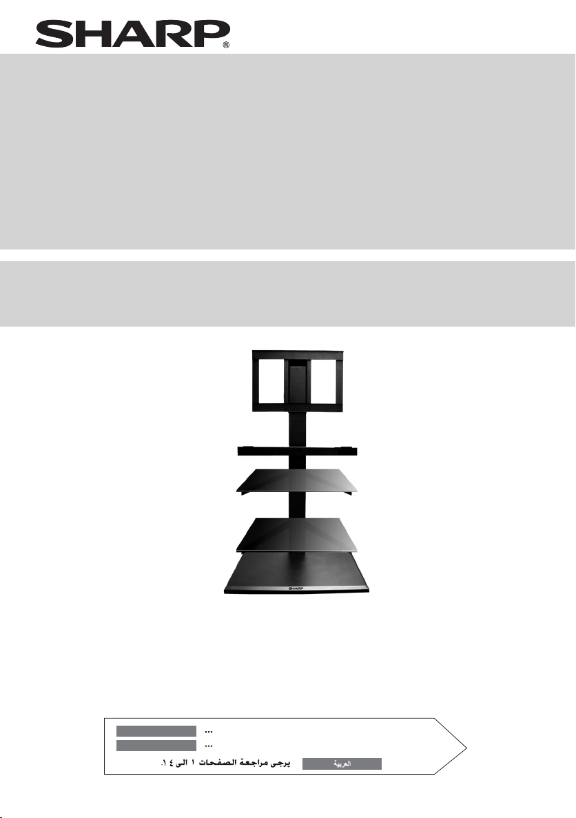
RACK SOPORTE DE PIE
WALL ASIDE STAND
MODELO
MODEL
AN-WS350
AN-WS350R
MANUAL DE MANEJO
OPERATION MANUAL
ESPAÑOL
ENGLISH
Consulte las páginas S-1 a S-14
Please refer to pages E-1 to E-14.
...
Page 2
ENGLISH
Thank you for purchasing this SHARP product. Before using the product, please be sure to
read this operation manual carefully. In particular, be sure to read the section “To Ensure
Safe and Correct Use”. After reading the manual, keep it in a convenient location where it
can be accessed at any time.
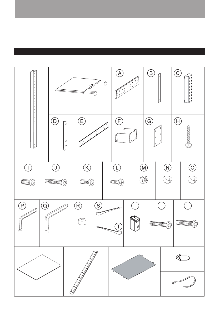
Parts
Please conrm that the following parts are included.
CENTRE BAR x 1
SCREWS
M8 [16mm] x 4
4 mm
ALLEN KEY M6
x 1
LCD TV HOOK
x 2
SCREWS
M6 [35mm] x 6
5 mm
ALLEN KEY M8
x 1
METAL BASE x 1
SOUND BAR
SUPPORT x 1
SCREWS
M6 [16mm] x 53
SOUND BAR
SPACER x 8
SUPPORT (A) x 2
SOUND BAR U
BRACKET x 1
SCREWS
M4 [12 mm] x 6
LEFT x 2
RIGHT x 2
GLASS SHELF
SUPPORT
LCD TV
TV SPACER
SUPPORT (B) x 2
FLANGE
NUT x 20
x 4
LCD TV
SUPPORT
PLATE x 1
SPRING
WASHER
Ø6 x 4
SCREWS
M6 [45mm] x 4
LCD
U BRACKET x 1
SCREWS
M8 [50mm] x 4
SPRING
WASHER
Ø8 x 8
WU V
SCREWS
M8 [45mm] x 4
GLASS x 2
CABLE COVER
x 1
E-1
BACK COVER
x 1
GLASS PROTECTOR x 4
CABLE BAND x 2
Page 3
To Ensure Safe and Correct Use
This operation manual and the product use various displays and labels to ensure safe use. Ignoring these displays
and labels and incorrectly using the product could have results as classied below. Please read the following warning
symbol information before reading the rest of this section, and be sure to strictly observe all instructions.
Warning:
Caution:
Meaning of symbol
Not following these instructions could result in death or serious injury.
Not following these instructions could result in injury or property damage.
The symbol means something that should not be done.
Special Precautions for Safety
Warning:
z Follow the instructions in this manual regarding the installation method and installation orientation. Not following
these instructions could result in injury or damage from falling parts.
z Accurate work is required for the installation work, so please have it done by the dealer or qualied contractor.
z During installation, be careful not to pinch your ngers in the xture, etc.
z Do not apply any other loads to the installation xtures. Doing so could cause the TV to fall causing injury and
damage.
z Do not modify or change the installation parts. Doing so could cause the TV or sound bar system to fall causing
injury and damage.
z Be sure to install the stand on a solid and level oor. When assembling, lay the packing material on the oor to
avoid damage to the oor.
z Do not use a stand if it has sustained any cracks.
z Do not climb on the stand and do not use the stand as a footstool.
z Do not move the stand with the TV attached or with connected equipment inside.
z When using an electric screwdriver, set the torque setting to approximately 2.0 N-m (20 kgf-cm).
z This unit is suitable for SHARP LCD TV with sizes ranging from 32” to 46”.
z Do not use chemicals for cleaning (petrol, paint thinner, etc.). It may damage the cabinet nish. Periodically wipe
it with a soft cloth.
z Do not let children play around the TV stand as this might cause injury or the stand might fall on them.
z Do not step, stand or sit on the glass shelf.
z Maximum load on the glass shelf is 10 kg.
Caution:
Install in a location with low humidity and little dust. Install in a well-ventilated area.
z Do not install the LCD colour TV in a location
with high humidity and much dust. Doing so
could result in re or electric shock.
z Do not place the LCD colour TV where it will
come into contact with oily smoke or steam,
such as near a cooking range or humidier. Doing so could result in re or electric
shock.
z Do not plug the air passage holes in the LCD
colour TV cabinet. Plugging the air passage
holes could trap heat inside the cabinet,
causing a re.
z Do not use the cabinet as follows. Do not
place the cabinet in a place with poor air circulation, such as in a closet or bookcase. Do
not place a drop cloth, etc., on the installed
LCD colour TV.
Please strictly observe the following.
Special skill is required to install the LCD colour TV and Wall Aside Stand, so please have them installed by a
contractor specializing in such installation. The customer should not attempt to install the TV. Sharp shall not be
responsible for improper installation or any accidents, damage, or injury resulting from improper installation.
E-2
Page 4
Assembling the Centre Bar and Metal Base
Note:
Installation of this unit requires 2 or more
persons.
Step 1
Screw the Support Plate (G) to the Metal
Base with 2 pieces of M6 [16mm] screws
(K) rst, using the M6 Allen key (P).
Step 2
Flip the Metal Base upside down. You can
see the “SHARP” logo is facing upwards.
P
K
x 2
G
E-3
Page 5
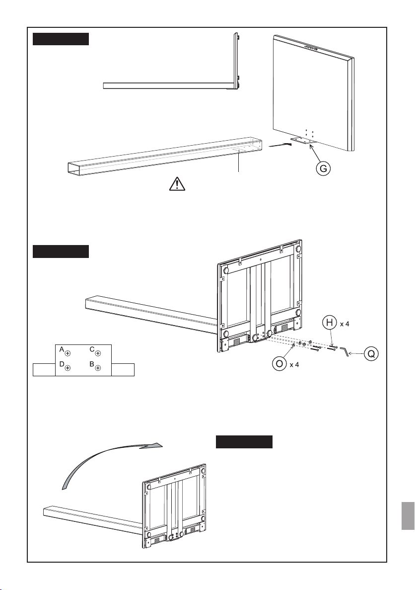
Step 3
Place the Centre Bar next to the Metal Base, on top of the
Support Plate (G).
Side view
Ensure that the specication label
is facing the oor when combining
the Centre Bar and Metal Base.
Step 4
From under the Metal Base, place 4 pieces of M8 [50mm]
screws (H) with Spring Washers Ø8 (O).
The screws should be tightened using Allen key M8 (Q)
according to the sequence A → B → C →D as shown
above.
E-4
Step 5
Slowly lift the xture upwards and let it stand on the
oor.
Page 6

Assembling the Centre Bar and Metal Base (continued)
Step 6
Fasten another 4 pieces of M6 [16 mm]
screws (K) using M6 Allen key (P) to the
Support plate as shown.
Step 7
Before peeling off the masking tape securing the legs, hold the
legs rmly and be careful not to be hit by them. After peeling off
the tape, release the leg slowly until it fully opens out.
Caution:
Be careful not to pinch your ngers
in the xtures.
Specication label
Note:
When pushing the stand against the
wall, the legs will bend inwards.
Assembling the LCD Support Frame
Step 1
Fix the LCD Support Bar (A) with LCD U Bracket (C) using 4
pieces of M6 [16mm] screws (K) and 4 pieces of Flange Nuts
(M). Use M6 Allen key (P) to fasten the screws.
E-5
Note:
This product is designed to be located
against the wall. However, if the user
wishes to locate it further away from
the wall or at the centre of a room,
do ensure that the unit’s legs are fully
opened.
Page 7

Step 2
Slot in the LCD support frame to the Centre Bar as
shown.
Caution:
Do not hold the Support Frame at the
centre while inserting it to the Centre
Bar as this will cause injury.
Step 3
Fix the LCD Support Bar (A) with LCD U Bracket
(C) using 4 pieces of M6 [16mm] screws (K) and 4
pieces of Flange Nuts (M). Use M6 Allen key (P) to
fasten the screws.
Step 4
Fix the LCD Support Bar (B) using 8 pieces of M6
[16mm] screws (K) and 8 pieces of Flange Nuts
(M) as shown. Use M6 Allen key (P) to fasten the
screws.
Step 5
Screw the Support Frame to the Centre Bar using 6
pieces of M6 [16mm] screws (K). Fasten them with
M6 Allen key (P).
E-6
Page 8
Assembling the LCD Support Frame (continued)
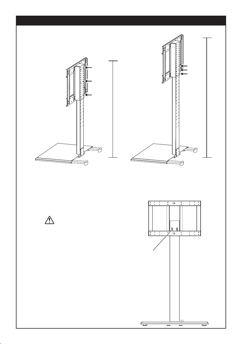
Notes:
z The LCD Support Bar is adjustable to different heights.
Maximum height is 1250 mm. Minimum height is 1030 mm.
z When xing the frame, make sure that all the 6 pieces of M6
[16mm] screws are fastened to it.
Minimum height = 1030 mm
Maximum height = 1250 mm
Caution:
z If adjusting to maximum height, make sure that you
do not exceed the stopper.
z When xing the frame to maximum height, make
sure that all the 6 pieces of M6 [16mm] screws are
fastened to it.
E-7
Stopper
Page 9

Falling prevention (optional)
It is recommended to secure the xture to the
wall with a safety wire or chain before attaching the TV to prevent it from toppling over in
case of earthquake occurrence.
Screw
Washer
Safety wire
(commercially
available)
Assembling the glass shelf
Fix the safety wire or
chain to the wall using
a wall anchor bracket
which is commercially
available.
Step 1
Fix the left (S) and right (T) Glass Shelf Supports to the Centre
Bar using 4 pieces of M6 [16mm] screws (K) as shown. Fasten them with Allen key M6 (P).
Double
sided
tape
Step 2
Remove the transparent glass protective sheet at the bottom
surface of the glass. Top surface has a label afxed on it.
Peel off the separator of the double sided tape on the Glass
Protectors. Slot in 2 pieces of Glass Protector at the corners
of the glass as shown below.
Double sided tape
Glass protective
Step 3
Peel off the separator of the double sided tape on the
left and right Glass Shelf Supports.
sheet
E-8
Label
Top surface
surface
Page 10

Assembling the glass shelf (continued)
Glass protector
guide
Hole
Step 4
Place the glass on the Glass Shelf Supports as shown.
Make sure all the Glass Protector guides are inserted
perfectly into the holes of the left and right Glass Shelf
Supports.
Notes:
z The glass is made of reinforced glass, but dropping
pointed objects on it or strongly hitting the surface may
cause it to break.
z The glass shelf is not fastened to the unit. Avoid han-
dling the glass when transporting the unit, otherwise it
may fall off and there is a risk of damage and injury.
Label
Assembling the Sound bar Support (optional)
You can include your Sound bar system to this unit to enhance the sound of your LCD TV.
Step 1
Fix the wall mount angle (comes with Sound bar
unit) to the Sound bar Support (E) using 4 pieces
of M4 [12mm] screws (L). Fasten them with a “+”
screw driver.
WALL MOUNT ANGLE
(not supplied)
Step 2
Screw the Sound bar Support (E) to the Sound bar U Bracket
(F) using 4 pieces of M6 [35mm] screws (J) with 4 pieces of
Flange Nuts (M). Insert 8 pieces of Sound bar Spacers (R) as
shown below. Fasten them with M6 Allen key (P).
Notes:
You can omit the Sound bar Spacers (R) if you like but when
you do this, make sure that the screw type is changed from
M6 [35mm] (J) to M6 [16mm] (K)
R
E-9
Page 11

Assembling the Sound bar Support (optional) (continued)
Step 3
Step 3
Fasten the xture to the Centre Bar using 4 pieces
of M6 [16mm] screws (K) with M6 Allen key (P).
K
Step 5
Fasten 2 pieces of M4 [12 mm] screws (L) to the
Sound bar Support as shown using a “+” screw
driver.
Step 4
Hook the sound bar to the Sound bar Support at
both sides.
x 4
P
Step 6
Use the supplied Cable Band to tie the AC adaptor
of the Sound bar to the Sound bar Support.
L
x 2
AC adaptor
E-10
Page 12

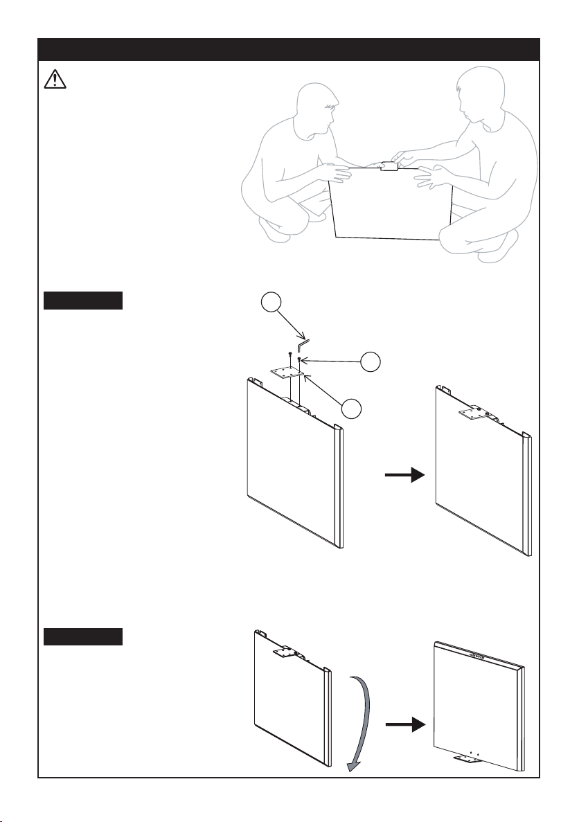
Attaching the LCD TV Hook to the LCD TV
LCD TV
Max. = 400 mm
Max. = 400 mm
Note:
The screw holes distance on the
TV for the LCD TV hook should
not exceed 400 mm by 400 mm.
If using a Blu-Ray LCD TV (Optional)
Use below TV Spacer to x the LCD TV hooks.
For upperside TV Spacer xing:
turn the spacer guide downwards.
Spacer guide
D
x 4
U
Blu-Ray
Compartment
x 2
Step 1
Screw the LCD TV hooks to the
back of the LCD TV using 4 pieces
of M6 [16 mm] screws (K) with 4
pieces of Spring Washers Ø6 (N)
or 4 pieces of M8 [16 mm] screws
(I) with 4 pieces of Spring Washers
Ø8 (O), depending on the TV nut
size as shown. Fasten them using
M6 Allen key (P) or M8 Allen key
(Q).
Caution:
Sharp shall not bear any responsibility
for damages, etc., caused by the LCD
colour TV falling due to insufcient installation strength or improper installation.
Screw the LCD TV hooks to the
back of the LCD TV using 4 pieces
of M6 [45mm] screws (V) with 4
pieces of Spring Washers Ø6 (N) or
4 pieces of M8 [45mm] screws (W)
with 4 pieces of Spring Washers Ø8
N
(O), depending on the TV nut size
x 4
as shown. Fasten them using M6
Allen keys (P) or M8 Allen keys (Q).
For lowerside TV Spacer xing:
turn the spacer guide upwards.
E-11
P
x 4
V
Page 13

Attaching the LCD TV Hook to the LCD TV (continued)
Step 2
Hook the TV to the LCD Support as shown.
Note:
LCD colour TVs have a viewing angle (range in which
the image can be viewed correctly). The best viewing
position is from directly in front of the screen. Determine the TV installation location after taking into consideration the viewing posture, line of sight, and the
visual and aural ranges.
Fasten 2 pieces of M6 [35 mm] screws (J) as
shown to x the TV position to prevent it from sliding sideways. Use the M6 Allen key (P) to fasten
them.
Wire arrangement
You can arrange and hide the cables at the back by using the supplied Cable Cover.
Fix the Cable Cover to the Centre Bar using 3 pieces of M6 [16 mm]
screws (K) as shown. Fasten them using M6 Allen key (P).
Lift up the Cable Cover and insert all the cables neatly as shown.
Step 3
E-12
Page 14
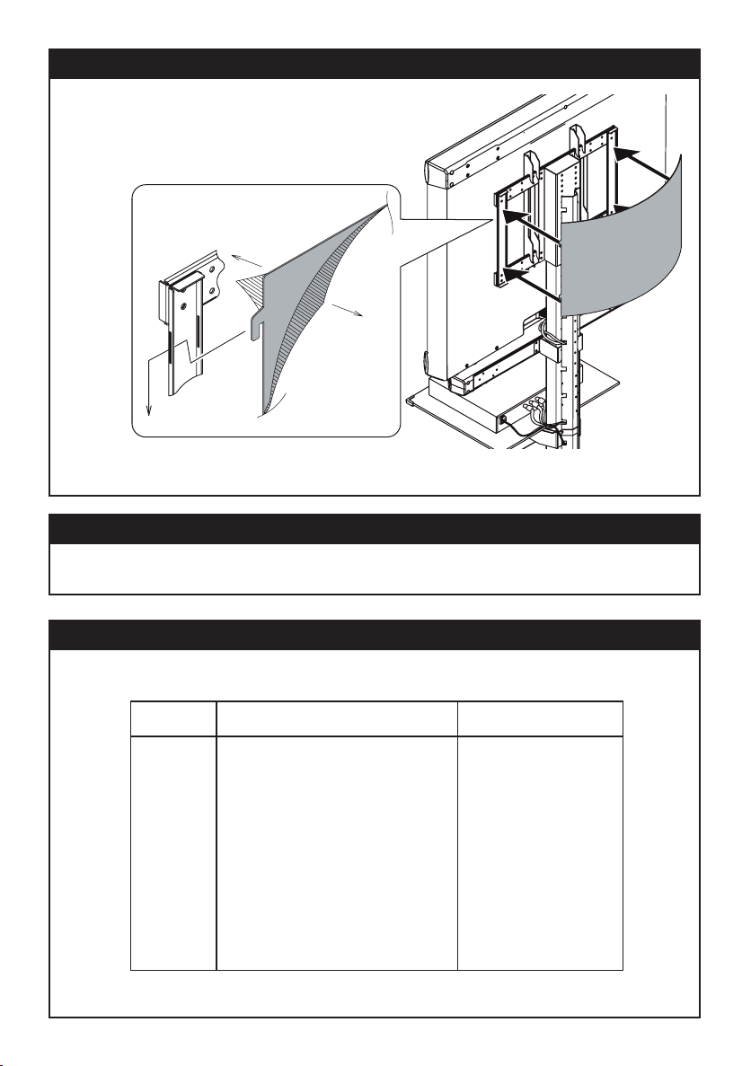
Attaching the Back Cover
You can cover the wires at the back by attaching the Back Cover.
Slot in the Back Cover hooks (4 portions) into the LCD Support as
shown.
Peel off the protection sheet at both
sides of the Back Cover.
Cleaning the stand
To remove any stain from the stand, wipe the surface with soft cloth. Do not use chemicals as it may damage the
surface nish.
Specied products
The following products are subject to change without notice.
Certain models may not be available in certain regions.
SHARP LCD colour TV SHARP Sound bar system
46LE700E
46LE600E
46HD1E
46DH77E
46XL2E
46D65E/DH65E
AN-WS350
AN-WS350R
There may be other models that can be used with this stand. For these models, refer to their operating instructions,
or the supplied leaet to verify that the stand can be used.
46X20E
46X8E
42DH77E
42XL2E
42X20E
42SB55E
42SH7E
40LE700E
40LE600E
37XL8E
37D65E/DH65E
37X20E
37D44E
32LE700E
32LE600E
32DH77E
32SH7E/S7E
32XL8E
32D65E/DH65E
32X20E
32RD8E
32SB25E
32DH57D
32D44E
32A47E
HT-SB200
HT-SB300
HT-SB400
HT-SB500
E-13
Page 15

Specication
(e)
100 mm
500 mm
(b) (c) (d)
Front view
(a)
1021.7 mm
380 mm
470 mm 176 mm 675 mm
Side view
Dimensions
Weight
Stand maximum
load
Glass shelf
maximum load
a
1021.7 mm (40 - 7/32”)
b
675 mm (26 - 9/16”)
c
470 mm (18 - 1/2”)
d
176 mm (6 - 15/16”)
e
100 mm (3 - 15/16”)
27 kg (59.52 lbs.)
60 kg (132.3 lbs.)
10 kg (22.05 lbs.)
E-14
 Loading...