


Wireless LAN PC Card
AN-WC11B
OPERATION MANUAL
Make sure to read this manual thoroughly
in order to correctly use this product.
For
Windows

1. Contents
1. Contents ......................................................................................................... 2
2. IMPORTANT SAFEGUARDS ..........................................................................3
3. Introduction ................................................................................................... 5
4. System Requirements....................................................................................6
5. Parts Names and Functions ..........................................................................6
6. What you can do with the Wireless LAN PC Card .......................................7
6.1 Project Images on a Large Screen via a Wireless Connection .............................................................................. 7
6.2 Exchange Data via a Wireless Connection ............................................................................................................ 7
6.3 Connect to the Internet via a Wireless Connection ................................................................................................ 7
7. Configuring and Checking the Wireless LAN PC Card ...............................8
8. Installing......................................................................................................... 9
8.1 Install Procedure for Windows 98/Me/2000/XP....................................................................................................... 9
8.2 Removing the Software......................................................................................................................................... 16
9. Transmission via a Wireless LAN................................................................17
9.1 Transmitting via a Wireless LAN PC Card............................................................................................................ 17
10. Configuration Utility...................................................................................20
10.1 “Status” Tab ....................................................................................................................................................... 21
10.2 “Configuration” Tab ............................................................................................................................................ 22
10.3 “Encryption” Tab ................................................................................................................................................ 25
10.4 “About” Tab ........................................................................................................................................................ 27
11. Troubleshooting..........................................................................................28
In Windows 98:............................................................................................................................................................ 28
In Windows 2000:........................................................................................................................................................ 28
Unable to Communicate ............................................................................................................................................. 28
Slow Transmit Rate ..................................................................................................................................................... 29
When the Wireless LAN Card does not work .............................................................................................................. 29
12. Glossary ......................................................................................................32
13. Wireless LAN PC Card Specifications ......................................................34
14. Index ............................................................................................................35
For SHARP Assistance....................................................................................36
-2
2. IMPORTANT SAFEGUARDS
WARNING
Do not use this product in facilities or near equipment that concerns human life, such as
medical, nuclear, aerospace or transportation equipment or facilities, as well as equipment or facilities in which high reliability is necessary.
Do not use near people with pacemakers as this product may cause electromagnetic
interference.
Do not use this product near medical equipment as this product may cause electromagnetic interference.
-3
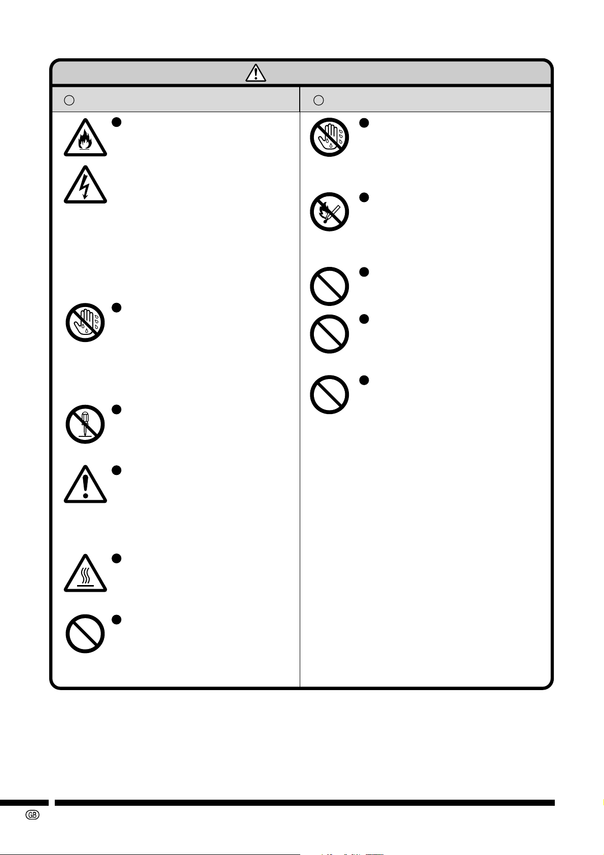
WARNING
Precautions for use
Should smoke, strange odors, or
other abnormalities occur, turn
off the computer that has the
Wireless LAN PC Card installed
and the wireless access point,
and remove the Wireless LAN
PC Card. After making sure that
smoke has stopped, contact your
nearest Sharp Authorized
Projector Dealer or Service
Center. Continued use creates
the danger of fire, electric shock
or malfunction.
Make sure that water or other
liquids do not wet the Wireless
LAN PC Card. Also, do not touch
the Wireless LAN PC Card with
wet hands. Doing so creates the
danger of fire, electric shock or
malfunction.
Do not attempt to disassemble,
modify or repair the card by
yourself. Doing so may cause
malfunction.
Before installing or removing the
Wireless LAN PC Card, make
sure to touch any metallic object
such as a faucet or doorknob, to
discharge any static electricity in
your body.
Locations for use
Do not use in wet places or
places with high humidity, and
places where dew can easily
form. Doing so may lead to short
circuit or malfunction.
Do not use in places exposed to
direct sunlight, near fire or heat
sources. The temperature might
rise and lead to fire and
damage.
Do not use in places exposed to
large amounts of dust, as it may
cause malfunction.
Do not use in places where the
card can be exposed to impact
or vibration. Doing so may lead
to malfunction and damage.
Do not use in places exposed to
strong magnetic fields, static
electricity and places where
signal interruption may occur
(near a microwave oven etc.).
Doing so may lead to
malfunction or damage.
-4
The Wireless LAN PC Card may
become hot after long hours of
usage. Take care when removing
the card so as to avoid burns.
Make sure that chemical agents
or harmful gases do not come in
contact with the card. This may
corrode the card or cause harm
to humans.

3. Introduction
Thank you for purchasing of the SHARP Wireless LAN PC Card. This manual will assist you with
the installation procedure.
• The CD-ROM contains drivers and the “Configuration Utility” program that is used for managing
the Wireless LAN PC Card and establishing a wireless connection with your Local Area Network.
• This manual assumes that you are familiar with Windows and mouse operations. If not, refer to the appropriate documentation that comes with the Windows operating system.
• This operation manual is based on the Windows XP Classic View.
When using Windows XP, please change to the Classic View. To change to the Classic View, make the
settings in “Control Panel” on the “Start” menu. For more information about the settings, please refer to the
Windows XP user’s guide.
The specifications of this software are subject to change without prior notice.
Copyright
No part of this manual may be reproduced or transmitted in any form or by any means (electronic, mechanical,
photocopying, recording, or otherwise), or for any purpose, without the express written permission of the
● Microsoft, Windows are either registered trademarks or trademarks of Microsoft Corporation in the United
States and/or other countries.
● Other product and company names mentioned herein may be the registered trademarks or the trademarks
of their respective owners.
● The explanations in this manual may vary depending on the type of computer you are using. Also, operations may be slower, depending on the operating environment and processing capability of your computer.
author.
About this manual
• This manual may not be transferred wholly or in part any form whatsoever without prior written permission.
• This manual is subject to change without prior notice.
• The copyright of this manual is under jurisdiction of SHARP.
About the Wireless LAN PC Card
• SHARP assumes no responsibility for damages incurred from the loss of business profits or business opportunities due to external causes such as Wireless LAN PC Card failure, malfunction, problems or power
blackouts.
• SHARP assumes no responsibility for damages due to transmission misuse.
• SHARP assumes no responsibility for transmission data leakage.
-5
4. System Requirements
CAUTION
The following hardware or software is required when using this software.
• Computer: A personal computer capable of operating with any of the
• Basic Operating System: Microsoft Windows 98, 98SE, Me, 2000 Professional, XP
• CPU: 500MHz Pentium III processor or higher recommended
• Display: A 1,024 × 768 dot display capable of 65,536 colors or more
• Memory: 64 MB or more (Windows 98, 98SE, Me)
• Hard Disk Space: 50 MB or more of free hard disk space
• Interface: PC card slot (PCMCIA TYPE II)
• CD-ROM Drive
• Others: Internet Explorer 4.01 or later
• Wireless LAN PC Card: Supports the “AN-WC11B”
operating systems mentioned below.
Home Edition, XP Professional Edition. (Japanese and
English versions)
recommended
96 MB or more (Windows 2000 Professional)
160 MB or more (Windows XP Home Edition, XP Professional Edition)
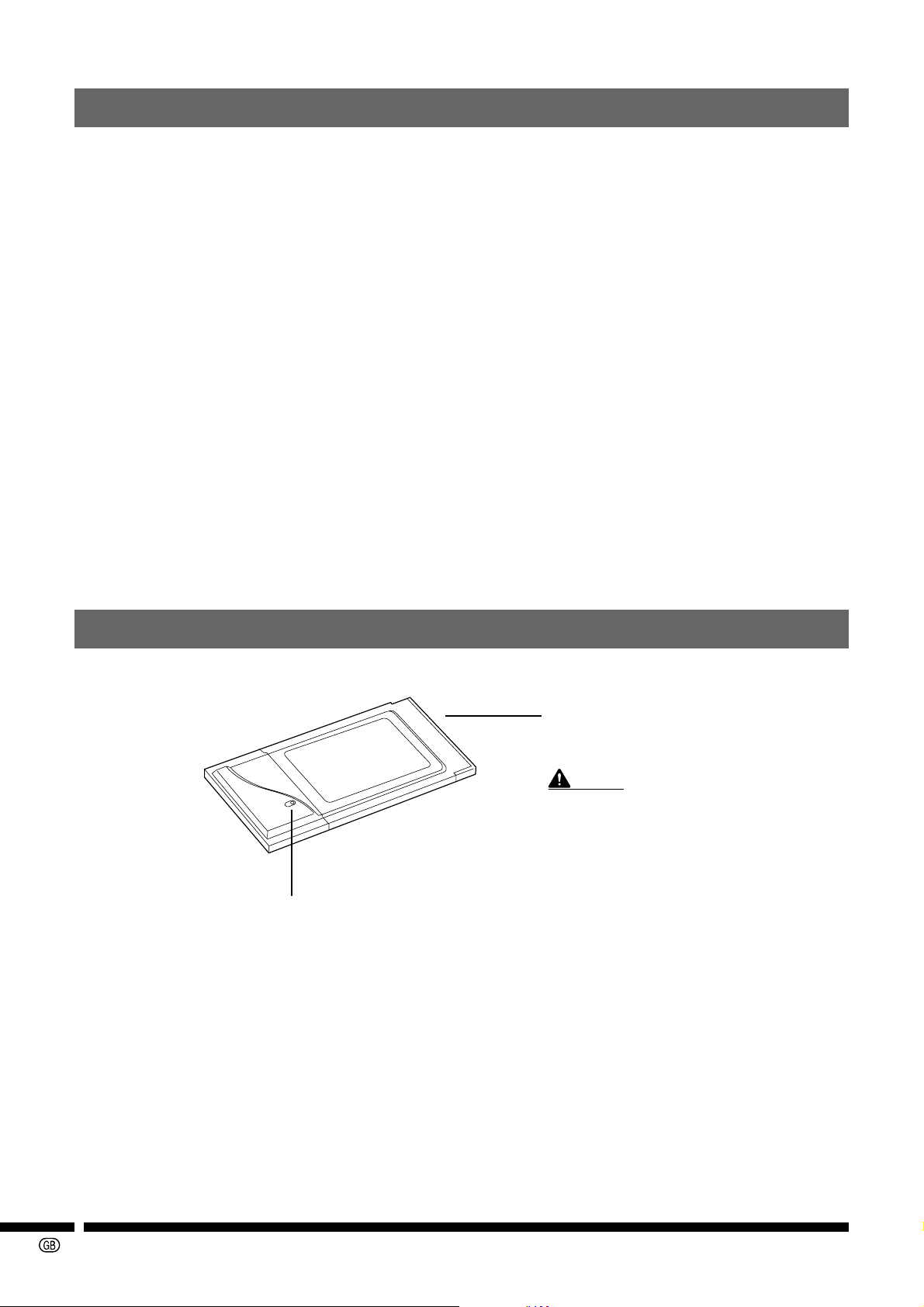
5. Parts Names and Functions
Face of Card
LINK indicator
This indicates the Wireless LAN PC Card’s status.
The indicator is lit: wireless transmission is ready.
The indicator is blinking: wireless transmission is not possible.
The indicator is off: The Wireless LAN PC Card cannot be used.
PCMCIA connector
Connector for PC card slot on computers or
wireless LAN access points.
Do not touch the PCMCIA connector as this
may cause damage to the card.
-6
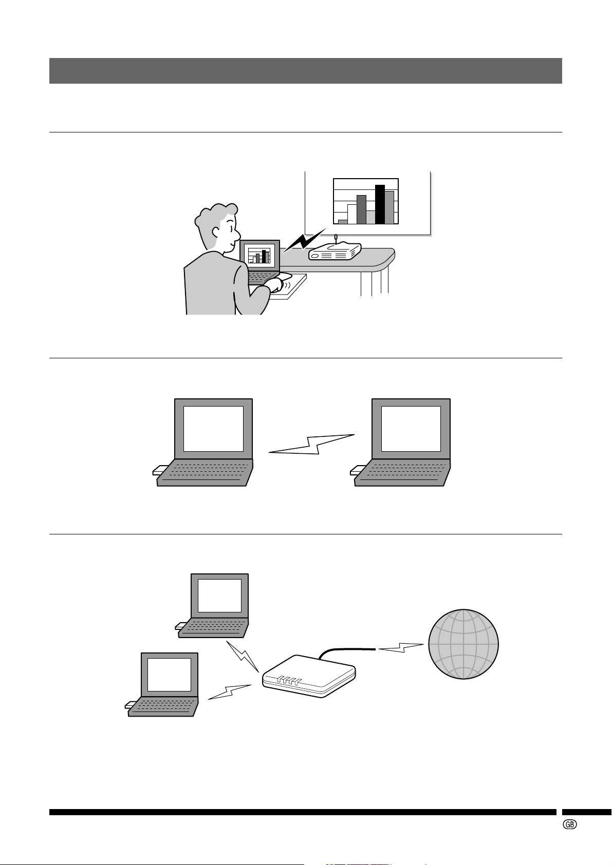
6. What you can do with the Wireless LAN PC Card
You can do the following using the Wireless LAN PC Card.
6.1 Project Images on a Large Screen via a Wireless Connection
If your projector supports the wireless projection function, you can project on large screens your
PC’s display without connecting the PC and projector.
6.2 Exchange Data via a Wireless Connection
You can exchange the data without using wires or cables.
PCs installed with Wireless LAN PC Cards can exchange data and share printers. (Peer-to-Peer)
6.3 Connect to the Internet via a Wireless Connection
If you use a commercially available wireless LAN access point, you can connect to the Internet
even if your wired LAN and computer are in different places. (Access Point)
Access Point
Internet
-7
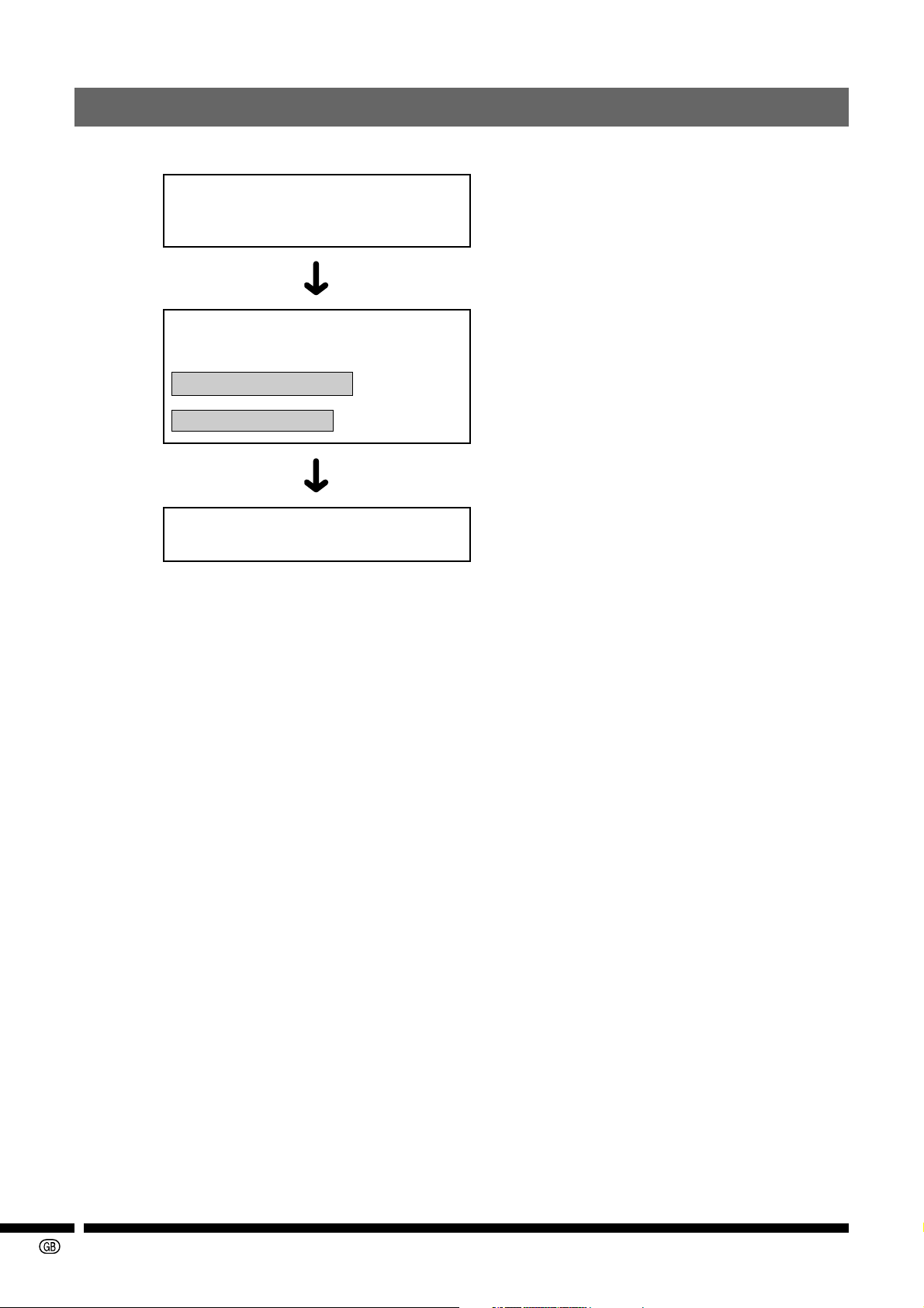
7. Configuring and Checking the Wireless LAN PC Card
The following describes the configuration and checking of the Wireless LAN PC Card.
Installing the software
Detecting the Wireless LAN PC Card
Configurations for connecting to the
Network
Automatic configuration
Manual configuration
Configuring the transmission mode or
operations
........ “8. Installing” on page 9.
........
See the “Wireless Reality Soft OPERATION
MANUAL”.
........
“9. Transmission via a Wireless LAN” on page 17.
........ “10. Configuration Utility” on page 20.
-8
8. Installing
8.1 Install Procedure for Windows 98/Me/2000/XP
Install this software using the setup program included on the CD-ROM.
CAUTION
• Make sure to consult your Network Administrator when installing this software on a computer connected to a network.
• Before touching the Wireless LAN PC Card, make sure to touch any metallic object such as a
faucet or doorknob to discharge any static electricity in your body.
Before installing
• If there are any other 11 Mbps (IEEE802.11b std) wireless LAN card drivers already installed
on your computer, make sure to uninstall them before performing the procedure below.
• Do not insert the wireless LAN PC card into the PC card slot on the computer until indicated
by the instructions on the screen.
1
Make sure that the computer you are using supports this software.
For details, see “4. System Requirements” on page 6.
2
Turn on the computer.
• If your operating system is Windows 2000 or Windows XP, log on using an account that has
Administrators permission.
3
Make sure to close all other applications before installing.
4
Make sure that there is no Wireless LAN PC Card inserted yet.
5
Insert the included CD-ROM into the computer’s CD-ROM drive.
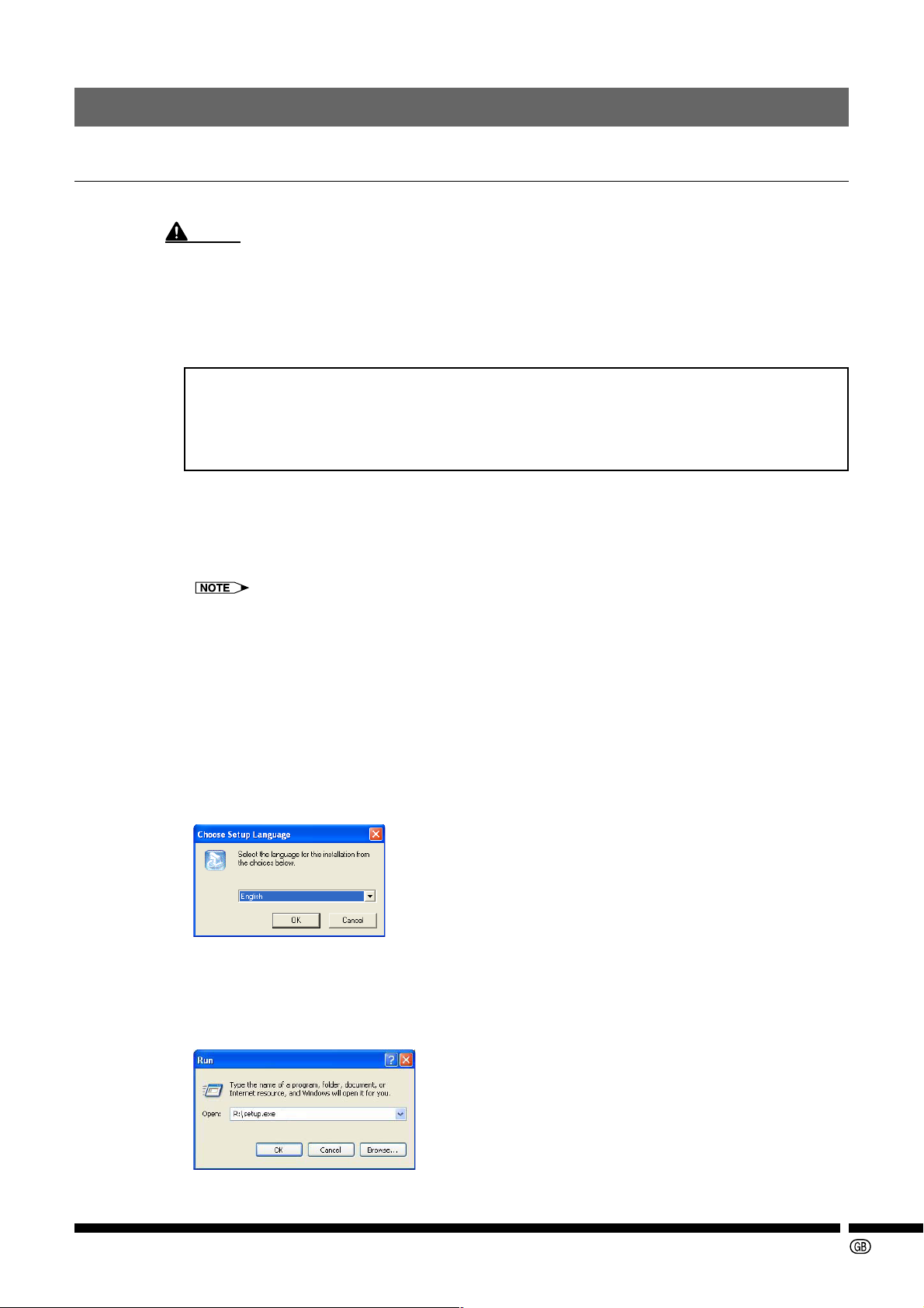
6
Select “English”, and click “OK” when the “Choose Setup Language” dialog box
is displayed.
If the “Choose Setup Language” dialog box is not displayed:
1 Click the “Start” button, and then “Run”.
2 Enter “R:\setup.exe” and click “OK”.
(Enter the CD-ROM drive letter if it is different from “R”.)
-9
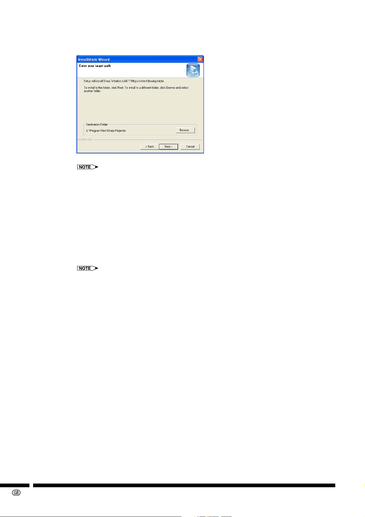
7
Select the install destination on the “Choose Destination Location” dialog box,
and then click “Next>”.
• Normally, it is not necessary to change the settings providing there are no problems.
8
Click “Next>”.
Installation starts. When the “Digital Signature Not Found” dialog box or the “Hardware Installation” dialog box is displayed, click “Yes” or “Continue Anyway”.
When installation has finished, “InstallShield Wizard Complete” dialog box is displayed.
Depending on the operating system, the “InstallShield Wizard Complete” dialog box may not
be displayed. In this case, restart your computer.
9
Select “Yes, I want to restart my computer now.”, and then click “Finish” to restart the computer.
If your operating system is Windows 2000 or Windows XP, the “InstallShield Wizard Complete”
dialog box may not be displayed. In this case, restart your computer. After restarting your computer, log on with the same log-on name you used in step 2.
The following procedures vary depending on the operating system you are using.
• Windows 98/Me ....................page 11
• Windows 2000 ......................page 12
• Windows XP .........................page 13
-10
Using Windows 98/Me
10
Insert the Wireless LAN PC Card into the PC card slot.
CAUTION
• Do not insert the Wireless LAN PC Card until the computer is fully loaded.
• Make sure to insert the Wireless LAN PC Card with the LINK indicator facing upwards. If you
force the card into the slot in the wrong direction, it may damage the connector and communication will not be possible.
The location of the PC card slot may vary depending on your computer. For details, refer to the
documentation that comes with your computer.
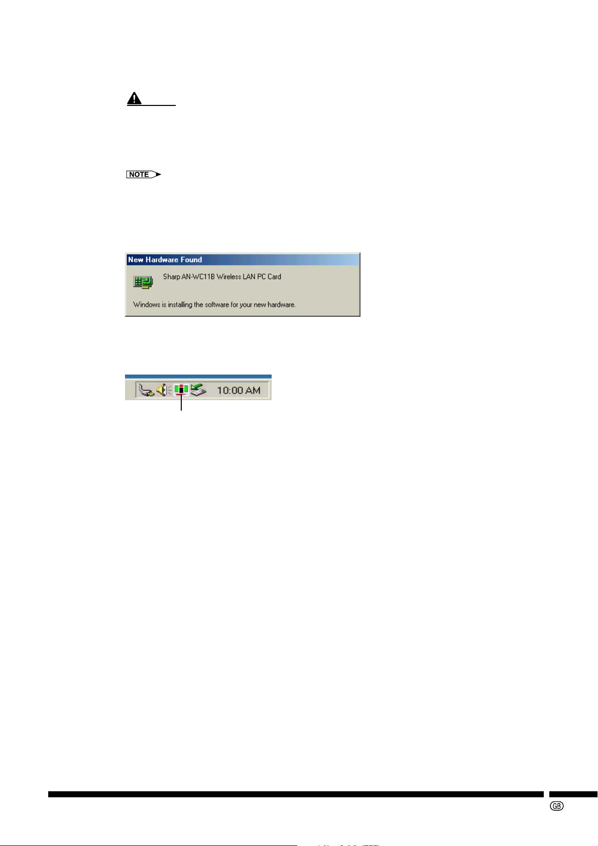
11
Wait until the screen below is displayed and the Wireless LAN PC Card driver is
installed.
• When the “Digital Signature Not Found” dialog box is displayed, click “Yes”.
■ Check if the “Configuration Utility for Wireless LAN” is displayed on the task
tray
Configuration Utility for Wireless LAN icon
(The color of the icon varies according to the signal status.)
If this icon is not displayed on the status bar, the driver is not properly installed.
See “If the unit does not function properly” on page 14 to uninstall and then reinstall the driver.
12
From the “Start” menu, click “Settings”, “Control Panel”, and then double click
“PC Card”.
13
Check if there is a “Sharp AN-WC11B Wireless LAN PC Card” in one of the sockets.
If “Sharp AN-WC11B Wireless LAN PC Card” is displayed, the card has been correctly detected.
14
Double click “Control Panel”, and then click “System”.
15
Click the “Device Manager” tab, and then double click “Network adapters”.
If the “Sharp AN-WC11B Wireless LAN PC Card” is displayed, installation is completed.
If there is a yellow “ ? ” or “ ! ” mark next to the “Sharp AN-WC11B Wireless LAN PC Card”
icon, then installation has failed. Refer to “11. Troubleshooting” on page 28.
-11

Using Windows 2000
10
Insert the Wireless LAN PC Card into the PC card slot.
CAUTION
• Do not insert the Wireless LAN PC Card until the computer is fully loaded.
• Make sure to insert the wireless LAN PC Card with the LINK indicator facing upwards. If you
force the card into the slot in the wrong direction, it may damage the connector and communication will not be possible.
The location of the PC card slot may vary depending on your computer. For details, refer to the
documentation that comes with your computer.
11
Follow the instructions displayed on the screen below.
• When the “Digital Signature Not Found” dialog box is displayed, click “Ye s ”.
■ Check if the “Configuration Utility for Wireless LAN” is displayed on the task
tray
Configuration Utility for Wireless LAN icon
(The color of the icon varies according to the signal status.)
If this icon is not displayed on the status bar, the driver is not properly installed.
See “If the unit does not function properly” on page 14 to uninstall and then reinstall the driver.
12
From the “Start” menu, click “Settings”, and then “Control Panel”.
13
Double click the “System” icon.
14
Click the “Hardware” tab, and then “Device Manager”.
15
Double click “Network adapters”.
If the “Sharp AN-WC11B Wireless LAN PC Card” is displayed, installation is completed.
If there is a yellow “ ? ” or “ ! ” mark next to the “Sharp AN-WC11B Wireless LAN PC Card”
icon, then installation has failed. Refer to “11. Troubleshooting” on page 28.
-12

Using Windows XP
10
Insert the Wireless LAN PC Card into the PC card slot.
CAUTION
• Do not insert the Wireless LAN PC Card until the computer is fully loaded.
• Make sure to insert the wireless LAN PC Card with the LINK indicator facing upwards. If you
force the card into the slot in the wrong direction, it may damage the connector and communication will not be possible.
The location of the PC card slot may vary depending on your computer. For details, refer to the
documentation that comes with your computer.
11
Follow the instructions displayed on the screen below.
When the “Hardware Installation” dialog is displayed, click “Continue Anyway”.
■ Check if the “Configuration Utility for Wireless LAN” is displayed on the task
tray
Configuration Utility for Wireless LAN icon
(The color of the icon varies according to the signal status.)
If this icon is not displayed on the status bar, the driver is not properly installed.
See “If the unit does not function properly” on page 14 to uninstall and then reinstall the driver.
-13

When the LINK indicator on the Wireless LAN PC Card is lit:
1 Double click the wireless network connection icon ( ) in the status bar.
2 Select “SHARP_PRJ” and click “Connect”.
Make sure that the icon is green ( ). The LINK indicator lights up.
12
From the “Start” button, click “Control Panel”.
13
On the upper left hand cover, click “Switch to Classic View”, and then click “System” on the right.
14
Click the “Hardware” tab, and then click “Device Manager”.
15
Double click “Network adapters”.
If the “Sharp AN-WC11B Wireless LAN PC Card” is displayed, installation is completed.
If there is a yellow “ ? ” or “ ! ” mark next to the “Sharp 11 Mbps Wireless LAN PC Card” icon,
then installation has failed. Refer to “11. Troubleshooting” on page 28.
If the unit does not function properly:
“!”, “?” or “×” is displayed on the “Sharp AN-WC11B Wireless LAN PC Card” icon indicates that the
Wireless LAN PC Card driver is not functioning.
An error occurred
The following can be probable causes for the error:
• The “Sharp AN-WC11B Wireless LAN PC Card” is not properly installed.
• Another wireless LAN PC card is already installed.
• Driver or hardware conflict.
If any of these errors occur, uninstall the “Sharp AN-WC11B Wireless LAN PC Card” and then
reinstall it again. (Refer to page 15.)
If there is another wireless LAN PC card already installed, uninstall it first before installing the
Sharp AN-WC11B Wireless LAN PC Card.
To uninstall other wireless LAN PC cards from your computer, refer to the documentation of
the respective wireless LAN PC card.
-14

■ Reinstalling the “Sharp AN-WC11B Wireless LAN PC Card” driver
The AN-WC11B Wireless LAN PC Card driver should be uninstalled before reinstalling.
1
Click the “Start” menu, “Settings”, and then “Control Panel”.
2
Double click “System”, and then select the “Hardware” tab.
3
Click “Device Manager” , and then [+] in “Network adapters”.
4
Select the “Sharp AN-WC11B Wireless LAN PC Card”, and then click “Uninstall”.
5
Click “OK”.
6
Make sure that the PC card adapter icon has disappeared from the status bar, and
remove the “Sharp AN-WC11B Wireless LAN PC Card” from the computer’s PC
card slot.
Before removing the card, make sure that the two icons have disappeared.
• Depending on the operating system, the LINK indicator on the Wireless LAN PC Card may
stay lit. This does not indicate a malfunction.
For information about how to remove the PC card, refer to the documentation that comes with
your computer.
-15

7
Uninstall the AN-WC11B Wireless LAN PC Card “Configuration Utility” software.
For more information about uninstall, refer to “8.2 Removing the Software” on page 16.
8
Restart the computer.
9
Install the AN-WC11B Wireless LAN PC Card driver.
For more information about installation, refer to “8. Installing” on page 9.
8.2 Removing the Software
If you want to uninstall Wireless LAN PC Card driver, please follow the steps as below.
1
Close all applications that are currently running.
2
Remove the Wireless LAN PC Card from the computer.
3
Click the “Start” menu, “Settings”, and then “Control Panel”.
4
Click the “Add or Remove Programs” icon.
5
Select “Sharp Wireless LAN PC Card”, and then click “Change/Remove”.
-16
6
Follow the instruction on the screen.

9. Transmission via a Wireless LAN
In this section, communication settings between computers that have Wireless LAN PC cards
installed and file or printer sharing is explained.
9.1 Transmitting via a Wireless LAN PC Card
You can exchange data between the computer and projector when both have Wireless LAN PC
cards installed, or share a printer connected to a computer with the Wireless LAN PC Card installed. When you want to set computers to communicate via Wireless LAN PC cards using the
following settings, you can also communicate between the cards as well. Make sure that the all the
computers that will be transmitting data and the projectors have been set the same.
• Configure an IP address, Subnet mask and Gateway.
• Configure to “Peer-to-Peer” as the “Network Type”.
• Set the each transmission channel to same channel.
• Configure the same name for the network name (SS ID or ESS ID).
• Configure the same wireless network key or WEP key, when using “Encryption (WEP security)”.
• When sending data between Wireless LAN PC cards, make sure to set channel 5 or over as inter-
ference may occur if another Wireless LAN PC cards is used nearby. For example, if Wireless LAN
PC cards are communicating already on channel 1, then set channel 6.
• If no Wireless LAN PC Card is used, you do not have to change the default settings of the transmission channel.
• Make sure to consult your Network Administrator should any network related problems occur.
The configuration varies depending on your operating system. In this operation manual, Windows
XP Classic View is used as example.
When using Windows XP
Follow the procedure below to transmit using the 802.11 AdHoc mode.
1
From the “Start” menu, click “Settings”, and then click “Control Panel”. Double
click “Network Connections”, and then double click “Wireless Network Connection”.
2
Click the “Advanced” button, and then click the “General” tab.
3
Select “Internet Protocol (TCP/IP)”, and then click the “Properties”.
4
Click “Use the following IP address”, then enter the values of “IP address”, “Subnet
mask” and “Default gateway”, and then click “OK”.
-17

Enter the following values as an example.
IP address
Enter 192.168.150.151.
Subnet mask
Enter 255.255.255.0.
Default gateway
Enter 192.168.150.1.
5
Click “Close” to close “Wireless Network Connection Properties”.
6
Click at the above of the display to close “Wireless Network Connection Status”.
7
Click on the task bar, then click “Advanced Configuration…”.
If is not on the task bar, it will appear by double-clicking “Sharp W-LAN Settings” on
“Control Panel”.
8
Click the “Configuration” tab.
-18

9
Enter the configuration name in “Profile Name”.
Enter “802.11 AdHoc mode” here as an example.
10
Select “Peer-to-Peer” in “Network Type”.
• When connecting to the Network using an Access Point, change the “Network Type” to “Ac-
cess Point”.
• When changing a channel, use '" to select the channel.
• When changing the SS ID, enter SS ID in the “SS ID” field.
• When setting the encryption key, refer to “10.3 Encryption Tab” on page 25.
11
Click “Apply”.
12
Click on the upper right of the screen to close the “Configuration Utility” dialog
box.
To communicate again with the access point:
When setting in the following way, you will be able to communicate again with the access point.
• Check the Windows Network Settings. (For more information about the settings, please
refer to the Windows user’s guide.)
• In the “Configuration” tab (step 10 above), select “Access Point” in “Network Type”.
-19

10. Configuration Utility
• When using together with the projector PG-M25X, the software included with the projector (such as
“Network Selector”) will automatically make all the appropriate settings. Therefore, it is not necessary to make any settings in this utility program.
After the installation of the “Wireless LAN PC Card Configuration Utility”, the “Configuration Utility”
icon appears in the task bar.
The “Configuration Utility” icon
The color behind the icon indicates the transmission status.
Due to weak signals, transmission may not be possible.
Transmission Speed becomes slower, even if transmission has been enabled.
Transmission can be done normally.
You can also view the status of the transmission by placing the cursor over the “Configuration
Utility” icon.
-20

10.1 “Status” Tab
The “Status” tab displays information on the status of your communications with the wireless LAN.
The fields in this menu provide the following information:
• State: Shows the association state of your computer with the wireless LAN.
When operating in “Access Point”, this field shows the MAC address of
the Access Point with which you are communicating. When operating in
“Peer-to-Peer”, this field shows the virtual MAC address used by computers connected to the AdHoc network.
• Current Tx Rate: Shows the highest transmit rate of the current association.
• Current Channel: Shows the channel on which the connection is made. In “Access Point”,
this number changes as the transmitter scans the available channels.
• Rescan: You can click the “Rescan” button to force the transmitter to rescan all
available channels. If your “Link Quality” or “Signal Strength” is “Poor”,
rescanning can be used to push the transmitter away from a weak
Access Point and search for a better link with another Access Point.
• Throughput: Shows the short term transmission and reception throughput in bytes/
second, and is continuously updated.
• Link Quality: The “Link Quality” is displayed as a value and a graph.
• Signal Strength: The “Signal Strength” is displayed as a value and a graph.
• Disable/Enable Radio: Switches On or Off the Power Save Mode when pressed.
When activated, the Power Save Mode reduces the amount of energy
consumed.
Disable Radio
The Power Save Mode is inactive.
Enable Radio
The Power Save Mode is active.
The transmission speed via a wireless LAN is reduced, when the Power
Save Mode is enabled.
-21

10.2 “Configuration” Tab
In the “Configuration” tab, you can configure the Wireless LAN PC Card.
After installing the “Configuration Utility”, and after the computer has been started, this dialog box
will be displayed.
■ Setting the Profile
Profiles are files that have various settings of the Wireless LAN PC Card. If the settings that you
normally use are saved every time as profiles, you can easily modify all at once just by selecting a
profile. Click the pull down button on the right of the “Profile Name” box, to see the profiles that can
be selected.
Selecting and modifying a profile at once
1
Click the pull down button on the right of the “Profile Name” box.
The profiles that can be selected are displayed.
2
Select the profile from the list and click “Apply”.
The settings in the profile are modified at once.
Right after installation, the profile is only “Default.”
Creating a new profile
1
Change the values for the new profile.
2
Click next to the “Profile Name” box, and enter the profile name.
3
Click “Apply”.
The new profile is saved under the entered name.
Modifying the saved profile
1
Click the pull down button on the right of the “Profile Name” box.
Profiles that can be selected are displayed in a list.
-22
2
Select the profile from the list.
The set values are temporarily displayed.
3
Change the set value and click “Apply”.
The current settings are overwritten.
You can also modify a “Default” profile.

■ Setting the SS ID
The SS ID is used by Access Points and Wireless LAN PC Cards to identify a wireless LAN. When
transmitting via the “Access Point”, it is necessary to set the same SS ID in devices transmitting to
each other.
Modifying the SS ID
1
Click the pull down box on the right of the “SS ID” box.
The SS ID that can be selected are displayed in a list.
2
Select the SS ID from the list and click “Apply” .
The selected SS ID is modified.
Registering a new SS ID
1
Click the “SS ID” box and enter the SS ID.
You can use up to 32 alphanumerical characters.
Letters are categorized into capital and small letters.
2
Click “Apply”.
The entered SS ID is registered.
■ Wireless Transmission Settings
IEEE802.11b, the standard wireless LAN protocol, defines two modes. With the Wireless LAN PC
Card, you can select either “Peer-to-Peer” or “Access Point” to communicate.
Transmission with the “Peer-to-Peer”
The “Peer-to-Peer” is used when two or more wireless-enabled PC’s are used to exchange data
directly without an Access Point. In this case the PC’s can establish an AdHoc network in which
they are the only members and over which they can exchange data.
1
Click the pull down menu on the right of the “Network Type” box.
2
Select “Peer-to-Peer” and click “Apply”.
The mode is changed to “Peer-to-Peer”.
To exchange data using “Peer-to-Peer”, each computer connected to the AdHoc network must also
specify the same SS ID and “Peer-to-Peer Channel” in this menu.
Transmission with the “Access Point”
In “Access Point”, all data on the wireless network is directed to an Access Point, which then
routes the data to the appropriate Wireless LAN PC Card. The Access Point may also be
configured to allow data to be bridged from the wireless network to other wireless networks.
1
Click the pull down menu on the right of the “Network Type” box.
2
Select “Access Point” and click “Apply”.
The mode is changed to “Access Point”.
• To participate in a wireless LAN in “Access Point”, every Wireless LAN PC Card and Access Point
must specify the same SS ID.
• In “Access Point”, all available channels are automatically scanned, so there is no need to specify
a channel.
-23

Selecting the “Peer-to-Peer Channel”
When communicating in “Peer-to-Peer”, you must specify a channel on which communications will
take place.
1
Select the channel you want to set from the box on the right of “Peer-to-Peer
Channel”.
The channels that can be selected are displayed in a list.
2
Click “Apply”.
The channel is changed to the channel you selected.
The “Peer-to-Peer Channel” is displayed in gray in “Access Point”. The Access Point changes the
channel automatically; therefore it is not necessary to set the channel in the “Access Point”.
■ Setting the Transmit Rate
You can specify the speed data is sent by the Wireless LAN PC Card.
Setting the Transmit Rate
1
Click the pull down button on the right of the “Transmit Rate” box.
The transmit rates that can be selected are displayed in a list.
2
Select the transmit rate you want to set and click “Apply”.
The speed is changed to the selected “Transmit Rate”.
The transmit rate can be set to:
• Fully Automatic – your Wireless LAN PC Card chooses the highest available rate providing
reliable communications based on the capabilities of the Access Point or
Wireless LAN PC Card with communicates and on the received signal quality
• Auto 1 or 2 Mb – allows only 1 and 2 Mbps operation
• 5.5 Mb – allows only 5.5 Mbps operation
• 11 Mb – allows only 11Mbps operation
-24
Normary, you should choose “Fully Automatic” as the transmit rate. Change the setting, only when a
problem occurs.

10.3 “Encryption” Ta b
The “Encryption” tab lets you enable encryption and set the encryption keys.
There are two encryption methods available. The IEEE802.11b specification defines Wired Equivalent Privacy (WEP) using 64-bit key. This capability was extended by the industry to allow a 128-bit
key.
If you specify an encryption method, you will only be able to communicate with Access Points and
Wireless LAN PC Card that use the same encryption methods and keys.
Disabling Encryption
1
Click the pull down button on the right of the “Encryption (WEP security)” box.
The encryption methods that can be selected are displayed in a list.
2
Select “Disabled” and click “Apply”.
Encryption is now disabled.
Enabling Encryption
1
Click the pull down button on the right of the “Encryption (WEP security)” box.
The encryption methods that can be selected are displayed in a list.
2
Select “64 bit” or “128 bit” and click “Apply”.
Encryption is now enabled.
After enabling an encryption method, you must then specify encryption keys.
For details, see “Creating Encryption Keys Manually” on page 26 or “Creating Encryption Keys Using
a Passphrase” on page 26.
-25

Creating Encryption Keys Manually
You can manually create an encryption key.
Here, an encryption method selected in 128 bit is used as example.
1
You can create encryption keys manually by clicking the radio button next to
“Create Keys Manually”.
The cursor will appear in the “Key 1” field.
2
Click the radio button next to “Alphanumeric: 13 characters” or “Hexadecimal: 26
digits (0-9, A-F)”.
• If you select “Alphanumeric: 13 characters”, enter 13 letters in each of the “Key 1” to “Key 4”
boxes.
• If you select “Hexadecimal: 26 digits (0-9, A-F)”, enter 26 hexadecimal digits in each of the
“Key 1” to “Key 4” boxes.
• When 64 bits has been selected as the encryption method, select from “Alphanumeric: 5 char-
acters” or “Hexadecimal: 10 digits (0-9, A-F)”.
If you select “Alphanumeric: 5 characters”, enter 5 letters in each of the “Key 1” to “Key 4”
boxes.
If you select “Hexadecimal: 10 digits (0-9, A-F)”, enter 10 hexadecimal digits in each of the
“Key 1” to “Key 4” boxes.
3
Click “Apply”.
• The encryption key is created.
• When you click “Apply”, the characters entered will be displayed with [×].
Creating Encryption Keys Using a Passphrase
You can create encryption keys using “Create Keys with Passphrase” function.
1
Click the radio button next to “Create Keys with Passphrase”.
2
Enter a character string in the “Passphrase” box.
When you enter the character string 4 keys used for encryption are simultaneously generated.
-26

3
Click “Apply”.
The character string entered and the generated keys are both displayed with [×].
When the character string is entered and the 4 keys have been generated, it will be easier to set the
same keys for all the members using the wireless LAN.
Using the Encryption (WEP) Key
In the “Use WEP Key” box, you can set which one of the 4 encryption keys is to be used when
transmitting data over the wireless LAN.
1
Click the pull down button on the right of the “Use WEP Key” box.
The WEP keys that can be used are displayed in a list.
2
Select the key number you want to use and click “Apply”.
The selected WEP key is set.
Any key can be used as a WEP key, if the same key is in the same location on the transmitter’s
access point or Wireless LAN PC Card.
10.4 “About” Tab
The Version Tab provides information on the version of the Network Driver, the Configuration
Utility, and the firmware in the Wireless LAN PC Card. In addition, this menu also provides the
MAC address of the Wireless LAN PC Card.
-27

11. Troubleshooting
If you encounter any problems during the installation, or to confirm that the driver is installed
properly, please read the following troubleshooting section.
In Windows 98:
To check that the Wireless LAN PC Card is installed properly, please do the following:
1
From the “Start” menu, click “Settings”, then click “Control Panel”, and then
double click “Network”. Choose the “Configuration” tab.
If you find the “Wireless LAN PC Card”, it means the card is detected properly. If you see the
yellow question-mark “?” means the resources are conflicting.
2
Right click on “My Computer” and select “Properties”. Select the “Device Manager” and click on the “Network adapters”.
You will find the “Wireless LAN PC Card” if it is installed successfully. If you see the yellow
sign, the resources are conflicting. Please check the following. (For details, refer to the documentation that comes with your computer.)
(1) Check to see if your computer supports 3.3V card.
(2) Check to see if your computer has a free IRQ. If not, make an IRQ free by assigning the
same IRQ to some devices. For example COM1, COM2 can be assigned the same IRQ
values.
(3) Check that you have inserted the right card and have installed the proper driver.
In Windows 2000:
1
Click the Windows 2000 Diagnostics.
See if there is any conflict in the resource allocation or the I/O address, IRQ allocations. If you
find that the IRQ or I/O addresses are already assigned to some other devices, you must
change that value. I/O address needs 40h byte length.
2
Go to the “Control Panel” then double click “PC Card”.
You will see “Wireless LAN PC Card”. Double clicking on that will show you the card information, driver name and the driver file. You must confirm the name of the driver and the driver file
as “wc11bnic.inf” and “wc11bnds.sys”. If you do not find the names listed above, there are
some problems and the driver is not installed properly. Reinstall the driver.
Unable to Communicate
ÆÆ
Æ Is the Wireless LAN PC Card inserted correctly?
ÆÆ
• Detach the wireless LAN PC Card, then insert it again correctly.
ÆÆ
Æ Is the Configuration Utility icon red?
ÆÆ
• Shorten the distance between your Wireless LAN PC Card and the partner Wireless LAN
PC Card.
• Move any obstacle placed between your Wireless LAN PC Card and the partner Wireless
LAN PC Card.
• Change the configuration of the transmission channel.
ÆÆ
Æ Is the network configuration correctly set?
ÆÆ
• Make sure that the Network settings, such as the IP address, are set correctly.
• Make sure to consult with your Network Administrator regarding network settings.
-28

ÆÆ
Æ Is the transmitting mode configuration correctly set?
ÆÆ
• Make sure that the “Peer-to-Peer” or the “Access Point” is set.
ÆÆ
Æ Is the channel set correctly?
ÆÆ
• When using the “Peer-to-Peer” as the transmission mode, set the same channel for the
Wireless LAN PC Card or the devices you want to communicate with.
ÆÆ
Æ Is the SS ID set correctly?
ÆÆ
• When using the “Access Point” as the transmitting mode, set the same SS ID for the
Wireless LAN PC Card or the devices you want to communicate with.
ÆÆ
Æ When using the Encryption, make sure that the configuration of Encryption is
ÆÆ
correct.
• When using the Encryption, set the same Encryption for the Wireless LAN PC Card or
devices you want to communicate with.
Slow Transmit Rate
ÆÆ
Æ Is the Configuration Utility icon yellow?
ÆÆ
• Shorten the distance between your Wireless LAN PC Card and the partner Wireless LAN
PC Card.
• Move any obstacle placed between your Wireless LAN PC Card and the partner Wireless
LAN PC Card.
• Change the configuration of the transmit channel.
ÆÆ
Æ Is the Transmit Rate configured correctly?
ÆÆ
• Generally select the “Fully Automatic”.
ÆÆ
Æ Is the Power Save Mode active?
ÆÆ
• Under the Power Save Mode, the Transmit Rate is reduced. Deactivate the Power Save
Mode.
ÆÆ
Æ Is the Encryption function being used?
ÆÆ
• If you use the Encryption function, the Transmit Rate is reduced. Deactivate the
encryption function.
When the Wireless LAN Card does not work
ÆÆ
Æ Is the LINK indicator on the Wireless LAN PC Card on?
ÆÆ
• On: operating properly.
• Blinking: Wireless LAN PC driver not operating properly. Reinstall the driver.
• Off: wireless LAN card is not operating. Check if the card is correctly inserted.
ÆÆ
Æ Is the SS ID name, Channel, and wireless transmission settings the same in
ÆÆ
both the projector and computer?
• If not, transmission is not possible.
• When transmitting to the projector, set the wireless transmission mode to “Peer-to-Peer”.
ÆÆ
Æ Check the projector and computer network settings.
ÆÆ
• When “DHCP Server” setting is set to “OFF”.
Recheck the IP address, subnet mask and gateway values of both the projector and
computer.
-29
• When “DHCP Server” setting is set to “ON”.
Check projector’s IP address, subnet mask and the DHCP assigned start address.
IP Address : 192.168.150.120
Subnet mask: 255.255.255.0
Assigned start address 192.168.150.100 Correct
Assigned start address 192.168.050.100 Wrong
IP address assignation will not be possible if the IP address or DHCP assigned start address
does not match with the subnet mask.
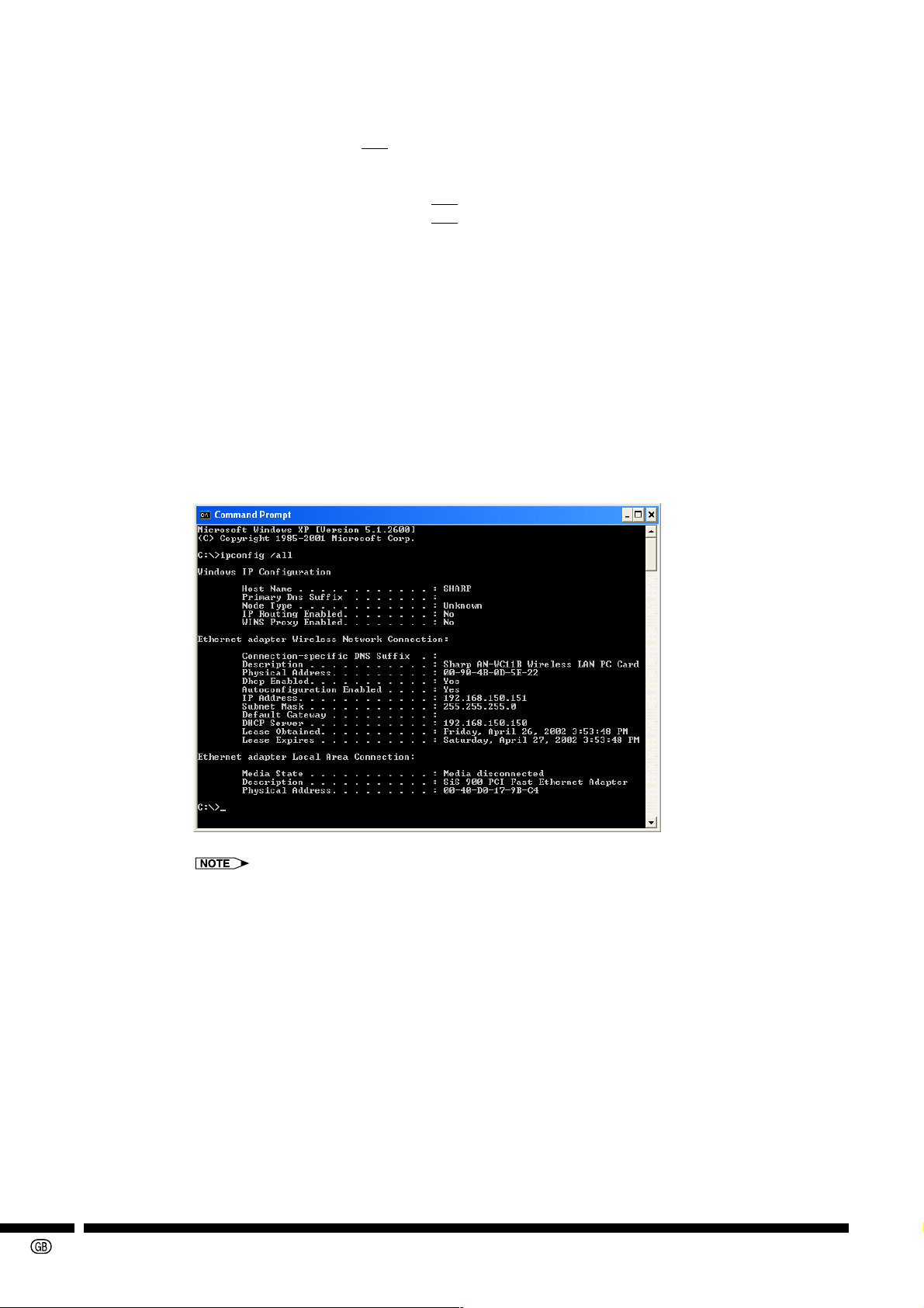
• Check the set values when automatically receiving an IP address from the DHCP server.
1
Open Command Prompt (MS-DOS Prompt).
Windows 98/98SE: Start →Programs →MS-DOS Prompt
Windows Me: Start → Programs → Accessories → MS-DOS Prompt
Windows 2000: Start → Programs → Accessories → Command Prompt
Windows XP: Start → All Programs → Accessories → Command Prompt
2
After the Command Prompt window has opened, enter the “ipconfig/all” command.
C:\> ipconfig /all [ENTER]
-30
“ipconfig” example
C:\> ipconfig /? Displays how to use ipconfig.exe.
C:\> ipconfig Displays the set IP address.
C:\> ipconfig /all Displays all information related to the set TCP/IP.
• If the value of the received IP address is 169.254.XXX.XXX
The reception of the IP address from the DHCP server has failed.
When the DHCP server function fails to receive an address, the address 169.254.XXX.XXX is
automatically allocated.
(The XXX.XXX part of the IP address is randomly selected.)
1 The projector (on the DHCP server) is not active before Windows restarts.
2 Check that the Wireless LAN settings and the driver are properly set.
3 Check that the projector’s DHCP server function is properly set.
If the above is in order, restart the computer.

• Using the “PING” command, you can check if the “TCP/IP” is operating correctly. You can also
check if the IP address is set.
1
Open Command Prompt (MS-DOS Prompt).
Windows 98/98SE: Start → Programs → MS-DOS Prompt
Windows Me: Start → Programs → Accessories → MS-DOS Prompt
Windows 2000: Start → Programs → Accessories → Command Prompt
Windows XP: Start → All Programs → Accessories → Command Prompt
2
After the Command Prompt window has opened, enter the “PING” command.
Example: C:\> ping
XXX.XXX.XXX.XXX
3
The following will be displayed if a successful connection is made.
The screen image may appear slightly different depending on the operating system.
Example: When the Host IP Address 192.168.150.150
XXX.XXX.XXX.XXX
is the Host IP Address.
4
If a connection cannot be made, “Request timed out” is displayed.
Recheck the wireless LAN settings and the network settings.
If all else fails, consult your Network Administrator.
5
To return to the Windows desktop, type “exit”, and then press the “Enter” key.
-31

12. Glossary
Access point
Device used for relaying transmissions when using the “Access Point”.
Can be used for relaying transmissions between wireless LAN devices and wired LAN devices as
well as relaying transmissions between wireless LAN devices.
AdHoc (Peer-to-Peer) mode
A type of wireless transmission.
Mode used for exchanging data between devices that have wireless LAN PC cards installed,
without going via an access point.
Channel
Wireless LAN devices that comply with IEEE802.11b transmit using a specified wireless channel
from wireless channels 1 to 14. (This device has 11 channels (1 to 11) that can be used. The
channels that can be used vary with the country or region.)
It may be possible to use the same channel on a different network, however, the transmission
speed may be reduced.
It is recommended to use a different channel.
DHCP (Dynamic Host Configuration Protocol)
When building a TCP/IP network, it is necessary to assign IP addresses to devices on the network.
This protocol assigns IP address automatically.
DHCP client function
This function allows for automatically receiving IP addresses from DHCP servers connected to the
same network.
This function is found in most computers. If the computer is connected to the DHCP server on the
network, it is also possible to automatically get an IP address for the computer.
DHCP server
This server allows automatically assigning IP addresses, subnet masks, and gateway addresses to
devices connected on the network. By using this function, a computer connected to the DHCP
server via a wireless connection can also automatically receive an IP address.
Gateway
Device which relays transmissions between different networks.
IEEE802.11b
One of the international standards for wireless LANs. Allows for wireless transmissions using a
wireless frequency of 2.4GHz and a maximum speed of 11Mbps.
Infrastructure (Access Point) mode
A type of wireless transmission.
Mode used for exchanging data between devices connected to wired LANs and devices connected
to wireless LANs.
IP Address
When configuring a network using TCP/IP protocol, every device must have a number assigned to
it. This number is called an IP address.
An IP address is necessary to avoid duplicates or overlapping on the network.
-32
LAN (Local Area Network)
A network built in a comparatively narrow area.

MAC Address (Media Access Control Address)
A fixed number assigned to individual network devices.
It is assigned by the manufacturer at the time of shipping and does not overlap with other devices.
Subnet Mask
A parameter used on a TCP/IP network, that is used when an IP address is separated into network
address and host address.
SS ID (Service Set Identification)
An ID (extension) for grouping multiple wireless LAN devices. An SS ID equal to other devices
must be set to communicate with them.
A maximum of 32 single-byte alphanumeric characters can be used.
Letters are categorized as capital and lower case.
TCP/IP (Transmission Control Protocol/Internet Protocol)
Standard protocol for using the Internet or LANs.
WEP (Wired Equivalent Privacy)
A method of encrypting data when sending over wireless transmissions.
A shared key of 64 bits or 128 bits can be used.
-33

13. Wireless LAN PC Card Specifications
Product Name 11 Mbps Wireless LAN PC Card
Model Number AN-WC11B (RUNTKA025WJZZ)
Host Interface PCMCIA TYPE II
Dimensions 2 1⁄8" × 4 1⁄2" × 1⁄4" (54 (W) × 115 (D) × 6 (H) mm)
Weight 0.09lbs (40 g)
Frequency Band 2.4000 – 2.4835 GHz
(Central frequency)
Number of Channel 1~11 (Channels that can be used vary depending on the country.)
Operating Voltage 3.3 V ± 5% or 5 V ± 5%
Current Consumption Typ. 240 mA, Max. 300 mA
Spreading DS-SS (Direct Sequence Spread Spectrum)
Data rate 11 Mbps, 5.5 Mbps, 2 Mbps, 1 Mbps (Auto-Switch)
Transmit Power 10 dBm (Normal Temp Range) 13 dBm (Max.)
Modulation 11 Mbps, 5.5 Mbps: CCK
2 Mbps: DQPSK
1 Mbps: DBPSK
Security WEP (64 bit/128 bit) (not compatible with the projector)
Standards IEEE802.11b
Media Access Protocol CSMA/CA with ACK
Environmental Conditions Temperature Range 32 to 131°F (0 to 55°C) (Operating)
Humidity Max. 95% Non-condensing
Operating Range Open Space: 197' to 394' (60 to 120 m); Indoor: 98' to 196' (30 to 60 m)
The transmission distance varies with the transmission speed and the
surrounding environment.
Supported OS Microsoft Windows 98, 98SE, Me, 2000 Professional, XP Home Edition,
XP Professional Edition. (Japanese and English versions)
-34

14. Index
802.11 AdHoc (“Peer-to-Peer”) mode ..............................................................................................23
About ................................................................................................................................................27
Access point ................................................................................................................................19,23
AdHoc (“Peer-to-Peer”) channel ......................................................................................................24
Channel .......................................................................................................................................17,21
Configuration ....................................................................................................................................22
Default gateway................................................................................................................................18
DHCP ...............................................................................................................................................29
Disable Radio ...................................................................................................................................21
Enable Radio ....................................................................................................................................21
Encryption.........................................................................................................................................25
Encryption key ..................................................................................................................................25
Infrastructure (“Access Point”) mode ...............................................................................................23
Install ..................................................................................................................................................9
IP address ........................................................................................................................................18
LINK indicator .....................................................................................................................................6
Link Quality .......................................................................................................................................21
MAC address ....................................................................................................................................21
PCMCIA connector.............................................................................................................................6
Profile ...............................................................................................................................................22
Rescan .............................................................................................................................................21
Signal strength .................................................................................................................................21
SS ID ................................................................................................................................................23
State .................................................................................................................................................21
Subnet mask..................................................................................................................................... 18
Throughput .......................................................................................................................................21
Transmission mode ..........................................................................................................................23
Transmission Status .........................................................................................................................21
Transmit Rate ..............................................................................................................................21,24
Uninstall ............................................................................................................................................16
WEP .................................................................................................................................................25
Wireless LAN ....................................................................................................................................21
-35

For SHARP Assistance
If you encounter any problems during setup or operation of the Wireless LAN PC Card, first refer to
the “11. Troubleshooting” section on page 28. If this operation manual does not answer your
question, please contact the SHARP Service departments listed below.
U.S.A. Sharp Electronics Corporation
1-888-GO-SHARP (1-888-467-4277)
lcdsupport@sharpsec.com
http://www.sharplcd.com
Canada Sharp Electronics of Canada Ltd.
(905) 568-7140
http://www.sharp.ca
Mexico Sharp Electronics Corporation Mexico
Branch
(525) 716-9000
http://www.sharp.com.mx
Latin America Sharp Electronics Corp. Latin American
Group
(305) 264-2277
www.servicio@sharpsec.com
http://www.siempresharp.com
Germany Sharp Electronics (Europe) GMBH
01805-234675
http://www.sharp.de
U.K. Sharp Electronics (U.K.) Ltd.
0161-205-2333
custinfo@sharp-uk.co.uk
http://www.sharp.co.uk
Italy Sharp Electronics (Italy) S.P.A.
(39) 02-89595-1
http://www.sharp.it
France Sharp Electronics France
01 49 90 35 40
hotlineced@sef.sharp-eu.com
http://www.sharp.fr
Spain Sharp Electronica Espana, S.A.
93 5819700
sharplcd@sees.sharp-eu.com
http://www.sharp.es
Switzerland Sharp Electronics (Schweiz) AG
0041 1 846 63 11
cattaneo@sez.sharp-eu.com
http://www.sharp.ch
Austria Sharp Electronics Austria (Ges.m.b.H.)
0043 1 727 19 123
pogats@sea.sharp-eu.com
http://www.sharp.at
Australia Sharp Corporation of Australia Pty. Ltd.
1300-135-022
http://www.sharp.net.au
New Zealand Sharp Corporation of New Zealand
(09) 634-2059, (09) 636-6972
http://www.sharpnz.co.nz
Singapore Sharp-Roxy Sales (S) Pte. Ltd.
65-226-6556
ckng@srs.global.sharp.co.jp
http://www.sharp.com.sg
Hong Kong Sharp-Roxy (HK) Ltd.
(852) 2410-2623
dcmktg@srh.global.sharp.co.jp
http://www.sharp.com.hk
Malaysia Sharp-Roxy Sales & Service Co.
(60) 3-5125678
U.A.E. Sharp Middle East Fze
971-4-81-5311
helpdesk@smef.global.sharp.co.jp
Thailand Sharp Thebnakorn Co. Ltd.
02-236-0170
svc@stcl.global.sharp.co.jp
http://www.sharp-th.com
Korea Sharp Electronics Incorporated of Korea
(82) 2-3660-2002
webmaster@sharp-korea.co.kr
http://www.sharp-korea.co.kr
India Sharp Business Systems (India) Limited
(91) 11- 6431313
service@sharp-oa.com
Sweden Sharp Electronics (Nordic) AB
(46) 8 6343600
vision.support@sen.sharp-eu.com
http://www.sharp.se
-36
 Loading...