

Page 1
1
AH-S22DP2
AH-S25DP2
AH-S32DP2
S3313AHS32DP2
SPLIT TYPE
ROOM AIR CONDITIONERS
In the interests of user-safety (Required by safety regulations in some
countries) the set should be restored to its original condition and only parts
identical to those specified should be used.
SERVICE MANUAL
Page
SPECIFICATIONS ............................................................................................................................................. 2
EXTERNAL DIMENSIONS ................................................................................................................................. 3
WIRING DIAGRAMS ......................................................................................................................................... 4
ELECTRICAL PARTS ......................................................................................................................................... 6
BLOCK DIAGRAM ..............................................................................................................................................7
MICROCOMPUTER CONTROL SYSTEM ......................................................................................................... 9
FUNCTIONS .................................................................................................................................................... 15
FUNCTION AND OPERATION OF PROTECTIVE PROCEDURES ............................................................... 22
BREAKDOWN DIAGNOSIS PROCEDURE .................................................................................................... 24
REFRIGERATION CYCLE .............................................................................................................................. 27
PERFORMANCE CURVES ............................................................................................................................. 28
DISASSEMBLING PROCEDURE .................................................................................................................... 29
OPTION ........................................................................................................................................................... 36
REPLACEMENT PARTS LIST ........................................................................................................................ 38
TABLE OF CONTENTS
MODELS
SHARP CORPORATION
AH-S22DP2
AH-S25DP2
AH-S32DP2
OUTDOOR UNIT
INDOOR UNIT
AU-S22DP2
AU-S25DP2
AU-S32DP2
Page 2
2
AH-S22DP2
AH-S25DP2
AH-S32DP2
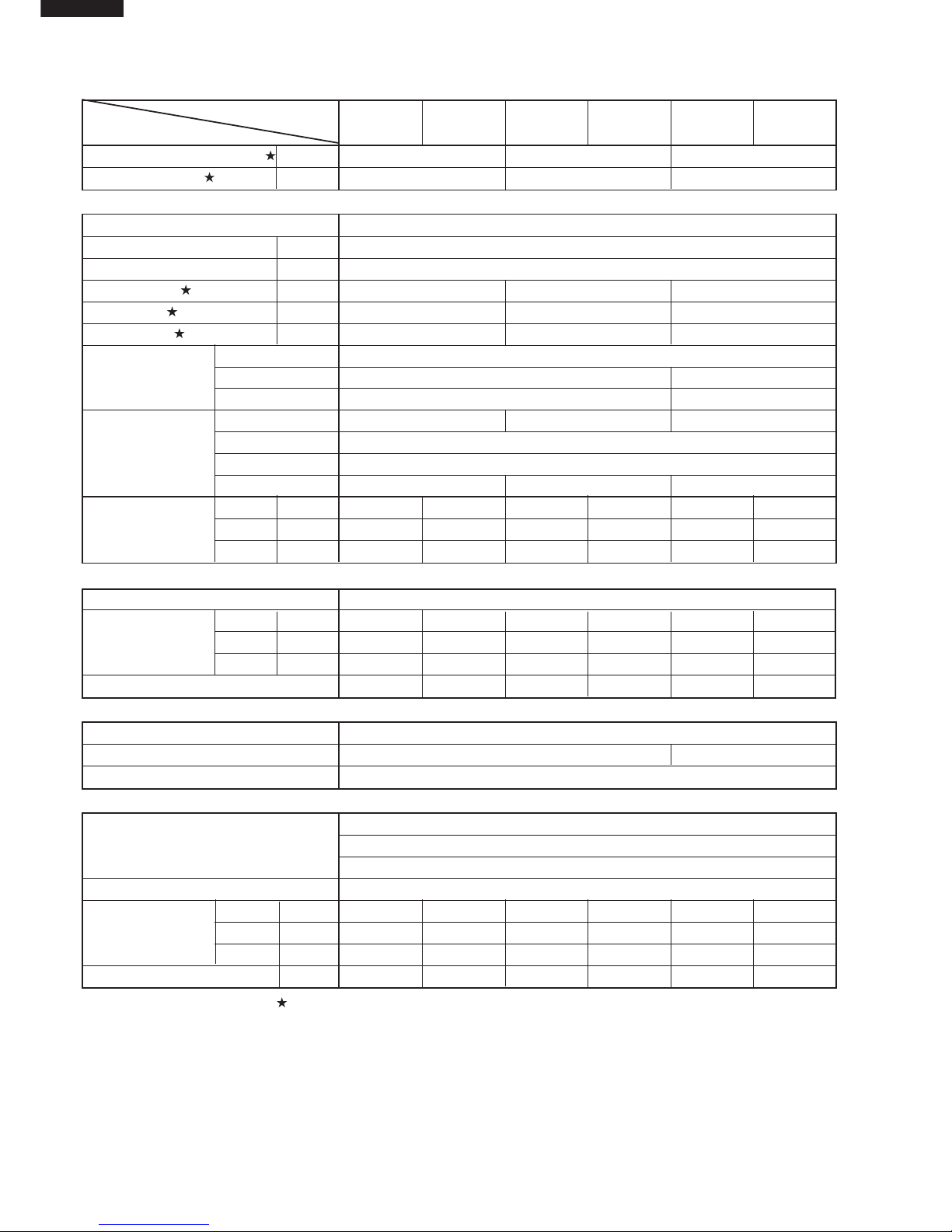
SPECIFICATIONS
MODEL
I
NDOOR UNIT
OUTDOOR UNIT
INDOOR UNIT
OUTDOOR UNIT
INDOOR UNIT
OUTDOOR UNIT
ITEMS AH-S22DP2 AU-S22DP2 AH-S25DP2 AU-S25DP2 AH-S32DP2 AU-S32DP2
Cooling capacity(Min. ~ Max.)
k/W 2.0 (1.0 - 2.6) 2.1 (1.0 - 2.9) 2.7 (0.9 - 3.7)
Moisture removal
Liters/h 0.7 0.8 0.9
Electrical data
Phase Single
Rated frequency Hz 60
Rated voltage V 220
Rated current A3.6 3.74.5
Rated input (Min. - Max.) W 720(400 - 1050) 730(400 - 1200) 900(330 - 1500)
Power factor %91 9091
Type Hermetically sealed rotary type
Compressor Model 2RV110N5EA04 HV237A1-S15DK
Oil charge ATMOS M60 or SUNISO 4GDID 260 cm
3
SUNISO 4GSD 455 cc
Evaporator Bare tube type Grooved tube type Grooved tube type
Refrigerant system Condenser Louver Fin and Grooved tube type
Control Capillary tube
Refrigerant volume
510g 530g 750g
Noise level
High dB(A) 35 43 36 43 38 48
(at cooling)
Med. dB(A) 31 – 32 – 33 Low dB(A) 26 – 27 – 29 -
Fan system
Drive Direct drive
Air flow quantity High m3/min. 7.5 29 8.0 29 9.4 32
(at cooling) Med. m3/min. 6.5 – 7.0 – 8.0 –
Low m3/min. 5.1 – 5.2 – 6.5 –
Fan
Cross flow fan Propeller fan Cross flow fan Propeller fan Cross flow fan Propeller fan
Connections
Refrigerant coupling Flare type
Refrigerant tube size Gas, Liquid 3/8", 1/4" 1/2", 1/4"
Drain piping mm O.D ø 18
Others
Compressor: Thermal protector
Safety device Fan motors: Thermal fuse
Fuse, Micro computer control
Air filters Polypropylene net (Washable)
Width mm 815 780 815 780 815 780
Net dimensions Height mm 278 540 278 540 278 540
Depth mm 198 269 198 269 198 269
Net weight kg 9 31 9 33 10 38
Note: The condition of star " " marked item are 'CNS14464 B 7291 : T1'.
Page 3
3
AH-S22DP2
AH-S25DP2
AH-S32DP2
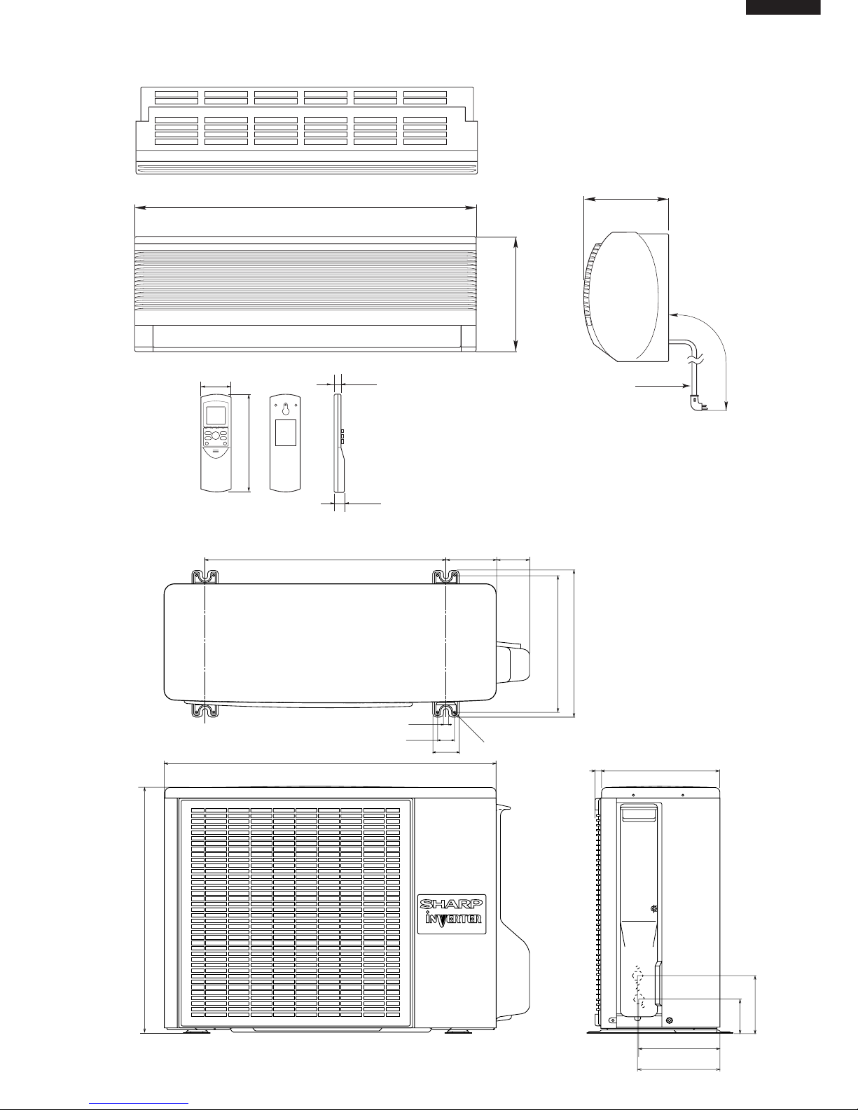
EXTERNAL DIMENSIONS
Figure E-1. INDOOR UNIT
Figure E-2. OUTDOOR UNIT
269
179.5
182.5
136
81
780
70
540
310
335
540
12
37.5
4.5
58
158
16
815
278
198
Length unit (mm)
22.0
58
CRMC-A442JBE0
R03(AAA) 2PCS.
SHARP CORPORATION
INVERTER AIR CONDITIONER
18.5
175
1700
Power supply cord
Page 4
4
AH-S22DP2
AH-S25DP2
AH-S32DP2
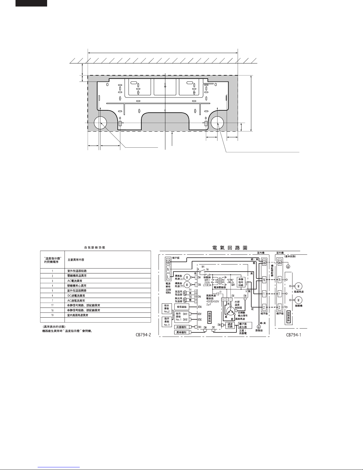
WIRING DIAGRAMS
Figure E-3. INSTALLATION DIMENSIONS
815 (unit size)
More than 50mm
E
Center of wall hole:
Leftward piping
Center of wall hole: Backward piping
Outline of indoor unit
55 95
80 55
AJ
IF
E
D
D
FA
C
J
H
I
GB
21
278 (unit size)
38
Ceiling
E
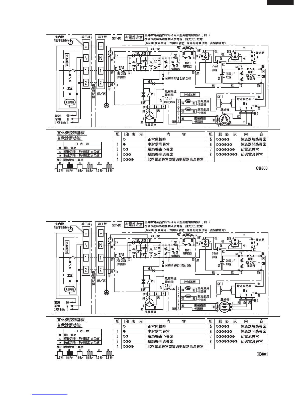
Figure W-1. Wiring Diagram for AH-S22DP2/S25DP2/S32DP2
Page 5
5
AH-S22DP2
AH-S25DP2
AH-S32DP2
Figure W-2. Wiring Diagram for AU-S22DP2/S25DP2
Figure W-3. Wiring Diagram for AU-S32DP2
Page 6
6
AH-S22DP2
AH-S25DP2
AH-S32DP2
For Model AH-S22DP2/S25DP2/S32DP2
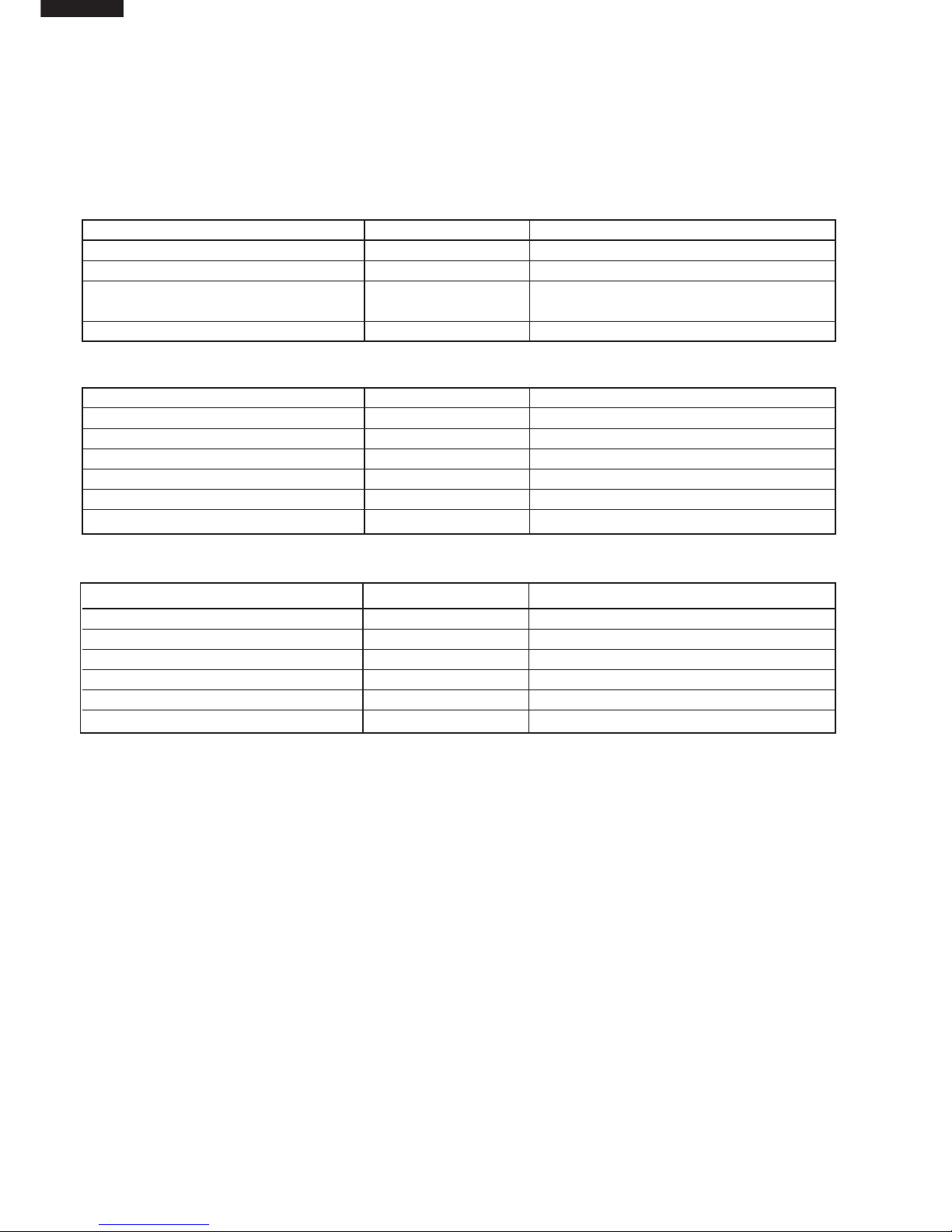
DESCRIPTION MODEL REMARKS
Indoor fan motor ML-A901 220 - 240V, 50Hz 220 - 230V, 60Hz
Indoor fan motor capacitor – 430V or 450V, 2µF
Transformer – Primary; AC 220 - 240V, 50/60Hz
Secondary; AC19V
WPE1 – QFS-GA053JBZZ (2.5A, 250V)
For Model AU-S22DP2/S25DP2
DESCRIPTION MODEL REMARKS
Compressor 2RV110N5EA04 3-PHASE Induction motor
Outdoor fan motor ML-A902 220 - 240V, 50Hz 220 - 230V, 60Hz
Outdoor fan motor capacitor – 430V or 450V, 1.5µF
WPE1 – QFS-GA033JBZZ(15A, 250V)
WPE2 – QFS-GA015JBE0(10A, 250V)
WPE3 – QFS-GA054JBZZ (3.15A, 250V)
For Model AU-S32DP2
DESCRIPTION MODEL REMARKS
Compressor HV237A1-S15DK 3-PHASE Induction motor
Outdoor fan motor ML-A903 220 - 240V, 50Hz 220V, 60Hz
Outdoor fan motor capacitor – 430V or 450V, 2µF
WPE1 – QFS-GA014JBE0(20A, 250V)
WPE2 – QFS-GA019JBE0(20A, 250V)
WPE3 – QFS-GA054JBZZ (3.15A, 250V)
ELECTRICAL PARTS
Page 7
7
AH-S22DP2
AH-S25DP2
AH-S32DP2
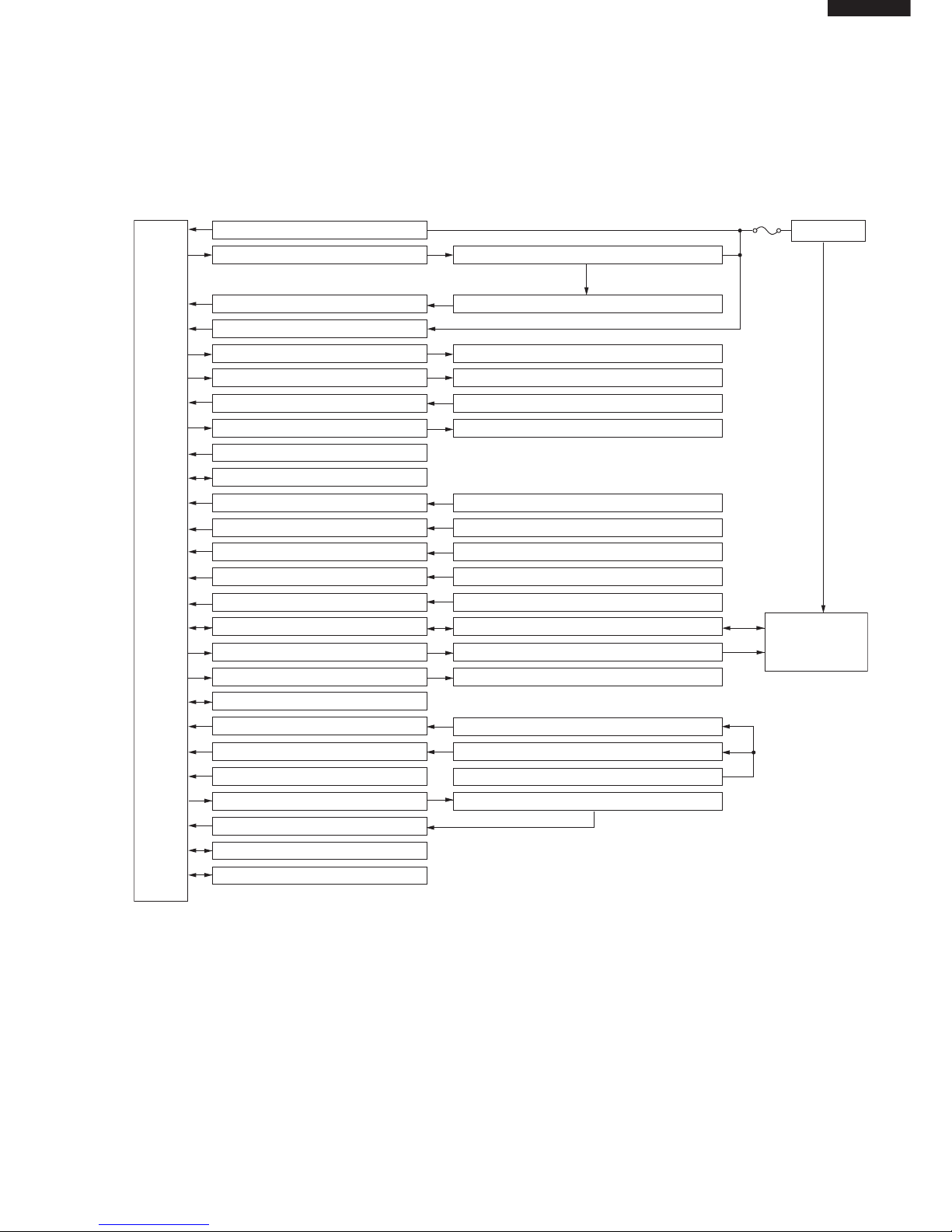
BLOCK DIAGRAMS
INDOOR UNIT
AC power
CPU
2.5A
protection
DC power supply circuit
Fan motor phase control circuit
Rotation pulse input circuit
AC clock circuit
Louvre motor drive circuit(upper)
Louvre motor drive circuit(lower)
Remote controller signal reception circuit
Buzzer drive circuit
CPU reset circuit
CPU oscillator circuit
Room temp. detect circuit
Heat exchanger pipe thermo circuit
Compensation circuit/ select circuit
Compensation circuit
Switchover circuit
Serial I/O circuit
Compressor relay drive circuit
LED drive circuit
Auto restart circuit
Test run circuit
Auxiliary mode
Power on circuit
Cluster generator drive circuit
Cluster generator sensor circuit
Gas sensor circuit
Dust sensor circuit
Indoor fan motor
Fan motor pulse detect
Flow direction control (louver motor upper)
Flow direction control (louver motor lower)
Wireless remote control operation
Audible operation confirmation
Room temp. thermistor
Heat exchanger pipe thermistor
Blower temperature, fan speed, model select
Outdoor ratings
Wireless, preheat
Indoor/outdoor control signal I/O
Outdoor unit power supply on/off control
LED display
Test run (forced operation)
Auxiliary mode button ON/OFF
Self diagnostics, fault diagnosis
Cluster generator
Unit-unit wiring
(AC power and
serial signals)
Page 8
8
AH-S22DP2
AH-S25DP2
AH-S32DP2
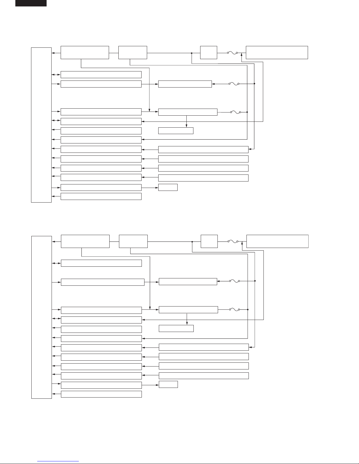
CPU
15 A
protection
Outdoor fan motor
4-way valve(except for
the AU-X08BE/X10BE)
Power transistor module
Compressor
Current transformer
Compressor thermistor
Heat exchanger pipe thermistor
Outdoor temperature thermistor
LED
3.15 A
protection
10 A
protection
Power supply circuit
(built into IPM)
CPU oscillator circuit
Outdoor fan motor relay drive circuit
4-way valve relay drive circuit
(except for the AU-X08BE/X10BE)
Power transistor module drive circuit
Serial I/O circuit
CPU reset circuit
DC overcurrent detection circuit
AC overcurrent detection circuit
Compressor thermo circuit
Heat exchanger pipe thermo circuit
Outdoor temp. thermo. circuit
LED drive circuit
Test mode circuit
Filter
circuit
Smoothing
circuit
Unit-unit wiring (AC power
and serial signals)
CPU
20 A
protection
Outdoor fan motor
4-way valve(except for
the AU-X13BE)
Power transistor module
Compressor
Current transformer
Compressor thermistor
Heat exchanger pipe thermistor
Outdoor temperature thermistor
LED
3.15 A
protection
20 A
protection
Power supply circuit
(built into IPM)
CPU oscillator circuit
DC overvoltage detection circuit
Outdoor fan motor relay drive circuit
4-way valve relay drive circuit
(except fot the AU-X13BE)
Power transistor module drive circuit
Serial I/O circuit
CPU reset circuit
DC overcurrent detection circuit
AC overcurrent detection circuit
Compressor thermo circuit
Heat exchanger pipe thermo circuit
Outdoor temp. thermo. circuit
LED drive circuit
Test mode circuit
Filter
circuit
Smoothing
circuit
Unit-unit wiring (AC power
and serial signals)
OUTDOOR UNIT for AU-S22DP2/S25DP2
OUTDOOR UNIT for AU-S32DP2
Page 9
9
AH-S22DP2
AH-S25DP2
AH-S32DP2
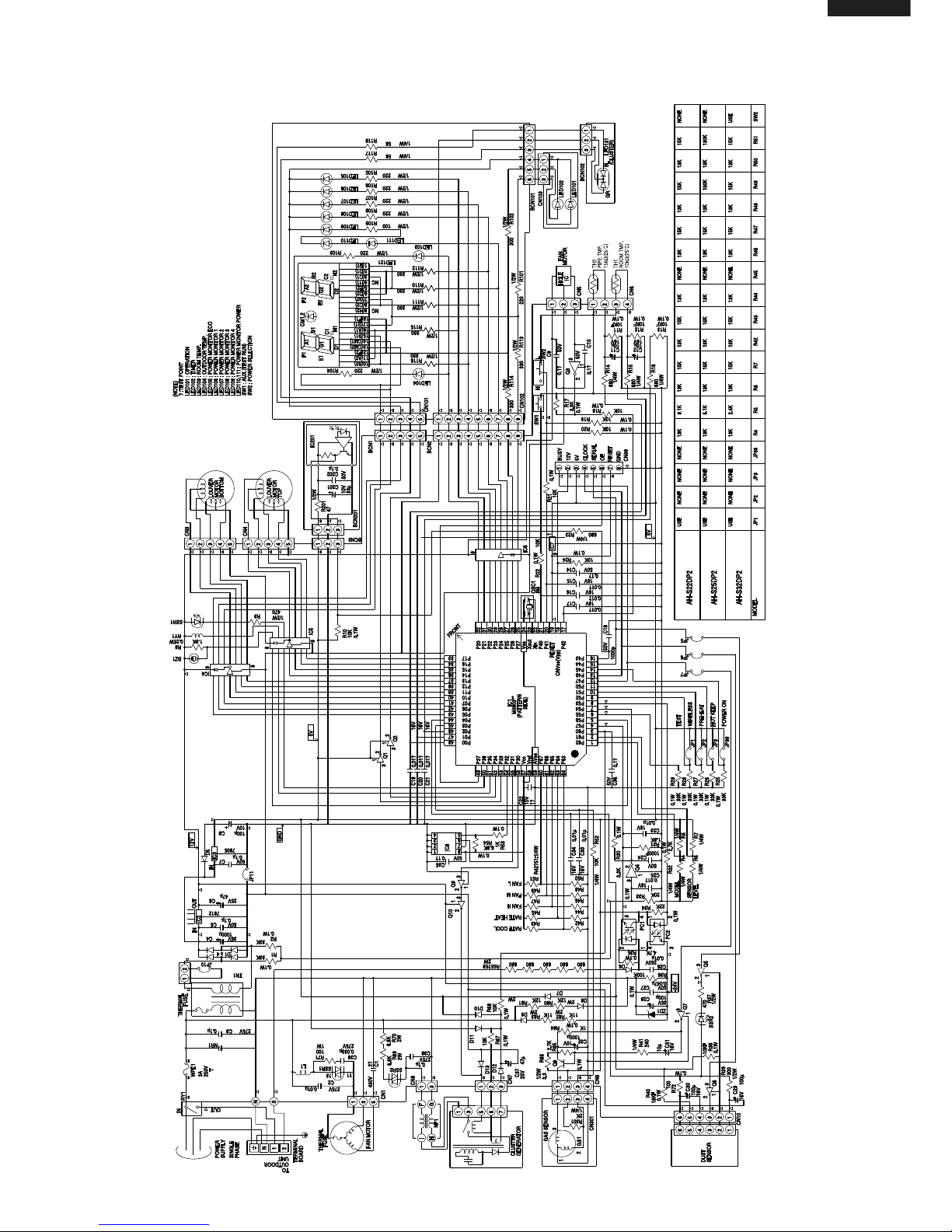
MICROCOMPUTER CONTROL SYSTEM
Figure L-1. Electronic Control Circuit Diagram for AH-S22DP2/S25DP2/S32DP2
Page 10
10
AH-S22DP2
AH-S25DP2
AH-S32DP2
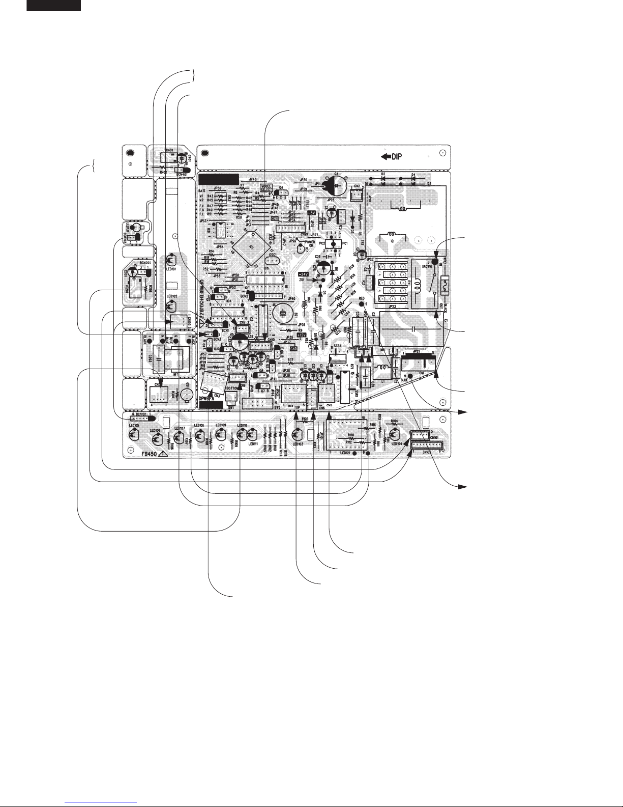
Figure L-2 Printed Wiring Board for AH-S22DP2/S25DP2/S32DP2
TOCLUSTERGENERATOR
FROMCLUSTERGENERATOR
FROMDUSTSENSOR
BCN201
or
BCN401
FROM
TERMINALLOF
TERMINALBOARD3
P
(BROWN)
FROM
TERMINAL1OF
TERMINALBOARD4
P
(BLACK)
TO
TERMINALNOF
TERMINALBOARD4
P
(BLUE)
TO
TERMINAL2OF
TERMINALBOARD4
P
(RED)
FROM
FANMOTOR
FROMFANMOTOR
FROMLOUVREMOTOR(TOP)
FROMLOUVREMOTOR(BOTTOM)
FROMTHERMISTOR
Page 11
11
AH-S22DP2
AH-S25DP2
AH-S32DP2
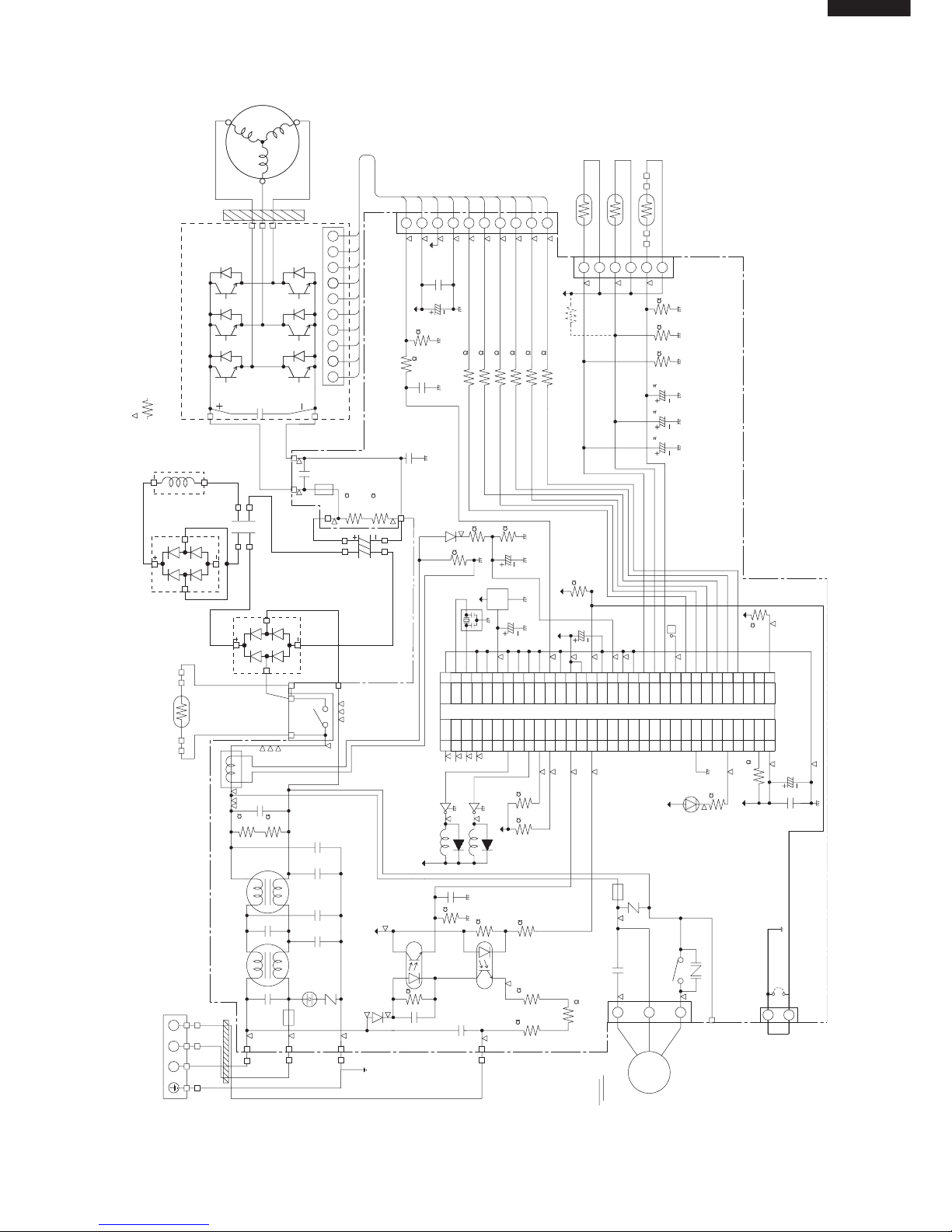
Figure L-3. Electronic Control Circuit Diagram for AU-S22DP2/S25DP2
DB1
DB2
WHITE
DB~
DB~
DB~ DB~
BLUE
BLUE
ORANGE
ORANGE
ORANGE
L1
ORANGE
C6
RED
200V 75∝F
420V 1500∝F
C8
TB (TERMINAL BOAOD)
1
N
2
1
2
3
4
BROWN
BLUE
GREEN / YELLOW
RED
FC1
T2
T1
T4
T3
L3 L4
C31
275V 1∝F
C4
250V 2200pF
1
2
3
4
C2
275V 1∝F
C3
250V 2200pF
C34
250V 2200pF
WPE1
250V
15A
C1
275V 1∝F
C33
250V 2200pF
R2 R1
1/4W
510K
1/4W
510K
CT1
T5
T6
MRY1
PTC
BLUE
GRAY
GRAY
BLACK
RED
C30
25V 100∝F
C11
25V 0.1∝F
C18
50V 0.1∝F
R35
510
R36
510
BLUE
NOTE
1. MARK IS TEST POINT.
2. IF NOT SPECIFIED 1/4W (RESISTOR)
YELLOW
T9
T10
T7
C10
630V 0.33∝F
R39
1/2W
270K
250V
10A
WPE2
13V
5V
R40
1/2W
270K
T8
C32
250V 2200pF
1 : Red 2-10 : White
10
987654321
10
987654321
CN11 (CONTROL PWB)
U
V
W
QM1 (IPM)
TM-31T
FC2
RED
WHITE
BLACK
U
V
W
R33
R32
R31
R30
R29
R28
390 U
390 X
390 V
390 Y
390 W
390 Z
65432
1
BCN11
CN8
TH3
(THERMISTOR for OUTDOOR TEMP.)
TH2
(THERMISTOR for HEAT-EXCHANGER)
TH1
(THERMISTOR for COMPRESSOR)
R38
6.8K F
C26
16V 10 F
5V
C22
16V 10 F
C21
16V 10 F
R21
6.8K F
R20
6.8K F
C15
10V 220∝F
R10
6.8K F
R8
2.7K F
R9
1.00K F
D2
1
2
3
1
2
3
5V
C23
50V 1∝F
PST
993D
IC3
OSC1
10MHz
5V
5V
C17
10V 100∝F
F
R46
10K
R34
10K
NC
NC
5V
33343536373839404142434445464748495051525354555657585960616263
64
32313029282726252423222120191817161514131211100908070605040302
01
P27
P26
P25
P24
P23
P22
P21
P20
P17
P16
P15
P14
P13
P12
P11
P10
P07
P06
P05
P04
P03
P02
P01
P00
V
SS
P37
P36
P35
P34
P33
P32
V
CC
VSSXIX0MOD1
MOD2
RST
P60
P61
P62
P63
P64
AVSSAVR
AVCCAN7
AN6
AN5
AN4
AN3
AN2
AN1
AN0
P40
P41
P42
P43
P44
P45
P46
P47
P30
P31
NCNCNC
NC
NCNCNCNCNCNCNCNCNCNCNCNCNC
IC1 MB89855
C16
25V 0.1∝F
C20
10V 100∝F
5V
R41 10K
R3
2.2K
5V
LED1
C5
430V or 450V
1.5
µF
WPE3
250V
3.15A
NR2
Fan
Motor
5
3
1
CN3
T11
RY1
CNR1
(WINTER KIT)
C12
250V 4700pF
C14
50V 1000pF
C13
25V 0.01∝F
R4
D1
3.3K
R6
2.7K
R5
5.6K
R7
4.7K
PC817X7
PC1
PC2
PC853H
1
23
4
1
23
4
5V
R11
2W 1.0K
R12
2W 1.0K
R13
2W 1.0K
R17
10K
R16
10K
13V
RY1
D6
Q1
MRY1
D8
Q3
5V
NR1
SA1
TEMPERATURE
FUSE 103˚C
CN9
JP1
2
1
Page 12

12
AH-S22DP2
AH-S25DP2
AH-S32DP2
Figure L-4. Electronic Control Circuit Diagram for AU-S32DP2
DB1
DB2
WHITE
DB~
DB~
DB~ DB~
BLUE
BLUE
ORANGE
ORANGE
ORANGE
L1
ORANGE
C6
RED
200V 90µF
400V 2000µF
C8
TB (TERMINAL BOARD)
TEMPERATURE
FUSE 103˚C
21
N
1
2
3
4
BLUE
OWN
RED
FC1
T2
T1
T4
T3
L3 L4
C31
275V 1∝F
C4
250V 2200pF
1
2
3
4
C2
275V 1∝F
C3
250V 2200pF
C34
250V 2200pF
WPE1
250V
20A
C1
275V 1∝F
C33
250V 2200pF
R2 R1
1/4W
510K
1/4W
510K
CT1
T5
T6
MRY1
PTC
BLUE
GRAY
GRAY
BLACK
RED
C30
25V 100∝F
C11
25V 0.1∝F
C18
50V 0.1∝F
R35
510
R36
510
BLUE
NOTE
1. MARK IS TEST POINT.
2. IF NOT SPECIFIED 1/4W (RESISTOR)
YELLOW
T9
T10
T7
C10
630V 0.33∝F
R39
1/2W
270K
250V
20A
WPE2
13V
5V
R40
1/2W
270K
T8
C32
250V 2200pF
1 : Red 2-10 : White
10
987654321
10
987654321
CN11 (CONTROL PWB)
U
V
W
QM1 (IPM)
TM-35
FC2
RED
WHITE
BLACK
U
V
W
R33
R32
R31
R30
R29
R28
430 U
430 X
430 V
430 Y
430 W
430 Z
65432
1
BCN11
CN8
TH3
(THERMISTOR for OUTDOOR TEMP.)
TH2
(THERMISTOR for HEAT-EXCHANGER)
TH1
(THERMISTOR for COMPRESSOR)
R38
6.8K F
C26
16V 10 F
5V
C22
16V 10 F
C21
16V 10 F
R21
6.8K F
R20
6.8K F
C15
10V 220∝F
R10
6.8K F
R8
2.7K F
R9
1.00K F
D2
1
2
3
1
2
3
5V
C23
50V 1∝F
PST
993D
IC3
OSC1
10MHz
5V
5V
C17
10V 100∝F
F
R46
10K
R34
10K
NC
NC
5V
33343536373839404142434445464748495051525354555657585960616263
64
32313029282726252423222120191817161514131211100908070605040302
01
P27
P26
P25
P24
P23
P22
P21
P20
P17
P16
P15
P14
P13
P12
P11
P10
P07
P06
P05
P04
P03
P02
P01
P00
V
SS
P37
P36
P35
P34
P33
P32
V
CC
VSSXIX0MOD1
MOD2
RST
P60
P61
P62
P63
P64
AVSSAVR
AVCCAN7
AN6
AN5
AN4
AN3
AN2
AN1
AN0
P40
P41
P42
P43
P44
P45
P46
P47
P30
P31
NCNCNC
NC
NCNCNCNCNCNCNCNCNCNCNCNCNC
IC1 MB89855
C16
25V 0.1∝F
C20
10V 100∝F
5V
R41 10K
R3
2.2K
5V
LED1
C5
430V or 450V
2.0
µF
WPE3
250V
3.15A
NR2
Fan
Motor
5
3
1
CN3
T11
RY1
CNR1
(WINTER KIT)
C12
250V 4700pF
C14
50V 1000pF
C13
25V 0.01∝F
R4
D1
3.3K
R6
2.7K
R5
5.6K
R7
4.7K
PC817X7
PC1
PC2
PC853H
1
23
4
1
23
4
5V
R11
2W 1.0K
R12
2W 1.0K
R13
2W 1.0K
R17
10K
R16
10K
13V
RY1
D6
Q1
MRY1
D8
Q3
5V
NR1
SA1
CN9
JP1
2
1
Page 13
13
AH-S22DP2
AH-S25DP2
AH-S32DP2
T5(DB1~)
(BLACK)
C5
NR2
WPE3
R2
R1
C
T
1
3A 250V
RY1
CNR1
T11
(GRAY)
T10
T9
WPE2
20A
250V
(BLUE)
(YELLOW)
IPM
R33
R32
R31
R30
R29
R28
C10
R40
R39
JP1
R46
C33
Q2
C1
SA1
D7
JP2
JP17
JP19
JP18
(FAN MOTOR)
CN3
1
5
IPM
(RED)
(BLUE)
T7
CB
T8
CB
JP16
JP20
C17
R35
R36
JP25
C18
C23
R20
C21
R13
R12
R11
C22
C26
R21
R38
F
JP21
R10
JP22
IC3
C15
OSC1
R4
C12
C31
D1
R16
C13
R17
JP12
R7
C14
JP13
R6
R5
R5
PC2
PC1
C3
3
4
1
2
2
1
4
3
L3
C4
L4
C34
C2
NR1
WPE1
25A 250V
OUT
32
33
32
IC1
1
CN8
(THERMISTOR)
16
64
C20
LED1
R59
D8
C30
E
C
B
B
C
E
B
C
E
Q4
R3
R41
C12
JP7
JP6
R9
D2
R8
JP3
JP5
JP4
R60
121
BCN11 (IPM)
JP8
JP9
JP10
JP11
C16
Q3
Cool/40Hz
QPWBFB399JBZZ
DPWBFA
JBKZ
0
MRY1
PTC
(BLUE)
IN
(GRAY)
(DB1~)
(RED)
(BLUE)
(BROWN)
(GREEN/
YELLOW)
T3
T2
2
N
1
T1
T4
DIP
T6(GRAY)
PTC
R34
C32
JP14
JP15
GND
13V
5V
TERMINAL
FUSE
FROM
FAN MOTOR
FROM
POWER TRANSISTOR
MODULE QM1 " "
FROM
POWER TRANSISTOR
MODULE QM1 " "
FROM
ELECTLYTIC
CAPACITOR
C8 " "
FROM
ELECTLYTIC
CAPACITOR
C8 " "
FROM
THERMISTOR
FROM
TERMINAL
BOARD " N "
FROM
TERMINAL
BOARD " 2 "
FROM
TERMINAL
BOARD " 1 "
FROM
CONTROL BOX
FROM
DIODE BRIDGE
DB1 " ~ "
FROM
DIODE BRIDGE
DB1 " ~ "
FROM
PTC1
TO
TRANSISTOR
MODULE QM1
SHORT WIRE
T5(DB1~)
(BLACK)
C5
NR2
WPE3
R2
R1
C
T1
3A 250V
RY1
CNR1
WINTER KIT
(OPTION)
T11
(GRAY)
T10
T9
WPE2
10A
250V
(BLUE)
(YELLOW)
IPM
13V
R33
R32
R31
R30
R29
R28
BCN11 (IPM)
JP2
C32
C10
R40
R39
JP20
JP1
R46
R34
JP14
JP15
JP16
JP12
LED1
JP10
Q3
C33
Q1
C1
SA1
D6
JP9
JP8
JP7
JP4
JP6
JP5
JP3
IC2
C11
C16
JP21
JP17
JP18
R41
(FAN MOTOR)
CN3
1
5
10
12
E&J
V&W2
IPM
(RED)
(BLUE)
T7
CB
T8
CB
JP22
JP19
C17
R35
JP25
C18
C23
R20
C21
R13
R12
R11
C22
C26
R21
R38
R36
F
JP23
JP24
CN912
TERMINAL
FUSE
ONLY
W2
IC3
OSC1
R4
C12
C31
D1
R16
C13
R17
JP16
C14
R1
R6
R5
PC2
PC1
C3
3
4
1
2
2
1
4
3
L3
C4
L4
C34
C2
NR1
WPE1
15A 250V
OUT
32
33
IC1
1
CN8
(THERMISTOR)
16
64
R3
C15
R10
D8
JP11
C30
R8
D2
R9
E
C
B
E
C
B
C20
BCE
Q4
Cool/40Hz
QPWBFB397JBZZ
DPWBFA JBKZ
0
MRY1
PTC
(BLUE)
IN
(GRAY)
(DB1~)
(RED)
(BLUE)
(BROWN)
(GREEN/
YELLOW)
T3
T2
2
N
1
T1
T4
DIP
T6(GRAY)
PTC
5V
GND
FROM
FAN MOTOR
TO
POWER TRANSISTOR
MODULE QM1
FROM
POWER TRANSISTOR
MODULE QM1 " "
FROM
POWER TRANSISTOR
MODULE QM1 " "
FROM
ELECTLYTIC
CAPACITOR
C8 " "
FROM
ELECTLYTIC
CAPACITOR
C8 " "
FROM
THERMISTOR
SHORT WIRE
FROM
TERMINAL
BOARD " N "
FROM
TERMINAL
BOARD " 2 "
FROM
TERMINAL
BOARD " 1 "
FROM
CONTROL BOX
FROM
DIODE BRIDGE
DB1 " ~ "
FROM
DIODE BRIDGE
DB1 " ~ "
FROM
PTC1
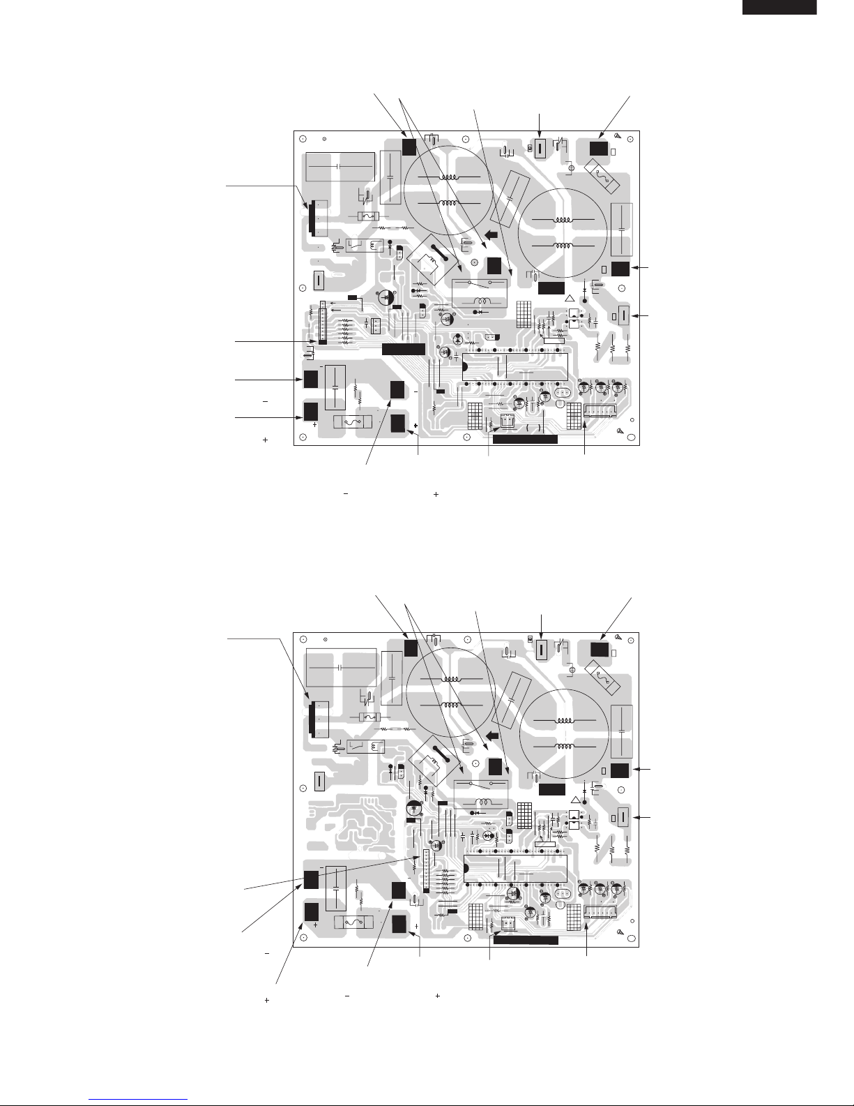
Figure L-5 Printed Wiring Board for AU-S22DP2/S25DP2
Figure L-6 Printed Wiring Board for AU-S32DP2
Page 14
14
AH-S22DP2
AH-S25DP2
AH-S32DP2
FUNCTIONS
1. INDOOR UNIT
1-1 Temperature Adjustment
(1) Cooling
When the room temperature is higher than the preset
temperature by 2˚Cor more, the unit runs at the
maximum operation frequency until the temperature
comes down to the preset temperature.
When reaching the preset temperature, the unit
runs at the frequency calculated by the fuzzy
operation and switches to the normal control.
(2) Dry
After operation begins, 2 minutes of the room
temperature is stored in memory, and that becomes
the set value.
1-2 Indoor fan control
The fan speed can be selected from "Auto", "Soft",
"Low",and "HIgh".When "Soft", "Low" or "HIgh" is
selected, the fanspeed is constant regardless of the
room temperature.When "Auto" is selected, the fan
speed automatically changes between "Soft" and
"HIgh" depending on the difference
between the room and preset temperature.
Control for indoor freezing prevention
If the temperature of the indoor heat exchanger stays
below approximately 1˚C for four minutes during
cooling or dry, this control stops the compressor.
Over 3˚C the compressor will run again.
1-3 Automatic operation
The operating mode and temperature setting are
determined by the room temperature and the external
air temperature.
The operating mode will changeover automatically
with the following condition.
When the set temperature is adjusted within the
range of ±2˚C by the remote control's key. ( ),
Cooling
(24˚C)
(Room temperature
- 2°C)
Cooling
(25˚C)
Cooling
(26˚C)
(Dry)
Room
temperature
(˚C)
29
28 34
Outdoor
temperature (°C)
Cooling
Set temperature
By fuzzy computing
Set the shift up time
Final ( Cooling setting + 1°C)
Dry Same as above
(Final setting + 1°C)
1°C
Stops
Timer set time
1
hour
Timer operation starts
Room
temperature
the changeover judgement room temp. will also be
shifted within the range of ±2˚C.
1-4 ON-timer
The ON-timer is set by pressing the ON-timer button.
In order to attain the set temperature at the set time,
the operation starting time is corrected by fuzzy
computing one hour before the set time.
1-5 OFF-timer
The OFF-timer is set by pressing the OFF-timer
button. Operation is as follows:
*During Cooling / Dry
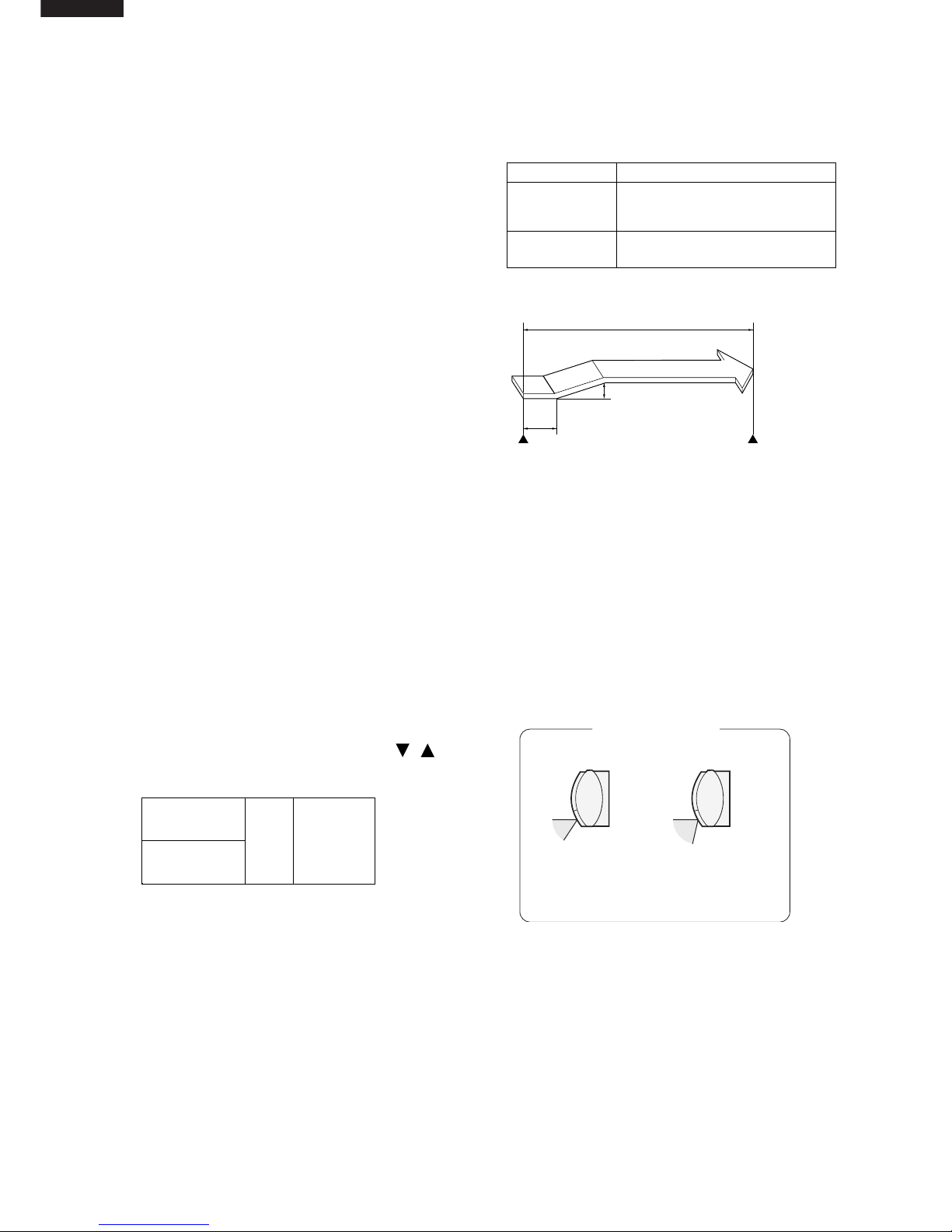
1-6 Swing louvre
The louvre is moved by a stepping motor to perform
swing and fixing in the set position.
If the "FLOW DIRECTION" button is prossed during
swing, it will stop. If the "FLOW DIRECTION" button
is pressed while it is stopped, it will swing.
The vertical adjustment louvre will change its angle
continuously.
Press the SWING button again when the vertical
adjustment louvre is at the desired position.
• The louvre will stop moving within the range shown
in the diagram.
• The adjusted position will be memorized and will
be automatically set to the same position when
operated the next time.
1-7 Restart control
Once the compressor stops, this control prevents it
from starting again for 3 minutes. It also prevents
starting for 80 seconds immediately following plugging
into the power outlet.
1-8 One-hour operation
If this button is pressed when operation is stopped,
operation will begin and then stop after 1 hour. If
pressed when it is operating, will stop after one hour.
1-9 Full power operation
Immediately begins cooling or heating at maximum
power and air flow.
(During cooling) Operates at setting of 18°C.
COOL and DRY modes
FAN ONLY mode
The adjustment range
is narrower the SWING
range in order to prevent condensation from
dripping.
The range is wide so the
air flow can be directed
toward the floor.
Adjustment range
Page 15

15
AH-S22DP2
AH-S25DP2
AH-S32DP2
ON
OFF
ON
ON
Air conditioner
operation
Compressor
relay
100 sec.
ON
OFF
OFF
Air conditioner
operation
Compressor
relay
100 sec.
ON
ON
ON
OFF
ON
OFF
Air conditioner
operation
Compressor
relay
100 sec.
80 sec.
ON
1-10 Power ON start
If a jumper wire is inserted into the place indicated
JP99 on the indoor control board, and the power
plug is inserted. Cooling mode will be automatically
determined by the room temperature sensor on the
main unit, and operation will begin.
1-11 Compressor relay
(1) It is ON during operation, and when operation is
stopped, goes OFF after a delay of 100 seconds
(not immediately).
Power select Cooling
HAH-S32DP2 8.5 A
L 6.7 A
(2) The minimum OFF time of the relay is 80 seconds.
It will not go ON again before 80 seconds elapses.
(3) If air conditioner operation is turned on again
during the 100 second delay before the
compressor relay goes off, the compressor relay
will stay on.
1-12 Power selector [AH-S32DP2]
Operation power "H " (High) or "L" (Low) can be
selected by switching the POWER SELECTOR
slide switch located above the AUX. button.
1-13 Auto Restart
When power failure occures, after power is
recovered, the unit will automatically restart in the
same setting which were active before the power
failure.
Operating mode (Cool, Dry)
Temperature adjustment (within 2˚C range)
automatic operation
Temperature setting
Fan setting
Air flow direction
Power ON/OFF
Automatic operation mode setting
Swing louver
Setting not memorized
Timer setting
Full power setting
1-14 Indoor/outdoor temperature display
Every time the Temperature check button is
pressed on the remote control, the display changes
in the order of indoor temperature outdoor
temperature no display. The temperature is
displayed on the temperature indicator on the main
unit to be referred to for energy saving.
(When the unit is not running, the display changes
between indoor temperature and no display.)Indoor
temperature is the temperature of the suction air
measured by the room thermistor, and outdoor
temperature is that measured by the outdoor
temperature thermistor. When indoor temperature
is displayed, the indoor LED on the main unit is lit,
and when outdoor temperature is displayed, the
outdoor LED is lit. For 90 seconds after the
operation starts, - - is displayed instead of the
actual outdoor temperature since it is still being
measured.Because of the effect of the exchanger,
the unit cannot confirm the exact indoor
temperature right after the operation is terminated.
Therefore, for one hour since the operation is
stopped, the indoor temperature immediately before
the operation is stopped is displayed. After over
one hour since it is stopped, the unit displays the
actual room temperature at that point.
1-15 Error diagnostic display
(a) Indoor unit
(1) When an error is detected, all relays are
turned off. At the same time, the details of the
error are displayed by flashing the number
corresponding to the type of the error. The
details can also be displayed by pressing down
the emergency operation switch for 5 seconds
or more in the state of operation stop.However,
if the operation is continued only in the serial
open state and the state remains unchanged
after that, the main relay is turned off in 8
minutes. In the serial short state, the error is
not displayed and the operation is continued. If
the unit stays in the same state, the main relay
is turned off in 8 minutes. Although the error is
not displayed, it is memorized and can be
displayed when it is recalled.
(2) If the operation is stopped and the emergency
operation button is pressed down for 5 seconds
or more, the self-diagnosis memory can be
recalled.
(3) Details of self-diagnosis (error mode) are
informed by the flashing number as well as the
lighting pattern of the operation lamp which
flashes with the timer lamp.(For details, refer to
Error diagnostic method.)
Page 16

16
AH-S22DP2
AH-S25DP2
AH-S32DP2
2. DESCRIPTION OF ODOR SENSOR
(1) Outline of the odor sensor
The odor sensor is used to cluster display during
operation. This odor sensor sensitively reacts to
the various air contaminations such as a volatile
organic solvent, fragrant materials and tabacco
burning gas. In the figure on the right, RS
indicates a sensor resistance, RL a load
resistance, VRS a sensor output voltage, and
VC a sensor power supply voltage. Their relation
is expressed in the following formula.
When the air contamination level increases, the
value of the sensor resistance RS drops, which
also lowers the value of the sensor output voltage.
While detecting contamination, the microcomputer
outputs the following pulse to the transistor Q8,
which drives the heater with the built-in odor sensor
using the pulse.
Basic circuit
Microcomputer
output
Microcomputer
input
Odor sensor
3
1
2
R
RL
C31
R41
R65
R64
R52
C32
Q7
Q8
R66
5V
S
V
RS
V
C
V
RS = C
R
V
S
R
L + RS
512(µs)
12.8(ms)
Page 17

17
AH-S22DP2
AH-S25DP2
AH-S32DP2
High (85%)
Standard (80%)
Low (75%)
15kΩ
15kΩ 13kΩ
13kΩ
R7 R6
P.W.B.
What to Odor Sensor react to ?
Odor Sensor also may react to vapour of insecticides, cosmetics, alcohol, hemicals and the like, and to extreme change
of temperature / humidity.
(2) Detection of the air contamination by the fluctuation ratio of sensor resistance
The output voltage from the odor sensor is input into the microcomputer to detect the air contamination.
This method detects the air contamination by converting sensor output voltage into the sensor resistance value
and calculating its fluctuation ratio per unit of time. Therefore, the sensor determines that the air is contaminated
when the sensor resistance value drops abruptly.
Clean
Contaminated
Reference value (R0) Smoking start
Determined value K
New reference value (R0)
Additional operation
1 min.
Time
Determined
clean
Determined
contaminated
(3) Operation of the microcomputer
When the air conditioner is power on, the microcomputer starts operating and, after 1 minute, starts detecting the air
contamination.
(4) Switching sensitivity of the odor sensor
The sensitivity of the odor sensor can be adjusted when the sensor is too
responsive or unresponsive.
It is set as standard at the factory.
Sensitivity is divided into three levels: high, standard, and low.
The contamination is detected when the sensor resistance drops below
following percentages compared to the reference value in a clean state.
(This is equal to the description of the resistance of the allergen sensor.)
3. DESCRIPTION OF THE OPTIAL ALLERGEN SENSOR
(1) Outline of the optical allergen sensor
As with the odor sensor, this sensor is used to display cluster during the operation. The pulse signal is output
from the microcomputer into the basic circuit show in the figure below, and the sensor signal is input into the
microcomputer according to the size or amount of the dust.
Output
Output
R39
1
2
3
4
5
6
12V
C29
C30
Q6
R38
R40
R72
Input
Input
60Hz : 16.6 ms
Basic circuit
Allergen
sensor
Page 18

18
AH-S22DP2
AH-S25DP2
AH-S32DP2
Clean
Contaminated
Determined
clean
Determined
contaminated
Reference
value
High (2 sec.)
Med (3 sec.)
Low (4 sec.)
15kΩ
15kΩ 13kΩ
13kΩ
R7 R6
(2) Dust detection by using the sensor
The output voltage from the optical allergen sensor is input into the indoor units microcomputer to detect the air
contamination (dust). This method inputs the sensor voltage per unit of time and calculates the relative fluctuation
to determine whether the air is contaminated or not.
(3) Operation of the indoor unit's microcomputer
As with the odor sensor, the microcomputer starts constantly detecting the air contamination level after 1 minute of
the operation start.
(4) Switching sensitivity of the optical allergen sensor
The sensitivity can be adjusted. However, both sensors will be adjusted
to the same level.
The air contamination is detected in the following seconds at each sensor
level.
ECO
ECO
TIPS ABOUT INDICATOR PANEL
The indicator panel will change each time you press
the DISPLAY button in the following manner.
The room temperature and
POWER MONITOR are displayed.
The outdoor temperature and
POWER MONITOR are displayed.
No display.
POWER MONITOR
When the room temperature or the outdoor temperature is displayed, the POWER MONITOR
will light up in 4 levels for COOL mode (3 levels for DRY mode), to indicate the
operation power. When the air conditioner is operating at maximum power in the COOL
mode, "Power" will light and "Eco" will turn off on the indicator panel.
NOTES:
• The displayed temperatures are rough estimates and may vary from the actual temperatures.
• Temperature display ranges
Room temperature: 0°C ~ 40°C (
is displayed when less than 0°C and when higher
than 40°C)
Outdoor temperature: -9°C ~ 45°C (
is displayed when less than -9°C and when higher
than 45°C)
•
is displayed during the first 90 seconds of operation while the temperatures are being
detected.
• Only the room temperature can be displayed for 5 seconds when the unit is not in operation.
Room Temp.
Lamp
Temperature
Indicator
POWER MONITOR
Outdoor Temp.
Lamp
Page 19

19
AH-S22DP2
AH-S25DP2
AH-S32DP2
• The remote control displays " ".
• The red OPERATION lamp (
) and the blue
PLASMACLUSTER lamp on the unit will light up.
• The unit will stop operation after forty minutes.
• The remaining operation time will be indicated on
the TEMPERATURE INDICATOR of the indoor
unit in minute decrements.
TO CANCEL
Press the SELF CLEAN button.
Or, turn the unit off by pressing the ON/OFF button.
• The red OPERATION lamp (
),the blue
PLASMACLUSTER lamp and the TEMPERATURE
INDICATOR on the unit will turn off.
1
During operation, press the PLASMACLUSTER
button to select the mode.
You can choose PLASMA CLUSTER AUTO OPERATION, AIR CLEAN OPERATION or
REFRESHING OPERATION
PLASMACLUSTER AUTO AIR CLEAN REFRESHING CANCEL
• In the AIR CLEAN operation, the blue
PLASMACLUSTER lamp on the unit will light up.
• In the REFRESHING operation, the green
PLASMACLUSTER lamp on the unit will light up.
TO CANCEL
Press the PLASMACLUSTER button until
PLASMACLUSTER symbol on the remote control
display goes off.
• The PLASMACLUSTER lamp on the unit will turn
off.
NOTE
:
• You cannot set the temperature, fan speed, air flow direction or timer setting during the
SELF CLEAN operation.
NOTES:
• Setting of the PLASMACLUSTER operation will be memorized and will operate in the
same mode, the next time you turn on the air conditioner.
• To turn off the PLASMACLUSTER lamp, press the DISPLAY button.
PLASMA CLUSTER OPERATION
SELF CLEAN OPERATION
Press the SELF CLEAN button when the unit is not
operating.
1
1
1
1h
Page 20

20
AH-S22DP2
AH-S25DP2
AH-S32DP2
The ionizer inside the air conditioner will release cluster ions, which are
collective mass of positive and negative ions, into the room.
The cluster ions reduce airborne mold fungus and deodorize/decompose odorcausing molecules.
AIR CLEAN OPERATION
Cluster ions released into the air will reduce airborne mold fungus and deodorize/decompose
odor-causing molecules.
REFRESHING OPERATION
It is said that plenty of negative ions exist in places such as waterfalls or forests in natural
environment. In this operation mode, negative inos will be released in an increased rate, in order
to bring the room air close to this condition.
PLASMACLUSTER AUTO OPERATION
Dust sensor and odor sensor will detect foul air in the room.
Air Clean Operation will be performed for one minute after the air conditioner is operated to
detect foul air.
Air Clean Operation and Refreshing Operation will be selected and be performed automatically
depending on the air foul degree.
Air Clean Operation will be performed when the air is detected to be foul, Refreshing Operation
will be performed when the air is clean.
SELF CLEAN OPERATION
Plasmacluster Operation will be performed with FAN mode, in order to reduce the
growth of mold fungus, and dry inside of the air conditioner unit.
Utilize the operation at seasonal change over terms.
Mold fungus already grown can not be eliminated by this operation.
TIPS ABOUT DUST SENSOR AND ODOR SENSOR
What does Dust Sensor react to?
• Dust sensor reacts to mold fungus, plants/flowers pollen, dead ticks, dust, tobacco smoke etc.
What does Odor Sensor react to?
• Odor Sensor reacts to tobacco smoke, motor exhaust, odor emitted from animals, etc.
Dust and Odor Sensor also may react to vapour of insecticides, cosmetics, alcohol, chemicals
and the like, and to extreme change of temperature/humidity.
Ionizer
Cluster ions
Mold fungus
Odor
TIP ABOUT PLASMACLUSTER OPERATION
Page 21

21
AH-S22DP2
AH-S25DP2
AH-S32DP2
2. OUTDOOR UNIT
2-1 Frequency control
(1) AC current peak control
(2) Control for prevention of outdoor heat exchanger
overheating. If the temperature of the outdoor heat
exchanger exceeds the overheating prevention line
1 or 2 during cooling, the operating frequency is
lowered by approximately 5 to 15 Hz.
After that, the frequency is lowered by approximately
5Hz once every 60 seconds or approximately 15Hz
once every 120 seconds. When the temperature of
the outdoor heat exchanger goes below the
overheating prevention clear line, the frequency is
raised by approximately 5 Hz once every 60 seconds,
and normal operation is restored. If the frequency is
lowered to minimum frequency without the
temperature of the outdoor heat exchanger
decreasing and this condition lasts for 1 minute, the
compressor will be stopped.
(3) Control for prevention of discharge overheating
If the discharge temperature exceeds approximately
105°C during compressor operation, the operating
frequency is lowered by approximately 5 Hz. After
that, the frequency is lowered by approximately 5 Hz
once every 60 seconds. When the discharge
temperature goes below approximately 104°C , the
frequency is raised by approximately 5 Hz once
every 60 seconds, and normal operation is restored.
If the frequency is lowered to minimum
frequencywithout the discharge temperature
decreasing and this condition lasts for 1 minute, the
compressor will be stopped.
(4) Control for prevention of indoor heat exchanger
freezing
If the temperature of the indoor heat exchanger goes
below approximately 5°C during cooling(only Full
power operation), the operating frequency is lowered
by approximately 5 Hz. After that, the frequency is
lowered by approximately 5 Hz once every 60
seconds. When the temperature of the indoor heat
exchanger rises above approximately 5°C, the
frequency is raised by approximately 5 Hz once
every 60 seconds, and normal operation is restored.
If the temperature of the indoor heat exchanger goes
down to approximately 0°C and this condition
continues for 4 minutes, the compressor is stopped.
When the temperature rises above approximately
2˚C, normal operation is restored.
2-2 Overcurrent protection
(1) Compressor lock detection
If the set value 2.7A of AC current is exceeded in 6
seconds when operation begins, operation is stopped.
In this case, the outdoor fan does not stop, and 170
seconds after operation is stopped, another try will
be made. Three retries are allowed. On the fourth
retry, a complete stop request signal is sent to the
indoor unit, and the outdoor unit will remain stopped
until reset is performed. At this time, the 3-minute
delay for control of the outdoor unit will not function;
therefore, do not cancel by removing the plug and
cutting the power.
(2) DC overcurrent detection, AC overcurrent detection
To protect against overcurrent due to sudden changes
in load, the compressor is stopped if the set value
(AU-S32DP2: 47A, AU-S22DP2/S25DP2: 26A) DC
is exceeded in the DC section, or the set value (AUS22DP2/S25DP2: 11A, AU-S32DP2: 13A) AC is
exceeded in the AC section. In this case, the outdoor
fan does not stop, and 170 seconds after operation is
stopped, another try will be made. Three retries are
allowed. On the fourth retry, a complete stop request
signal is sent to the indoor unit, and the outdoor unit
will remain stopped until reset is performed. At this
time, the 3-minute delay for control of the outdoor
unit will not function; therefore, do not cancel by
removing the plug and cutting the power.
2-3 Compressor protector control
If the temperature of the compressor chamber
exceeds 114°C, the compressor is stopped. In this
case, the outdoor fan does not stop, and when the
compressor chamber temperature decreases to
100°C three minutes after operation is stopped,
another try will be made. Three retries are allowed.
On the fourth retry, a complete stop request signal is
sent to the indoor unit, and the outdoor unit will
remain stopped until reset is performed. At this time,
the 3-minute delay for control of the outdoor unit will
not function; therefore, do not cancel by removing
the plug and cutting the power.
2-4 Power transistor module protector
If the temperature of the chips in the power transistor
module exceeds 105 °C, the compressor is stopped.
In this case, the outdoor fan does not stop, and when
the temperature of the chips in the power transistor
module decreases to 105 °C and 170 seconds
seconds after operation is stopped, another try will
be made.
Three retries are allowed. On the fourth retry, a
complete stop request signal is sent to the indoor
unit, and the outdoor unit will remain stopped until
reset is performed. At this time, the 3-minute delay
for control of the outdoor unit will not function;
therefore, do not cancel by removing the plug and
cutting the power.
2-5 Serial signals
(1) Serial signals consist of all 96-bit signals.
(2) If the outdoor unit does not receive a serial signal, it
will stop approximately 30 seconds later. Note that
this is true only of normal operation; in test mode, it
does not stop and operation takes place based on
the test mode commands.
56˚C
58˚C
55˚C
Lower 5Hz once every 60 seconds
Lower 15Hz once every 120 seconds
Overheating prevention line 1
Overheating prevention line 2
Clear line
Model
Set value
7.5A
6.5A
8.5A
AU-S22DP2
AU-S25DP2
AU-S32DP2
Page 22

22
AH-S22DP2
AH-S25DP2
AH-S32DP2
FUNCTION AND OPERATION OF PROTECTIVE PROCEDURES
Function
NO
Description Detection
time
Restart
condition
Restart
times
Indoor
Outdoor
Operation Self diagnostic
display
1
2
3
4
5
Indoor fan
lock
Indoor fan
rpm error
Indoor
freezing
guard
DC
overcurrent
AC
overcurrent
Compressor
lock
Stops operation if no rotation pulse
signal is input from the indoor fan motor for
one minute.
Stops operation if the rotation pulse
signal from the indoor fan indicates low
rpm (approximately 300 rpm or less).
for 4 minutes.
Lowers the operating frequency if the
temperature of the indoor heat exchanger
goes below 5ϒC during cooling. Stops the
compressor if the temperature stays below
0ϒC for 4 minutes.
Stops the compressor if a current of
approximately 26A or more flows in the
power transistor module. Also stops the
compressor if the temperature of the
power transistor module is exceeds 105ϒC.
Lowers the operating frequency if the
compressor AC current exceeds
set valve( ).Show "2-2(1)AC peak control"
Stops the compressor if the current
exceeds at 40Hz or less set valve.
Stops the compressor if the compressor
AC current exceeds 2.7A immediately after
activating the compressor (in 6 seconds).
When indoor
fan is rotating
During cooling
and dry
During
compressor
operation
During
compressor
operation
Immediately
after
compressor
activation.
Operation OFF
Automatically
restarts when the
exchanger
temperature rises
above the freezing
prevention
temperature (above
2ϒC)
Automatically
restarts after safety
time (170 seconds)
Automatically
restarts after safety
time (170 seconds)
Automatically
restarts after safety
time (170 seconds)
No limit
No limit
4 times
4 times
4 times
Yes
No
Yes
Yes
Yes
No
No
Yes
Yes
Yes
Model
( )
Set value
7.5A
6.5A
8.5A
AU-S22DP2
AU-S25DP2
AU-S32DP2
Page 23

23
AH-S22DP2
AH-S25DP2
AH-S32DP2
Function
NO
Description Detection
time
Restart
condition
Restart
times
Indoor
Outdoor
Operation Self diagnostic
display
6
7
8
9
10
11
12
13
Compressor
overheating
control
Compressor
high
temperature
error
Outdoor heat
exchanger
overheating
control
Outdoor
thermistor
short
Outdoor
thermistor
open
AC abnormal
current error
Serial signal
error
Outdoor
terminal
board
terminal
fuse
operation
Lowers the operating frequency if the
temperature of the compressor chamber
thermistor (TH1) rises above 105ϒC.
Stops the compressor if the thermistor
stays above 105ϒC for 1 minutes at
minimum frequency or less.
Stops the compressor if the compressor
chamber thermistor is above 114ϒC.
(Or when TH1 shorts)
Lowers the operating frequency if the
temperature of the outdoor heat exchanger
rises above 56ϒC during cooling. Stops the
compressor if the temperature stays above
56ϒC for 1 minute at minumum frequency.
Stops the compressor if an outdoor
thermistor (excluding TH1) shorts.
Stops the compressor if the circuit of an
outdoor thermistor breaks.
Stops the compressor if the operating
frequency is above 70 Hz and the
compressor current is below 1.0 A.
Turns the compressor relay off if the indoor
unit does not receive a serial signal from
the outdoor unit for 8 minutes.
Stops the compressor if the outdoor unit
does not receive a serial signal from the
indoor unit for 30 seconds.
Stop operation
The reason that the fuse operation is by
connection eroor at the inside of terminal
board.
During
compressor
operation
During
operation
During
compressor
operation
When
compressor is
activated
When
compressor is
activated
During
compressor
operation
During
operation
During
operation
During
operation
Automatically
restarts after safety
time (170 seconds)
Automatically
restarts when
thermistor (TH1)
temperature falls
below 100ϒC
(approximately 30
minutes)
Automatically
restarts after safety
time (170 seconds)
Automatically
restarts after safety
time (170 seconds)
Automatically
restarts after safety
time (170 seconds)
Automatically
restarts after safety
time (170 seconds)
Automatically
restarts less than 8
minutes after
operation stops
Restarts after
reception of serial
signal
Insert CN9 (short)
No limit
4 times
No limit
4 times
4 times
4 times
No limit
No limit
No
Yes
No
Yes
Yes
Yes
Yes
Yes
No
Yes
No
Yes
Yes
Yes
Yes
Yes
Page 24

24
AH-S22DP2
AH-S25DP2
AH-S32DP2
BREAK DOWN DIAGNOSIS PROCEDURE
Self-diagnostic procedure using display mode. If the timer lamp blinksduringoperation, the problem can be diagnosed using the
following table.
: Blinks at 2-second intervals : OFF : ON : Blinks 3 times at 0.2-second intervals
Indoor and outdoor unit
completely stopped
Display by indoor unit operation lamp
Displayed in a pattern which comes on at the same
time as the timer lamp
4 seconds off
Temp. display
What to check, procedure
Display by
outdoor
unit lamp
LED 1
Diagnosis
Solution
Condition
of indoor
and
outdoor
unit
Normal
Once
Twice
3 times
4 times
5 times
6 times
7 times
Compressor lock error
DC overcurrent error
AC overcurrent error
Normal
Does compressor active ? Does it go off immediately after active ?
1. Check the circuit in the power transistor module.
2. Is the outdoor fan revolving ?
1. Is the discharge outlet of the outdoor unit clogged ?
1. Measure the resistance of thermistor TH2 on the outdoor unit
(see Figure 2).
1. Replace power transistor
module
1. Clear the discharge outlet.
Overheat of the comp-
ressor error
(protector operating) or
outdoor compressor
thermistor TH1 short
1. Replace the outdoor control board
assembly
(Current transformer wire break.)
1. Reattach.
2. Replace the outdoor thermistor
assembly.
1. Replace the outdoor thermistor
assembly.
1. Clear the discharge outlet.
2. Assure power supply voltage.
3. Refill to rated amount.
4. Replace the outdoor ther-mistor
assembly.
5. Replace the indoor control board
assembly or only TH2.
1. Apply an external shock to the
compressor.
2. Replace the compressor.
1. Can voltage be detected at the current transformer on the outdoor
unit control board?
1. Are the connectors of the outdoor unit thermistors well attached ?
2. Measure the resistance of thermistors TH1 and TH2 on the
outdoor unit (see Figure 2).
1. Is the discharge outlet of the outdoor unit clogged ?
2. Is the power supply voltage at least 198 V at full power operation ?
3. Check for refrigerant leaks at the tubing connections.
4. Measure the resistance of compressor thermistor TH1 on the
outdoor unit (see Figure 2).
5. Measure the resistance of heat exchanger pipe thermistor TH2 on
the indoor unit (see Figure 1).
AC abnormal current
error
Open circuit of the
thermistor error
Short circuit of the
thermistor error
1. Retry to connect short wire.
2. Replace the short wire.
10 times
Out terminal board
thermal fuse operation
1. Check the CN9 and short wire.
Page 25

25
AH-S22DP2
AH-S25DP2
AH-S32DP2
Note: 1. Normal : Only the timer lamp blinks. Error : Displayed by blinking of run
lamp (above table).
2. If the power plug is removed from the outlet or the breaker is switched to
"OFF", the self-diagnostic memory will be erased.
3. Example of outdoor unit LED 1 blinking :
: Blinks at 2-second intervals : OFF : ON : Blinks 3 times at 0.2-second intervals
Indoor unit
operating
Outdoor unit
completely stopped
Only recall of self-diagnosis
memory.
Indoor and outdoor units are
not stopped.
Display by indoor unit operation lamp
Displayed in a pattern which comes on at the same
time as the timer lamp
4 seconds off
What to check, procedure
Display by
outdoor
unit lamp
LED 1
Diagnosis
Solution
Condition
of indoor
and
outdoor
unit
Serial short
Serial open
Cluster generator
circuit error
1. Check the wiring between units.
1. Check the wiring between units.
1. Check the wiring between units.
2. Check the fuse in the outdoor unit.
3. Indoor control board.
4. Outdoor control board.
1. Check the wiring between parts.
2 Indoor control board.
3. Hi-voltage unit.
1. Rewire.
2 Replace the control board.
3. Replace the Hi-voltage unit.
1. Rewire.
1. Rewire.
Indoor fan out of order
1. Is the fan motor locked ?
2. Is the wiring connector firmly fitted ?
3. Is the rotation pulse signal applied to the motor ?
Outdoor power supply
does't turn on.
Wiring mistake.
1. Rewire.
2. Replace the fuse, replace the
outdoor board assembly.
3. Replace the control board.
4. Replace the control board.
1. Replace fan motor
2. Reattach.
3. Replace the indoor control board
assembly.
1
sec..
1
sec
0.6
sec.
1
sec.
1
sec.
1
sec.
1
sec.
1
sec.
0.6
sec.
1
sec.
1
sec.
1
sec.
1
sec.
1
sec.
1
sec.
Compressor lock
1
sec.
1
sec.
1
sec.
Overheat of the compressor
0.6
sec.
0.6
sec.
1
sec.
0.6
sec.
1
sec.
0.6
sec.
1 time
2 times
ON
OFFONOFF
Page 26

26
AH-S22DP2
AH-S25DP2
AH-S32DP2
100
80
60
40
20
0
-10 0 10 203040
Resistance
Thermistor
Room temperature
Heat exchange
Color
Yellow
Orange
To measure the resistance, first remove
the connector as shown at right.
Room temperature
thermistor TH1
Tester
Signal
CN7
CN7
Figure 1 Temperature properties of indoor thermistors
500K
400K
300K
200K
100K
0
-20 0 20 60 80 100 120
3.06K5.78K
4.17K 2.28K
1.72K
16
40K
30K
20K
10K
0
-20 0 20 60
40
16
Figure 2 Temperature properties of outdoor thermistors
Connector
CN8
TH2 Heat exchange thermistor
TH3 Outdoor temp. thermistor
TH1 compressor thermistor
TH2,TH3
Connector
CN8
Temperature (ϒC)
Temperature (ϒC)
Tester
Tester
Thermistor To measure the
resistance, first
remove the
connector from the
board.
ColorNo. Connector
Compressor
thermistor
Heat exchanger
pipe thermistor
Outdoor temp.
thermistor
TH1
TH2
TH3
No. 1 to 2
No. 3 to 4
Red
Orange
No. 5 to 6
Green
Microcomputer
terminal
Input
signal
To Outdoor control board
Adaptor
(C14 )
(GND)
(R17)
Pin No. 43
Pin No. 42
0
1
0 Low input
1 High input
K
Heat exchange thermistor
TH2 (orange)
25ϒC resistance 15 K
Room temperature
thermistor TH1 (yellow)
25ϒC resistance 10 K
25ϒC resistance
45 K
Resistance ( )
Resistance ( )
0ϒC resistance
14.5 K
25ϒC resistance
4.431 K
Heat exchange
thermistor TH2
Tester
41
Cautions when attaching or removing the board
When operating only the outdoor unit (cooling 40 Hz fixed mode) To make
only the outdoor unit run in cooling mode, short the places marked with
arrows below with an adaptor, and apply a voltage of 220 ~ 240 V AC to 1
and N on the terminal board.
(Avoid operating the outdoor unit alone for long periods of time.)
PC1
PC2
R6
R5
R7
R16
R17
C14
Cool / 40Hz
3
4
1
2
Page 27

27
AH-S22DP2
AH-S25DP2
AH-S32DP2
1
2
Capillary tube
3
Outdoor unit
Condenser
Evaporator
Indoor unit
Compressor
Flare coupling Flare coupling
Silencer
4
3-way
valve
2-way
valve
Accumulator
Indoor side
Standard conditions:
AH-S22DP2/S25DP2/S32DP2
Dry-bulb Temp. (˚C) Relative Humidity (%)
27Cooling 47
Outdoor side
Dry-bulb Temp. (˚C) Relative Humidity (%)
35 40
Temperature at each part and pressure in 3-way valve
Operation
mode
Model
Cool
(Max.)
1
2
3
4
3-way valve
pressure
(MPaG)
85˚C
40˚C
12˚C
5˚C
0.44
89
95˚C
38˚C
12˚C
8˚C
0.45
101
83˚C
42˚C
14˚C
5˚C
0.46
97
68˚C
40˚C
13˚C
7˚C
0.55
60 settle
68˚C
42˚C
15˚C
9˚C
0.60
60 settle
Cool
Cool
(Max.)
Cool
Cool
(Max.)
Cool
68˚C
41˚C
14˚C
8˚C
0.63
60 settle
No.
Hz
Dimension of Capillary tube
AH-S22DP2
AH-S25DP2
AH-S32DP2
Model
ø2.7
ø2.7 ø2.7
O.D
ø1.5 ø1.5
ø1.6
600
600
I.D L
O.D
I.D L
O.D
I.D L
300
Capillary tube
AH-S25DP2AH-S22DP2 AH-S32DP2
REFRIGERATION CYCLE
Figure R-1. Refrigeration Cycle
Page 28

28
AH-S22DP2
AH-S25DP2
AH-S32DP2
PERFORMANCE CURVES
NOTE: 1) Indoor fan speed: Hi, Thermostat setting : 18˚C
2) Vertical adjustment louver "45˚", Horizontal adjustment louver "front"
3) Indoor air temp. : D.B. 27˚C, W.B. 19˚C (RH47%)
Figure P-1. At Cooling for AH-S22DP2
25 30 35 40
2.5
2.7
2.9
3.1
10
12
14
800
1000
1200
1400
(Running frequency: 101Hz)
Cooling capacity(kW)
Outside air temp.(˚C)
Input(W)
Outlet air temp.(˚C)
Figure P-2. At Cooling for AH-S25DP2
Figure P-3. At Cooling for AH-S32DP2
25 30 35 40
2.5
2.7
2.9
3.1
10
12
14
600
800
1000
1200
Cooling capacity(kW)
Outside air temp.(˚C)
Input(W)
Outlet air temp.(˚C)
(Running frequency: 89Hz)
25 30 35 40
3.6
3.8
4.0
4.2
10
12
14
1000
1200
1400
1600
Cooling capacity(kW)
Outside air temp.(˚C)
Input(W)
Outlet air temp.(˚C)
(Running frequency: 97Hz)
Page 29

29
AH-S22DP2
AH-S25DP2
AH-S32DP2
DISASSEMBLING PROCEDURE
FOR INDOOR UNIT [AH-S22DP2/S25DP2/S32DP2]
CAUTION : DISCONNECT THE UNIT FROM THE POWER SUPPLY BEFORE ANY SERVICING
1. Open the opne panel, and remove 2 air filters.
2. Remove 4 screws fixing the front panel.
3. Remove the screw fixing the cord clamp.
Note: During reassembly, install the holder after
installing the front panel. This will make it
easier to assemble the front panel.
4. Close the open panel. Pushing the nail of the front
panel.
5. Pull the front panel up.
6. Remove the unit-to-unit wiring from the terminal
board.
7. Remove a screw fixing the control box cover, and
remove it.
8. Remove a screw fixing the ground wire.
Note: During reassembly, take care for the
direction of the lead wire.
Page 30

30
AH-S22DP2
AH-S25DP2
AH-S32DP2
9. Remove the thermistor of the evaporator.
10. Remove 4 connectors.
11. Remove the thermistor holder from the evaporator.
12. Remove the display from the drain pan.
13. Remove the screw fixing the pipe holder.
14. Remove 3 screws fixing the control box, and remove
the control box.
15. Remove a screw fixing the drain pan.
16. Pull drain pan toward you.
CN1
CN6
CN3
CN2
Page 31

31
AH-S22DP2
AH-S25DP2
AH-S32DP2
17. Remove the drain cover from the evaporator.
Note: During reassembly, verify that the dew on
the pipe is led to the drain pan.
18. Remove 4 screws fixing the evaporator.
19. Remove the evaporator from the cabinet.
20. Remove 2 screws fixing the motor cover, and pull up
the fan.
21. Loose a screw fixing fan.
[Cautionary points for assembling the fan]
a. When inserting the motor shaft into the metal fan
boss, take care to prevent injuring the inner surface of
the metal fan boss.
b. Before fastening the motor shaft and fan, insert the
motor shaft into contact with the bottom of the metal
fan boss.
Fan motor
Motor shaft
Fan boss
Cross flow fan
Page 32

32
AH-S22DP2
AH-S25DP2
AH-S32DP2
How to remove the display cover
1. Push the center of display cover from the back.
2. Slide the display cover to the right.
How to assemble the display cover
1. Slide the left end of the display cover through 3 hooks
on the front panel along the guide from the center of
the front panel.
2. After the left half is inseted completely, press the
display cover and snap in the 3 hooks on the right.
How to remove the control box
2. Remove the screw fixing the terminal board.
1
2
1. Remove the photo detector unit.
(Press and spread the upper hook, and the photo
detector unit will be ready for removal.)
3. Remove a screw fixing the cord holder.
4. Remove 2 screws fixing the board (transformer).
5. Remove 5 connectors. And cut off a fixing band.
CN8 CN10
CN6
CN9
CN7
Page 33

33
AH-S22DP2
AH-S25DP2
AH-S32DP2
DUST SENSOR
GAS SENSOR
THERMISTOR
CN101 and CN102
6. Remove 2 connectors.
7. Pull the board.
Drain pan and related
1. Remove 3 screws fixing motors.
2. Turn the cap area of the drain hose counterclockwise,
and remove it from the drain pan.
During installation, turn the drain hose to the state of
the “engagement position”.
After reinstallation, verify that it is securely fastened.
How to remove the horizontal louver
Slightly pull down the hinge area, deflect the louver, and
unhook it from the hinge. Remove the shaft from each of
the left and right sides.
Drain pan
Drain Hose
Groove
Projection
To disconned To reconnect
How to remove the HI VOLTAGE UNIT.
1. Remove the HIGH VOLTAGE UNIT.
(Press and spread the hook, and HI VOLTAGE will
be ready for removal.)
How to remove the DUST SENSOR, the THERMISTOR
and the GAS SENSOR.
Remove the DUST SENSOR, the THERMISTOR, and
the GAS SENSOR.
(Press and spread the hook,and GAS SENSOR will be
ready for removal)
How to remove the display board unit 2.
The display board unit 2 is pushed in the direction of
arrow 1 .
And it is made to slide in the direction of arrow 2 , and
remove.
display board unit2
1
2
Page 34

34
AH-S22DP2
AH-S25DP2
AH-S32DP2
FOR OUTDOOR UNIT [AU-S22DP2/S25DP2/S32DP2]
CAUTION : DISCONNECT THE UNIT FROM THE POWER SUPPLY BEFORE ANY SERVICING
1. Loose a screw fixing the side cover.
2. Loose the unit to unit cord.
3. Loose a screw fixing the cord clamp.
4. Loose 4 screws fixing the top panel.
5. Loose 6 screws fixing the front panel.
6. Cut 2 nylon bands.
7. Disconnect terminals as following.
Reactor (2 terminals)
Fan motor
Thermistor
Right side view Left side view
Right side view Left side view
Front view
Page 35

35
AH-S22DP2
AH-S25DP2
AH-S32DP2
8. Remove the terminal cover of compressor.
9. Disconnect 3 terminals.
10. Loose 4 screws fixing the control box.
11. Take out the control box.
DISASSEMBLING PROCEDURE OF THE FAN
1. Loose the fan nut and fan can take out.
2. Fan motor is secured by 4 screws.
Loose
Page 36

36
AH-S22DP2
AH-S25DP2
AH-S32DP2
OPTION
1
Take out the air filters.
Open the open panel.
Push the air filters up slightly to unlock
them.
Pull the air filters down to remove
Take of the old dust collection filter
and the deodorant filter from the air filter.
Snap out in the arrow marked direction.
Set the new dust collection filter and
the deodorant filter with filter stoperts
located on the air filters.
them.
2
Check the filters.
3
Reinstall the air filters
Reinstall the air filters in the original
positions.
Close the open panel.
Push the arrow-marked of the panel
firmly to lock it in place.
DUST COLLECTION FILTER (gray)
Set the black side facing upward.
Filter stopper
DEODORANT FILTER (green)
Filter stopper
2
1
3
3
1
2
HOW TO REPLACE THE
DUST COLLECTION FILTER AND DEODORANT FILTER
Precautions
The dust collection filter and the deodorant filter are packed as accessory of this unit.
During operation of the air conditioner, the filters remove dust and tobacco smoke
from the air and discharges clean air.
• The filters are sealed in a plastic bag to keep their dust collection effect.
Do not open the bag until using the filters. (Otherwise the filters life may get shorter.)
• Do not expose the filters to direct sunlight. (Otherwise they may deteriorate.)
1
3
2
1
1
3
2
2
Page 37

37
AH-S22DP2
AH-S25DP2
AH-S32DP2
CLEANING THE DEODORANT FILTER (GREEN)
The filter should be cleaned every 3~6 months
1
REMOVE THE AIR FILTERS
2
CLEAN THE DEODORANT FILTER
1 Take off the deodorant filter from the air
filters.
2 Soak the deodorant filter in mild detergent
dilution for 10 to 20 minutes.
Rinse thoroughly with water, dry completely
under sunlight.
3 Set the clean deodorant filter under the fil-
ter stoppers located on the air filters.
3
REINSTALL THE AIR FILTERS
NOTE
:
• Replacement is necessary at the interval of 3 years, as the deodorising effect will
deteriorate.
The new filters are available at your nearest dealer.
Replacement filter: Type AZ-F910C
CHANGING THE DUST COLLECTION FILTER (GRAY)
The filter should be changed every 3~6 months
1
REMOVE THE AIR FILTERS
2
CHANGE THE DUST COLLECTION FILTER
1 Take off the old dust collection filter from
the air filters.
2 Set the new dust collection filter, the black
side facing upward, under the filter stoppers located on the air filters.
3
REINSTALL THE AIR FILTERS
NOTE
:
• The dirty dust collection filter is not washable for reuse.
The new filters are available at your nearest dealer.
Replacement filter: Type AZ-F900C
Filter stopper
Filter stopper
Page 38

38
AH-S22DP2
AH-S25DP2
AH-S32DP2
REF. NO. PART NO. DESCRIPTION Q'TY CODE
REPLACEMENT PARTS LIST [AH-S22DP2/AH-S25DP2/AH-S32DP2]
CABINET AND UNIT PARTS
1- 1 CMOT-A389JBKZ Fan motor sub ass’y 1 BG
1- 2 PGUMSA046JBE0 Damper rubber 1 AD
1- 3 CHLD-A067JBK0 Bearing ass’y 1 AL
1- 4 DCHS-A399JBKZ Cabinet sub ass’y [AH-S22DP2/AH-S25DP2] 1 BD
1- 4 DCHS-A401JBKZ Cabinet sub ass’y [AH-S32DP2] 1 BC
1- 5 NFANCA089JBEZ Cross flow fan 1 BD
1- 6 DSRA-A246JBKZ Drain pan sub ass’y 1 BE
1- 7 CMOTLA901JBEZ Fan motor 1 BK
1- 8 MJNTPA082JBFA Louver link 2 AC
1- 9 MLOV-A299JBFA Vertical louver 12 AC
1-10 MLOV-A334JBRA Horizontal louver A 1 AM
1-11 MLOV-A298JBFA Horizontal louver B 1 AK
1-12 QW-VZC406JBE0 Lead wire (for Fan motor) 1 AK
1-13 LHLD-A197JBFP Louver holder 2 AX
1-14 NBRG-A026JBFA Louver bushing 2 AB
1-15 LHLD-A561JBFA Holder 1 AM
1-16 PHOS-A025JBE0 Drain hose 1 AL
1-17 PPACGA010JBE0 O ring 1 AB
1-18 PGID-A097JBFZ Drain cover 2 AF
1-19 RMOT-A061JBE0 Louver motor 2 AS
1-20 PGUMMA110JBE0 Drain plug 1 AD
1-21 CWAK-C323JBKZ Front panel ass’y 1 BC
1-22 PPLT-A212JBFZ Side cover R 1 AL
1-23 PPLT-A213JBFZ Side cover L 1 AL
1-24 PCOV-A764JBRA Display cover 1 BB
1-25 PFILMA145JBEA Air filter 2 AL
1-26 DHLD-A010JBKZ Tube holder ass’y 1 AK
1-27 HPNL-A514JBTA Open panel 1 AQ
1-28 TSPC-E3896JBRA Name label [AH-S22DP2] 1 AE
1-28 TSPC-E388JBRA Name label [AH-S25DP2] 1 AE
1-28 TSPC-E389JBRA Name label [AH-S32DP2] 1 AE
1-29 PFPFPB901JBEZ Cabinet insulator [AH-S22DP2/AH-S25DP2] 1 AH
1-30 QW-VZE013JBZZ Lead wire (for Louver motor:Upper) 1 AG
1-31 GWAK-A271JBFA Front panel 1 AV
1-32 PCOV-A614JBFZ Drain cover 1 AG
1-33 TLABCB794JBRZ Wiring diagram 1 AF
1-34 QW-VZD893JBZZ Lead wire (for Louver motor:Lower) 1 AG
1-35 LHLD-A303JBFA Tube cover 1 AD
1-36 PSEL-C125JBEZ Panel insulator 1 AF
1-37 PFPFPB971JBEZ Sheet 1 AA
1-38 PSPA-A154JBEZ Rubber spacer 1 AD
1-39 PSHE-A126JBE0 Evaporator seal 1 AG
1-40 LSPR-A007JBE0 Sheet spring 2 AD
1-41 LHLD-A536JBFA Holder 1 AM
1-42 PFPFPB962JBEZ Sidecover insulator 1 AC
1-43 PFPFPB967JBEZ Insulator 1 AC
1-44 HDEC-B147JBEA Display panel 1 AQ
1-45 PSEL-C055JBEZ Evaporator seal 1 AC
1-46 PSEL-C136JBEZ Insulator [AH-S32DP2] 1 AC
1-47 PSEL-C294JBEZ Aluminum tape 1 AC
1-48 TLAB-C356JBRZ Filter label 1 AC
1-49 DCOV-A206JBKZ Cover ass’y 1 AE
1-50 PCOV-A821JBEZ Lead cover A 1 AC
1-51 PCOV-A822JBEZ Lead cover B 1 AC
CONTROL BOX
2- 1 RTHM-A300JBE0 Thermistor 1 AP
2- 2 PBOX-A342JBFZ Control box 1 AQ
2- 3 PBOX-A341JBFZ Terminal cover 1 AH
2- 4 VSKRA105M//-3 Transistor (Q1, Q2,Q10) 3 AB
2- 5 VS2SA1585SQR3 Transistor (Q8) 1 AD
2- 6 HPNLCA776JBFA Control box cover 1 AG
2- 7 HPNLCA790JBEA Control panel 1 AD
2- 8 PCOV-A618JBFB Led holder 1 AE
2- 9 PCOV-A766JBFA Led holder B 1 AE
2-10 DPWBFA301JBKZ Control board unit [AH-S22DP2] 1 BR
2-10 DPWBFA302JBKZ Control board unit [AH-S25DP2] 1 BR
2-10 DPWBFA303JBKZ Control board unit [AH-S32DP2] 1 BR
2-11 QACC-A161JBE0 Power supply cord 2 AX
2-12 QTANZA006JBEZ Terminal board (3PIN) 1 AN
2-13 QTANZA001JBZZ Terminal board (4PIN) 1 AQ
2-14 PCOV-A609JBWZ Control box cover 1 AC
2-15 RIC—-A025BDE0 IC (IC4, IC5) 2 AE
Page 39

39
AH-S22DP2
AH-S25DP2
AH-S32DP2
REF. NO. PART NO. DESCRIPTION Q'TY CODE
2-16 VHPGL6ZS27+-6 LED (LED102) 1 AG
2-17 VHPSL326422-6 LED (LED121) 1 AP
2-18 PCOV-A611JBWZ Control box cover 1 AF
2-19 PCOV-A610JBWZ Terminal cover 1 AE
2-20 RRMCUA001JBZZ Photo detector unit (IC201) 1 AK
2-21 QFS-GA053JBZZ Fuse 2.5A 250V (WPE1) 1 AE
2-22 VHIKID65783-1 IC (IC6) 1 AK
2-23 RIC—-A022BDE0 IC (IC3) 1 AE
2-24 VHIBR24C01A-6 IC (IC8) 1 AF
2-25 RH-TZA098JBE0 Transistor (Q3 - Q7, Q9) 6 AB
2-26 RC-HZA463JBZZ Fan motor capacitor (C1) 1 AP
2-27 RH-VXA002JBZZ Varistor (NR1) 1 AF
2-28 RH-IZA149JBE0 IC (IC2) 1 AE
2-29 VHPGL6ZE27+-6 LED (LED103 - LED111) 9 AG
2-30 RTRN-A287JBZZ Transformer (TR1) 1 AT
2-31 VHPGL6ZR27+-6 LED (LED101) 1 AF
2-32 VHRPC817X7/1B Photo coupler (PC1) 1 AD
2-33 VHRPC853H//-6 Photo coupler (PC2) 1 AG
2-34 VHRS201D01/-6 Solid state relay (SSR1) 1 AK
2-35 VHD1SR139-6-1 Diode (D6, D8, D9) 3 AB
2-36 VHD1SR35-4A-1 Diode (D1- D5) 5 AC
2-37 VHEHZ24-2//-1 Zener diode (ZD1) 1 AB
2-38 RH-IZA140JBE0 IC (IC7) 1 AE
2-39 RDTC-A001KKE0 Gas sensor (GS1) 1 AW
2-40 VHRPR33MF11-6 Solid state relay (SSR2) 1 AX
2-41 VHPGL5BG502-1 LED (LED131) 1 AR
2-42 RSNSZA001JBZZ Dust sensor 1 BD
2-43 PFPFPB970JBEZ Sheet 1 AA
2-44 LHLD-A540JBFA Holder 1 AM
2-45 LHLD-A550JBRA Display cover 1 BE
2-46 LHLD-A560JBFA Sensor holder 1 AM
2-47 LHLD-A562JBFA Holder 1 AM
2-48 RH-IXA735JBZZ Integrated circuit (Micro computer IC1) 1 AU
2-49 CKITTA002JBKZ Hi voltage unit ass'y 1 BA
CYCLE PARTS
3- 1 CPIPCA678JBKZ Tube ass’y [AH-S22DP2/AH-S25DP2] 1 BG
3- 1 CPIPCA679JBKZ Tube ass’y [AH-S32DP2] 1 BH
3- 2 PSEN-A005JBKZ Flare nut ass’y (1/4") 1 AG
3- 3 PSEN-A004JBKZ Flare nut ass’y (3/8") [AH-S22DP2/AH-S25DP2] 1 AE
3- 3 PSEN-A016JBKZ Flare nut ass’y (1/2") [AH-S32DP2] 1 AR
3- 4 PVLV-0341JBE0 Flare Union (1/4") 1 AG
3- 5 PVLV-0342JBE0 Flare Union (3/8") [AH-S22DP2/AH-S25DP2] 1 AH
3- 5 PVLV-0406JBE0 Flare Union (1/2") [AH-S32DP2] 1 AK
3- 6 DEVA-A123JBKZ Evaporator sub ass’y [AH-S22DP2] 1 BR
3- 6 DEVA-A121JBKZ Evaporator sub ass’y [AH-S25DP2] 1 BS
3- 6 DEVA-A122JBKZ Evaporator sub ass’y [AH-S32DP2] 1 BT
ACCESSORY PARTS
4- 1 CRMC-A605JBEZ Remote control 1 BC
4- 2 UBATUA027JBE0 Battery pack 1 AE
4- 3 LHLD-A477JBFA Cord holder
(for covering the terminal board of indoor unit)
1AE
4- 4 XTTSD40P16000 Tapping Screw (for fixing the cord holder) 1 AA
4- 5 LX-NZA207JBEZ Special nut (for fixing long screw steadily) 10 AE
4- 6 PPLTNA058JBWZ Mounting angle 1 AS
4- 7 XTTSD45P30000 Long screw 8 AA
4- 8 XTTSF40P20000 Tapping Screw (for fixing remote control holder) 1 AB
4- 9 LHLD-A484JBFA Holder 1 AE
4-10 GLEGGA008JBE0 Compressor cushion 4 AE
4-11 TINS-A764JBRZ Operation manual 1 AE
4-12 TINS-A765JBRZ Installation manual 1 AC
4-13 TGANJB554JBRZ Warranty card 1 AF
SCREW
5- 1 LX-BZA075JBE0 Special screw (for earth) 1 AA
PACKING PARTS
6- 1 CPADBA038JBKZ Packing Pad Ass’y 2 AK
6- 2 SPAKCB310JBEZ Packing case [AH-S22DP2] 1 AQ
6- 2 SPAKCB312JBEZ Packing case [AH-S25DP2] 1 AR
6- 2 SPAKCB313JBEZ Packing case [AH-S32DP2] 1 AQ
Page 40

40
AH-S22DP2
AH-S25DP2
AH-S32DP2
A
B
C
D
E
F
G
H
A
123456
123456
B
C
D
E
F
G
H
INDOOR UNIT FOR AH-S22DP2/AH-S25DP2/AH-S32DP2
4-1
4-2
1-35
1-23
1-43
3-6
1-45
1-40
1-39
1-46
1-40
1-18
1-5
1-4
1-29
1-3
1-26
4-6
1-22
1-1
1-12
1-32
1-2
1-50
1-51
2-1
3-1
2-53
2-57
3-2
3-5
3-3
3-4
5-1
1-38
1-7
2-13
2-2
2-18
2-14
1-21
4-3
4-4
2-6
2-8
2-7
1-16
1-30
1-19
1-19
1-13
1-20
1-14
2-54
1-37
1-13
1-11
1-17
1-10
1-6
1-27
6-1
6-2
1-24
1-25
1-47
1-31
1-44
1-15
1-28
1-33
1-36
1-25
2-10
2-43
1-42
1-34
1-8
2-58
2-56
2-49
1-49
2-9
1-8
1-9
1-9
1-41
2-55
4-7
4-5 4-8
2-3
2-19
2-12
2-11
4-13
4-12
4-9
4-11
4-10
1-48
Page 41

41
AH-S22DP2
AH-S25DP2
AH-S32DP2
REPLACEMENT PARTS LIST [AU-S22DP2/AU-S25DP2/AU-S32DP2]
REF. NO. PART NO. DESCRIPTION Q'TY CODE
CONTROL BOX PARTS
1- 1 CMOTLA902JBEZ Fan motor [AU-S22DP2/S25DP2] 1 BK
1- 1 CMOTLA903JBEZ Fan motor [AU-S32DP2] 1 BL
1- 2 RTRN-A256JBE0 Current transfoemer CT1 1 AG
1- 3 QW-VZD863JBZZ Lead wire (Bulkhead - TBE) 1 AF
1- 4 DPWBFA219JBKZ Electric control board [AU-S22DP2/S25DP2] 1 BQ
1- 4 DPWBFA222JBKZ Electric control board [AU-S32DP2] 1 BR
1- 5 QTANZA001JBZZ Terminal board (4P) 1 AQ
1- 6 RIC--A022BDE0 Integrated circuit IC2 [AU-S22DP2/S25DP2] 1 AE
1- 7 VSKRC245M//-3 Transistor Q3 1 AC
1- 8 VHRPC817X7/1B Photo coupler PC1 1 AE
1- 9 VHRPC853H//-6 Photo coupler PC2 1 AG
1-10 RC-AZA046JBE0 Capacitor [AU-S22DP2/S25DP2] 1 BE
1-10 RC-AZA071JBE0 Capacitor [AU-S32DP2] 1 BD
1-11 RH-DZA117JBE0 Diode bridge [AU-S22DP2/S25DP2] 2 AM
1-11 VHDD25VB60+-1 Diode bridge [AU-S32DP2] 2 AQ
1-12 RH-QXA004JBZZ PTC thermistor 1 AN
1-13 RH-TZA146JBE0 Power transistor module(IPM)[AU-S22DP2/S25DP2] 1 BS
1-13 RH-TZA152JBZZ Power transistor module(IPM)[AU-S32DP2] 1 BY
1-14 PDAI-A126JBWZ Terminal plate 1 AE
1-15 PSEL-C122JBEZ Insulator 1 AC
1-16 RTHM-A022JBE0 Compressor thermistor 1 AN
1-17 RH-IHA010JBZZ Thermistor 1 AX
1-18 RTRN-A195JBE0 Reactor [AU-S22DP2/S25DP2] 1 BA
1-18 RTRN-A230JBE0 Reactor [AU-S32DP2] 1 BB
1-19 DBOX-A030JBYZ Control box assembly 1 AT
1-20 LBND-A042JBE0 Wire fixing band 4 AC
1-21 PSPA-A151JBZZ Spacer 5 AE
1-22 LHLD-A479JBFZ Heat sink holder 1 AE
1-23 PRDAFA152JBEZ Heat sink for powertransistor module 2 AX
1-24 PSEL-C123JBEZ Insulator 1 AC
1-25 PSHE-A190JBEZ Protect sheet 1 AL
1-26 PSEL-C061JBEZ Insulator 1 AE
1-27 PSPA-A144JBE0 Spacer 2 AC
1-28 RFIL-A064JBE0 Ferrite core 4 AF
1-29 QW-VZD858JBZZ Lead wire (T6 - PTC1) 1 AE
1-30 QW-VZE011JBZZ Lead wire (L1 - T6) 1 AF
1-31 QW-VZD857JBZZ Lead wire (Earth) 1 AC
1-32 QW-VZD868JBZZ Lead wire (MRY1 - DB1~) 1 AG
1-33 QW-VZD861JBZZ Lead wire (MRY1 - PTC) 1 AF
1-34 QW-VZD949JBZZ Lead wire (DB1--C8-) 1 AE
1-35 QW-VZD866JBZZ Lead wire (T3 - TB2) 1 AF
1-36 QW-VZD873JBZZ Lead wire (T10 - IPM(-)) 1 AF
1-37 QW-VZD867JBZZ Lead wire (T5 - DB1)) 1 AG
1-38 QW-VZD864JBZZ Lead wire (T2 - TBN) 1 AF
1-39 QW-VZD865JBZZ Lead wire (T1 - TB1) 1 AF
1-40 QW-VZD859JBZZ Lead wire (C8(+) - T7) 1 AE
1-41 QW-VZD950JBZZ Lead wire (DB1+-C8-) 1 AG
1-42 QW-VZD951JBZZ Lead wire (DB2~-C6) 1 AH
1-43 QW-VZD953JBZZ Lead wire (DB2+-L1) 1 AG
1-44 QW-VZD860JBZZ Lead wire (C8(-) - T8) 1 AE
1-45 QW-VZD872JBZZ Lead wire (T9 - IPM(+)) 1 AE
1-46 QW-IZA017JBZZ Lead wire (Compressor wire) [AU-S22DP2/S25DP2] 1 AP
1-46 QW-IZA019JBZZ Lead wire (Compressor wire) [AU-S32DP2] 1 AP
1-47 PSEL-C124JBEZ Insulator 1 AC
1-48 RH-IXA726JBZZ Microcomputer IC1 1 AW
1-49 RH-IZA140JBE0 Integrated circuit IC3 1 AE
1-50 RH-TZA098JBE0 Transistor Q1 1 AB
1-51 RH-VZA020JBE0 Varistor CNR1 1 AB
1-52 RH-VXA002JBZZ Varistor NR1, NR2 2 AD
1-53 QSPGCA003JBZZ Surge absorber SA1 1 AH
1-54 LBNDKA099JBWZ Capacitor clamp 1 AS
1-55 LBNDKA062JBWZ Capacitor clamp 1 AD
1-56 RC-HZA375JBE0 Capacitor [AU-S22DP2/S25DP2] 1 BA
1-56 RC-HZA426JBZZ Capacitor [AU-S32DP2] 1 BE
CABINET AND UNIT PARTS
2- 1 LANGKA124JBPZ Fan motor angle 1 AR
2- 2 LANGKA128JBPZ Fan motor angle sub [AU-S22DP2/S25DP2] 1 AG
2- 2 LANGKA127JBPZ Fan motor angle sub [AU-S32DP2] 1 AE
2- 3 GCAB-A196JBTA Rear cabinet [AU-S22DP2/S25DP2] 1 BD
2- 3 GCAB-A203JBTA Rear cabinet [AU-S32DP2] 1 BC
2- 4 LHLD-A573JBFA Cord clamp 1 AC
Page 42

42
AH-S22DP2
AH-S25DP2
AH-S32DP2
2- 5 PFPFPB911JBEZ Motor angle cushion 1 AC
2- 6 GCAB-A195JBTA Front panel 1 BC
2- 7 GGADFA037JBFA Fan guard 1 AT
2- 8 PSEL-C045JBEZ Motor angle cushion 1 AB
2- 9 PSEL-C048JBEZ F panel insulator 1 AC
2-10 PSEL-C049JBEZ F panel insulator 1 AC
2-11 PSEL-C050JBEZ Bulkhead insulator 1 AG
2-12 TLABBA148JBRA Sharp badge 1 AH
2-13 CCHS-A735JBTA Base pan assembly [AU-S32DP2] 1 BD
2-13 CCHS-A739JBTA Base pan assembly [AU-S22DP2/S25DP2] 1 BD
2-14 PFTA-A092JBFA Side cover 1 AQ
2-15 PCOV-A616JBPZ Protect cover 1 AE
2-16 MSPR-A027JBE0 Thermistor spring [AU-S22DP2] 1 AB
2-16 MSPR-A026JBE0 Thermistor spring [AU-S22DP2] 1 AB
2-17 MSPR-A046JBE0 Protector spring [AU-S32DP2] 1 AC
2-17 MSPR-A066JBE0 Protector spring [AU-S22DP2/S25DP2] 1 AD
2-18 NFANPA094JBEZ Propeller fan 1 AX
2-19 DSKR-A102JBYZ Bulkhead spot ass'y [AU-S22DP2/S25DP2] 1 AR
2-19 DSKR-A101JBYZ Bulkhead spot ass'y [AU-S32DP2] 1 AS
2-20 TLABKD294JBEZ Number card [AU-S22DP2] 1 AC
2-20 TLABKD295JBEZ Number card [AU-S25DP2] 1 AC
2-20 TLABKD296JBEZ Number card [AU-S32DP2] 1 AC
2-21 TSPC-E390JBRZ Name badge [AU-S22DP2] 1 AE
2-21 TSPC-E391JBRZ Name badge [AU-S25DP2] 1 AE
2-21 TSPC-E392JBRZ Name badge [AU-S32DP2] 1 AE
2-22 PSEL-C051JBEZ Side cover seal 1 AE
2-23 FFTA-A014JBKZ Side cover assembly 1 AT
2-24 TLABCB728JBRZ Wiring diagram [AU-S22DP2/S25DP2] 1 AE
2-24 TLABCB731JBRZ Wiring diagram [AU-S32DP2] 1 AE
2-25 DCAB-A141JBKZ Top cover assembly 1 AZ
2-26 PSEL-C060JBEZ Insulator for rear cabinet 1 AB
2-27 GCAB-A197JBTA Top cover 1 AX
2-28 PCOV-A617JBFA Reactor cover 1 AE
2-29 PSEL-C046JBEZ Bulkhead insulator [AU-S22DP2/S25DP2] 1 AC
2-29 PSEL-C091JBEZ Bulkhead insulator [AU-S32DP2] 1 AE
2-30 PSEL-C119JBEZ Box insulator 1 AE
2-31 PSEL-C047JBEZ Box insulator 1 AF
2-32 PSEL-C062JBEZ Box insulator 1 AG
2-33 CHLD-A093JBK0 Holder assembly 1 AL
2-34 PSEL-C121JBEZ Side cover seal 1 AC
2-35 PSEL-C120JBEZ Side cover seal 1 AC
2-36 JHNDPA011JBFA Holder 1 AS
2-37 LPLTPA026JBFA Cord clamp plate 1 AC
CYCLE PARTS
3- 1 PSPF-A797JBEZ Compressor cover 1 AM
3- 2 DCPY-A219JBKZ Capillary tube assembly [AU-S22DP2/S25DP2] 1 BE
3- 2 DCPY-A237JBKZ Capillary tube assembly [AU-S32DP2] 1 AS
3- 3 PCON-A451JBPZ Condensor [AU-S22DP2/S25DP2] 1 BS
3- 3 PCON-A449JBPZ Condensor [AU-S32DP2] 1 BT
3- 4 DVLV-A461JBKZ 3 way valve unit [ AU-S22DP2/S25DP2] 1 AY
3- 4 DVLV-A466JBKZ 3 way valve unit [AU-S32DP2] 1 BA
3- 5 LX-NZA147JBE0 Service nut [AU-S22DP2/S25DP2] 1 AK
3- 5 LX-NZA034JBE0 Service nut [AU-S32DP2] 1 AD
3- 6 LX-NZA146JBE0 Bonnet [AU-S22DP2/S25DP2] 2 AF
3- 6 LX-NZA037JBE0 Bonnet [AU-S32DP2] 2 AG
3- 7 DVLV-A462JBKZ 2 way valve unit 1 AW
3- 8 FCMPRA065JBK0
Compressor ass'y(Including for Ref.No.3-9,3-10,3-11)[AU-S32DP2]
1CM
3- 8 FCMPRA103JBKZ
Compressor ass'y(Including for Ref.No.3-9,3-11~3-14,2-17)[AU-S22DP2/S25DP2]
1CD
3- 9 PCMPRA331JBEZ Compressor [AU-S22DP2/S25DP2] 1 CC
3- 9 PCMPRA267JBE0 Compressor [AU-S32DP2] 1 CK
3-10 LBSHCA005JBE0 Terminal bushing [AU-S32DP2] 1 AA
3-11 PCOV-0562JBE0 Terminal cover [AU-S32DP2] 1 AD
3-11 PCOV-A010JBE0 Terminal cover [AU-S22DP2/S25DP2] 1 AF
3-12 PSEL-A403JBE0 Terminal gasket [AU-S22DP2/S25DP2] 1 AB
3-13 PSEL-A150JBE0 Gasket washer [AU-S22DP2/S25DP2] 1 AA
3-14 LX-NZA002JBE0 Special nut [AU-S22DP2/S25DP2] 1 AA
3-15 GLEG-A001JBE0 Compressor cushion [AU-S22DP2/S25DP2] 3 AC
3-15 GLEG-A029JBE0 Compressor cushion [AU-S32DP2] 3 AE
3-16 PSPF-A780JBEZ Compressor cover 1 AT
3-17 PSPF-A779JBEZ Compressor cover 1 AG
3-18 PSEN-A004JBK0 Flare nut ass'y 1 AE
3-19 PSEN-A005JBK0 Flare nut ass'y [AU-S22DP2/S25DP2] 1 AG
3-19 PSEN-A016JBK0 Flare nut ass'y [AU-S32DP2] 1 AR
3-20 PGUM-A135JBEZ Compressor sheet 1 AG
3-21 PMUF-A026JBE0 Muffler [AU-S22DP2/S25DP2] 1 AL
3-21 PMUF-A054JBEZ Muffler [AU-S32DP2] 1 AT
REF. NO. PART NO. DESCRIPTION Q'TY CODE
Page 43

43
AH-S22DP2
AH-S25DP2
AH-S32DP2
HOW TO ORDER REPLACEMENT PARTS
To have your order filled prompty and correctly, please furnish the following information.
1. MODEL NUMBER 2. REF. NO.
3. PART NO. 4. DESCRIPTION
REF. NO. PART NO. DESCRIPTION Q'TY CODE
SCREWS AND NUTS
4- 1 LX-BZA140JBE0 Special screw 35 AB
4- 2 LX-BZA072JBE0 Special screw (for 2/3 way valve unit) 4 AB
4- 3 XTTSA40P14000 Tapping screw 1 AA
4- 4 LX-BZA166JBE0 Special screw 3 AB
4- 5 LX-NZA026JBE0 Special nut (for compressor) 3 AC
4- 6 LX-BZA075JBE0 Special screw 2 AA
4- 7 LX-BZA140JBE0 Special screw 7 AB
4- 8 LX-BZA075JBE0 Special screw (for Earth) 1 AA
4- 9 XBPSD40P20JS0 Machine screw (for IPM) 2 AB
4-10 LX-NZA135JBE0 Special nut (for propeller fan) 1 AC
4-11 XBPSD40P20J00 Machine screw (for DB1, DB2) 2 AA
4-12 XCTSD40P12000
Tapping screw (for Terminal board ass'y angle, for capacitor clamp)
2AA
4-13 XTPSD30P12XS0 Tapping screw 3mm x 16mm (for PWB assembly) 2 AC
4-14 LX-BZA292JBEZ Tapping screw (for Top cover) 8 AA
4-15 XTTSD40P16000 Tapping screw (for Heatsink) 1 AA
4-16 LX-BZA140JBE0 Special screw (for Heatsink holder) 5 AB
4-17 XCTSD40P16000 Tapping screw (for Terminal board ass'y) 1 AA
4-18 XTTSD40P08000 Special screw (for Capacitor clamp) 1 AA
PACKING PARTS
6- 1 CPADBA031JBKZ Bottom pad assembly 1 AS
6- 2 SPAKCB314JBEZ Packing case [AU-S22DP2] 1 AV
6- 2 SPAKCB315JBEZ Packing case [AU-S25DP2] 1 AV
6- 2 SPAKCB316JBEZ Packing case [AU-S32DP2] 1 AV
6- 3 CPADBA032JBKZ Packing pad ass'y 1 AL
Page 44

44
AH-S22DP2
AH-S25DP2
AH-S32DP2
A
B
C
D
E
F
G
H
A
123456
123456
B
C
D
E
F
G
H
OUTDOOR UNIT FOR
AU-S22DP2/AU-S25DP2/AU-S32DP2
2-33
2-23
2-30
4-4
2-14
2-4
2-3
2-25
2-31
1-26
3-3
4-1
4-1
4-1
3-17
3-1
2-9
4-1
3-20
2-10
2-6
1-46
2-13
3-6
3-19
3-6
3-5
3-4
3-7
3-18
3-15
1-4
4-13
1-23
1-15
1-54
4-12
1-10
1-25
4-6
1-19
1-5
4-17
1-27
4-1
4-1
4-9
1-13
1-11
4-11
1-12
1-22
4-7
1-14
1-47
1-24
4-12
3-16
2-11
2-12
4-14
4-1
4-1
4-2
4-2
2-7
4-1
4-1
4-14
4-1
4-5
1-17
3-2
2-16
4-15
2-36
4-1
4-1
4-4
2-2
1-1
2-18
4-10
2-1
4-14
2-5
4-1
2-8
2-32
2-21
2-22
1-17
4-3
4-14
2-15
2-35
2-34
2-24
2-26
2-27
4-14
4-14
2-37
1-21
4-4
4-1
6-2
Front side
6-1
6-3
AU-S32DP2
3-21
3-9
1-16
2-17
3-11
3-10
1-16
3-11
3-12
3-14
3-13
3-21
3-9
2-17
1-56
1-55
4-1
2-19
2-29
4-1
4-1
2-28
4-6
1-18
2003. 03. SHARP CORP.
 Loading...