

Page 1
INDOOR UNIT
AH-MX122/AH-MX152
OUTDOOR UNIT
AU-MX122/AU-MX152
SPLIT TYPE
ROOM AIR CONDITIONERS
In the interests of user-safety (Required by safety regulations in some
countries) the set should be restored to its original condition and only
parts identical to those specified should be used.
SER VICE MANU AL
Page
SPECIFICATIONS ............................................................................................................................................. 2
EXTERNAL DIMENSIONS .................................................................................................................................3
WIRING DIAGRAMS ......................................................................................................................................... 5
ELECTRICAL PARTS.........................................................................................................................................7
BLOCK DIAGRAM ..............................................................................................................................................8
MICROCOMPUTER CONTROL SYSTEM .........................................................................................................9
FUNCTIONS .................................................................................................................................................... 13
FUNCTION AND OPERATION OF PROTECTIVE PROCEDURES ............................................................... 17
BREAKDOWN DIAGNOSIS PROCEDURE .................................................................................................... 19
REFRIGERATION CYCLE ............................................................................................................................. 21
PERFORMANCE CURVES ............................................................................................................................. 22
DISASSEMBLING PROCEDURE.................................................................................................................... 23
REPLACEMENT PARTS LIST .........................................................................................................................30
SHARP CORPORATION
Page 2
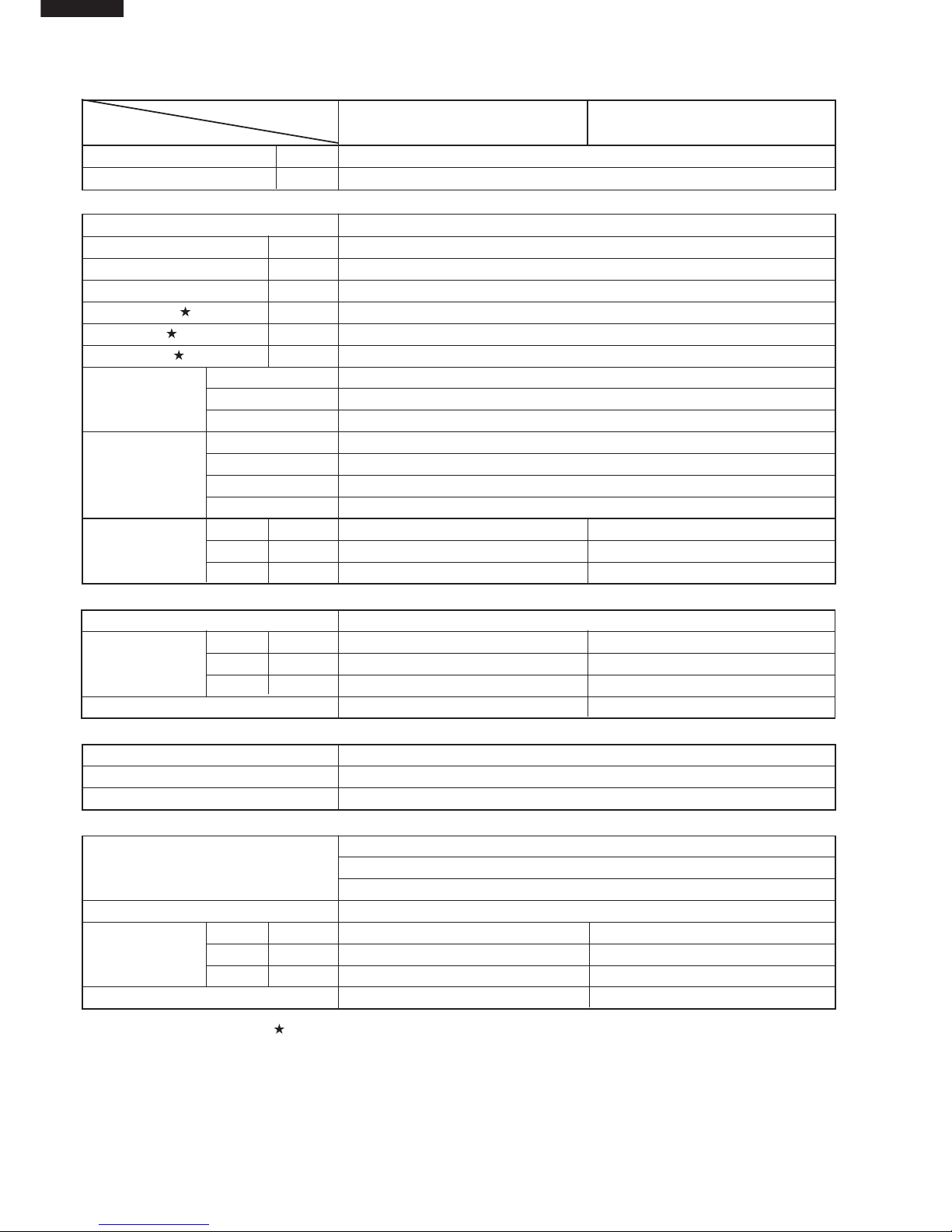
SPECIFICATIONS
MODEL
INDOOR UNI
T OUTDOOR UNIT INDOOR UNIT OUTDOOR UNIT
ITEM AH-MX122 AU-MX122 AH-MX152 AU-MX152
Cooling capacity(Min. ~ Max.) BTU/h 9000(3600~12000)
11700(5400~15000)
Moisture removalLiters/h 0.7 0.7
Electrical data
Phase Single
Rated frequencyHz 50
Rated voltage range V 198 to 242
Rated voltage V 220
Rated current A 4.2 5.5
Rated input W 818 1090
Power factor % 89 90
Type AC Single Rotary
CompressorModel 44A072QV2DJ HV187XV-S12F3
Oil charge SUNISO 4GDID 280cm3 SUNISO 4GDID 370cm
3
Evaporator Louver Fin and Grooved tube type , Pre-coat treament
Refrigerant system
Condenser Louver Fin and Grooved tube type
Control Capillary tube
Refrigerant volume
50g 740g 50g 800g
Noise level
HighdB(A) 36 43 40 48
(at cooling)
Med.dB(A) 32 43 35 48
LowdB(A) 27 43 29 48
Fan system
Drive Direct drive
Air flow quantityHighm3/min. 9.8 30 10.5 30
(at cooling)Med.m3/min. 8.8 30 9.5 30
Lowm3/min. 6.4 30 6.6 30
Fan Cross flow fan Propeller fan Cross flow fan Propeller fan
Connections
Refrigerant coupling Flare type
Refrigerant tube size Gas, Liquid 3/8", 1/4" 3/8", 1/4" 1/2", 1/4" 1/2", 1/4"
Drain piping mm O.D ø 18 - O.D
∅
18 -
Others
Compressor: Thermal protector
Safety device Fan motors: Thermal fuse
Fuse, Micro computer control
Air filters Polypropylene net (Washable)
Widthmm 815 780 815 780
Net dimensionsHeightmm 278 550 278 550
Depthmm 198 269 198 269
Net weightkg 9 33 10 38
Note: The condition of star " " marked item are ‘ISO5151’ : 1994(E), condition T1.
Page 3
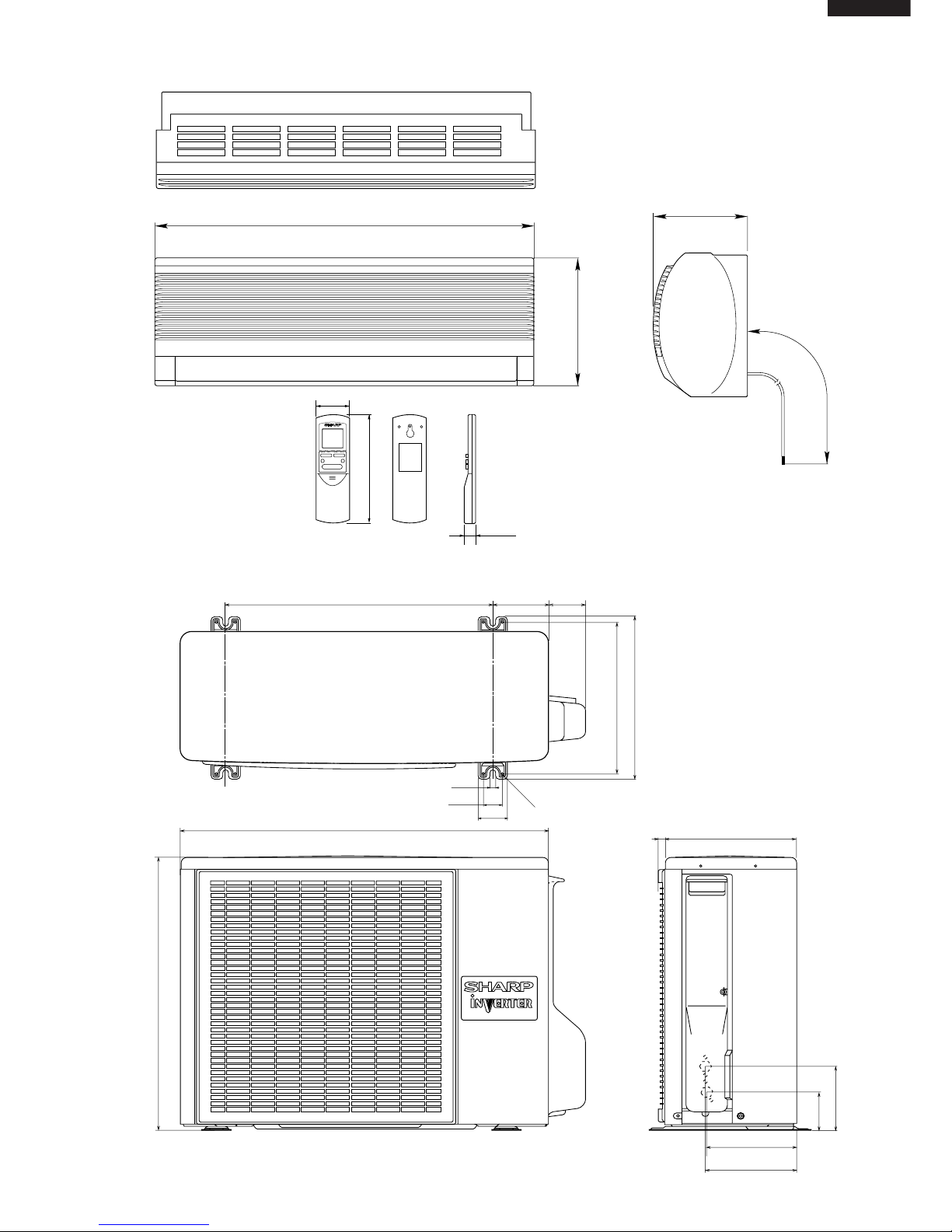
EXTERNAL DIMENSIONS
INDOOR UNIT
OUTDOOR UNIT
Length unit (mm)
19.5
58
CRMC-A442JBE0
R03(AAA) 2PCS.
SHARP CORPORATION
INVERTER AIR CONDITIONER
182
815
278
198
1100
269
179.5
182.5
136
81
780
70
540
310
335
540
12
37.5
4.5
58
158
16
Page 4
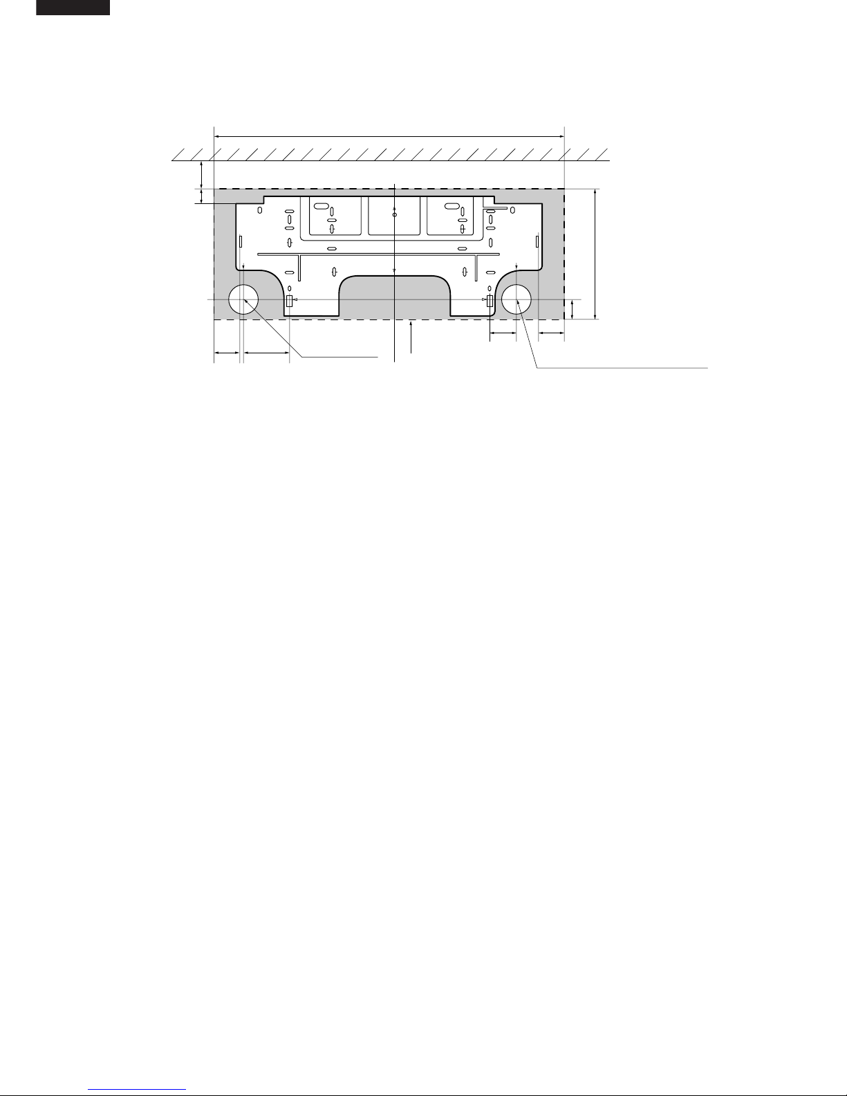
INSTALLATION DIMENSIONS
815 (unit size)
More than 50mm
E
Center of wall hole:
Leftward piping
Center of wall hole: Backward piping
Outline of indoor unit
55 95
80 55
AJ
IF
E
D
D
FA
C
J
H
I
GB
21
278 (unit size)
38
Ceiling
E
Page 5
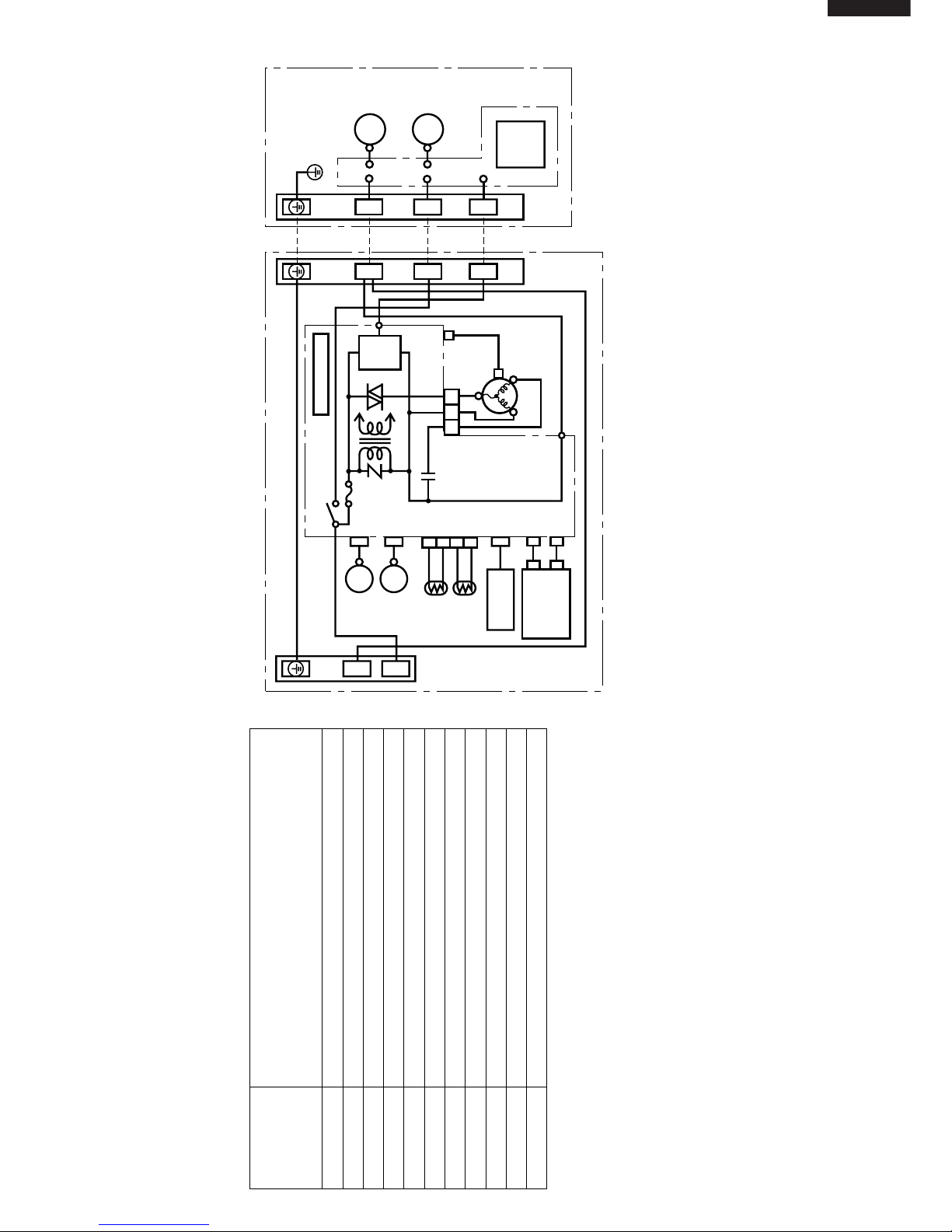
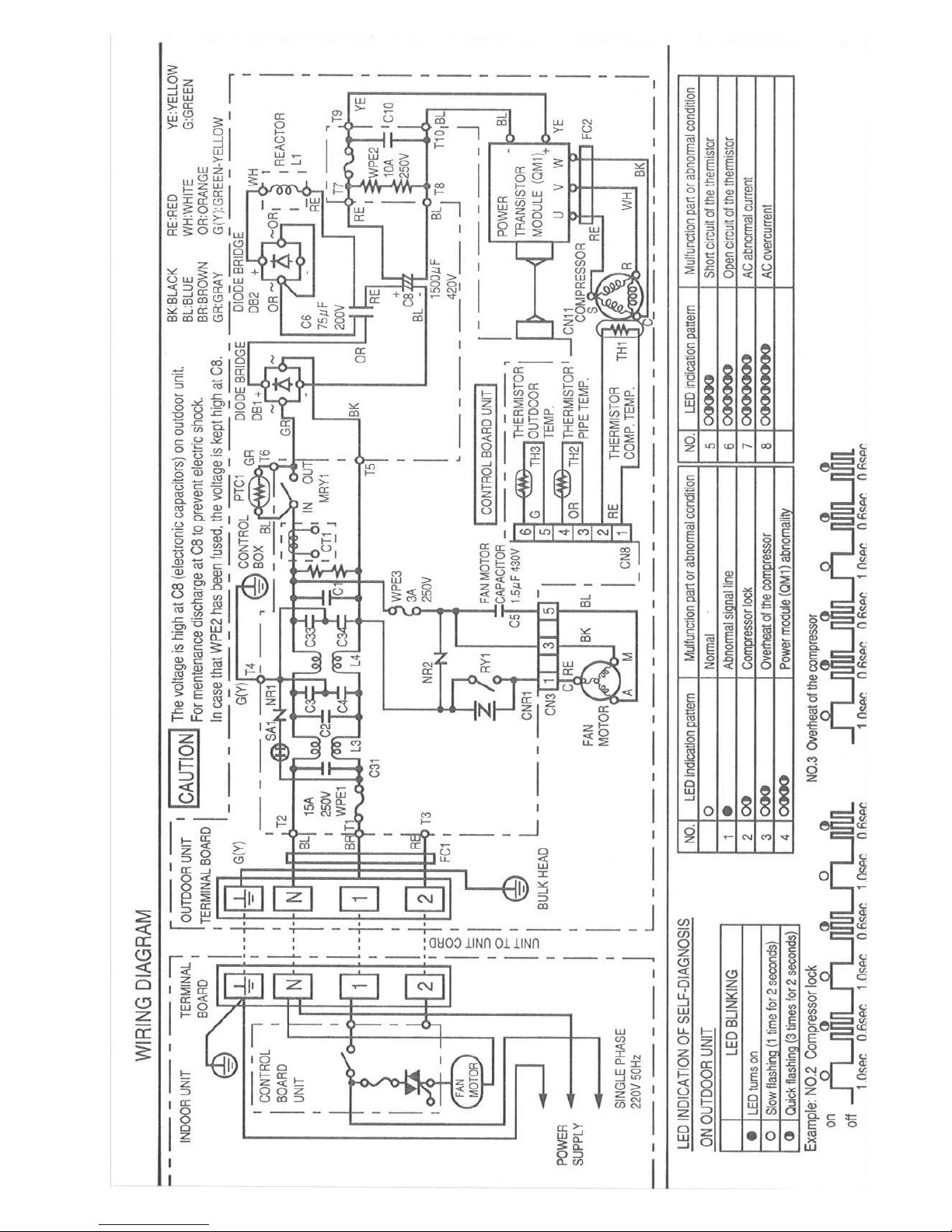
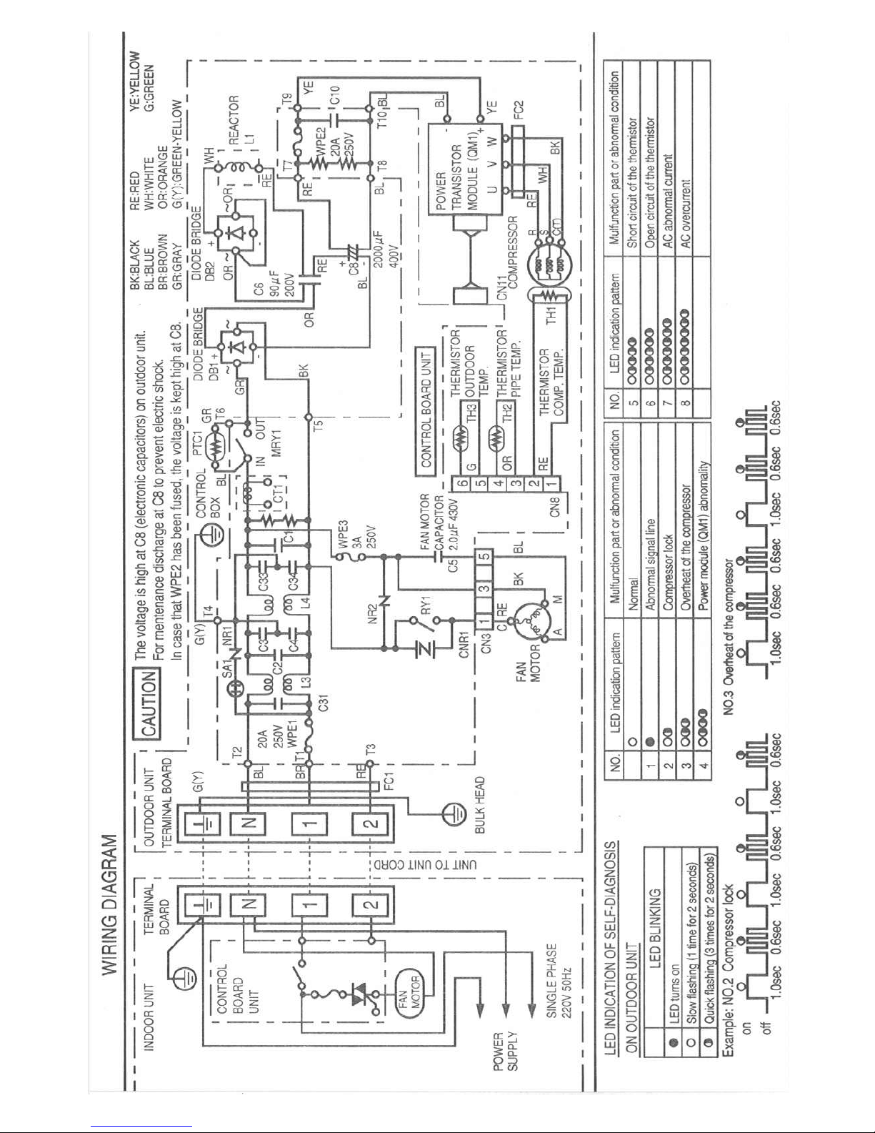
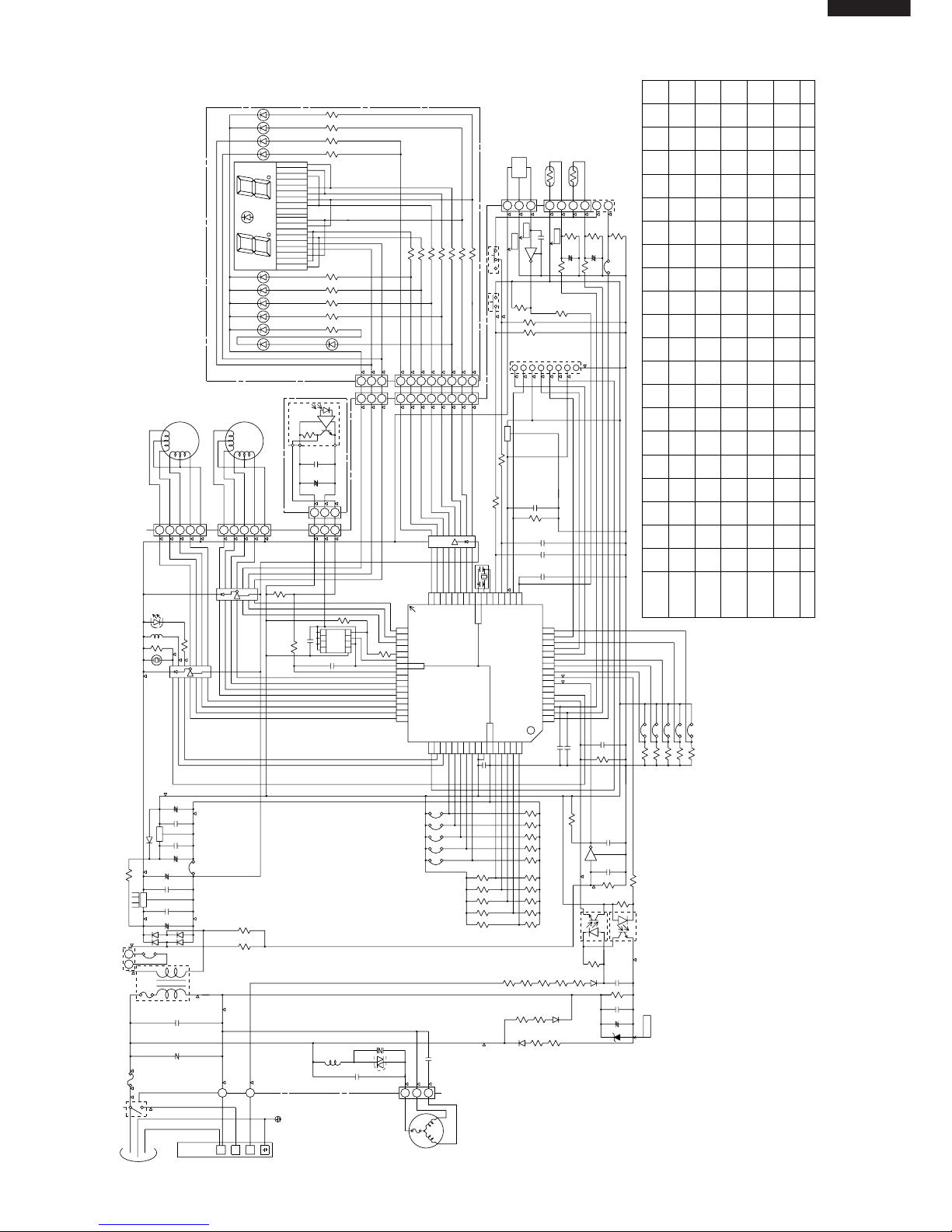
Wiring Diagram for AH-MX122 / AH-MX152
WIRING DIAGRAMS
TERMINAL BOARD 1
GREEN-YELLOW
POWER
SUPPLY
SINGLE
PHASE
INDOOR UNIT
OUTDOOR UNIT
BROWN In Out
C1
RY1
WPE1
250V
3A
CONTROL BOARD UNIT
LOUVER
(UPPER)
LOUVER
(LOWER)
ROOM TEMP.
THERMISTOR
PIPE TEMP.
THERMISTOR
TH1
TH2
341
2
CN3
YELLOW
ORANGE
RECEIVER
BOARD UNIT
DISPLAY
BOARD
UNIT
BCN2
BCN3
CN101
CN102
CN2
CN7
BCN1
TRANS1
SSR1
S
SERIAL
SIGNAL
CIRCUIT
FAN MOTOR
CAPACITOR
430V 2µF
CN6
CN1
TERMINAL BOARD 2
TERMINAL BOARD
BLACK
RED
BLUE
BLUE
5
3
1
N
BLACK
FAN MOTOR
BLUE
RED
COMPRESSOR
FAN MOTOR
UNITTOUNIT
CORD
CONTROL
BOARD
UNIT
N
1
11
NN
22
R.P.M.
SIGNAL
INTERNAL
THERMAL
FUSE
LED INDICATION FOR SELF-DIAGNOSIS
Abnormal contents
Temperature
Indicator
Blinking No.
1
2
3
4
5
6
7
141718
19
Short circuit of the outdoor thermistor
Overheat of the compressor
Abnormal AC current
Compressor lock
Open circuit of the outdoor thermistor
AC overcurrent
Power module
(
IPM
)
abnormality
Open circuit of serial signal line
Short circuit of serial signal line
Abnormal fan motor of indoor unit
Abnormal power factor module
(
AFM
)
< Indication of the abnormal condition >
LED indicator will blink, if the set
is in abnormal condition.
M
M
M
M
Page 6
Electronic Control Circuit Diagram for AU-MX122
Page 7
Electronic Control Circuit Diagram for AU-MX152
Page 8
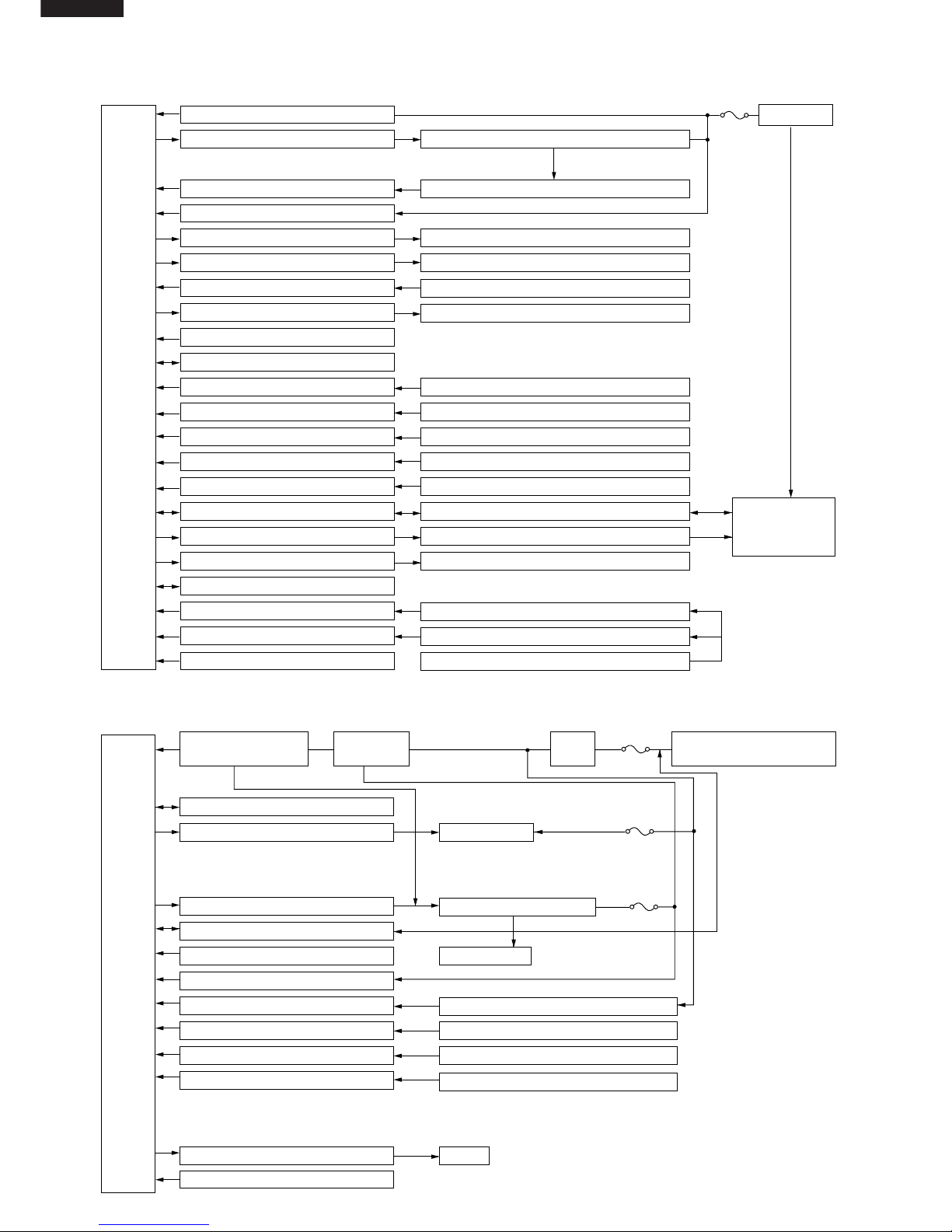
BLOCK DIAGRAMS
INDOOR UNIT
AC power
CPU
3 A
WPE1
DC power supply circuit
Fan motor phase control circuit
Rotation pulse input circuit
AC clock circuit
Louvre motor drive circuit(upper)
Louvre motor drive circuit(lower)
Remote controller signal reception circuit
Buzzer drive circuit
CPU reset circuit
CPU oscillator circuit
Room temp. detect circuit
Heat exchanger pipe thermo circuit
Compensation circuit/ select circuit
Compensation circuit
Switchover circuit
Serial I/O circuit
Compressor relay drive circuit
LED drive circuit
Auto restart circuit
Test run circuit
Auxiliary mode
Power on circuit
Room fan motor
Fan motor pulse detect
Flow direction control (louver motor upper)
Flow direction control (louver motor lower)
Wireless remote control operation
Audible operation confirmation
Room temp. thermistor
Heat exchanger pipe thermistor
Blower temperature, fan speed, model select
Outdoor ratings
Wireless, preheat
Indoor/outdoor control signal I/O
Outdoor unit power supply on/off control
LED display
Test run (forced operation)
Auxiliary mode button ON/OFF
Self diagnostics, fault diagnosis
Unit-unit wiring
(AC power and
serial signals)
CPU
15 A
protection
Outdoor fan
4-way valve
Power transistor module
Compressor
Current transformer
Compressor thermistor
Heat exchanger pipe thermistor
Outdoor temperature thermistor
Heat exchanger pipe thermistor(option)
Outdoor temperature thermistor(option)
LED
3 A
protection
10 A
protection
Power supply circuit
(built into IPM)
CPU oscillator circuit
Outdoor fan relay drive circuit
4-way valve relay drive circuit
Power transistor module drive circuit
Serial I/O circuit
CPU reset circuit
DC overcurrent detection circuit
AC overcurrent detection circuit
Compressor thermo circuit
Heat exchanger pipe thermo circuit
Outdoor temp. thermo. circuit
Winter kit circuit (option)
LED drive circuit
Test mode circuit
Filter
circuit
Smoothing
circuit
Unit-unit wiring (AC power
and serial signals)
OUTDOOR UNIT
Page 9
MICROCOMPUTER CONTROL SYSTEM
Electronic Control Circuit Diagram for AH-MX122 and AH-MX152
(CN9)
LED101
LED104
LED103
LED102
LED110
LED109
LED108
LED107
LED106
LED105
R101
R102
R103
R104
R105
R106
R107
R108
R109
1/2W
1/2W
1/2W
1/2W
220
220
300
220
220
220
220
220
100
1/2W
1/2W
1/2W
1/2W
1/2W
LED111
1/2W
1/2W
1/2W
330
R114
R40
3.3K
50V
50V
C21
C22 1000p
1000p
BCN3
BCN2
R58~R62
(SW2)
MOTOR
FAN
IC
HOLE
321
P00
P01
P02
P03
P04
P05
P06
P07
P10
P11
P12
P13
P14
P16
P17 33
34
35
36
37
38
39
40
41
42
43
44
45
46
47
48
52535455565758596061626364 P63
P64
P65
P66
P67
AVss
Vref
Vcc
P30
P31
P32
P33
P34
515049
P35
P36
P20
P21
P22
323130
P23
P24
P25
P26
P27
Vss
Xout
Xin
P40
P41
RESET
CNVss(Vpp)
P42
29282726252423222120191817
P62
P61
P60
P57
P56
P55
P54
P53
P52
P51
P50
P45
P43
1
2
3
4
5
6
7
8
9
10
11
12
13
14
15
16
NC
M3803**
IC1
(PATTERN SIDE)
PC2
PC1
4
2
4
3
1
2
4.7K
100K
+
0.047µ
50V
250V
0.01µ
680 680
2W 2W
680 680
2W 2W
680
2W
22K
P15
1
10K
10K
0.1µ
25V
8M
65432
1
PIPE TEMP.
TH2
10kΩ(25˚C)
15kΩ(25˚C)
ROOM TEMP.
TH1
C2
0.22µ
250V
NR1
IN
T
250V
OUT
RY1
WPE
N
N
2S
1
UNIT
OUTDOOR
TO
TERMINAL
BOARD
KID65783AP
IC6
10
SW1
5V
GND
12V
-24V
33K
33K
33K
33K
33K
16V
C26
0.01µ
R41
1.8K
33K
33K
33K
1000P
3
2
3
1
2
R23
3.3K
CN6
100µ
C810V
+
FAN L
FAN M
FAN H
RATE HEAT
TEA
MODEL 5
MODEL 4
MODEL 3
MODEL 2
MADEL 1
R42
R43
R44
R45
R46
R47
R48
R49
R50
R51
R52
R53
R54
R55
R56
JP 1
JP 2
JP 3
JP 4
JP 5
R67 R66
12K 12K
2W
D9
D8
R65R64
11K
2W 2W
11K
2W
C30
100µ
35V
C29
ZD1
R63
C28
D7
R57
C27
R38
R37
R36
R35
R34
JP8
JP7
JP6
R30
380
R29
680
C19
+
+
C18
10µ
16V16V
10µ
10K
(F)
R27
10K
(F)
R26
R21
R20
R19
C13
C12
C11
IC7
IC8
OSC1
FRONT
1/2W
R9
R8
C9
C10
1000p
50V
25V
0.1µ
R5
RY1
R4
BZ1
BUSY112V25V
3
4
CLOCK5SERIAL
OE
6
7
RESET
GND
8
HOT KEEP
PREHEAT
WIRELESS
2.7K
50V
1000p
1000p
50V
P37
P44
P46
P47
4
3
2
1
7
6
5
8
1
1K
FUSE
THERMAL
SSR1
470
1.8K
16
9
10K
3
1
POWER
SUPPLY
SINGLE
PHASE
21
JP10
33KR2
TRANS1
D1~4
33K
R3
+
C450V
0.1µ
7812
IC2
35V C3
1000µ
IN
0.1µ
25V
OUT
C5
+
47µ
25V
100 1/2W
R1
JP11
+
C6
25V
47µ
0.1µ
25V C7
IN
IC3
D5
7805
25V
0.1µ
R31
IC4
8
NC
9
118
13
11
C31
250V 0.01µ
SSR1
CNR1
L1
430V
C1
2µ
FUSE
THERMAL
MOTOR
FAN
531
CN1
C32
C33
680
R6
CN101
22
33
11
88
11
2233445566
77
CN102
NC
NC
10(B2)
11(A2)
12(F2)
15(B1)
18(F1)
17(G1)
16(A1)
14(CM1)
13(CM2)
9(H2)
8(C2)
7(G2)
6(D2)
5(E2)
4(H1)
3(C1)
2(D1)
1(E1)
H2
H1
CM1,2
D2
G2
A2
E2
F2
B2
C2
D1
G1
A1
C1
B1
E1
F1
33K
33K
R33
R32
JP9
JP99
TEST
POWE ON
R39
20K
C24 16V
0.01µ
1
3
2
C2550V
1000P
330
W115
1/2W
LED121
R1163301/2W
1/2W
R111
330
R112
R110
330
330
1/2W R113330
25V
0.1µ
680
680
Q1
Q2
R68
R69
3A
33K
CN7
0.1µ
25V
33µ
10V
+
5V
GND
C201
C202
IC201
BCN201
BCN1
11
33
22
6.8K
8
IC59
1
16
10K
R7
CN3
12345
LOUVER
MOTOR
UPPER
LOWER
LOUVER
MOTOR
4
5
1
CN2
2
3
∆ :TEST POINT
(NOTE)
LED101 : OPERATION
LED102 : TIMER
LED103 : ROOM TEMP.
LED104 : OUTDOOR TEMP.
SW1 : AUX.(TEST RUN)
SW2 : POWER SELECTION
LED105 : POWER MONITOR ECO
LED106 : POWER MONITOR 1
LED107 : POWER MONITOR 2
LED108 : POWER MONITOR 3
LED109 : POWER MONITOR 4
LED110 : POWER MONITOR POWER
HL
50V
C34
JP34
C1716V
0.01µ
JP23680
NONEUSE
SW2
USE
NONE
NONENONE NONENONEUSE
15K13K13K 15K15K13K13K15K13K
NONE NONE USENONE NONE NONENONE
USEUSENONE NONENONENONE USENONENONE
13K 15K 13K 13K 15K 15K13K 13K 15K
USE NONE NONE
NONENONEUSEUSE
15K13K13K 15K15K13K13K15K13K
NONE NONE USENONE NONE NONENONE NONE
NONENONENONE NONENONENONE USEUSENONENONENONE
13K 24K 15K13K 13K 15K 15K13K 13K 130K
AH-MX122
AH-MX152
AH-X10BE
AY-X08BE
AH-MX152
AH-MX122
MODEL
JP1 JP2 JP3 JP4 JP5 JP6 JP7 JP8 JP9 R51R50R49R48R47R46R45R44R43R42JP99
68K13K13K 15K15K13K13K ----47K13K
NONEUSE USE NONE USE NONE NONE USE NONE NONE
33K13K13K 2.4K3.6K13K----- 15K15K13K
USE NONE USE NONE USENONE NONE NONE
Page 10

Printed Wiring Board for AH-MX122 / AH-MX152
QPWBFB389JBZZ
HEAT
COOL
RATE
FAN H
FAN M
FAN L
R43
R51
R47
R49
R45
1
JP1
R53
R54
R55
R56
C27
JP2
JP24
R6
JP22
JP21
C9
R8
JP20
C10
R9
R7
JP3
JP4
JP5
2345
MODEL
SELECT
1
18
16
BZ1
R4
BCN1
CN2
9
1
1
5
SW1
SW2
3
4IC8
IC4
58
DPWBF
JB
R69
R68
C11
C12
R5
JP17
BCN2
31
R20
R30
C21
C22
C23
R31
R20
R19
LOUVER LOW
JP16
JP15
H
L
LOUVER UP
CN3
THERMISTOR
CN7
1
51 4
1
19
10
18
18
IC5
BCN3
JP18
JP19
IC6
OSC1
8
916
IC1
1
16
33
32
17
48
49
49
JP24
JP6
JP7
JP8
JP31
JP33
R35
R36
R34
JP27
R42
R44
R46
R48
R50
C26
R41
R40
C25
JP32
C7
R39
R37
C24
JP29
R31
PC2
PC1
JP23
C17
C29
C3
R58
C32
C2
NR1
R65
R64
C34
Q2
321
R28
C20
R27
C19
R26
C18
JP34
2
8
9
15
C31
RY1
IC3
WPE1 3A 250V
BLACK
C4
C30
ZD1
JP99
R32
JP9
C8
JP28
D5
IC3
C6
R1
JP11
TRANS1
Q1
R3
R2
C3
(CN8)
1
12 3
3
8
IC7
C33
JP10
CN9
JP30
C13
R21
JP25
R38
2
3
3
D7
R63
C28
R57
3
4
1
2
JP14
TERMINAL
BOARD
TERMINAL
BOARD
JP13
BROWN
IN
OUT
S
RED
N
BLUE
L1
SSR1
1
CN1
FAN M
5
JP12
CNR1
FAN M
CN6
R23
R66
R67
R62
R61
R60
R59
D9
D8
1
D2
D4
D1
D3
C1
3
L
GND
+12V
-24V
+5V
BCN201
C202
C201
1
3
IC201
FP389-DISPLAY
JP101
CN102
81
LED111
LED110
LED109
LED108
LED107
LED106
LED105
R109
R108
R107
R106
R105
R111
R113
R112
R110
R116
R115
JP102
JP103
R102
LED104
R103
LED103
R101
CN101
13
R114
1018
9
1
LED121
R101
LED102
LED101
TO TERMINAL " 2 " OF
TERMINAL BOARD 4P
(RED)
TO TERMINAL " N " OF
TERMINAL BOARD 4P
(BLUE)
FROM
TERMINAL " 1 " OF
TERMINAL BOARD 3P
(BROWN)
FROM
TERMINAL " 1 " OF
TERMINAL BOARD 4P
(BLACK)
FROM
FAN
MOTOR
FROM
FAN
MOTOR
FROM
THERMISTOR
FROM
LOUVER MOTOR UPPER
(TOP)
FROM
LOUVER MOTOR LOWER
(BOTTOM)
Page 11

DB1
DB2
WHITE
DB~
DB~
DB~ DB~
BLUE
BLUE
ORANGE
ORANGE
ORANGE
L1
ORANGE
C6
RED
200V 75µF
420V 1500µF
C8
TB (TERMINAL BOAOD)
N12
1
2
3
4
BLUE
BROWN
RED
FC1
FC2
GREEN/YELLOW
T2
T1
T4
T3
L3 L4
C31
275V 1µF
C4
250V 2200pF
1
2
3
4
C2
275V 1µF
C3
250V 2200pF
C34
250V 2200pF
WPE1
250V
15A
C1
275V 1µF
C33
250V 2200pF
R2 R1
1/4W
510K
1/4W
510K
CT1
T5
T6
MRY1
PTC
BLUE
GRAY
GRAY
BLACK
RED
C30
25V 100µF
C11
25V 0.1µF
C18
50V 0.1µF
R35
510
R36
510
BLUE
NOTE
1. MARK IS TEST POINT.
2. IF NOT SPECIFIED 1/4W (RESISTOR)
YELLOW
T9
T10
T7
C10
630V 0.33µF
R39
1/2W
270K
250V
10A
WPE2
13V
5V
R40
1/2W
270K
T8
C32
250V 2200pF
1 : Red 2-10 : White
10
987654321
10
987654321
CN11 (CONTROL PWB)
U
V
W
QM1 (IPM)
TM-31
FC3
RED
WHITE
BLACK
U
V
W
7805
1
2
3
R33
R32
R31
R30
R29
R28
390 U
390 X
390 V
390 Y
390 W
390 Z
65432
1
BCN11
CN8
TH3
(THERMISTOR for OUTDOOR TEMP.)
TH2
(THERMISTOR for HEAT-EXCHANGER)
TH1
(THERMISTOR for COMPRESSOR)
R38
6.8K F
C26
16V 10 F
5V
C22
16V 10 F
C21
16V 10 F
R21
6.8K F
R20
6.8K F
C15
10V 220µF
R10
6.8K F
R8
2.7K F
R9
1.00K F
D2
1
2
3
1
2
3
5V
C23
50V 1µF
PST
993D
IC3
OSC1
10MHz
5V
5V
C17
10V 100µF
2
1
F
R46
10K
JP1
R34
10K
NC
NC
5V
33343536373839404142434445464748495051525354555657585960616263
64
32313029282726252423222120191817161514131211100908070605040302
01
P27
P26
P25
P24
P23
P22
P21
P20
P17
P16
P15
P14
P13
P12
P11
P10
P07
P06
P05
P04
P03
P02
P01
P00
V
SS
P37
P36
P35
P34
P33
P32
V
CC
VSSXIX0MOD1
MOD2
RST
P60
P61
P62
P63
P64
AVSSAVR
AVCCAN7
AN6
AN5
AN4
AN3
AN2
AN1
AN0
P40
P41
P42
P43
P44
P45
P46
P47
P30
P31
NCNCNC
NC
NCNCNCNCNCNCNCNCNCNCNCNCNC
IC1 MB89855
C16
25V 0.1µF
C20
10V 100µF
5V
R41 10K
R3
2.2K
5V
LED1
C5
430V 1.5µF
WPE3
250V
3A
NR2
Fan
Motor
5
3
1
CN3
T11
RY1
CNR1
(WINTER KIT)
C12
250V 4700pF
C14
50V 1000pF
C13
25V 0.01µF
R4
D1
3.3K
R6
2.7K
R5
5.6K
R7
4.7K
PC817X7
PC1
PC2
PC853H
1
23
4
1
23
4
5V
R11
2W 1.0K
R12
2W 1.0K
R13
2W 1.0K
R17
10K
R16
10K
13V
RY1
D6
Q1
MRY1
D8
Q3
5V
NR1
SA1
Electronic Control Circuit Diagram for AU-MX122
Page 12

DB1
DB2
WHITE
DB~
DB~
DB~ DB~
BLUE
BLUE
ORANGE
ORANGE
ORANGE
L1
ORANGE
C6
RED
200V 90µF
400V 2000µF
C8
TB (TERMINAL BOAOD)
N12
1
2
3
4
BLUE
BROWN
RED
FC1
FC2
GREEN/YELLOW
T2
T1
T4
T3
L3 L4
C31
275V 1µF
C4
250V 2200pF
1
2
3
4
C2
275V 1µF
C3
250V 2200pF
C34
250V 2200pF
WPE1
250V
20A
C1
275V 1µF
C33
250V 2200pF
R2 R1
1/4W
510K
1/4W
510K
CT1
T5
T6
MRY1
PTC
BLUE
GRAY
GRAY
BLACK
RED
C30
25V 100µF
C11
25V 0.1µF
C18
50V 0.1µF
R35
510
R36
510
BLUE
NOTE
1. MARK IS TEST POINT.
2. IF NOT SPECIFIED 1/4W (RESISTOR)
YELLOW
T9
T10
T7
C10
630V 0.33µF
R39
1/2W
270K
250V
20A
WPE2
13V
5V
R40
1/2W
270K
T8
C32
250V 2200pF
1 : Red 2-10 : White
10
987654321
10
987654321
CN11 (CONTROL PWB)
U
V
W
QM1 (IPM)
TM-35
FC3
RED
WHITE
BLACK
U
V
W
7805
1
2
3
R33
R32
R31
R30
R29
R28
430 U
430 X
430 V
430 Y
430 W
430 Z
65432
1
BCN11
CN8
TH3
(THERMISTOR for OUTDOOR TEMP.)
TH2
(THERMISTOR for HEAT-EXCHANGER)
TH1
(THERMISTOR for COMPRESSOR)
R38
6.8K F
C26
16V 10 F
5V
C22
16V 10 F
C21
16V 10 F
R21
6.8K F
R20
6.8K F
C15
10V 220µF
R10
6.49 F
R8
1.8K F
R9
1.00K F
D2
1
2
3
1
2
3
5V
C23
50V 1µF
PST
993D
IC3
OSC1
10MHz
5V
5V
C17
10V 100µF
2
1
F
R46
10K
JP1
R34
10K
NC
NC
5V
33343536373839404142434445464748495051525354555657585960616263
64
32313029282726252423222120191817161514131211100908070605040302
01
P27
P26
P25
P24
P23
P22
P21
P20
P17
P16
P15
P14
P13
P12
P11
P10
P07
P06
P05
P04
P03
P02
P01
P00
V
SS
P37
P36
P35
P34
P33
P32
V
CC
VSSXIX0MOD1
MOD2
RST
P60
P61
P62
P63
P64
AVSSAVR
AVCCAN7
AN6
AN5
AN4
AN3
AN2
AN1
AN0
P40
P41
P42
P43
P44
P45
P46
P47
P30
P31
NCNCNC
NC
NCNCNCNCNCNCNCNCNCNCNCNCNC
IC1 MB89855
C16
25V 0.1µF
C20
10V 100µF
5V
R41 10K
R3
2.2K
5V
LED1
C5
430V 2.0µF
WPE3
250V
3A
NR2
Fan
Motor
5
3
1
CN3
T11
RY1
CNR1
(WINTER KIT)
C12
250V 4700pF
C14
50V 1000pF
C13
25V 0.01µF
R4
D1
3.3K
R6
2.7K
R5
5.6K
R7
4.7K
PC817X7
PC1
PC2
PC853H
1
23
4
1
23
4
5V
R11
2W 1.0K
R12
2W 1.0K
R13
2W 1.0K
R17
10K
R16
10K
13V
RY1
D6
Q1
MRY1
D8
Q3
5V
NR1
SA1
Electronic Control Circuit Diagram for AU-MX152
Page 13

Printed Wiring Board for AU-MX122
Printed Wiring Board for AU-MX152
T5(DB1~)
(BLACK)
C5
NR2
WPE3
R2
R1
CT1
3A 250V
RY1
CNR1
CNR2
RY2
WINTER KIT
(OPTION)
T11
(GRAY)
T10
T9
WPE2
10A
250V
(BLUE)
(YELLOW)
IPM
13V
R33
R32
R31
R30
R29
R28
BCN11 (IPM)
JP2
C32
C10
R40
R39
JP20
JP1
R46
R34
JP14
JP15
JP16
JP12
LED1
JP10
Q3
C33
Q2
Q1
C1
SA1
D7
D6
JP9
JP8
JP7
JP4
JP6
JP5
JP3
IC2
C11
C16
JP21
JP17
JP18
R41
(4-WAY VALVE)
CN4
(FAN MOTOR)
CN3
1
3
1
5
10
12
E&J
V&W2
IPM
(RED)
(BLUE)
T7
CB
T8
CB
WINTER KIT (OPTION)
CN10
JP22
JP19
C17
R35
JP25
C18
C23
R20
C21
R13
R12
R11
C22
C26
R21
R38
R36
F
JP23
JP24
CN912
14
TERMINAL
FUSE
ONLY
W2
IC3
OSC1
R4
C12
C31
D1
R16
C13
R17
JP16
C14
R1
R6
R5
PC2
PC1
C3
3
4
1
2
2
1
4
3
L3
C4
L4
C34
C2
NR1
WPE1
15A 250V
OUT
32
33
IC1
1
CN8
(THERMISTOR)
16
64
R3
C15
R10
D8
JP11
C30
R8
D2
R9
E
C
B
E
C
B
E
C
B
C20
BCE
Q4
Cool/40Hz
QPWBFB397JBZZ
DPWBFA JBKZ
0
MRY1
PTC
(BLUE)
IN
(GRAY)
(DB1~)
(RED)
(BLUE)
(BROWN)
(GREEN/
YELLOW)
T3
T2
2
N
1
T1
T4
DIP
T6(GRAY)
PTC
5V
GND
FROM
FAN MOTOR
FROM
4 WAY VALVE
(EXCEPT FOR
AU-X08BE AND
AUX10BE)
TO
POWER TRANSISTOR
MODULE QM1
OPTION
(FROM WINTER KIT)
FROM
POWER TRANSISTOR
MODULE QM1 " "
FROM
POWER TRANSISTOR
MODULE QM1 " "
FROM
ELECTLYTIC
CAPACITOR
C8 " "
FROM
ELECTLYTIC
CAPACITOR
C8 " "
FROM
THERMISTOR
OPTION
(WINTER KIT)
FROM
TERMINAL
BOARD " N "
FROM
TERMINAL
BOARD " 2 "
FROM
TERMINAL
BOARD " 1 "
FROM
CONTROL BOX
FROM
DIODE BRIDGE
DB1 " ~ "
FROM
DIODE BRIDGE
DB1 " ~ "
FROM
PTC1
T5(DB1~)
(BLACK)
C5
NR2
WPE3
R2
R1
CT1
3A 250V
RY1
CNR2
CNR1
RY2
WINTER KIT
(OPTION)
T11
(GRAY)
T10
T9
WPE2
20A
250V
(BLUE)
(YELLOW)
IPM
R33
R32
R31
R30
R29
R28
C10
C40
R52
OUT
C45
CN14
1
41
CN12
4
IN
IC2
C45
JP23
R50
R40
R39
JP1
R46
C33
Q2
Q1
C1
SA1
D7
D6
JP2
JP17
JP19
JP18
(4-WAY VALVE)
CN4
(FAN MOTOR)
CN3
1
3
1
5
IPM
(RED)
(BLUE)
T7
CB
T8
CB
WINTER KIT (OPTION)
CN10
JP16
JP20
C17
R35
R36
JP25
C18
C23
R20
C21
R13
R12
R11
C22
C26
R21
R38
F
JP21
R10
JP22
14
IC3
C15
OSC1
R4
C12
C31
D1
R16
C13
R17
JP12
R7
C14
JP13
R6
R5
R5
PC2
PC1
C3
3
4
1
2
2
1
4
3
L3
C4
L4
C34
C2
NR1
WPE1
25A 250V
OUT
32
33
32
IC1
1
CN8
(THERMISTOR)
16
64
C20
LED1
R59
D8
C30
E
C
B
E
C
B
B
C
E
B
C
E
Q4
R3
R41
C12
JP7
JP6
R9
D2
R8
JP3
R57
C44
R58
JP5
JP4
R60
121
BCN11 (IPM)
JP8
JP9
JP10
JP11
C16
Q3
Cool/40Hz
QPWBFB426JBZZ
DPWBFA
JBKZ
0
MRY1
PTC
(BLUE)
IN
(GRAY)
(DB1~)
(RED)
(BLUE)
(BROWN)
(GREEN/
YELLOW)
T3
T2
2
N
1
T1
T4
DIP
T6(GRAY)
PTC
2
1
4
3
3
4
1
2
PC4
PC3
R34
C32
JP14
JP15
GND
R53
C41
14
8
IC4
5
R54
C43
61
CN13
18V
13V
R51
5V
FROM
FAN MOTOR
FROM
4 WAY VALVE
(EXCEPT FOR
AU-X13BE)
OPTION
(FROM WINTER KIT)
FROM
POWER TRANSISTOR
MODULE QM1 " "
FROM
POWER TRANSISTOR
MODULE QM1 " "
FROM
ELECTLYTIC
CAPACITOR
C8 " "
FROM
ELECTLYTIC
CAPACITOR
C8 " "
FROM
THERMISTOR
OPTION
(WINTER KIT)
FROM
TERMINAL
BOARD " N "
FROM
TERMINAL
BOARD " 2 "
FROM
TERMINAL
BOARD " 1 "
FROM
CONTROL BOX
FROM
DIODE BRIDGE
DB1 " ~ "
FROM
DIODE BRIDGE
DB1 " ~ "
FROM
PTC1
TO
TRANSISTOR
MODULE QM1
Page 14

1. INDOOR UNIT
1-1 Temperature Adjustment
a. Normal control
Proportional control (P control)
When the temperature zone changes, this control
changes the frequency by one rank to move closer
to the set value.
Integral control (I control)
When the temperature zone has set time in the
same zone, this control changes the frequency
by one rank to move closer to the set value.
(Excluding the h zone.)
b. Initial control
The initial frequency is determined as shown in
the tables below based on the difference between
the temperature adjustment setting at the
beginning of operation and the room temperature.
After operation begins, normal control is performed
and therefore the correspondences in the tables
below will not hold.
FUNCTIONS
c. Temperature adjustment
The temperature adjustment range is changed by
changing the operating mode with the operation switch.
(1) Cooling
If the room temperature is in the c zone when
operation begins,proportional/integral control is not
performed, and the machine runs at frequency
code 9 power until the i zone is reached. When the
i zone is reached, the frequency changes to the
frequency code determined by fuzzy calculation,
and after thatproportional/integral control is
performed.
(2) Dry
After operation begins, 2 minutes (running at the h
zone) of the room temperature is stored in memory,
and that becomes the set value.
(3) Circulation
The frequency code 0 is sent to the outdoor
machine, and only the fan of the indoor machine
runs, the compressor does not run.
1-2 Indoor fan control
(1) Control for indoor freezing prevention
If the temperature of the indoor heat exchanger
stays below approximately 0°C for four minutes
during cooling or dry, this control stops the
compressor. Over 2˚C the compressor will run
again.
(2) Indoor fan and operating frequency
The indoor fan has 12 speeds, and changing is
done in four stages, "Auto", "High", "Med", and
"Low". The relations between the indoor fan speed,
air quantity setting, operating frequency, and indoor
heat exchanger are shown in the following charts.
Cooling
Room
temp.
zone
Frequency
Code
c9
d8
e7
f5
g3
h2
i1
j OFF
e7
f5
g3
h2
i1
Dry
Room
temp.
zone
Frequency
Code
e4
d5
f3
g2
h2
h1
1
2
i1
j
0
Full power
operation onl
y
Although the initial value
of the h zone is 1, it changes
to 2 after a lapse of 15 minutes.
e
d
g
f
h
j
i
+2.00
+2.66
+1.33
-1.00
+0.66
-1.33
Dry
MEMORY SET VALUE
OFF
1
2
3
4
5
6
7
8
9
10
11
123456789OFF
Fan speed
Frequency cord
Fan speed : High / Med / Low
High
Med
Low
OFF
1
2
3
4
5
6
7
8
9
10
11
123456789OFF
Fan speed
Frequency cord
Fan speed : Automatic
COOLING
c
d
e
f
g
h
i
j
+3.33
+2.66
SET VALUE
-0.66
+0.66
+2.00
Cooling
+1.33
Page 15

ON
OFF
ON
ON
Air conditioner
operation
Compressor
relay
100 sec.
ON
OFF
OFF
Air conditioner
operation
Compressor
relay
100 sec.
ON
ON
ON
OFF
ON
OFF
Air conditioner
operation
Compressor
relay
100 sec.
80 sec.
ON
1-3 Automatic operation
The operating mode and temperature setting are
determined by the room temperature and the external
air temperature.
12
11
10
9
8
7
6
5
4
3
2
1
01234
5
f
e
d
(Full power only)
j
i
h1 h2, g
Dry
Operating frequency code
Fan speed
1-6 Swing louvres
Louvres are moved by stepping motors to perform
swing and fixing in the set position. If the "FLOW
DIRECTION" button is pressed during swing, they
will stop. If the "FLOW DIRECTION" button is pressed
while they are stopped, they will swing.
1-7 Restart control
Once the compressor stops, this control prevents it
from starting again for 3 minutes. It also prevents
starting for 80 seconds immediately following plugging
into the power outlet.
1-8 One-hour operation
If this button is pressed when operation is stopped,
operation will begin and then stop after 1 hour. If
pressed when it is operating, will stop after one hour.
When the set temperature is adjusted within the
range of ±2˚C by the remote control's key. ( ),
the changeover judgement room temp. will also be
shifted within the range of ±2˚C.
1-4 ON-timer
The ON-timer is set by pressing the ON-timer button.
In order to attain the set temperature at the set time,
the operation starting time is corrected by fuzzy
computing one hour before the set time.
1-5 OFF-timer
The OFF-timer is set by pressing the OFF-timer
button. Operation is as follows:
1-9 Full power operation
Immediately begins cooling or heating at maximum
power and air flow.
(During cooling) Operates at setting of 18°C.
1-10 Power ON start
If a jumper wire is inserted into the place indicated
JP99 on the indoor control board, and the power
plug is inserted. cooling mode will be automatically
determined by the room temperature sensor on the
main unit, and operation will begin.
1-11 Compressor relay
(1)It is ON during operation, and when operation is
stopped, goes OFF after a delay of 100 seconds
(not immediately).
(2)The minimum OFF time of the relay is 80 seconds.
It will not go ON again before 80 seconds elapses.
(3) If air conditioner operation is turned on again
during the 100 second delay before the
compressor relay goes off, the compressor relay
will stay on.
Cooling
(24˚C)
(Room temperature
- 2°C)
Cooling
(25˚C)
Cooling
(26˚C)
(Dry)
Room
temperature
(˚C)
29
28 34
Outdoor
temperature (°C)
Cooling
Set temperature
By fuzzy computing
Set the shift up time
Final ( Cooling setting + 1°C)
Dry Same as above
(Final setting + 1°C)
1°C
Stops
Timer set time
1
hour
Timer operation starts
Room
temperature
*During Cooling / Dry
Page 16

Model
Set valve
Cool
7.5A
AU-X10BV
56˚C
58˚C
55˚C
Lower 5Hz once every 60 seconds
Lower 15Hz once every 120 seconds
Overheating prevention line 1
Overheating prevention line 2
Clear line
1-12 Auto Restart
When power failure occures, after power is
recovered, the unit will automatically restart in the
same setting which were active before the power
failure.
Operating mode (Cool, Dry)
Temperature adjustment (within 2˚C range)
automatic operation
Temperature setting
Fan setting
Air flow direction
Power ON/OFF
Automatic operation mode setting
Swing louver
Setting not memorized
Timer setting
Full power setting
1-13 Indoor/outdoor temperature display
Every time the Temperature check button is
pressed on the remote control, the display changes
in the order of indoor temperature
outdoor
temperature
no display. The temperature is
displayed on the temperature indicator on the main
unit to be referred to for energy saving.
(When the unit is not running, the display changes
between indoor temperature and no display.)Indoor
temperature is the temperature of the suction air
measured by the room thermistor, and outdoor
temperature is that measured by the outdoor
temperature thermistor. When indoor temperature
is displayed, the indoor LED on the main unit is lit,
and when outdoor temperature is displayed, the
outdoor LED is lit. For 90 seconds after the
operation starts, - - is displayed instead of the
actual outdoor temperature since it is still being
measured.Because of the effect of the exchanger,
the unit cannot confirm the exact indoor
temperature right after the operation is terminated.
Therefore, for one hour since the operation is
stopped, the indoor temperature immediately before
the operation is stopped is displayed. After over
one hour since it is stopped, the unit displays the
actual room temperature at that point.
1-14 Error diagnostic display
(a) Indoor unit
(1) When an error is detected, all relays are
turned off. At the same time, the details of the
error are displayed by flashing the number
corresponding to the type of the error. The
details can also be displayed by pressing down
the emergency operation switch for 5 seconds
or more in the state ofoperation stop.However,
if the operation is continued only in the serial
open state and the state remains unchanged
after that, the main relay is turned off in 8
minutes. In the serial short state, the error is
not displayed and the operation is continued. If
the unit stays in the same state, the main relay
is turned off in 8 minutes. Although the error is
not displayed, it is memorized and can be
displayed when it is recalled.
(2) If the operation is stopped and the emergency
operation button is pressed down for 5 seconds
or more, the self-diagnosis memory can be
recalled.
2. OUTDOOR UNIT
2-1 Frequency control
(1) AC current peak control
(3) Details of self-diagnosis (error mode) are
informed by the flashing number as well as the
lighting pattern of the operation lamp which
flashes with the timer lamp.(For details, refer to
Error diagnostic method.)
(2) Control for prevention of outdoor heat exchanger
overheating. If the temperature of the outdoor heat
exchanger exceeds the overheating prevention line
1 or 2 during cooling, the operating frequency is
lowered by approximately 5 to 15 Hz.
After that, the frequency is lowered by approximately
5 once every 60 seconds or approximately 15Hz
once every 120 seconds. When the temperature of
the outdoor heat exchanger goes below the
overheating prevention clear line, the frequency is
raised by approximately 5 Hz once every 60 seconds,
and normal operation is restored. If the frequency is
lowered to minimum frequency without the
temperature of the outdoor heat exchanger
decreasing and this condition lasts for 1 minute, the
compressor will be stopped.
(3) Control for prevention of compressor chamber
overheating
If the compressor chamber temperature exceeds
approximately 105°C during compressor operation,
the operating frequency is lowered by approximately
5 Hz. After that, the frequency is lowered by
approximately 5 Hz once every 60 seconds. When
the compressor chamber temperature goes below
approximately 104°C, the frequency is raised by
approximately 5 Hz once every 60 seconds, and
normal operation is restored.
If the frequency is lowered to minimum
frequencywithout the compressor chamber
temperature decreasing and this condition lasts for 1
minute, the compressor will be stopped.
(4) Control for prevention of indoor heat exchanger
freezing
If the temperature of the indoor heat exchanger goes
below approximately 5°C during cooling(only Full
power operation), the operating frequency is lowered
by approximately 5 Hz. After that, the frequency is
lowered by approximately 5 Hz once every 60
seconds. When the temperature of the indoor heat
exchanger rises above approximately 5°C, the
frequency is raised by approximately 5 Hz once
every 60 seconds, and normal operation is restored.
If the temperature of the indoor heat exchanger goes
down to approximately 0°C and this condition
continues for 4 minutes, the compressor is stopped.
When the temperature rises above approximately
2˚C, normal operation is restored.
Page 17

2-2 Overcurrent protection
(1) Compressor lock detection
If the set value 2.7A of AC current is exceeded in 6
seconds when operation begins, operation is stopped.
In this case, the compressor outdoor fan does not
stop, and 170 seconds after operation is stopped,
another try will be made. Three retries are allowed.
On the fourth retry, a complete stop request signal is
sent to the indoor unit, and the outdoor unit will
remain stopped until reset is performed. At this time,
the 3-minute delay for control of the outdoor unit will
not function; therefore, do not cancel by removing the
plug and cutting the power.
(2) DC overcurrent detection, AC overcurrent detection
To protect against overcurrent due to sudden changes
in load, the compressor is stopped if the set value
26A DC is exceeded in the DC section, or the set
value 11A AC is exceeded in the AC section. In this
case, the outdoor fan does not stop, and 170 seconds
after operation is stopped, another try will be made.
Three retries are allowed. On the fourth retry, a
complete stop request signal is sent to the indoor
unit, and the outdoor unit will remain stopped until
reset is performed. At this time, the 3-minute delay for
control of the outdoor unit will not function; therefore,
do not cancel by removing the plug and cutting the
power.
2-3 Compressor protector control
If the temperature of the compressor chamber exceeds
114°C, the compressor is stopped. In this case, the
outdoor fan does not stop, and when the compressor
chamber temperature decreases to 100°C three
minutes after operation is stopped, another try will be
made. Three retries are allowed. On the fourth retry,
a complete stop request signal is sent to the indoor
unit, and the outdoor unit will remain stopped until
reset is performed. At this time, the 3-minute delay for
control of the outdoor unit will not function; therefore,
do not cancel by removing the plug and cutting the
power.
2-4 Power transistor module protector
If the temperature of the chips in the power transistor
module exceeds 105 °C, the compressor is stopped.
In this case, the outdoor fan does not stop, and when
the temperature of the chips in the power transistor
module decreases to 105 °C 170 seconds seconds
after operation is stopped, another try will be made.
Three retries are allowed. On the fourth retry, a
complete stop request signal is sent to the indoor
unit, and the outdoor unit will remain stopped until
reset is performed. At this time, the 3-minute delay for
control of the outdoor unit will not function; therefore,
do not cancel by removing the plug and cutting the
power.
2-5 Serial signals
(1) Serial signals consist of all 96-bit signals.
(2) If the outdoor unit does not receive a serial signal, it
will stop approximately 30 seconds later. Note that
this is true only of normal operation; in test mode, it
does not stop and operation takes place based on the
test mode commands.
Page 18

FUNCTION AND OPERATION OF PROTECTIVE PROCEDURES
Function
NO
Description Detection
time
Restart
condition
Restart
times
Indoor
Outdoor
Operation Self diagnostic
display
1
2
3
4
5
Indoor fan
lock
Indoor fan
rpm error
Indoor
freezing
guard
DC
overcurrent
AC
overcurrent
Compressor
lock
Stops operation if no revolution pulse
signal is input from the indoor fan motor for
one minute.
Stops operation if the revolution pulse
signal from the indoor fan indicates low
rpm (approximately 300 rpm or less).
Lowers the operating frequency if the
temperature of the indoor heat exchanger
goes below 5°C during cooling. Stops the
compressor if the temperature stays below
0°C for 4 minutes.
Stops the compressor if a current of
approximately 26A or more flows in the
power transistor module. Also stops the
compressor if the temperature of the
power transistor module is exceeds 105°C.
Lowers the operating frequency if the
compressor AC current exceeds
7.5A
Stops the compressor if the current
exceeds at 40Hz or less set valve.
Stops the compressor if the compressor
AC current exceeds 2.7A immediately after
activating the compressor (in 6 seconds).
When indoor
fan is revolving
During cooling
and dry
During
compressor
operation
During
compressor
operation
Immediately
after
compressor
activation.
Operation OFF
Automatically
restarts when the
exchange
temperature rises
above the freezing
prevention
temperature (above
2°C)
Automatically
restarts after safety
time (170 seconds)
Automatically
restarts after safety
time (170 seconds)
Automatically
restarts after safety
time (170 seconds)
No limit
No limit
4 times
4 times
4 times
Yes
No
Yes
Yes
Yes
No
No
Yes
Yes
Yes
Page 19

Function
NO
Description Detection
time
Restart
condition
Restart
times
Indoor
Outdoor
Operation Self diagnostic
display
6
7
8
9
10
11
12
Compressor
overheating
control
Compressor
high
temperature
error
Outdoor heat
exchanger
overheating
control
Outdoor
thermistor
short
Outdoor
thermistor
open
AC abnormal
current error
Serial signal
error
Lowers the operating frequency if the
temperature of the compressor chamber
thermistor (TH1) rises above 105°C.
Stops the compressor if the thermistor
stays above 105°C for 1 minutes at
minimum frequency or less.
Stops the compressor if the compressor
chamber thermistor is above 114°C.
(Or when TH1 shorts)
Lowers the operating frequency if the
temperature of the outdoor heat exchanger
rises above 56°C during cooling. Stops the
compressor if the temperature stays above
56°C for 1 minute at minumum frequency.
Stops the compressor if an outdoor
thermistor (excluding TH1) shorts.
Stops the compressor if the circuit of an
outdoor thermistor breaks.
Stops the compressor if if the operating
frequency is above 70 Hz and the
compressor current is below 1.0 A.
Turns the compressor relay off if the indoor
unit does not receive a serial signal from
the outdoor unit for 8 minutes.
Stops the compressor if the outdoor unit
does not receive a serial signal from the
indoor unit for 30 seconds.
During
compressor
operation
During
operation
During
compressor
operation
When
compressor is
activated
When
compressor is
activated
During
compressor
operation
During
operation
During
operation
Automatically
restarts after safety
time (170 seconds)
Automatically
restarts when
thermistor (TH1)
temperature falls
below 100°C
(approximately 30
minutes)
Automatically
restarts after safety
time (170 seconds)
Automatically
restarts after safety
time (170 seconds)
Automatically
restarts after safety
time (170 seconds)
Automatically
restarts after safety
time (170 seconds)
Automatically
restarts less than 8
minutes after
operation stops
Restarts after
reception of serial
signal
No limit
4 times
No limit
4 times
4 times
4 times
No limit
No limit
No
Yes
No
Yes
Yes
Yes
Yes
No
Yes
No
Yes
Yes
Yes
Yes
Page 20

: Blinks at 2-second intervals : OFF : ON : Blinks 3 times at 0.2-second intervals
Indoor and outdoor unit
completely stopped
Indoor unit
operating
Outdoor unit
completely stopped
Display by indoor unit operation lamp
Displayed in a pattern which comes on at the same
time as the timer lamp
4 seconds off
Temperature display
What to check, procedure
Display by
outdoor
unit lamp
LED 1
Diagnosis
Solution
Condition
of indoor
and
outdoor
unit
Normal
Once
Twice
3 times
4 times
5 times
6 times
7 times
Compressor lock error
DC overcurrent error
AC overcurrent error
Normal
Serial short
Serial open
Does compressor active ? Does it go off immediately after active ?
1. Check the circuit in the power transistor module.
2. Is the outdoor fan revolving ?
1. Is the discharge outlet of the outdoor unit clogged ?
1. Check the wiring between units.
1. Check the wiring between units.
1. Check the wiring between units.
2. Check the fuse in the outdoor unit.
3. Indoor control board.
4. Outdoor control board.
1. Measure the resistance of thermistor TH2 on the outdoor unit
(see Figure 2).
1. Replace power transistor
module
1. Clear the discharge outlet.
1. Rewire.
1. Rewire.
Indoor fan out of order
1. Is the fan motor locked ?
2. Is the wiring connector firmly fitted ?
3. Is the speed signal applied to the motor ?
Overheat of the comp-
ressor error
(protector operating) or
outdoor compressor
thermistor TH1 short
Outdoor power supply
does't turn on.
Wiring mistake.
1. Rewire.
2. Replace the fuse, replace the
outdoor board assembly.
3. Replace the board.
4. Replace the board.
1. Replace fan motor
2. Reattach.
3. Replace the indoor control board
assembly.
1. Replace the outdoor control board
assembly
(Current transformer wire break.)
1. Reattach.
2. Replace the outdoor thermistor
assembly.
1. Replace the outdoor thermistor
assembly.
1. Clear the discharge outlet.
2. Assure power supply voltage.
3. Refill to rated amount.
4. Replace the outdoor ther-mistor
assembly.
5. Replace the indoor control board
assembly or only TH2.
1. Apply an external shock to the
compressor.
2. Replace the compressor.
1. Can voltage be detected at the current transformer on the outdoor
unit control board?
1. Are the connectors of the outdoor unit thermistors well attached ?
2. Measure the resistance of thermistors TH1 and TH2 on the
outdoor unit (see Figure 2).
1. Is the discharge outlet of the outdoor unit clogged ?
2. Is the power supply voltage at least 198 V at full power operation ?
3. Check for refrigerant leaks at the tubing connections.
4. Measure the resistance of compressor thermistor TH1 on the
outdoor unit (see Figure 2).
5. Measure the resistance of heat exchanger pipe thermistor TH2 on
the indoor unit (see Figure 1).
AC abnormal current
error
Open circuit of the
thermistor error
Short circuit of the
thermistor error
1
sec..
1
sec
0.6
sec.
1
sec.
1
sec.
1
sec.
1
sec.
1
sec.
0.6
sec.
1
sec.
1
sec.
1
sec.
1
sec.
1
sec.
1
sec.
Short circuit of the outdoor thermistor
1
sec.
1
sec.
1
sec.
Overheat of the compressor
0.6
sec.
0.6
sec.
1
sec.
0.6
sec.
1
sec.
0.6
sec.
1 time
2 times
ON
OFFONOFF
BREAK DOWN DIAGNOSIS PROCEDURE
Self-diagnostic procedure using display mode
If the timer lamp blinks during operation, the problem can be diagnosed using
the following table.
Note: 1. Normal : Only the timer lamp blinks. Error : Displayed by blinking of run
lamp (above table).
2. If the power plug is removed from the outlet or the breaker is switched to
"OFF", the self-diagnostic memory will be erased.
3. Example of outdoor unit LED 1 blinking :
Page 21

100
80
60
40
20
0
-100 10203040
Resistance
Thermistor
Room temperature
Heat exchange
Color
Yellow
Orange
To measure the resistance, first remove
the connector as shown at right.
Room temperature
thermistor TH1
Tester
Signal
CN7
CN7
Figure 1 Temperature properties of indoor thermistors
500K
400K
300K
200K
100K
0
-20 0 20 60 80 100 120
3.06K5.78K
4.17K 2.28K
1.72K
16
40K
30K
20K
10K
0
-20 0 20 60
40
16
Figure 2 Temperature properties of outdoor thermistors
Connector
CN8
TH2 Heat exchange thermistor
TH3 Outdoor temp. thermistor
TH1 compressor thermistor
TH2,TH3
Connector
CN8
Temperature (°C)
Temperature (°C)
Tester
Tester
Thermistor To measure the
resistance, first
remove the
connector from the
board.
ColorNo. Connector
Compressor
thermistor
Heat exchanger
pipe thermistor
Outdoor temp.
thermistor
TH1
TH2
TH3
No. 1 to 2
No. 3 to 4
Red
Orange
No. 5 to 6
Green
Microcomputer
terminal
Input
signal
To Outdoor control board
Adaptor
(C14 )
(GND)
(R17)
Pin No. 43
Pin No. 42
0
1
0 Low input
1 High input
K
Heat exchange thermistor
TH2 (orange)
25°C resistance 15 K
Room temperature
thermistor TH1 (yellow)
25°C resistance 10 K
25°C resistance
45 K
Resistance ( )
Resistance ( )
0°C resistance
14.5 K
25°C resistance
4.431 K
Heat exchange
thermistor TH2
Tester
41
Cautions when attaching or removing the board
When operating only the outdoor unit (cooling 40 Hz fixed mode) To make
only the outdoor unit run in cooling mode, short the places marked with
arrows below with an adaptor, and apply a voltage of 220 ~ 240 V AC to 1
and N on the terminal board.
(Avoid operating the outdoor unit alone for long periods of time.)
PC1
PC2
R6
R5
R7
R16
R17
JP21
C14
Cool / 40Hz
3
4
1
2
Page 22

Indoor side
Standard conditions:
Dry-bulb Temp. (˚C) Relative Humidity (%)
27Cooling 47
Outdoor side
Dry-bulb Temp. (˚C) Relative Humidity (%)
35 40
Temperature at each part and pressure in 3-way valve
Operation
mode
1
2
3
4
3-way valve
pressure
(MPaG)
102˚C
40˚C
13˚C
12˚C
0.45
101
Cool
(Max.)
Cool
70˚C
42˚C
14˚C
10˚C
0.63
50 settle
No.
Hz
Dimension of Capillary tube
Model
ø2.7
ø1.5 400
O.D
I.D L
Capillary tube
REFRIGERATION CYCLE
Refrigeration Cycle for AH-MX122 / AH-MX152
1
2
Capillary tube
3
Outdoor unit
Condenser
Evaporator
Indoor unit
Compressor
Flare coupling Flare coupling
Silencer
4
3-way
valve
2-way
valve
Accumulator
ø2.7
ø1.6 300
O.D
I.D L
AH-MX122
AH-MX152
Page 23

PERFORMANCE CURVES
NOTE: 1) Indoor fan speed: Hi
2) Vertical adjustment louver "45˚", Horizontal adjustment louver "front"
3) Indoor air temp. : Cooling 27˚C
At Cooling for AH-MX122 / AH-MX152
25 30 35 40
2.4
2.6
2.8
3.0
3.2
12
14
16
700
800
900
1000
(Running frequency: 77Hz)
Cooling capacity(kW)
Outside air temp.(˚C)
Input(W)
Outlet air temp.(˚C)
Page 24

DISASSEMBLING PROCEDURE
FOR INDOOR UNIT
CAUTION : DISCONNECT THE UNIT FROM THE POWER SUPPLY BEFORE ANY SERVICING
1. Open the opne panel, and remove 2 air filters.
2. Remove 4 screws fixing the front panel.
3. Remove the screw fixing the cord clamp.
Note: During reassembly, install the holder after
installing the front panel. This will make it
easier to assemble the front panel.
panel.
5. Pull the front panel up.
6. Remove the unit-to-unit wiring from the terminal
board.
7. Remove a screw fixing the control box cover, and
remove it.
8. Remove a screw fixing the ground wire.
Note: During reassembly, take care for the
direction of the lead wire.
4. Close the open panel. Pushing the nail of the front
Page 25

9. Remove the thermistor of the evaporator.
10. Remove 4 connectors.
11. Remove the thermistor holder from the evaporator.
12. Remove the display from the drain pan.
13. Remove the screw fixing the pipe holder.
14. Remove 3 screws fixing the control box, and remove
the control box.
15. Remove a screw fixing the drain pan.
16. Pull drain pan toward you.
CN1
CN6
CN3
CN2
Page 26

17. Remove the drain cover from the evaporator.
Note: During reassembly, verify that the dew on
the pipe is led to the drain pan.
18. Remove 4 screws fixing the evaporator.
19. Remove the evaporator from the cabinet.
20. Remove 2 screws fixing the motor cover, and pull up
the fan.
21. Loose a screw fixing fan.
[Cautionary points for assembling the fan]
a. When inserting the motor shaft into the metal fan
boss, take care to prevent injuring the inner surface of
the metal fan boss.
b. Before fastening the motor shaft and fan, insert the
motor shaft into contact with the bottom of the metal
fan boss.
Fan motor
Motor shaft
Fan boss
Cross flow fan
Page 27

How to remove the display cover
1. Push the center of display cover from the back.
2. Slide the display cover to the right.
How to assemble the display cover
1
2
1. Slide the left end of the display cover through 3 hooks
on the front panel along the guide from the center of
the front panel.
2. After the left half is inseted completely, press the
display cover and snap in the 3 hooks on the right.
How to remove the control box.
1. Remove the photo detector unit.
(Press and spread the upper hook, and the photo
detector unit will be ready for removal.)
2. Remove the screw fixing the terminal board.
3. Remove a screw fixing the cord holder.
4. Remove 2 screws fixing the board (transformer).
5. Pull the board.
Page 28

Drain pan and related
1. Remove 3 screws fixing motors.
2. Turn the cap area of the drain hose counterclockwise,
and remove it from the drain pan.
During installation, turn the drain hose to the state of
the “engagement position”.
After reinstallation, verify that it is securely fastened.
How to remove the horizontal louver
Slightly pull down the hinge area, deflect the louver, and
unhook it from the hinge. Remove the shaft from each of
the left and right sides.
Drain pan
Drain Hose
Groove
Projection
To disconned To reconnect
Page 29

FOR OUTDOOR MODEL
CAUTION : DISCONNECT THE UNIT FROM THE POWER SUPPLY BEFORE ANY SERVICING
1. Loose a screw fixing the side cover.
2. Loose the unit to unit cord.
3. Loose a screw fixing the cord clamp.
4. Loose 4 screws fixing the top panel.
5. Loose 6 screws fixing the front panel.
6. Cut 2 nylon bands.
7. Remove 6 termials.
Right side view Left side view
Right side view Left side view
Front view
Page 30

Loose
8. Remove the terminal cover.
9. Remove 3 terminals.
10. Loose 4 screws fixing the control box.
11. Take out the control box.
DISASSEMBLING PROCEDURE OF THE FAN
1. Loose the fan nut and fan can take out.
2. Fan motor is secured by 4 screws.
 Loading...