

Sharp AH-MX122,AU-MX122,AH-MX152,AU-MX152 Service Manual
INDOOR UNIT
AH-MX122/AH-MX152
OUTDOOR UNIT
AU-MX122/AU-MX152
SPLIT TYPE
ROOM AIR CONDITIONERS
In the interests of user-safety (Required by safety regulations in some
countries) the set should be restored to its original condition and only
parts identical to those specified should be used.
SER VICE MANU AL
Page
SPECIFICATIONS ............................................................................................................................................. 2
EXTERNAL DIMENSIONS .................................................................................................................................3
WIRING DIAGRAMS ......................................................................................................................................... 5
ELECTRICAL PARTS.........................................................................................................................................7
BLOCK DIAGRAM ..............................................................................................................................................8
MICROCOMPUTER CONTROL SYSTEM .........................................................................................................9
FUNCTIONS .................................................................................................................................................... 13
FUNCTION AND OPERATION OF PROTECTIVE PROCEDURES ............................................................... 17
BREAKDOWN DIAGNOSIS PROCEDURE .................................................................................................... 19
REFRIGERATION CYCLE ............................................................................................................................. 21
PERFORMANCE CURVES ............................................................................................................................. 22
DISASSEMBLING PROCEDURE.................................................................................................................... 23
REPLACEMENT PARTS LIST .........................................................................................................................30
SHARP CORPORATION
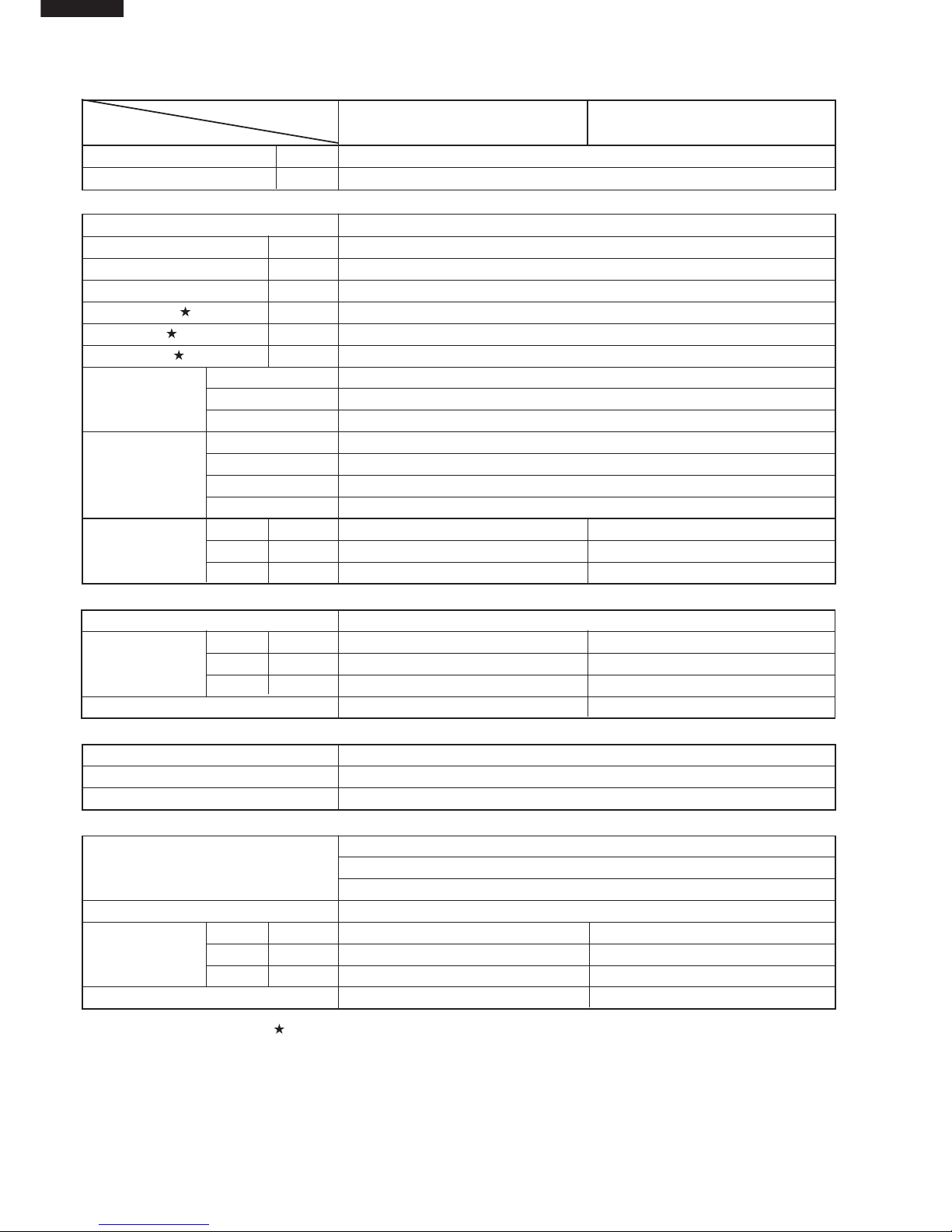
SPECIFICATIONS
MODEL
INDOOR UNI
T OUTDOOR UNIT INDOOR UNIT OUTDOOR UNIT
ITEM AH-MX122 AU-MX122 AH-MX152 AU-MX152
Cooling capacity(Min. ~ Max.) BTU/h 9000(3600~12000)
11700(5400~15000)
Moisture removalLiters/h 0.7 0.7
Electrical data
Phase Single
Rated frequencyHz 50
Rated voltage range V 198 to 242
Rated voltage V 220
Rated current A 4.2 5.5
Rated input W 818 1090
Power factor % 89 90
Type AC Single Rotary
CompressorModel 44A072QV2DJ HV187XV-S12F3
Oil charge SUNISO 4GDID 280cm3 SUNISO 4GDID 370cm
3
Evaporator Louver Fin and Grooved tube type , Pre-coat treament
Refrigerant system
Condenser Louver Fin and Grooved tube type
Control Capillary tube
Refrigerant volume
50g 740g 50g 800g
Noise level
HighdB(A) 36 43 40 48
(at cooling)
Med.dB(A) 32 43 35 48
LowdB(A) 27 43 29 48
Fan system
Drive Direct drive
Air flow quantityHighm3/min. 9.8 30 10.5 30
(at cooling)Med.m3/min. 8.8 30 9.5 30
Lowm3/min. 6.4 30 6.6 30
Fan Cross flow fan Propeller fan Cross flow fan Propeller fan
Connections
Refrigerant coupling Flare type
Refrigerant tube size Gas, Liquid 3/8", 1/4" 3/8", 1/4" 1/2", 1/4" 1/2", 1/4"
Drain piping mm O.D ø 18 - O.D
∅
18 -
Others
Compressor: Thermal protector
Safety device Fan motors: Thermal fuse
Fuse, Micro computer control
Air filters Polypropylene net (Washable)
Widthmm 815 780 815 780
Net dimensionsHeightmm 278 550 278 550
Depthmm 198 269 198 269
Net weightkg 9 33 10 38
Note: The condition of star " " marked item are ‘ISO5151’ : 1994(E), condition T1.
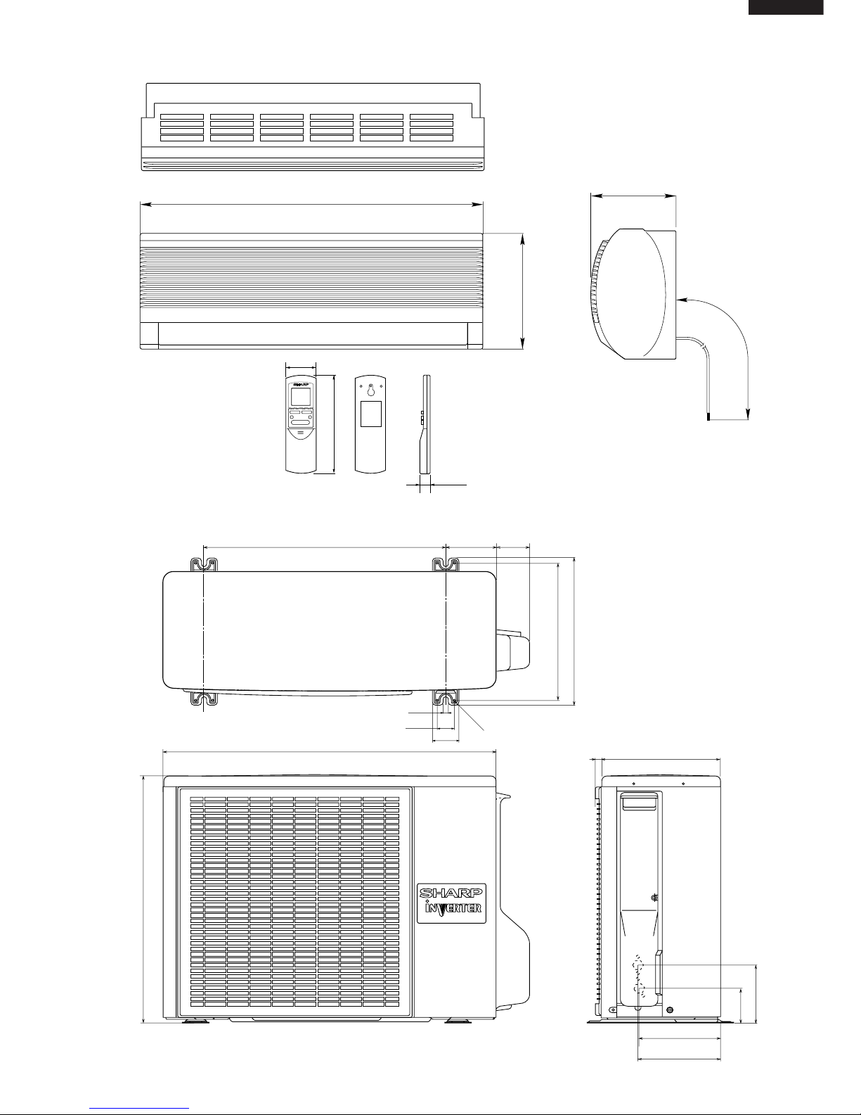
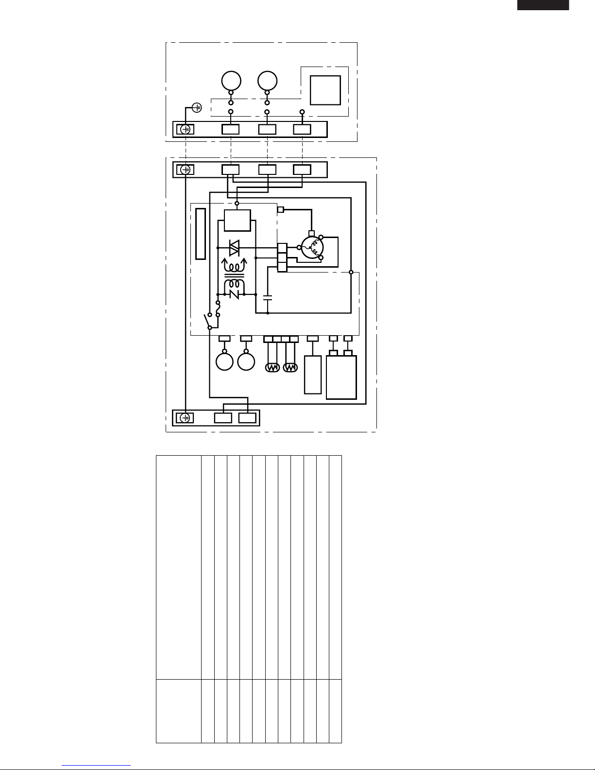
EXTERNAL DIMENSIONS
INDOOR UNIT
OUTDOOR UNIT
Length unit (mm)
19.5
58
CRMC-A442JBE0
R03(AAA) 2PCS.
SHARP CORPORATION
INVERTER AIR CONDITIONER
182
815
278
198
1100
269
179.5
182.5
136
81
780
70
540
310
335
540
12
37.5
4.5
58
158
16
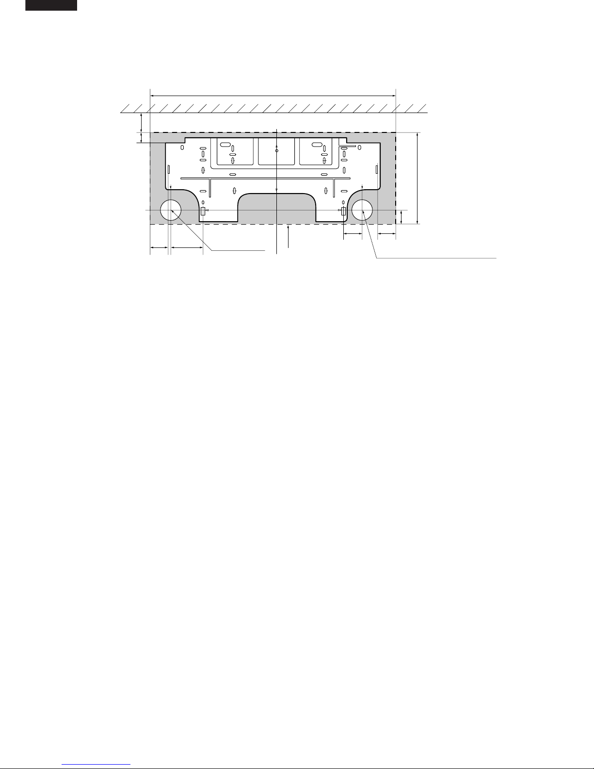
INSTALLATION DIMENSIONS
815 (unit size)
More than 50mm
E
Center of wall hole:
Leftward piping
Center of wall hole: Backward piping
Outline of indoor unit
55 95
80 55
AJ
IF
E
D
D
FA
C
J
H
I
GB
21
278 (unit size)
38
Ceiling
E
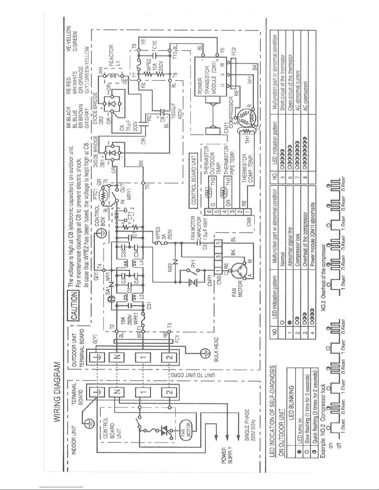
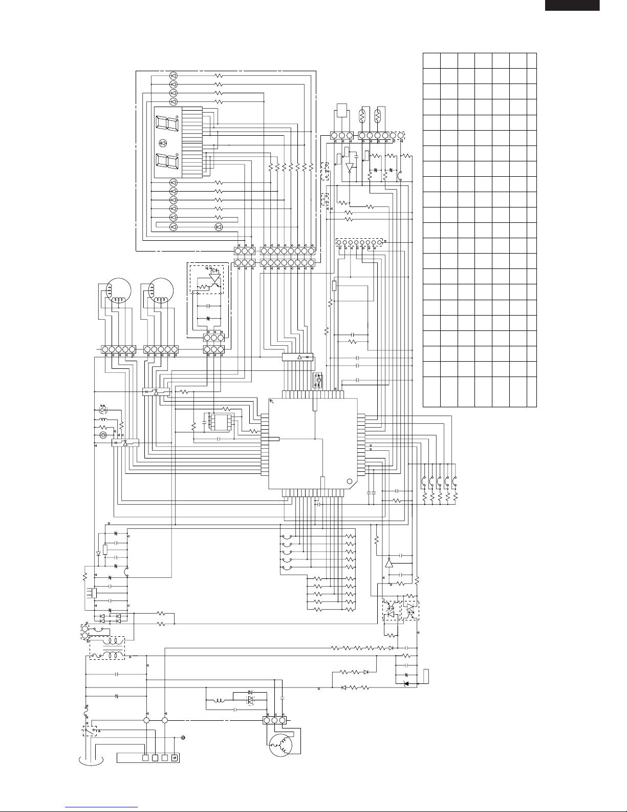
Wiring Diagram for AH-MX122 / AH-MX152
WIRING DIAGRAMS
TERMINAL BOARD 1
GREEN-YELLOW
POWER
SUPPLY
SINGLE
PHASE
INDOOR UNIT
OUTDOOR UNIT
BROWN In Out
C1
RY1
WPE1
250V
3A
CONTROL BOARD UNIT
LOUVER
(UPPER)
LOUVER
(LOWER)
ROOM TEMP.
THERMISTOR
PIPE TEMP.
THERMISTOR
TH1
TH2
341
2
CN3
YELLOW
ORANGE
RECEIVER
BOARD UNIT
DISPLAY
BOARD
UNIT
BCN2
BCN3
CN101
CN102
CN2
CN7
BCN1
TRANS1
SSR1
S
SERIAL
SIGNAL
CIRCUIT
FAN MOTOR
CAPACITOR
430V 2µF
CN6
CN1
TERMINAL BOARD 2
TERMINAL BOARD
BLACK
RED
BLUE
BLUE
5
3
1
N
BLACK
FAN MOTOR
BLUE
RED
COMPRESSOR
FAN MOTOR
UNITTOUNIT
CORD
CONTROL
BOARD
UNIT
N
1
11
NN
22
R.P.M.
SIGNAL
INTERNAL
THERMAL
FUSE
LED INDICATION FOR SELF-DIAGNOSIS
Abnormal contents
Temperature
Indicator
Blinking No.
1
2
3
4
5
6
7
141718
19
Short circuit of the outdoor thermistor
Overheat of the compressor
Abnormal AC current
Compressor lock
Open circuit of the outdoor thermistor
AC overcurrent
Power module
(
IPM
)
abnormality
Open circuit of serial signal line
Short circuit of serial signal line
Abnormal fan motor of indoor unit
Abnormal power factor module
(
AFM
)
< Indication of the abnormal condition >
LED indicator will blink, if the set
is in abnormal condition.
M
M
M
M
Electronic Control Circuit Diagram for AU-MX122
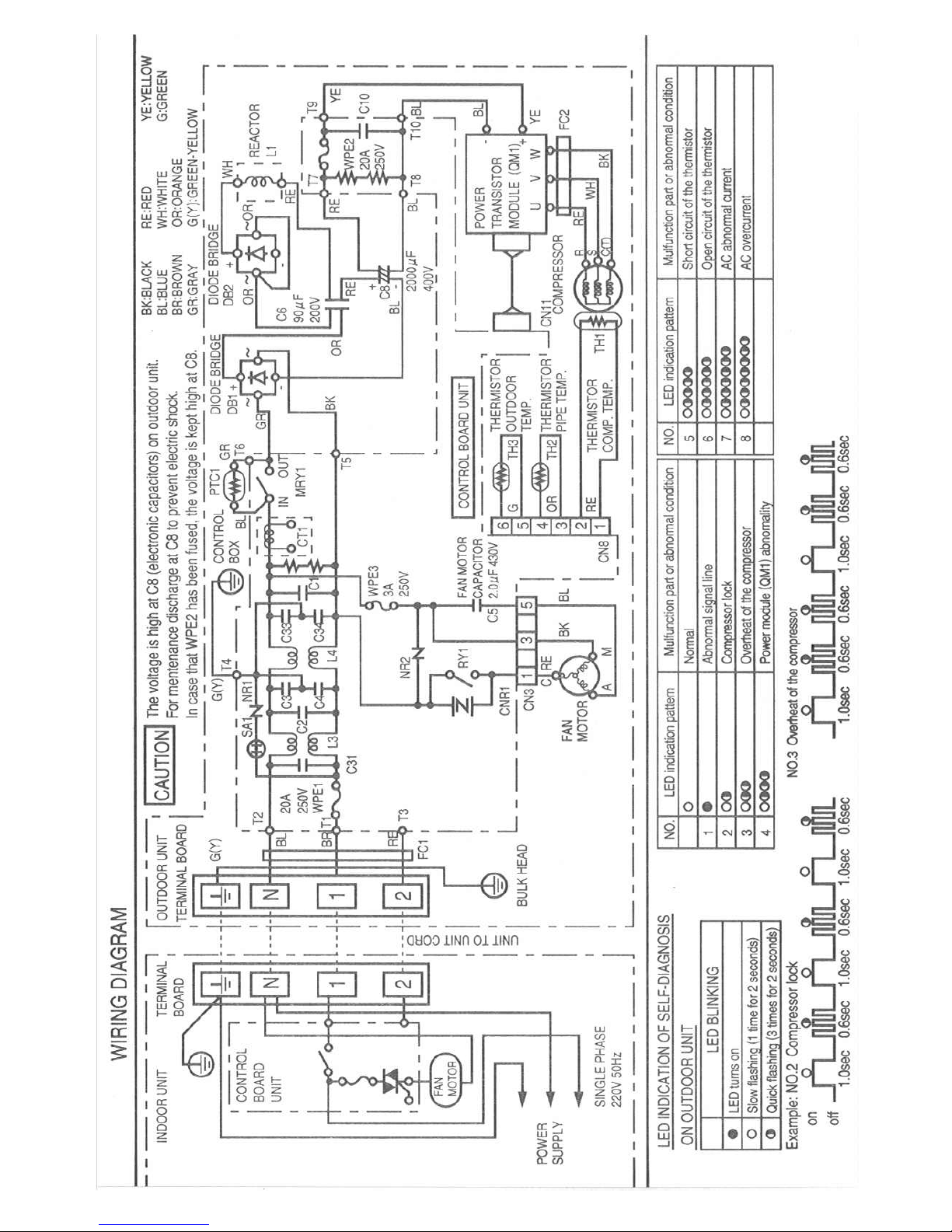
Electronic Control Circuit Diagram for AU-MX152
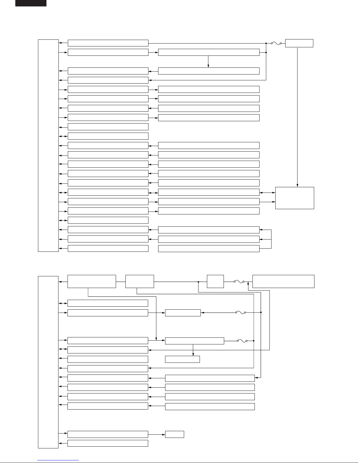
BLOCK DIAGRAMS
INDOOR UNIT
AC power
CPU
3 A
WPE1
DC power supply circuit
Fan motor phase control circuit
Rotation pulse input circuit
AC clock circuit
Louvre motor drive circuit(upper)
Louvre motor drive circuit(lower)
Remote controller signal reception circuit
Buzzer drive circuit
CPU reset circuit
CPU oscillator circuit
Room temp. detect circuit
Heat exchanger pipe thermo circuit
Compensation circuit/ select circuit
Compensation circuit
Switchover circuit
Serial I/O circuit
Compressor relay drive circuit
LED drive circuit
Auto restart circuit
Test run circuit
Auxiliary mode
Power on circuit
Room fan motor
Fan motor pulse detect
Flow direction control (louver motor upper)
Flow direction control (louver motor lower)
Wireless remote control operation
Audible operation confirmation
Room temp. thermistor
Heat exchanger pipe thermistor
Blower temperature, fan speed, model select
Outdoor ratings
Wireless, preheat
Indoor/outdoor control signal I/O
Outdoor unit power supply on/off control
LED display
Test run (forced operation)
Auxiliary mode button ON/OFF
Self diagnostics, fault diagnosis
Unit-unit wiring
(AC power and
serial signals)
CPU
15 A
protection
Outdoor fan
4-way valve
Power transistor module
Compressor
Current transformer
Compressor thermistor
Heat exchanger pipe thermistor
Outdoor temperature thermistor
Heat exchanger pipe thermistor(option)
Outdoor temperature thermistor(option)
LED
3 A
protection
10 A
protection
Power supply circuit
(built into IPM)
CPU oscillator circuit
Outdoor fan relay drive circuit
4-way valve relay drive circuit
Power transistor module drive circuit
Serial I/O circuit
CPU reset circuit
DC overcurrent detection circuit
AC overcurrent detection circuit
Compressor thermo circuit
Heat exchanger pipe thermo circuit
Outdoor temp. thermo. circuit
Winter kit circuit (option)
LED drive circuit
Test mode circuit
Filter
circuit
Smoothing
circuit
Unit-unit wiring (AC power
and serial signals)
OUTDOOR UNIT
MICROCOMPUTER CONTROL SYSTEM
Electronic Control Circuit Diagram for AH-MX122 and AH-MX152
(CN9)
LED101
LED104
LED103
LED102
LED110
LED109
LED108
LED107
LED106
LED105
R101
R102
R103
R104
R105
R106
R107
R108
R109
1/2W
1/2W
1/2W
1/2W
220
220
300
220
220
220
220
220
100
1/2W
1/2W
1/2W
1/2W
1/2W
LED111
1/2W
1/2W
1/2W
330
R114
R40
3.3K
50V
50V
C21
C22 1000p
1000p
BCN3
BCN2
R58~R62
(SW2)
MOTOR
FAN
IC
HOLE
321
P00
P01
P02
P03
P04
P05
P06
P07
P10
P11
P12
P13
P14
P16
P17 33
34
35
36
37
38
39
40
41
42
43
44
45
46
47
48
52535455565758596061626364 P63
P64
P65
P66
P67
AVss
Vref
Vcc
P30
P31
P32
P33
P34
515049
P35
P36
P20
P21
P22
323130
P23
P24
P25
P26
P27
Vss
Xout
Xin
P40
P41
RESET
CNVss(Vpp)
P42
29282726252423222120191817
P62
P61
P60
P57
P56
P55
P54
P53
P52
P51
P50
P45
P43
1
2
3
4
5
6
7
8
9
10
11
12
13
14
15
16
NC
M3803**
IC1
(PATTERN SIDE)
PC2
PC1
4
2
4
3
1
2
4.7K
100K
+
0.047µ
50V
250V
0.01µ
680 680
2W 2W
680 680
2W 2W
680
2W
22K
P15
1
10K
10K
0.1µ
25V
8M
65432
1
PIPE TEMP.
TH2
10kΩ(25˚C)
15kΩ(25˚C)
ROOM TEMP.
TH1
C2
0.22µ
250V
NR1
IN
T
250V
OUT
RY1
WPE
N
N
2S
1
UNIT
OUTDOOR
TO
TERMINAL
BOARD
KID65783AP
IC6
10
SW1
5V
GND
12V
-24V
33K
33K
33K
33K
33K
16V
C26
0.01µ
R41
1.8K
33K
33K
33K
1000P
3
2
3
1
2
R23
3.3K
CN6
100µ
C810V
+
FAN L
FAN M
FAN H
RATE HEAT
TEA
MODEL 5
MODEL 4
MODEL 3
MODEL 2
MADEL 1
R42
R43
R44
R45
R46
R47
R48
R49
R50
R51
R52
R53
R54
R55
R56
JP 1
JP 2
JP 3
JP 4
JP 5
R67 R66
12K 12K
2W
D9
D8
R65R64
11K
2W 2W
11K
2W
C30
100µ
35V
C29
ZD1
R63
C28
D7
R57
C27
R38
R37
R36
R35
R34
JP8
JP7
JP6
R30
380
R29
680
C19
+
+
C18
10µ
16V16V
10µ
10K
(F)
R27
10K
(F)
R26
R21
R20
R19
C13
C12
C11
IC7
IC8
OSC1
FRONT
1/2W
R9
R8
C9
C10
1000p
50V
25V
0.1µ
R5
RY1
R4
BZ1
BUSY112V25V
3
4
CLOCK5SERIAL
OE
6
7
RESET
GND
8
HOT KEEP
PREHEAT
WIRELESS
2.7K
50V
1000p
1000p
50V
P37
P44
P46
P47
4
3
2
1
7
6
5
8
1
1K
FUSE
THERMAL
SSR1
470
1.8K
16
9
10K
3
1
POWER
SUPPLY
SINGLE
PHASE
21
JP10
33KR2
TRANS1
D1~4
33K
R3
+
C450V
0.1µ
7812
IC2
35V C3
1000µ
IN
0.1µ
25V
OUT
C5
+
47µ
25V
100 1/2W
R1
JP11
+
C6
25V
47µ
0.1µ
25V C7
IN
IC3
D5
7805
25V
0.1µ
R31
IC4
8
NC
9
118
13
11
C31
250V 0.01µ
SSR1
CNR1
L1
430V
C1
2µ
FUSE
THERMAL
MOTOR
FAN
531
CN1
C32
C33
680
R6
CN101
22
33
11
88
11
2233445566
77
CN102
NC
NC
10(B2)
11(A2)
12(F2)
15(B1)
18(F1)
17(G1)
16(A1)
14(CM1)
13(CM2)
9(H2)
8(C2)
7(G2)
6(D2)
5(E2)
4(H1)
3(C1)
2(D1)
1(E1)
H2
H1
CM1,2
D2
G2
A2
E2
F2
B2
C2
D1
G1
A1
C1
B1
E1
F1
33K
33K
R33
R32
JP9
JP99
TEST
POWE ON
R39
20K
C24 16V
0.01µ
1
3
2
C2550V
1000P
330
W115
1/2W
LED121
R1163301/2W
1/2W
R111
330
R112
R110
330
330
1/2W R113330
25V
0.1µ
680
680
Q1
Q2
R68
R69
3A
33K
CN7
0.1µ
25V
33µ
10V
+
5V
GND
C201
C202
IC201
BCN201
BCN1
11
33
22
6.8K
8
IC59
1
16
10K
R7
CN3
12345
LOUVER
MOTOR
UPPER
LOWER
LOUVER
MOTOR
4
5
1
CN2
2
3
∆ :TEST POINT
(NOTE)
LED101 : OPERATION
LED102 : TIMER
LED103 : ROOM TEMP.
LED104 : OUTDOOR TEMP.
SW1 : AUX.(TEST RUN)
SW2 : POWER SELECTION
LED105 : POWER MONITOR ECO
LED106 : POWER MONITOR 1
LED107 : POWER MONITOR 2
LED108 : POWER MONITOR 3
LED109 : POWER MONITOR 4
LED110 : POWER MONITOR POWER
HL
50V
C34
JP34
C1716V
0.01µ
JP23680
NONEUSE
SW2
USE
NONE
NONENONE NONENONEUSE
15K13K13K 15K15K13K13K15K13K
NONE NONE USENONE NONE NONENONE
USEUSENONE NONENONENONE USENONENONE
13K 15K 13K 13K 15K 15K13K 13K 15K
USE NONE NONE
NONENONEUSEUSE
15K13K13K 15K15K13K13K15K13K
NONE NONE USENONE NONE NONENONE NONE
NONENONENONE NONENONENONE USEUSENONENONENONE
13K 24K 15K13K 13K 15K 15K13K 13K 130K
AH-MX122
AH-MX152
AH-X10BE
AY-X08BE
AH-MX152
AH-MX122
MODEL
JP1 JP2 JP3 JP4 JP5 JP6 JP7 JP8 JP9 R51R50R49R48R47R46R45R44R43R42JP99
68K13K13K 15K15K13K13K ----47K13K
NONEUSE USE NONE USE NONE NONE USE NONE NONE
33K13K13K 2.4K3.6K13K----- 15K15K13K
USE NONE USE NONE USENONE NONE NONE
 Loading...