

Page 1
SERVICE MANUAL
Page
SPLIT SYSTEM
ROOM AIR CONDITIONER
INDOOR UNIT OUTDOOR UNIT
AH-129 AU-129
AH-MP14 AU-MP14
CONTENTS
SPECIFICATIONS..............................................................................................................................................2
EXTERNAL DIMENSIONS.................................................................................................................................4
WIRING DIAGRAMS..........................................................................................................................................5
ELECTRICAL PARTS........................................................................................................................................6
MICROCOMPUTER CONTROL SYSTEM.........................................................................................................7
PRINTED WIRING DIAGRAM............................................................................................................................8
FUNTIONS........................................................................................................................................................10
TROUBLESHOOTING......................................................................................................................................14
REFRIGERATION CYCLE AND PERFORMANCE CURVES..........................................................................16
DISASSEMBLING PROCEDURE.....................................................................................................................17
REPLACEMENT PARTS LIST..........................................................................................................................25
SHARP CORPORATION
SHARP CORPORATION
1
Page 2
CHAPTER 1. PRODUCT SPECIFICATION
A
y
g
g
g
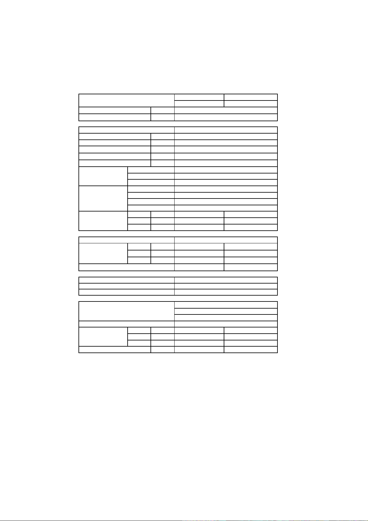
[1] SPECIFICATION
1. AH-129 / AU-129
ITEMS
Cooling capacity kW 3.50
Moisture removal Liters/h
Electrical data
Phase Single
Rated frequency Hz
Rated voltage V 220
Rated current
Rated input * W 1090
Power factor % 97 - 99
Compressor Type Hermetically sealed rotary type
Model RH207VXGT
Oil charge 520cc (DIAMOND MS56)
Refrigerant system Evaporator Slit fin and Grooved tube type
Condenser Slit fin and Grooved tube type
Control Capillary tube
Refrigerant volume 960g
Noise level
stem
Fan s
Drive Direct drive
Air flow quantity
Fan
Connections
erant couplin
Refri
erant tube size Gas, Liquid 3/8" , 1/4"
Refri
Drain piping
Others
Safety device Compressor : Internal protector
Air filters Polypropylene net (Washable)
Net dimensions
Net weight
High
Mid.
Low
High
Mid.
Low
Width
Height
Depth
A5.1
dB(A)
dB(A)
dB(A)
m3/min.
m3/min.
m3/min.
mm O.D 18
mm
mm
mm
kg
INDOOR UNIT
H-129
–
50
39
33
29
10.2
9.6 –
8.7
Cross flow fan
Flare type
φ
Fan motor : Thermal fuse / Protector
Fuse, Micro computer control
790
278
198
10
OUTDOOR UNIT
48
–
–
27
–
Propeller fan
730
540
250
34
AU-129
2
Page 3

2. AH-MP14 / AU-MP14
A
y
/
g
g
g
ITEMS
INDOOR UNIT
H-MP14
OUTDOOR UNIT
Cooling capacity kW 3.50
Moisture removal Liters/h
–
Electrical data
Phase
Rated frequency Hz
Single
50
Rated voltage V 220
Rated current A5.1
Rated input * W 1090
Power factor % 97 - 99
Compressor Type Hermetic al l y sealed rotary type
Model RH207VXGT
Oil charge 520cc (DIAMOND MS56)
Refrigerant system Evaporator Slit fin and Grooved tube type
Condenser Slit fin and Grooved tube type
Control Capillary tube
Refrigerant volume 960g
Noise level
stem
Fan s
Drive
Air flow quantity
Fan
High
Mid.
Low
High
Mid.
Low
dB(A)
dB(A)
dB(A)
m3/min.
m3/min.
m3
min.
39
33
29
Direct drive
10.2
9.6
8.7
Cross flow fan
48
–
–
27
–
–
Propeller fan
Connections
erant couplin
Refri
erant tube size Gas, Liquid 3/8" , 1/4"
Refri
Drain piping
mm O.D 18
Flare type
φ
φφ
Others
Safety device
Compressor : Internal protector
Fan motor : Thermal fuse / Protector
Fuse, Micro computer cont rol
Air filters Polypropylene net (Was habl e)
Net dimensions
Net weight
Width
Height
Depth
mm
mm
mm
kg
790
278
198
10
730
540
250
34
AU-MP14
3
Page 4

[2] EXTERNAL DIMENSION
1. Indoor unit (AH-129 / AH-MP14)
2. Outdoor unit (AU-129 / AU-MP14)
198790
278
540
515
730
37.5
12
58
135
4.5
72
299
324
14
250
165
167.5
81
136
4
Page 5
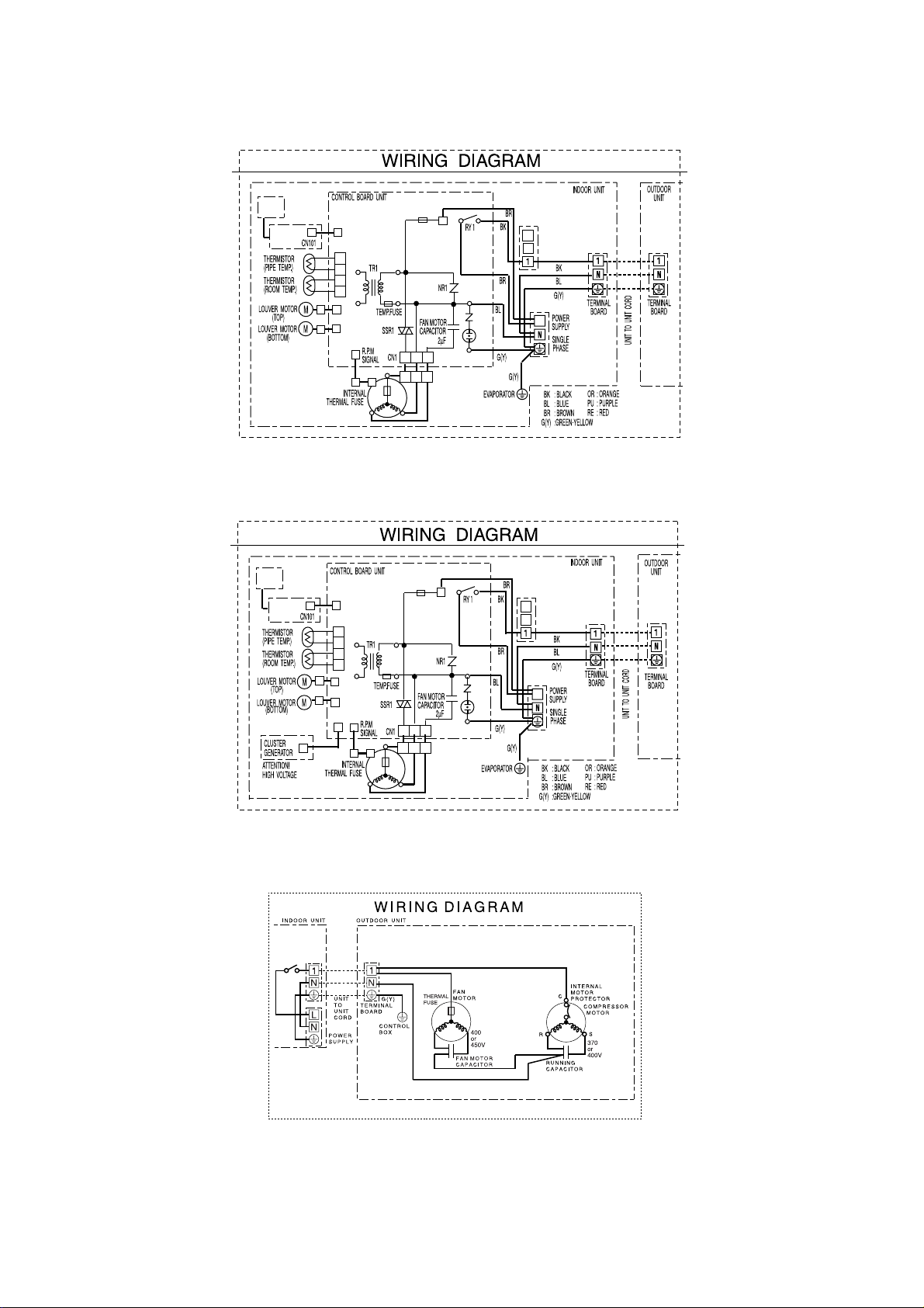
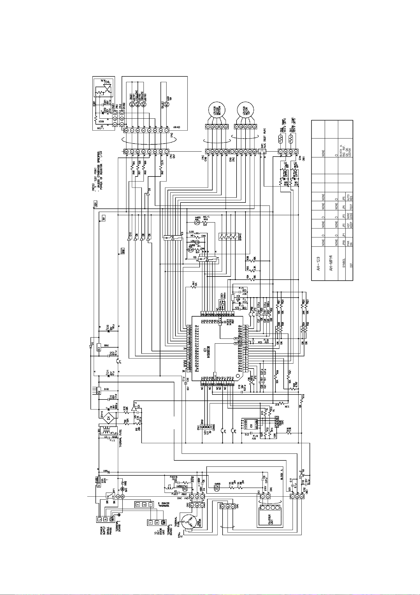
[3] WIRING DIAGRAM
Indoor Unit (AH-129)
4'%'+8'4
70+6
&+52.#;
70+6
Indoor Unit (AH-MP14)
4'%'+8'4
70+6
&+52.#;
70+6
%0
%0
%0
%0
%0
(#0/1614
%0
%0
%0
%0
%0
%0
1WV
6'4/+0#.
$1#4&
.'(6
#
8
(75'
6
+P
#
04
8
5#
)
.
6'4/+0#.
$1#4&
.'(6
4+)*6
%%
04
5#
1WV
6'4/+0#.
$1#4&
.'(6
6'4/+0#.
$1#4&
.'(6
.
4+)*6
#
8
6
+P
(75'
#
8
)
(#0/1614
Outdoor (AU-129 / AU-MP14)
$-$.#%$.$.7'
$4$4190
4'4'&
9*9*+6'
);)4''0;'..19
%%
4'
$-
$.
Ǵ(
$-
4'
$4
9*
Ǵ(
$.
%%
5
Page 6
CHAPTER 2. ELECTRIC CIRCUIT
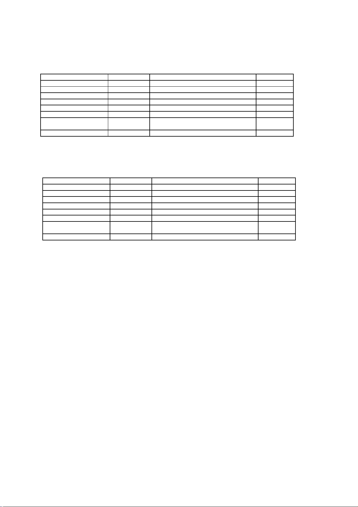
[1] ELECTRIC PARTS
1. AH-129 / AU-129
DESCRIPTION
Compressor
Indoor fan motor CMOT-A448JBKZ 220 - 240V , 50Hz INDOOR
Outdoor fan motor
Indoor fan motor capacitor
Outdoor fan motor capacitor
Running capacitor
Transformer — Primary ; AC 220 / 240V 50Hz
Fuse — 250V, 2.5A INDOOR
2. AH-MP14 / AU-MP14
DESCRIPTION
Compressor
Indoor fan motor CMOT-A448JBKZ 220 - 240V , 50Hz INDOOR
Outdoor fan motor
Indoor fan motor capacitor
Outdoor fan motor capacitor
Running capacitor
Transformer — Primary ; AC 220 / 240V 50Hz
Fuse
MODEL
RH207VXGT 220V, 50Hz, 1120W
CMOTLB182JBEZ 220 - 240V , 50/60Hz
— 450V, 2
— 400V, 2
— 400V, 30µF
—
MODEL
RH207VXGT 220V, 50Hz, 1120W
CMOTLB182JBEZ 220 - 240V , 50/60Hz
— 450V, 2
— 400V, 2
— 400V, 30µF
—
— 250V, 2.5A INDOOR
µF INDOOR
µF
Secondary ; AC15.3V , 50Hz
µF INDOOR
µF
Secondary ; AC15.3V , 50Hz
REMARKS
REMARKS
SITE
OUTDOOR
OUTDOOR
OUTDOOR
OUTDOOR
INDOOR
SITE
OUTDOOR
OUTDOOR
OUTDOOR
OUTDOOR
INDOOR
6
Page 7
[2] MICRO-COMPUTER CONTROL SYSTEM
1. Electronic Control Diagram
Indoor unit (AH-129 / AH-MP14)
7
Page 8
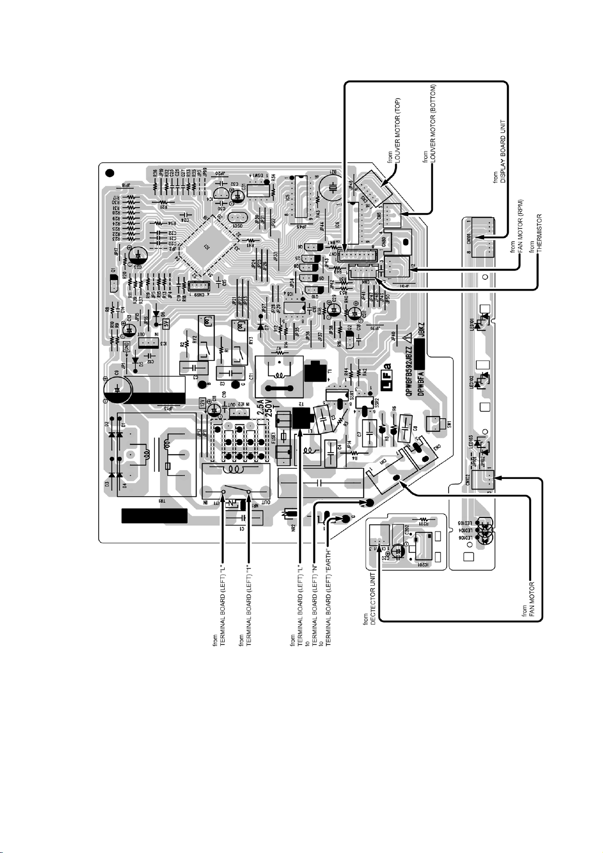
2. PRINTED WIRING DIAGRAM
2.1 Indoor (AH-129)
8
Page 9

2.2 Indoor (AH-MP14)
9
Page 10

CHAPTER 3. FUNCTIONS
p
)
p
)
p
)
[1] FUNCTION
TEMPERATURE CONTROL
CHARACTERISTIC
In the "COOL" mode, the thermostat circuit is controlled by five
thermostat lines (C1 thru C5).
1.2. DRY
In the "DRY" mode, the thermostat circuit is controlled by three
thermostat lines (D1 thru D3).
1.1. COOL operation
18 32
Preset temperature (C )
2.2. DRY
On the switch on, the compressor always starts to operate for 2
minutes with fan speed "DL".
The microcomputer reads the room temperature 2 minutes after
this first compressor operation.
This room temperature is set as the preset temperature
The preset temperature ranges from 18 C to 32 C. When the room
temperature is below 18 C, the preset temperature is set to 18 C,
and when the room temperature is over 32 C, the preset
temperature is set to 32 C.
Dry operation is divided into three zones (Cooling zone,
Dehumidifying zone and Circulating zone) by thermostat lines (D1
to D3), and the compressor and the fan motor are controlled in
each zone as shown in Table.
°°
18 32
Preset tem
erature (C
OPERATION MODES
2.1. COOL operation
The compressor turns on or off, at the thermostat lines C3 and
C4. The outdoor fan motor is also controlled with the compressor.
18 32
Preset tem
Cooling zone (1) & (5) ON "DH"
Dehumidifying zone (2) & (4) ON "DL"
Circulating zone (3) OFF "DL" or OFF
erature (C
Compressor Fan speed
FAN SPEED
Fan speeds are given by the indoor fan motor, "DL"~"CH" which
are available in the following operation mode.
NOTE: Fan speed may be changed, without warning.
Fan
Fan switch Fan switch
speed
DL
DH
CL
CAL
CM
CAH
CH
—
—
COOL LOW — 800
—
COOL MID
—
COOL HIGH — 1170
(AUTO)
DRY
COOL
AH-129 / AH-MP14
(r.p.m)
800
890
840
980
1020
FREEZE PREVENTIVE
When the indoor pipe temperature falls below 3 C cool or dry
operation for 3 minutes or more, the compressor is turned off.
When the indoor pipe temperature rises above 7 C in cool or dry
operation for 3 minutes or more, the compressor is turned on.
°
18 32
Preset tem
erature (C
10
Page 11

TEST RUN OUTPUTS IN EACH OPERATION MODE
p
)
p
If the "AUX" button on the unit is pressed for 5 seconds or more
during operation, cool test operation starts. The operation LED (red)
flickers during tes t run.
In cool mode continuous compressor on operation is performed. In
dry mode the operation is in dehumidifying zone.
TIMER
6.1. ON/OFF Timer
When the unit operates duri ng one hour after the OFF-time is s et, tem-
°°°
+0.33 C +0.66 C +1 C
erature setting is automatically shifted ( in
(After 1H) (After 1.5H) (Aft er 2H)
operation and dry operation). When the ON-timer is set in cool
operation, operation starts before 0 to 30 minutes(depends on the
room temperature
so that preset tem perat ure i s obtaind at set time.
6.2. 1 hour timer
When ONE-HOUR timer is set, the unit turns off automatically afte
one hour. The one hour timer operation has priority over other time
r
operation, such as the TIMER ON and TIMER OFF. If the
ONE-HOUR TIMER button is pressed again duri ng operation, the unit
AUTOMATIC AIR CONDITIONING
When autom atic air conditioning is selected, the operation mode and
preset temperature are set automatically according to the room
temperature on starting operation.
Room temperature
eration start
at o
Above 28
26
24
Below 24
°C26°C
°C > 28°C COOL 25°C
°C > 26°C24°C
°C DRY Room temperature at
When DRY mode is selected by the micro computer with AUTO
operation, the fan speed lamps on the indoor unit panel will indicate
identically with the fan speed symbols on the remote control dispaly,
as the FAN speed setting i s changed accordingly. Despit e,
Operation Mode Preset Temperature
operation start
Mode
Cooling ON ON ON OFF
O
Circulat-
O
ing
U
Cooling ON
}
Dehumidiflying
o
Circulating
POWER ON START
If the connecting wire "POWER ON" (JP99) is cut on the PWB
ass'y, when the power is supplied by t urning on a circuit breaker,
the air conditioner automat i c al l y s tarts of operation in "AUTO".
(Refer to Printed Wiring Board.)
AUTO RESTART
11.1. When JP5 is ON
Power failuer occurs during operation, the unit will restart in the
same operation mode as bef ore recovery.
11.2. When JP5 is OFF
Auto restart funct i on i s not available.
Compres-
sor
Outdoor
Fan Motor
Indoor
Fan Motor
OFF OFF ON OFF
ON L/UL
ON ON UL/D OFF
OFF OFF D/OFF OFF
Valve Coil
OFF
AUTOMATIC FAN SPEED
When the automatic fan speed is selected in cool operation, the fan
speed is automatically changed by the thermostat lines C1 to C3 in
cool operation.
11
Page 12

[2] TEST MODE
1. AH-129
Keep pushing the "AUX." buttons and supply the power, the system will go to the test mode. In this mode, the output of operation is switched by
pushing the ""AUX." button in the unit or the "OI" button in the remote controller. Normal outputs are shown in Table.
STEP No.
BUZZER
STEP0
STEP1
STEP2
STEP3
STEP4
STEP5
STEP6
STEP7
STEP8
STEP9
STEP10
BEEP2
BEEP1
BEEP1
BEEP1
BEEP1
BEEP1
BEEP1
BEEP1
BEEP1
BEEP1
BEEP1
OUTPUT "-" : NO CHECK, "O" : ON, "X" : OFF
LED 101 LED 102 LED 103
RED YELLOW GREEN
O *1O*2O
X X O
O RPM X O
O *4 X
O IC8 O O
OOO
X R.C. X O
XXX
XXO
O X O
O O O
LED 104
BLUE
X
X
X
X
X
X
X
X
X
X
X
FAN
LOUVER OUTDOOR
MOTOR
XXX
O OPEN O
O X X
O X O
O X X
OXO
O X X
OXO
OXX
O X O
X CLOSE O
*1 : 7°C<(ROOM TEMP.)<42°C
°C<(PIPE TEMP.)<45°C
*2 : -2
*4 : O --- POWER ON INVALIDITY
*4 : X --- POWER ON VALIDITY
1. AH-MP14
STEP No. OUTPUT "-" : NO CHECK, "O" : ON, "X" : OFF
BUZZER
STEP0
STEP1
STEP2
STEP3
STEP4
BEEP2
BEEP1
BEEP1
BEEP1
BEEP1
LED 101 LED 102 LED 103
RED YELLOW GREEN
O *1O*2O
X X O
O RPMO O
O *4 X
O IC8O O
LED 104
BLUE
O
X
O
X
X
STEP5BEEP1 X O O X OXOX
STEP6
STEP7
STEP8
STEP9
STEP10
BEEP1
BEEP1
BEEP1
BEEP1
BEEP1
X R.C.X O
X X X
XXO
O X O
O O O
X
X
X
X
X
FAN
LOUVER OUTDOOR PLASMA
MOTOR
CLUSTER
XXXX
O OPEN O X
OXXO
O X O O *4 : O --- POWER ON INVALIDITY
OXXX
OXXX
OXOX
OXXX
OXOX
X CLOSE O X
*1 : 7°C<(ROOM TEMP.)<42°C
°C<(PIPE TEMP.)<45°C
*2 : -2
*4 : X --- POWER ON VALIDITY
12
Page 13

[3] DIAGNOSIS PROCEDURE
1. AH-129 / AH-MP14
When indoor fan m ot or i s out of order occurs, indoor fan motor and louver are all stopped and the operation LED(red) turns on or off
synchronously with the tim i mg of the timer LED.
When the therm i stor for room tem perat ure or pipe temperature is open or short state, the operation LED t urns on or off synchrnoously with the
timing of the timer LED by pushing continous l y f or more than 5 seconds "AUX." but ton during suspension of operati
Timing chart of Tim er LED and Operation LED of DIAGNOSIS P ROCE DURE .
When "OI" button the remote controll er or " A UX." but ton in the unit is pushed, the unit is free from DIAGNOSIS
When the louver unit is not properly inst alled, all lamps on the indicator panel will blink operation are all stop and Remote signal is not acc ept .
13
Page 14

CHAPTER 4. TROUBLESHOOTING
14
Page 15

CHAPTER 4. TROUBLESHOOTING
15
Page 16

16
Page 17

DISASSEMBLING PROCEDURE MODEL: AH-129 ,AH-MP14
[1] INDOOR UNIT
Be sure to disconnect t he power supply cord from the AC power outlet before starting the disass embly procedure. W hen reassembling the unitafter repairing, besure to install screws to their original positions.
The screws used are not the same i n specifications s uch as corrosion-resist ant treatment, ti p shape and length.
After the air conditioner i s repaired or parts or replaced, measure insulation resist ance of the equipment using and i nsulation resistanc e meter.
if the measured resistance is lower than 1M , inspect parts and repair or replace defective parts.
1) Open the open panel. 5) Pushing the 2 hooks, dis connect the louver base(2)
2) Remove screw fixing the cord clamp.
Ω
6) Remove 2 air filters.
3) Remove the cord clam p. 7) Remove the Screw cover (use the(-)driver).
4) Remove the unit-to-unit wiring from the terminal board(4). 8) Remove the cover.
17
Page 18

9) Remove 5 screws fixing the front panel. 14) Remove the control box.
10) Pull the front panel up.
11) Remove a screw fixing the Control box cover,
and remove it 15) Remove the LED guide.
16) Pushing the 2 hooks of the hol der, remove the display
12) Remove the 2 screws fixing the cont rol box. board
13) Disconnect the thermistor. 17) Remove a screw fixing the holder.
18
Page 19

18) Remove the holder. 21) Remove the screw fixing the evaporator ass 'y and -
evaporator.
22) Remove the drain guide.
19) Remove 2 screws fixing the holder. (AH-MP14)
23) Remove 2 screws fixing the evaporator.
20) Remove 2 screws fixing the PC cover. (AH-MP14)
24) Remove 2 screw fixing the evaporator and bushing holder.
19
Page 20

25) Pull the evaporator ass'y up. 28) Remove the screw fixing cross flow fan.
26) Take out the left side of the drain pan.
29) Hold up the left side of evaporator, pull out cross flow
fan
Attention: In cas e of assembly.
Part A is inserted into the drain part of the drain pan.
27) Take out the right side of t he drai n pan l eavi ng drai n-
hose in cabinet.
20
Page 21

MODEL: AU-129 ,AU-MP14
[2] OUTDOOR UNIT
1) Loose a screw fixing the side cover 3) Loose the unit-to-unit cord.
2) Loose 2 screws fixing the terminal cover and 1 screw- 4) Loose 6 screws fixing the top panel.
fixing the cord clamp. ( Right side view )
21
Page 22

( Left side view ) 5) Loose 5 screws fixing the front panel. (Ri ght side view)
( Left side view )
( Front view )
( Front view )
22
Page 23

6) Cut 3 plastic bands. 9) Remove 3 terminals of compressor.
7) Remove 2 terminals. (connecting with fan condenser) 10) Loose 4 screw fixing the control box.
8) Remove the terminal cover.
11) Take out the control box
23
Page 24

1. DISASSEMBLING PROCEDURE OF THE FAN 2. ASSEMBLING PROCEDURE OF COMPRESSOR
COVER
1) Loose the fan nut and take out f an. 1) Remove: Unlace the fastenner and pull the compress or cover
out from left side. [a) b)]
2) Assembly: Insert the compressor cover from left side, cover
the tube and fasten. [b) a)]
2) Loose 4 screws fixing fan motor.
24
 Loading...