

Page 1
AF-W12CME
ROOM AIR CONDITIONER
INSTALLATION AND OPERATION
MANUAL
CONTENTS
PAGE
OPERATION INSTRUCTIONS
• PRECAUTIONS ........................................ 2
• ADDITIONAL NOTES ON OPERATION .. 3
• CONTROLS .............................................. 4
• USING THE REMOTE CONTROL ........... 5
• BASIC OPERATION ................................. 6
• AIR FLOW AND VENTILATION ............... 7
• TIMER OPERATION................................. 8
• SAVE OPERATION .................................. 10
• ONE-HOUR OFF TIMER .......................... 10
• AUXILIARY MODE ................................... 11
• MAINTENANCE ........................................ 12
• BEFORE CALLING FOR SERVICE ......... 13
INSTALLATION INSTRUCTIONS
• PART NAMES AND DIMENSIONS .......... 14
• ITEMS PACKED WITH THIS UNIT .......... 14
• LOCATION................................................ 15
• POWER CABLING.................................... 15
• INSTALLATION ........................................ 16
Thank you for purchasing a SHARP air conditioner.
Please read this manual carefully before installing or
operating the product.
The manual should be kept in a safe place for handy
reference.
Page 2

OPERATION INSTRUCTIONS
PRECAUTIONS
WARNINGS FOR USE
Do not pull or deform the power supply cord. Pulling and misuse of the power supply cord
1
can result in damage to the unit and cause electrical shock.
Be careful not to expose your body directly to the outlet air for a long time. It may affect your
2
physical conditions.
When using the air conditioner for infants, children, elderly, bedridden, or disabled people
3
make sure the room temperature is suitable for those in the room.
Never insert objects into the unit. Inserting objects can result in injury due to the high speed
4
rotation of internal fans.
Ground the air conditioner without fail. Do not connect the grounding wire to gas pipe, water
5
pipe, lightning rod or telephone grounding wire. Incomplete grounding may cause electric
shock.
If anything is abnormal with the air conditioner (ex. a burning smell), stop the operation
6
immediately and turn the circuit breaker OFF.
The appliance shall be installed in accordance with national wiring regulations. Improper
7
cable connection can cause the power supply cord, plug and the electrical outlet to overheat
and cause fire.
If the supply cord is damaged, it must be replaced by the manufacturer or its service agent
8
or a similarly qualified person in order to avoid a hazard. Use only the manufacture-specified
power cord for replacement.
CAUTIONS FOR USE
Open a window or door periodically to ventilate the room, especially when using gas
1
appliances. Insufficient ventilation may cause oxygen shortage.
Do not operate the buttons with wet hand. It may cause electric shock.
2
For safety, turn the circuit breaker off when not using the unit for an extended period of time.
3
This unit is designed for residential use. Do not use for other applications such as in a kennel
4
or greenhouse to raise animals or grow plants.
Do not place a vessel with water on the unit. If water penetrates into the unit, electrical
5
insulations may deteriorate and cause electric shock.
Do not block the air inlets nor outlets of the unit. It may cause insufficient performance or
6
troubles.
2
Page 3
PRECAUTIONS
Be sure to stop the operation and turn the circuit breaker off before performing any
7
maintenance or cleaning. A fan is rotating inside the unit and you may get injured.
Do not splash or pour water directly on the unit. Water can cause electrical shock or
8
equipment damage.
This appliance is not intended for use by young children or infirm persons without supervision.
9
Young children should be supervised to ensure that they do not play with the appliance.
CAUTIONS FOR LOCATION / INSTALLATION
• Make sure to connect the air conditioner to power supply of the rated voltage and frequency.
Use of a power supply with improper voltage and frequency can result in equipment
damage and possible fire.
• Do not install the unit in a place where inflammable gas may leak. It may cause fire.
Install the unit in a place with minimal dust, fumes and moisture in the air.
• Arrange the drain hose to ensure smooth drainage. Insufficient drainage may cause wetting
of the room, furniture etc.
• Make sure a leak breaker or a circuit breaker is installed, depending on the installation location,
to avoid electrical shock.
ADDITIONAL NOTES ON OPERATION
OPERATING TEMPERATURE CONDITION
• The built-in protectivedevice may prevent the unit from operating when used
out of this range.
• Condensation may from on the air outlet if the unit operates continuously in
the COOL or DRY mode when humidity
is over 80 percent.
upper limit
lower limit
INDOOR TEMP.
32°C D.B.
23°C W.B.
21°C D.B.
15°C W.B.
OUTDOOR TEMP.
52°C D.B.
-
21°C D.B.
-
WATER IN THE BOTTOM TRAY
Water will be collected at the bottom tray of the unit. This is normal condition. Water condenses
on the evaporator coil in the front part of the unit and is channeled to the rear where it is picked
up by the condenser fan. The water is blown onto the condensor coil fins, this creates a "splashing"
sound which is normal. When the tray is filled up with water, excessive water will be drained
outside through a grooved channel in the tray.
WAIT 3 MINUTES UNTIL COOLING OPERATION STARTS
When you turn the air conditioner OFF and restart it again soon, wait at least 3 minutes before
the cooling operation starts. This is because the compressor stops for 3 minutes for it's protection.
IF A POWER FAILURE OCCURS DURING OPERATION, WAIT 3 MINUTES BEFORE
RESTARTING THE OPERATION
After power is reinstated, restart the air conditioner. If the power was off less than 3 minutes, be
sure to wait at least three minutes before restarting the unit. If you restart the air conditioner within
3 minutes, a protective device in the unit may cause the air conditioner to shut off. This protective
device will prevent COOL/DRY operation for about 5 minutes.
3
Page 4
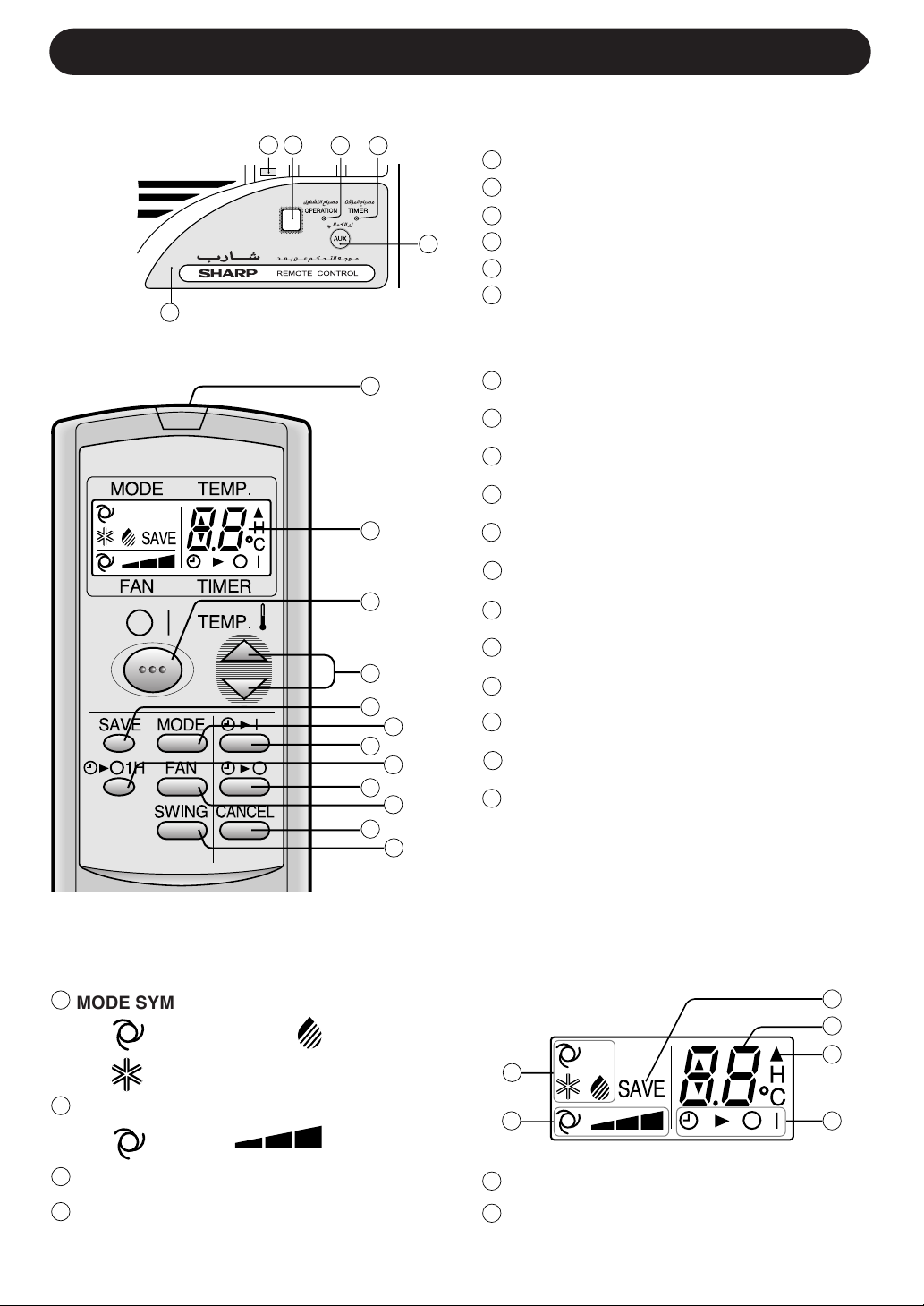
CONTROLS
UNIT
1
6
2
3
4
5
1
Control panel
2
Reciever Window
Operation Lamp (Red)
3
Timer Lamp (Yellow)
4
AUX. Button
5
6
Ventilation lever
REMOTE CONTROL
FAN TIMER
1
2
3
4
5
7
9
11
6
8
10
12
1
TRANSMITTER
2
DISPLAY (Liquid Crystal Display)
3
ON/OFF Button
4
THERMO. (Thermostat) Button
5
SAVE Button
6
MODE Button
7
TIMER ON Button (for setting the timer)
8
ONE-HOUR OFF TIMER Button
9
TIMER OFF Button (for setting the timer)
10
FAN Button
11
TIMER CANCEL Button
12
SWING Button
L.C.D. REMOTE CONTROL DISPLAY
13
MODE SYMBOLS
:AUTO :DRY
:COOL
14
FAN SPEED SYMBOLS
:AUTO :Manual setting
15
SAVE SYMBOL
16
TEMPERATURE AND TIMER COUNT
DOWN INDICATOR
13
14
17
TRANSMITTING SYMBOL
18
TIMER ON/TIMER OFF INDICATOR
Indicates when timer on or timer off is set.
4
15
16
17
18
Page 5
USING THE REMOTE CONTROL
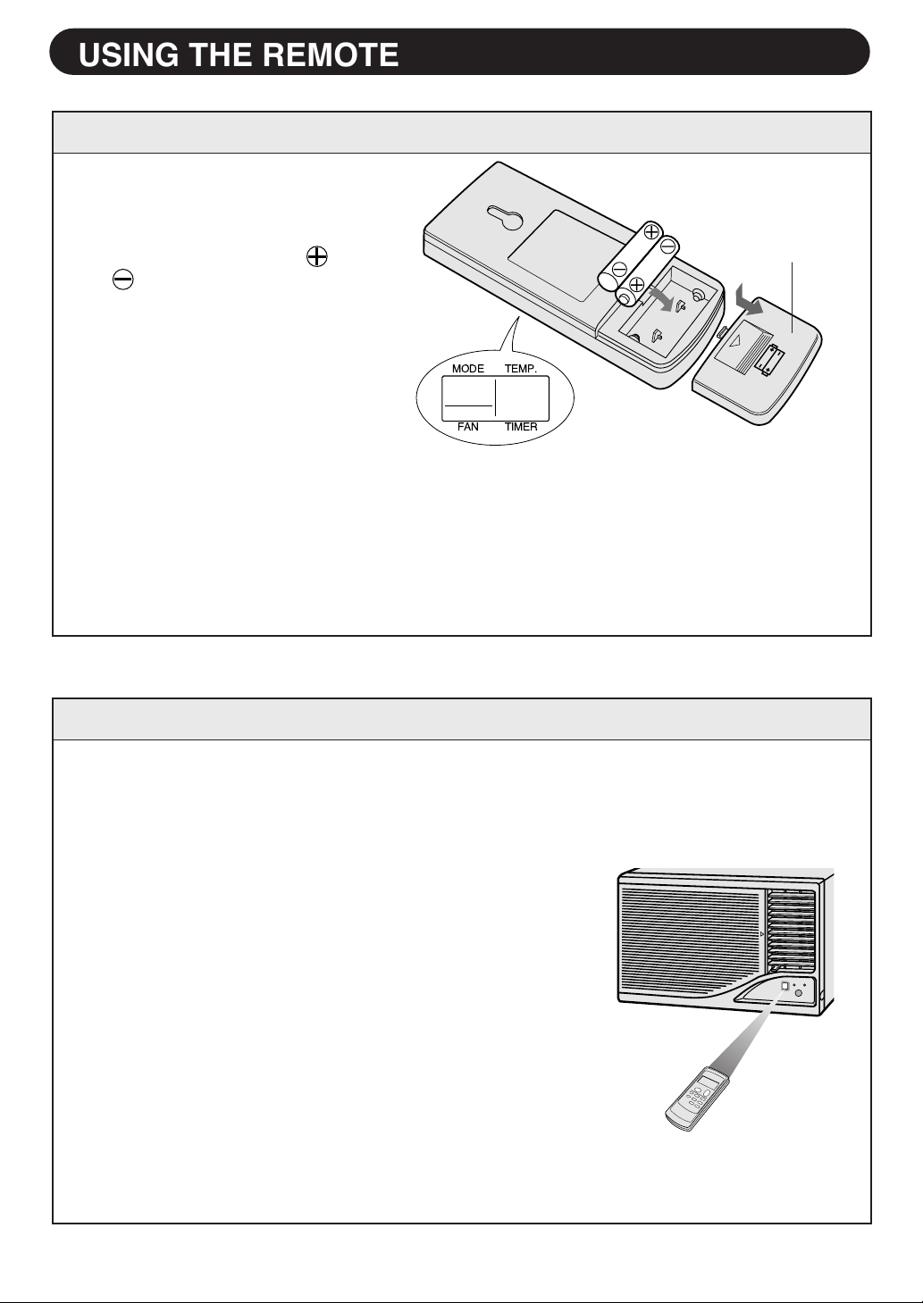
INSTALLING BATTERIES
Remove the battery cover at the
1
back of the remote control.
Insert batteries in the compart-
2
ment, making sure the and
polarities are correctly
aligned.
• Lines will be indicated on the
display when batteries are
properly installed.
Reinstall the battery cover.
3
NOTES:
• The battery life is approximately one year with normal use.
• When you replace the batteries, always use two new ones of the same type.
• If the remote control does not operate normally after replacing the batteries, take out
the batteries and replace them again after 30 seconds.
• If you will not be using the unit for a long time, remove the batteries from the remote
control.
Use two size-AAA (R03) batteries.
Battery cover
MODE TEMP.
FAN TIMER
HOW TO USE THE REMOTE CONTROL
Point the remote control towards the unit’s receiver window and press the desired
button. A beep sound will be emitted when the unit receives the signal
• Make sure no objects, such as curtains, are between
the remote control and the unit.
• The remote control operates from up to 7 meters
away.
• Do not expose the receiver window to strong, direct
sunlight, which can adversely affect its operation. In
such case, close the curtains to block the sunlight.
• Use of a fluorescent lamp with a quick starter in the
same room might interfere with transmission of the
signal.
• The unit might be affected by signals emitted from the
remote control of a television, VCR or other equipment used in the same room.
• Do not leave the remote control in direct sunlight or
near a heater. Also, protect the unit and remote control from moisture and shock which can discolour or
damage them.
.
5
Page 6
BASIC OPERATION
MODE
FAN TIMER
SAVE MODE
FAN1H
SWING
TEMP.
TEMP.
CANCEL
2
5
3
1
4
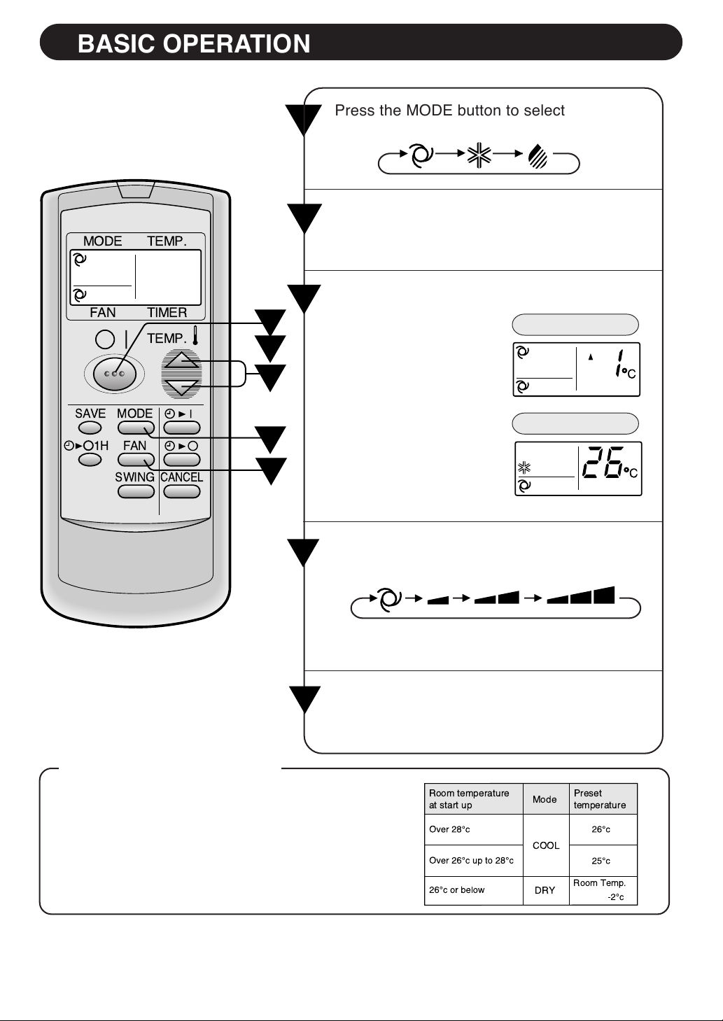
Press the MODE button to select the opera-
1
tion mode.
Press the ON/OFF button to start operation.
2
•
The red OPERATION lamp on the unit will light
up.
Press the THERMO. button to set the de-
3
sired temperature.
• In the AUTO and DRY
mode, the temperature
can be changed in 1°C
increments within the
range of 2°C higher to
2°C lower from the
temperature automatically determined by the
air conditioner.
AUTO COOL DRY
AUTO/DRY MODE
COOL MODE
• In the COOL mode, the
temperature can be set
within the range of 18
°C to 32 °C.
Press the FAN button to set the desired fan
4
speed.
AUTO SOFT LOW HIGH
• In the DRY mode, the fan speed is preset to
AUTO and cannot be changed.
To turn off the unit, press the ON/OFF button
5
again.
The red OPERATION lamp on the unit will turn off.
•
TIPS ABOUT AUTO MODE
In the AUTO MODE, the temperature setting
and mode are automatically selected depending on the room temperature when the unit is
turned on.
Room temperature
at start up
NOTE:
When the room temperature drops during cooling or dry operation, the operation may turn to
fan mode or the operation may stop automatically.
Mode
COOL
DRY
Preset
temperature
Room Temp.
6
Page 7

AIR FLOW AND VENTILATION
LEFT/RIGHT AIR FLOW ADJUSTMENT
Adjust the louvers to change the direction of air
flow. Press the SWING button on the remote
control, and the Left/Right air flow adjustment louvers
will swing continuously. Press the button again to
stop. You can adjust the air flow to your desired
direction.
Never attempt to move the Left/Right air flow
adjustment louvers manually, or manually force the
louver movement to stop during swing operation.
UP/DOWN AIR FLOW ADJUSTMENT
Airflow direction can be adjusted by moving the
airflow adjustment louvers upward or downward.
To avoid condensation on the louvers, please do
not adjust these louvers to extremely downward
position during COOL and DRY modes.
Left/Right air flow adjustment louvers
(Automatic)
SWING
Up/Down air flow
adjustment louvers
VENTILATION LEVER
If air in your room is stale, set the VENTILATION
lever to the RIGHT (OPEN) position. This will
remove stale air from the room. The VENTILATION
lever should normally be kept in the LEFT (CLOSED)
position during cooling operation for maximum
cooling effect.
7
Page 8

TIMER OPERATION
TIMER OFF
The unit will turn off automatically according to your setting.
Timer duration can be set from minimum 0.5 hours (30 minutes) to maximum 12
hours.
Up to 9.5 hours, you can set by 0.5 hours (30 minutes) increments and from 10 to 12
hours, by 1 hour increment.
Press the TIMER OFF ( ) button and set
1
MODE
TEMP.
time as desired.
• The time setting will change as you to press
the button as follows,
FAN TIMER
TEMP.
SAVE MODE
FAN1H
SWING
CANCEL
1
Example : When you wish to
stop the operation
2.5 hours later.
TIPS ABOUT TIMER OFF OPERATION
0.5H 1.0H 1.5H 10H 11H 12H
Hold the button pressed down for fast setting.
• The yellow TIMER lamp on the unit will light
up.
• The unit will generate a beep when it receives the signal.
• The time setting will count down to show
remaining time.
TO CANCEL TIMER
When the TIMER OFF is set, the temperature
setting is automatically adjusted to prevent
the room from becoming excessively cold
while you sleep. (Auto Sleep function)
COOL/DRY MODE:
• One hour after the timer operation begins,
the temperature setting rises 1°C higher
than the original thermostat setting.
Press the CANCEL button.
• The yellow
T I M E R
lamp on
the unit will
SAVE MODE
FAN1H
SWING
turn off.
TO CHANGE TIMER SETTING
Press the TIMER button which you wish to
change, (TIMER OFF or TIMER ON) and
change the time setting.
8
CANCEL
Page 9

TIMER ON
The unit will turn on automatically according to your setting.
Timer duration can be set from minimum 0.5 hours (30 minutes) to maximum 12
hours.
Up to 9.5 hours, you can set by 0.5 hours (30 minutes) increments and from 10 to 12
hours, by 1 hour increment.
Press the TIMER ON ( ) button.
MODE
TEMP.
1
• The time setting will change as you press the
button as follows.
FAN TIMER
TEMP.
SAVE MODE
FAN1H
CANCEL
SWING
Example : When you wish the
room temperature
to be as desired
6.5 hours later.
1
0.5H 1.0H 1.5H 10H 11H 12H
Hold the button pressed down for fast setting.
• The yellow TIMER lamp on the unit will light up.
• The unit will generate a beep when it receives
the signal.
• The time setting will count down to show remaining time.
Select the mode, temperature and fan speed setting as desired.
• When the temperature is set with the TIMER
ON, the temperature will show in the display for
5 seconds and then return to the time display.
• If you do not change the setting, the unit will
operate with the latest setting.
• The unit will turn on prior to the set time to allow
the room to reach the desired temperature by
the programmed time. (Awaking function)
NOTES FOR TIMER SETTING AND OPERATION
• The latest time setting will be memorized and will appear on the remote control display
the next time you set the TIMER OFF or TIMER ON.
• TIMER OFF and TIMER ON can not be set together.
The latest set TIMER will be active.
• When ONE-HOUR OFF TIMER is set, TIMER OFF and TIMER ON will not be available.
• When ONE-HOUR OFF TIMER is set during TIMER OFF or TIMER ON duration, the
TIMER ON or TIMER OFF will be cancelled.
9
Page 10

SAVE OPERATION
With the SAVE operation, the temperature setting rises 1°C higher than the original thermostat setting. It offers you efficient and economical operation when used
during seasons and hours with low outdoor temperature, such as night time.
Press the SAVE button during operation.
1
• The remote control displays “SAVE”.
MODE
FAN TIMER
TEMP.
TEMP.
TO CANCEL
Press the SAVE button again.
• SAVE operation will also be cancelled when the
mode is changed, or when the unit is turned off.
SAVE MODE
FAN1H
SWING
1
CANCEL
NOTE:
• SAVE operation cannot be set during DRY operation.
ONE-HOUR OFF TIMER
When the ONE-HOUR OFF TIMER is set, the unit will stop operating after one hour.
Press the ONE-HOUR OFF TIMER button.
1
• The remote control displays " ".
• The unit will stop operating after one hour.
MODE
FAN TIMER
TEMP.
TEMP.
TO CANCEL
Press the CANCEL button.
Or, turn the unit off by pressing the ON/OFF button.
• The red OPERATION lamp on the unit will turn off.
SAVE MODE
FAN1H
SWING
CANCEL
NOTES:
• The ONE-HOUR OFF TIMER operation has priority over
1
TIMER ON and TIMER OFF operations.
• When the ONE-HOUR OFF TIMER is set while the unit
is not operating, the unit will operate for an hour with the
formerly set condition.
• If you wish to operate the unit for another hour before
the ONE-HOUR OFF-TIMER activates, press the ONEHOUR OFF-TIMER button again during operation.
10
Page 11

AUXILIARY MODE
Use this mode when the remote control is not available.
TO TURN ON
Press the AUX. button on the unit's control
panel.
• The red OPERATION lamp on the unit will
light up and the unit will start operating in the
AUTO mode.
• The fan speed and temperature setting are
set to AUTO.
• Left/Right air flow adjustment louvers will
swing continuously.
TO TURN OFF
Press the AUX. button on the control panel
)7:
again.
• The red OPERATION lamp on the unit will go
out.
NOTE:
If the AUX. button is pressed during normal
operation, the unit will turn off.
11
Page 12

MAINTENANCE
Be sure to disconnect the power cord from the wall outlet or turn off the circuit breaker
before performing any maintenance.
CLEANING THE FILTER
If the filter is clogged with dust, the amount of air flow will be reduced, resulting in poor
cooling performance. The filter should be cleaned every10 days. At the beginning of
every cooling season or if the air conditioner has not been used for a long period, clean
the filter before starting to operate the unit.
REMOVE THE FILTER
1.
Open the grille by gently pulling the arrow
marked portion. Then lift and unhook the bottom of the air filter and remove it.
CAUTION:
Do not open the grille extremely wide, or provide
stress to the opened grille. The grille may come
off, or the grille shaft may get damaged. If the grille
should come off, replace it by following instructions
given in page 16 "CAUTION".
Grille
Air filter
CLEAN THE FILTER
2.
To remove dust from the filter, use a vacuum
cleaner or wash it with clean water.
If the filter is very dirty, wash it with detergent
and rinse carefully with clean water. Dry the
filter with a soft cloth. Do not expose the filter
to heat or dry it under direct sunlight.
3.
RE-INSTALL THE FILTER
Fit the top hooks, and then hook the bottom of
the air filter. Close the grille firmly. Never
operate the unit without installing the filter or
with the grille open. It may result in serious
damage to the unit.
2
1
CLEANING OF THE FRONT PANEL, GRILLE, CABINET AND THE REMOTE CONTROL
To clean the front panel, grille and cabinet, wipe with a soft, dry cloth or with a cloth
moistened with a mild soap. Rinse carefully by wiping with a damp cloth and dry
completely.
Avoid splashing the unit with water. Excessive water will affect electrical insulation and
fire may be resulted during operation.
Never use erosive chemicals or abrasive cleaners on any part of the unit. To avoid
damaging the unit, do not use hot water of over 50°C when cleaning. To clean the
remote control, wipe with a soft
dry cloth.
NOTE:
OILING OF THE COMPRESSOR AND FAN MOTOR IS UNNECESSARY
The compressor is permanently lubricated and is hermetically sealed. The fan motor is lifetime
sealed and does not require oiling.
12
Page 13

BEFORE CALLING FOR SERVlCE
IF YOUR AIR CONDITIONER DOES NOT OPERATE PROPERLY, PLEASE CHECK THE
FOLLOWING ITEMS BEFORE CALLING FOR SERVICE.
AIR CONDITIONER DOES NOT OPERATE AT ALL
• Is the power cord loosened or disconnected?
• Is the fuse blown or has the circuit breaker been tripped?
• Did you restart the unit within 3 minutes after power failure? If the power was off for less than 3 minutes,
and you restart the air conditioner within 3 minutes, a protective device may cause the air conditioner
to shut off, preventing cooling operation for about 5 minutes.
AIR CONDITIONER DOES NOT COOL PROPERLY
• Is the filter covered with heavy dirt?
Clean the filter and replace it.
• Is the temperature setting OK?
If your room is too warm, adjust the temperature setting to a lower level.
If your room is too cool, adjust the temperature setting to a higher level.
• Is the VENTILATION lever set in the RIGHT (OPEN) position?
The lever should be set in the LEFT (CLOSED) position during cooling operation.
• Are the windows exposed to direct sunlight?
Close curtains or blinds to minimize the heat in the room.
• Are the windows or doors open?
Close all windows and doors for maximum cooling effect.
THE UNIT FAILS TO RECEIVE THE REMOTE CONTROL SIGNAL
• Check whether the remote control batteries have become old and weak.
• Try to send the signal again with the remote control pointed properly towards the unit’s receiver
window.
• Check whether the remote control batteries are installed with the polarities properly aligned.
LEFT / RIGHT AIR FLOW ADJUSTMENT LOUVERS DO NOT SWING
• Is the crank shaft fit properly into the louver link?
Remove the front panel, and replace it again. Make sure to slide the crank shaft into the
opening of the louver link at the back of the front panel. (See page 18, step5-(3))
TIMER DOES NOT WORK PROPERLY
• If power failure occurs while the ON or OFF TIMER is set, the TIMER setting memory will
be cancelled and will not be resumed even after power is resumed. You have to reset
them.
FOLLOWINGS ARE NORMAL CONDITIONS OF THIS AIR CONDITIONER
SOUNDS
• The sound of the compressor may seem rather loud for 2 to 3 minutes when the unit is turned
on. This is the sound of the compressor's start-up and is normal for this unit.
• A soft swishing noise can be heard immediately after the unit is turned on or off, and also during
operation. This is the sound of the refrigerant flowing inside the unit.
ODORS
• Carpet and furniture odors may enter the unit and be sent out from the unit.
REPLACING THE GRILLE
• In case the grille comes off, it can be replaced by following the instructions given in page
16 "CAUTION".
13
Page 14

INSTALLATION INSTRUCTIONS
PART NAMES AND DIMENSIONS
1
Front panel
2
,
*
-
+
)
Grille
3
Air filter (behind the grille)
4
Up/Down air flow adjustment louvers
5
Left/Right air flow adjustment louvers
6
Cabinet
7
Ventilation lever
8
Control panel
9
Stopper screws
(on left and right side)
10
Power cord
11
Remote control
DIMENSIONS
A (mm)
B (mm)
C (mm)
D (mm)
E (mm)
We reserve the right to change the materials and specifications without notice.
560
375
600 (center 610)
255
30 (center 40)
ITEMS PACKED WITH THIS UNIT
Accessories
GOLD SCREW (2.5cm/1")
1
2
GOLD SCREW (1.2cm/0.5")
3
GASKET
DRAIN TRAY
4
5
REMOTE CONTROL
6
BATTERY
Q'ty
9
2
1
1
1
2
1
2
4
5
3
6
The long GOLD SCREW ( ) is used to secure the cabinet to the mounting frame.
The short GOLD SCREW ( ) is used to secure the drain tray to the cabinet.
The DRAIN TRAY ( ) is attached to the cabinet, in case drainage is necessary in high humidity
district.See page 16 for detail installation instructions.
4
1
2
14
Page 15

LOCATION
The appliance shall be installed in accordance with national wiring regulations. Improper
connection may cause the power cord, and the electrical outlet to overheat and fire.
Install the air conditioner to the opening dimensions shown below.
Never install the unit where any of the air inlet is blocked.
The air conditioner should be installed with a strong external support to minimize noise and
vibration, and for the purpose of safe installation, repair, replacement and secure positioning.
Avoid installing the air conditioner where it is exposed to direct sunlight.
More than 40cm(16")
More than 20cm(8")
Air inlet
Air outlet
Air inlet
More than 20cm(8")
Air inlet
Air outlet
Air inlet
POWER CABLING
GROUNDING
WARNING: THIS APPLIANCE MUST BE GROUNDED.
Fit a disconnect switch, having a contact separation of at
least 3mm in all poles, to the electricity power line.
Connect the brown wire of the power supply cord to the live
terminal, and the grounding wire (green and yellow) to the
grounding terminal of the electrical outlet. The remaining
wire should be connected to the neutral terminal of the
electrical outlet.
More than 40cm
(16")
Grounding wire
(green&yellow)
Live
(brown)
About 1cm
(3/8")
Neutral
(blue)
FUSE
For safe, trouble free operation, connect the power cord
of the unit to a properly rated independent circuit with a
time delay fuse or a circuit breaker. See chart for proper
amp ratings for each model.
AF-W12CME
15 amp.
15
Maximum Permissible
System Impedance
0.19 ( AF-W12CME)
Page 16

INSTALLATION
INSTALLATION
WARNING: Turn off and disconnect the unit before working.
1
Open the grille (Fig.1) by gently
(1)
pulling the arrow marked portion.
Remove the air filter (Fig.2) from
the front panel.
Unscrew the screw fixing the front
panel to the chassis. (Fig.2)
Keep the screw as it will be used
later.
CAUTION:
Do not open the grille extremely wide, or provide
stress to the opened grille. The grille may come
off, or the grille shaft may get damaged. If the
grille should come off, it can be replaced. Fit one
of the grille shaft into the matching hole on the
front panel, curve the grille slightly and fit in the
other grille shaft.
Grille
Air filter
2
Grille shaft
1
Fig.1
Front panel
Fig.2
Hole
Front
panel
2
(2)
Close the grille firmly, and remove
the front panel by pulling the front
panel at the lower corners towards
you for about 3 cm (1" ). Then lift it
up and pull it towards you. (Fig.3)
Unscrew the 3 stopper screws of
(1)
the cabinet (Fig.4). Keep the front
screw and the angle as they will be
used later in step 5.
Slide the chassis out from the cabi-
(2)
net by pulling on the hand hold
located at the bottom center of the
chassis. (Fig.4)
16
Cabinet
Angle
2
Fig.3
1
Front panel
Chassis
Fig.4
Page 17

Attach the provided drain tray to the
cabinet in case drainage becomes nec-
3
essary. Use the 2 short gold screws
(1.2cm/0.5") to fix it. (Fig.5)
Raised portion
Drain tray can be attached in three
directions according to the installation
location of the air conditioner unit.
Attach drain tray in direction that its brim
will not hit upon the raised of cabinet
edge.
Fig.5-1
When drainage is necessary
water drainage is necessary in high
If
humidity district, remove the rubber cap
on the bottom of the chassis. Remove
the rubber cap from the bottom with a
plier. (Fig.6)
A hose of an appropriate length have to
be attached to the drain tray's drain
outlet. (Fig.7)
Fig.5-2
Fig.5
Drain tray
Cabinet
Fig.5-3
Rubber cap
Fig.6
Chassis
4
(1)
Install the cabinet into the installation
opening.(Fig.8)
(2)
Secure the cabinet to the mounting
frame using the 9 long gold screws.
(2.5cm/1"). (Fig.8)
17
Cabinet
Gasket
Cabinet
Drain tray
Fig.7
Fig.8
Page 18

INSTALLATION
5
WARNING:
At this step, make sure the cabinet is
inclined approximately 1cm (3/8") to
the back (Fig.9).
If the cabinet is not properly inclined,
the water collected in the bottom tray
during operation will not drain properly
and may flow into the room where the
air conditioner is installed.
(3)
Cut the gasket to an appropriate
length and stuff it into the gap
around the mounting frame and
the unit to seal outside air. (Fig.8)
(1)
Slide the chassis back into the
cabinet. (Fig. 10)
(2)
Secure the chassis to the cabinet
using the screw and angle removed
in step 2. Push the angle into the
gap between the chassis and the
cabinet. Hook the angle to the slit
of the cabinet, next screw it on to
the chassis. (Fig. 11)
mounting
frame
Fig.10
cabinet
incline backwards about 1cm
(3/8")
Scratching screw for
grounding.
Fig.9
Serration
Angle
Chassis
Fig.11
SlitCabinet
(3)
Replace the front panel. (Fig.12)
Slide the crank shaft into the opening of the louver link at the back of
the front panel. (Fig.13)
(4)
Open the grille and secure the front
panel with the screw removed in
step 1 (Fig.14). Replace the air
filter and close the grille firmly.
Front panel
Grille
18
Fig.12
Front panel
Crank shaft
Front panel
back view
Louver link
Fig.13
Fig.14
Page 19

19
Page 20

SHARP CORPORATION
20
Printed in Egypt
TINS-A780JBRZ 04B- 1
 Loading...