

Page 1
AY-X36RU
AE-X36RU
1
PRODUCT SPECIFICATION
----------------------------- 2
[1] SPECIFICATION
---------------------------------------- 2
[2] EXTERNAL DIMENSION
----------------------------- 3
ELECTRIC CIRCUIT
----------------------------------------- 4
[1] WIRING DIAGRAM
------------------------------------- 4
[2] CONTROL UNIT PWB WRING
---------------------- 5
FUNCTION AND CONTROL
----------------------------- 6
[1] Remote Control Introduction
------------------------- 6
TROUBLESHOOTING
------------------------------------ 10
[1] Error Code List
----------------------------------------- 10
SERVICE MANUAL
In the interests of user-safety (Required by safety regulations in some countries) the set should be restored to its
original condition and only parts identical to those specied should be used
This document has been published to be used for after sales service only.
The contents are subject to change without notice.
CONTENTS
[2] Troubleshooting for Main Malfunction ----------- 14
[3] Troubleshooting for Normal Malfunction
--------- 29
REFRIGERATION CYCLE
------------------------------ 31
[1] Refrigerant System Diagram
---------------------- 31
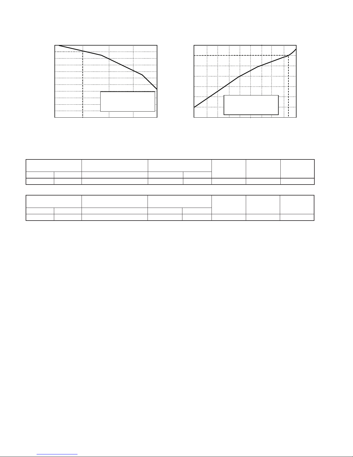
[2] PERFORMANCE CURVES
------------------------ 31
DISASSEMBLY PROCEDURE
------------------------ 33
[1] INDOOR UNIT
----------------------------------------- 33
[2] OUTDOOR UNIT
-------------------------------------- 36
S0402AYX6RCU/c
SPLIT TYPE AIR CONDITIONERS
INDOOR UNIT OUTDOOR UNIT
MODELS
AY-X36RU AE-X36RU
Page 2
2
AY-X36RU
AE-X36RU
PRODUCT SPECIFICATION
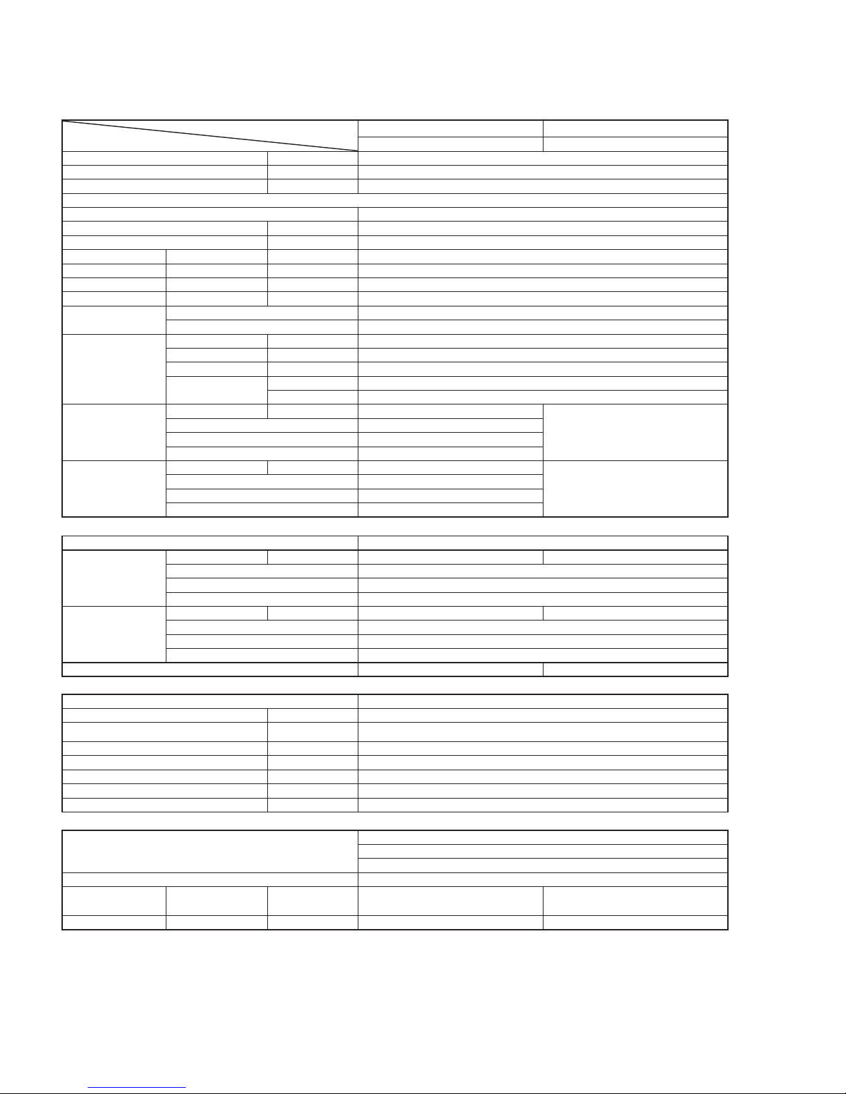
[1] SPECIFICATION
MODEL
ITEMS
INDOOR UNIT OUTDOOR UNIT
AY-X36RU AE-X36RU
Rated cooling capacity (Min. - Max.) Btu/h 33600 ( 7400 - 36000 )
Rated heating capacity (Min. - Max.) Btu/h 34600 ( 15000 - 36000 )
Moisture removal (at cooling) pints/h 7.4
Electrical data
Phase Single
Rated frequency Hz 60
Rated voltage V 208/230
Rated current Cool A 17
(Min.-Max.) Heat A 16.5
Rated input Cool W 4100 ( 450 - 4300 )
(Min.-Max.) Heat W 3800 ( 560 - 4300 )
Compressor
Type Rotary
Model TNB306FPGMC
Refrigerant system
Evaporator Aluminum Fin-copper tube type
Condenser Aluminum Fin-copper tube type
Control Expansion valve
Refrigerant
type R410A
oz. ( g ) 91.7 ( 2600 )
Noise level
(at cooling)
Turbo dB(A) 54
65
High 50
Low 44
Soft 38
Noise level
(at heating)
Turbo dB(A) 54
65
High 50
Low 44
Soft 38
Fan system
Drive Direct drive
Air ow quantity
(at cooling)
Turbo CFM(m3/min) 736 ( 20.8 ) 2589(73.3)
High 647 ( 18.3 )
Low 530 ( 15 )
Soft 412 ( 11.7 )
Air ow quantity
(at heating)
Turbo CFM(m3/min) 736 ( 20.8 ) 2589(73.3)
High 647 ( 18.3 )
Low 530 ( 15 )
Soft 412 ( 11.7 )
Fan Cross ow fan Propeller fan
Connections
Refrigerant coupling Flare type
Refrigerant tube size (Gas line ) inch (mm) 5/8 (16)
Refrigerant tube size (Liquid line ) inch (mm) 1/4 ( 6.35 )
Maximum length ft ( m ) 98.4 ( 30 )
Maximum charge-less length ft ( m ) 24.6 ( 7.5 )
Maximum height difference
ft ( m ) 32.8 ( 10 )
Additional charge oz./ft ( g/m ) 0.5 ( 50 )
Drain pipe O.D. inch (mm) 5/8 (16 )
Others
Safety device
Compressor: Thermal protector
Pressure switch
Fuse, Micro computer control
Air llters Polypropylene net (Washable)
Net dimensions
Width / Height /
Depth
inch
(mm)
53-1/7 / 12-5/6 / 10
( 1350 / 326 / 253 )
38-4/7 / 31-1/9 / 16-4/5
( 980 / 790 / 427 )
Net weight lb. (kg) 41.9 ( 19 ) 161 ( 73 )
NOTE: Test conditions are based on AHRI 210/240. ( Refrigerant piping length : 25ft [7.6m] )
* : Voltage is 230V
Page 3
AY-X36RU
AE-X36RU
3
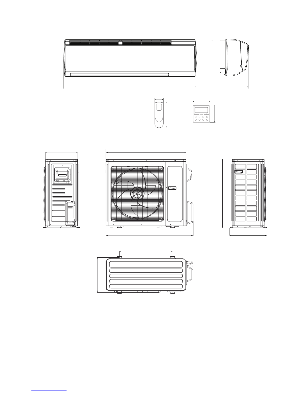
[2] EXTERNAL DIMENSION
Indoor Unit
12.8 (326)
10.0 (253)
3.64 (92.5)
2.2 (56)
3.64 (92.5)
6.7 (170)
53.1 (1350)
Unit: inch (mm)
Thickness: 0.9 (22.5) Thickness: 0.93 (23.5)
Outdoor Unit
14.6 (371)
36 (914.1)
24 (609.6)
15.7 (398.8)
31.1 (790)
38.6 (980)
16.7 (424.2)
Unit: inch (mm)
Page 4
4
AY-X36RU
AE-X36RU
ELECTRIC CIRCUIT
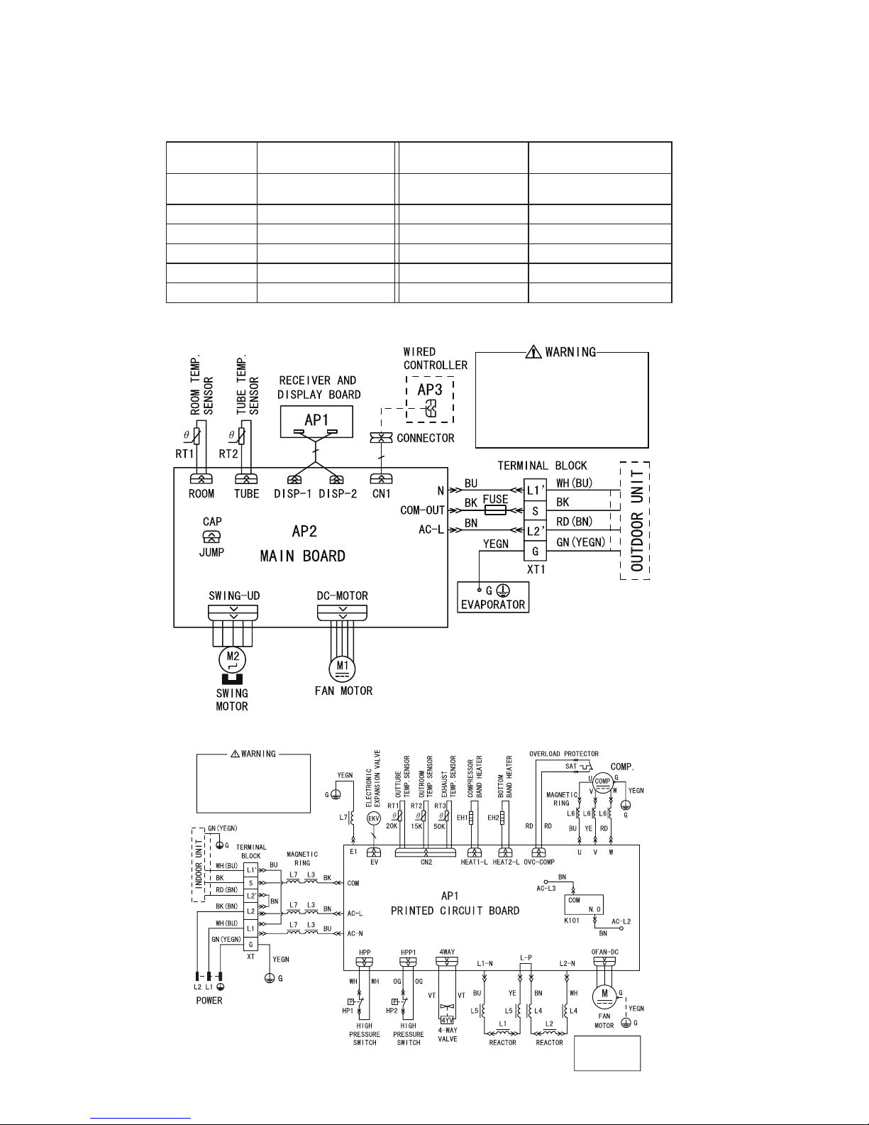
[1] WIRING DIAGRAM
Instruction
Symbol Symbol Color or Name Symbol Symbol Color or Name
WH White BN Brown
YE Yellow BU Blue
RD Red BK Black
YEGN Yellow/Green OG Orange
VT Violet CAP Jumper cap
GN Green COMP Compressor
NOTE: Jumper cap is used to determine fan speed and the swing angle of horizontal lover for this model.
Indoor Unit
Please don't touch any
electronic component or
terminal when the machine
is running,stopping or
has been powered off for
less than 3 minutes to
prevent electric shock !
Outdoor Unit
Please don't touch any
electronic component or
terminal when the machine is
running , stopping or has
been powered off for less
than 30 minutes to prevent
the risk of electric shock !
NOTE:
Motor ground only
applies to the
iron shell motor.
Page 5
AY-X36RU
AE-X36RU
5
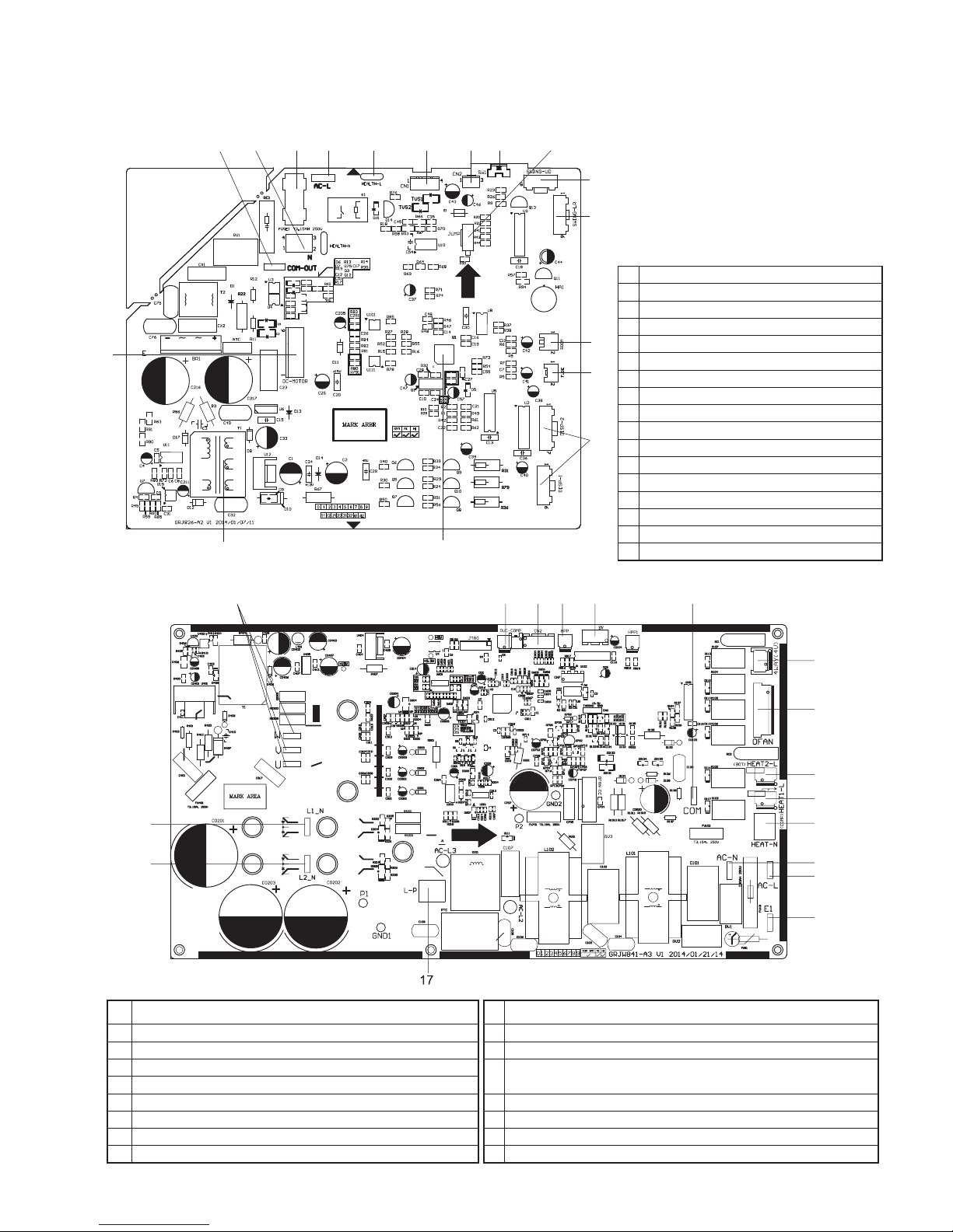
[2] CONTROL UNIT PWB WRING
INDOOR
1
17
16
15
14
13
12
11
10
98
76543
2
1 Interface of fan motor
2 Interface of communication
3 Power supply neutral wire
4 Fuse
5 Power supply live wire
6 Interface of live wire for health function
7 Interface of wired controller
8 Interface of BMS
9 Auto button
10 Jumper cap
11 Interface of up and down swing terminal
12 Interface of left and right swing terminal
13 Ambient temperature sensor interface
14 Indoor tube temperature sensor interface
15 Interface of display
16 Fuse
17 High-frequency terminal
OUTDOOR
3
2
1
4 5 6 7 8
9
10
11
12
13
14
15
16
1 Interface of reactor 1 10 Interface of outdoor fan
2 Interface of reactor 2 11 Electric heater band of chassis HEAT2-L
3 U, V, W three-phase interface of compressor 12 Electric heater band of compressor HEAT1-L
4 Overload protection terminal of compressor OVC-COMP
13
Interface of neutral wire for compressor electric heating and
chassis electric heating
5 Terminal of temperature sensor CN2
6 High pressure protection terminal HPP 14 Interface of live wire
7 Electric expansion valve terminal EV 15 Interface of neutral wire
8 Interface of indoor unit and outdoor unit communication 16 Interface of ground wire
9 Interfacel of 4-way valve 17 Interface of reactor1 and reactor2
Page 6

6
AY-X36RU
AE-X36RU
FUNCTION AND CONTROL
[1] Remote Control Introduction
Buttons on the Remote Control
2
4
7
9
11
12
1 ON/OFF Button
2 MODE Button
3 FAN Button
4 SWING Button
5 TURBO FAN Button
6
/ Button
7 SLEEP Button
8 TEMP Button
9 COMFORT Button
10 DISPLAY Button
11 CLOCK Button
12 TIMER ON/TIMER OFF Button
1
3
5
6
8
10
MODE FAN
TURBO
TEMP
DISPLAY
COMFORT
TIMERONTIMER
OFF
ON/OFF
SWING
SLEEP
CLOCK
Note:
● Once popower is connected, the air conditioner will give out a sound. Operation indictor “ “ is ON (red indicator). After that, the
air conditioner can be operated by using the remote controller.
● Under ON status, pressing the button on the remote controller, the signal icon “ “on the display of remote controller will blink
once and the air conditioner will give out a “de” sound, which means the signal has been sent to the air conditioner.
● Under OFF status, set temperature and clock icon will be displayed on the display of remote controller (If timer on, timer off and
light functions are set, the corresponding icons will be displayed on the display of remote controller at the same time); Under ON
status, the display will show the corresponding set function icons.
1. ON/OFF button
Press this button can turn on or turn off the air conditioner. After turning on the air conditioner, operation indicator " "on indoor
unit’s display is ON (green indicator), and indoor unit will give out a sound.
2. MODE button
Press this button to select your required operation mode.
● When selecting auto mode, air conditioner will operate automatically according to ex-factory setting. Set temperature can’t be
adjusted and will not be displayed as well. Press "FAN" button can adjust fan speed. Press "SWING" button can adjust fan
blowing angle.
● After selecting cool mode, air conditioner will operate under cool mode. Cool indicator " "on indoor unit is ON. Press "▲" or "
▲" button to adjust set temperature. Press "FAN" button to adjust fan speed. Press "SWING" button to adjust fan blowing angle.
● When selecting dry mode, the air conditioner operates at low speed under dry mode. Dry indicator " " on indoor unit is ON.
Under dry mode, fan speed can’t be adjusted. Press "SWING" button to adjust fan blowing angle.
● When selecting fan mode, the air conditioner will only blow fan, no cooling and no heating. All indicators are OFF. Press "FAN"
button to adjust fan speed. Press "SWING" button to adjust fan blowing angle.
Page 7
AY-X36RU
AE-X36RU
7
● When selecting heating mode, the air conditioner operates under heat mode. Heat indicator " " on indoor unit is ON. Press "▲"
or "▼" button to adjust set temperature. Press "FAN" button to adjust fan speed. Press "SWING" button to adjust fan blowing
angle. (Cooling only unit won’t receive heating mode signal. If setting heat mode with remote controller, pressing ON/OFF button
can’t start up the unit).
Note:
● To preven cold air after starting up in heating mode, indoor unit will delay 1~5 minutes to blow air (actual delay time is depend
on indoor ambient temperature).
● Set temperature range from remote controller: 16~30°C(61°F~86°F); Fan speed: auto, low speed, medium speed, high speed.
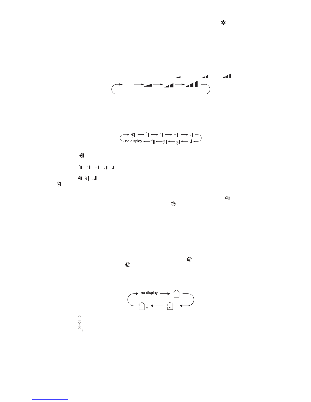
3. FAN button
Pressing this button can set fan speed circularly as: auto (AUTO), low ( ), medium ( ), high ( ).
Auto
Note:
● Under AUTO speed, air conditioner will select proper fan speed automatically.
● Fan speed under dry mode is low speed.
4. SWING button
Press this button can select up&down swing angle. Fan blow angle can be selected circularly as below:
(horizontal louvers stops at current position)
● When selecting " ", air conditioner is blowing fan automatically. Horizontal louver will automatically swing up & down at
maximum angle.
● When selecting "
, , , ,
", air conditioner is blowing fan at xed position. Horizontal louver will stop at the xed
position.
● When selecting "
, ,
" , air conditioner is blowing fan automatically.
● Hold " "button above 2seconds to set your required swing angle. When reaching your required angle, release the button.
5. TURBO FAN button
Under COOL or HEAT mode, press this button to turn to quick COOL or quick HEAT mode. " " icon is displayed on remote
controller. Press this button again to exit TURBO FAN function and " " icon will disappear.
6. ▲/▼ button
● Press "▲" or "▼" button once increase or decrease set temperature 1°C(1~2°F). Holding "▲" or "▼" button, 2seconds later,
set temperature on remote controller will change quickly. On releasing button after setting is nished, temperature indicator on
indoor unit will change accordingly. (Temperature can’t be adjusted under auto mode)
● When setting TIMER ON, TIMER OFF or CLOCK, press "▲" or "▼" button to adjust time. (Refer to CLOCK, TIMER ON, TIMER
OFF buttons) When setting TIMER ON, TIMER OFF or CLOCK, press "▲" or "▼" button to adjust time. (Refer to CLOCK,
TIMER ON, TIMER OFF buttons)
7. SLEEP button
Under COOL or HEAT mode, press this button to start up SLEEP function. " " icon is displayed on remote controller. Press this
button again to cancel SLEEP function and " " icon will disappear.
8. TEMP button
By pressing this button, the indoor set temperature, indoor ambient temperature or outdoor ambient temperature is shown on the
indoor unit’s display. The setting on remote controller is selected circularly as below:
● When selecting " " or no display with remote controller, temperature indicator on indoor unit displays set temperature.
● When selecting " " with remote controller, temperature indicator on indoor unit displays indoor ambient temperature.
● When selecting " " with remote controller, temperature indicator on indoor unit displays outdoor ambient temperature.
Outdoor temperature display is not applicable for this unit. The temperature indicator displays indoor set temperature.
Note:
● It’s defaulted to display set temperature when turning on the unit.There is no display in the remote controller.
● Only for the models whose indoor unit has dual-8 display.
● When the selecting display of indoor or outdoor ambient temperature, indoor temperature indicator displays corresponding
temperature and automatically turn to display set temperature after three or ve seconds.
Page 8

8
AY-X36RU
AE-X36RU
9. COMFORT button
Press this button to start COMFORT function and " " will be displayed on the remote controller. After this function is set, the
remote controller will send the detected ambient temperature to the controller and the unit will automatically adjust the indoor
temperature according to the detected temperature. Press this button again to cancel COMFORT function and "
" will disappear.
● Please put the remote controller near user when this function is set. Do not put the remote controller near the object of high
temperature or low temperature in order to avoid detecting inaccurate ambient temperature.
10. DISPLAY Button
Press this button to turn off the display light on the indoor unit. " " icon on the remote controller disappears. Press this button
again to turn on the display light. " " icon is displayed.
11. CLOCK Button
Press this button to set the clock time. " " icon on the remote controller will blink. Press "▲" or "▼" button within 5seconds to set
the clock time. Each pressing of "▲" or "▼" button, clock time will increase or decrease 1 minute. If hold "▲" or "▼" button,
2seconds later, time will change quickly. Release this button when reaching your required time. Press "CLOCK" button to conrm
the time. " " icon stops blinking.
Note:
● Clock time adopts 24-hour mode.
● The interval between two operation can’t exceeds 5seconds. Otherwise, remote controller will quit setting status. Operation for
TIMER ON/TIMER OFF is the same.
12. TIMER ON / TIMER OFF button
● TIMER ON button
"TIMER ON" button can set the time for timer on. After pressing this button, " " icon disappears and the word "ON" on remote
controller blinks. Press "▲" or "▼"button to adjust TIMER ON setting. After each pressing "▲" or "▼" button, TIMER ON setting
will increase or decrease 1min. Hold "▲" or "▼" button, 2seconds later, the time will change quickly until reaching your required
time. Press "TIMER ON" to conrm it. The word "ON" will stop blinking. " " icon resumes displaying. Cancel TIMER ON: Under
the condition that TIMER ON is started up, press "TIMER ON" button to cancel it.
● TIMER OFF button
"TIMER OFF" button can set the time for timer off. After pressing this button," " icon disappears and the word "OFF" on
remote controller blinks. Press "▲" or "▼" button to adjust TIMER OFF setting. After each pressing "▲" or "▼" button, TIMER
OFF setting will increase or decrease 1min. Hold "▲" or "▼" button, 2seconds later, the time will change quickly until reaching
your required time. Press "TIMER OFF" word "OFF" will stop blinking. "
" icon resumes displaying. Cancel TIMER OFF.
Under the condition that TIMER OFF is started up, press "TIMER OFF" button to cancel it.
Note:
● Under on and off status, you can set TIMER OFF or TIMER ON simultaneously.
● Before setting TIMER ON or TIMER OFF, please adjust the clock time.
● After starting up TIMER ON or TIMER OFF, set the constant circulating valid. After that, air conditioner will be turned on or
turned off according to setting time. ON/OFF button has no effect on setting. If you don’t need this function, please use remote
controller to cancel it.
Function Buttons on the Remote Control
1. Energy-saving function (This function is not explained on the operation manual nor the catalogue)
Under cooling mode, press "TEMP" and "CLOCK" buttons simultaneously to start up or turn off the energy-saving function.
When the energy-saving function is started up, "SE" will be shown on remote controller, and air conditioner will adjust the
set temperature automatically according to ex-factory setting to reach to the best energy-saving effect. Press "TEMP" and
"CLOCK"buttons simultaneously again to exit energy-saving function.
Note:
● Under the energy-saving function, fan speed is defaulted at auto speed and it can’t be adjusted.
● Under the energy-saving function, set temperature can’t be adjusted. Press "TURBO" button and the remote controller won’t
send signal.
● Sleep function and energy-saving function can’t operate at the same time. If energy-saving function has been set under cooling
mode, press sleep button will cancel energy-saving function. If sleep function has been set under cooling mode, start up the
energy-saving function will cancel sleep function.
2. 8°C (46°F) heating function (This function is not explained on the operation manual nor the catalogue)
Under heating mode, press "TEMP" and "CLOCK" buttons simultaneously to start up or turn off the 8°C heating function. When
this function is started up, " " and "8°C" will be shown on the remote controller, and the air conditioner keep the heating status at
8°C. Press "TEMP" and "CLOCK" buttons simultaneously again to exit 8°C heating function.
Note:
● Under the 8°C heating function, fan speed is defaulted at auto speed and it can’t be adjusted.
● Under the 8°C heating function, set temperature can’t be adjusted. Press "TURBO" button and the remote controller won’t send
signal.
● The sleep function and the 8°C heating function can’t operate at the same time. If 8°C heating function has been set under
cooling mode, press sleep button will cancel 8°C heating function. If sleep function has been set under cooling mode, start up
the 8°C heating function will cancel sleep function.
Page 9
AY-X36RU
AE-X36RU
9
● Under °F temperature display, the remote controller will display 46°F heating.
3. Lock function
Press "▲" and "▼" simultaneously to turn on or turn off lock function. When lock function is on, " " icon is displayed on remote
controller. If you operate the remote controller, the " " icon will blink three times without sending signal to the unit.
4. Temperature display switch over function
Under OFF status, press "▲" and "MODE" buttons simultaneously to switch temperature display between °C and °F.
Operation guide
1. Once power is connected, press "ON/OFF" button on remote controller to turn on the air conditioner.
2. Press "MODE" button to select your required mode: AUTO, COOL, DRY, FAN, HEAT.
3. Press "▲" or "▼" button to set your required temperature. (Temperature can’t be adjusted under auto mode).
4. Press "FAN" button to set your required fan speed: auto, low, medium and high speed.5. Press "SWING" button to select fan
blowing angle.
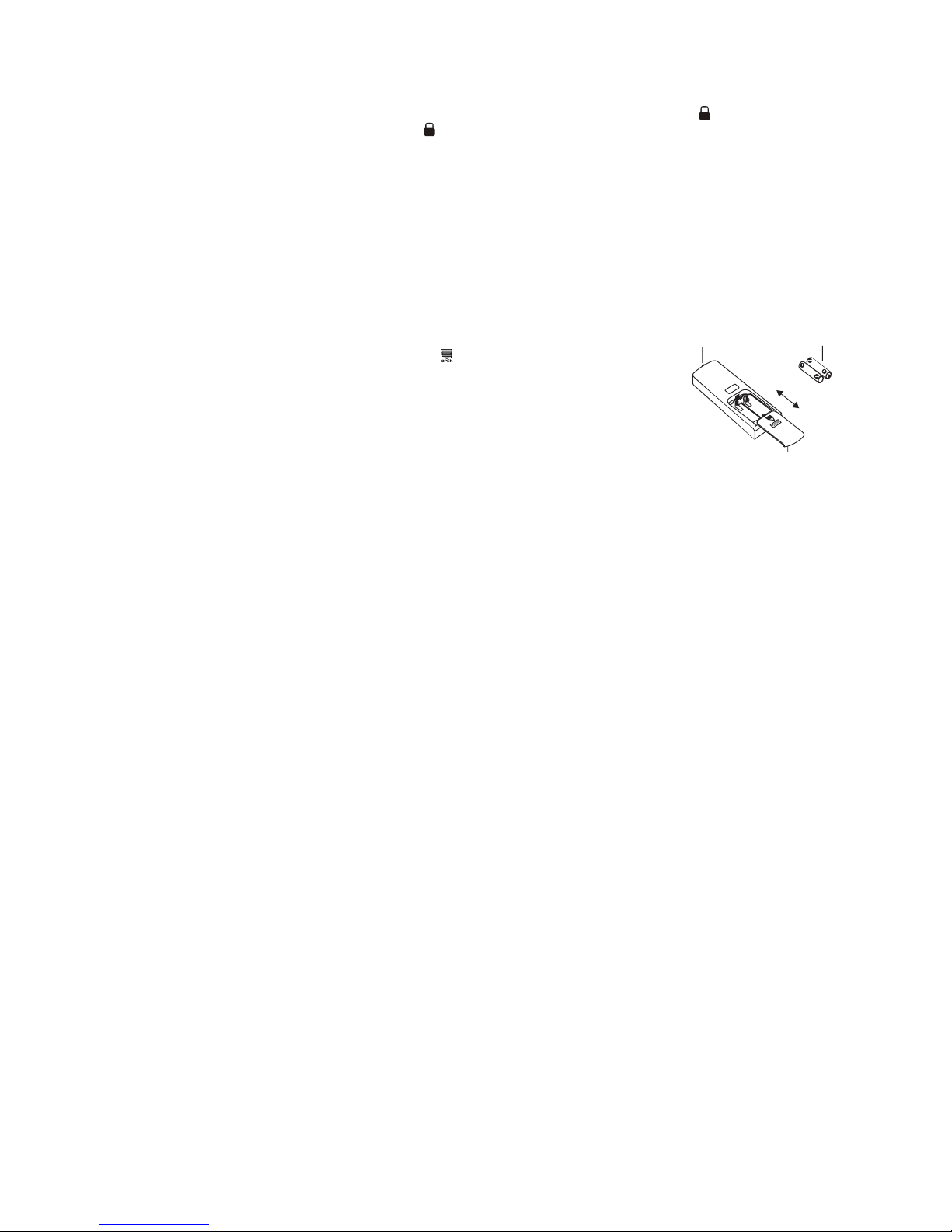
Replacement of batteries in remote controller
1. Press the back side of remote controller marked with " ", as shown in the g, and then
push out the cover of battery box along the arrow direction.
2. Replace two 7# (AAA 1.5V) dry batteries, and make sure the position of "+" polar and
"-" polar are correct.
3. Reinstall the cover of the battery box.
Battery
Cover of battery box
Reinstall
Remove
Signal sender
Note:
● During operation, point the remote control signal sender at the receiving window of the indoor unit.
● The distance between signal sender and receiving window should be no more than 8m, and there should be no obstacles between
them.
● Signal may be interfered easily in the room where there is uorescent lamp or wireless telephone; remote controller should be close
to indoor unit during operation.
● Replace new batteries of the same model when replacement is required.
● When you don’t use remote controller for a long time, please take out the batteries.
● If the display on remote controller is fuzzy or there’s no display, please replace batteries.
Page 10
10
AY-X36RU
AE-X36RU
TROUBLESHOOTING
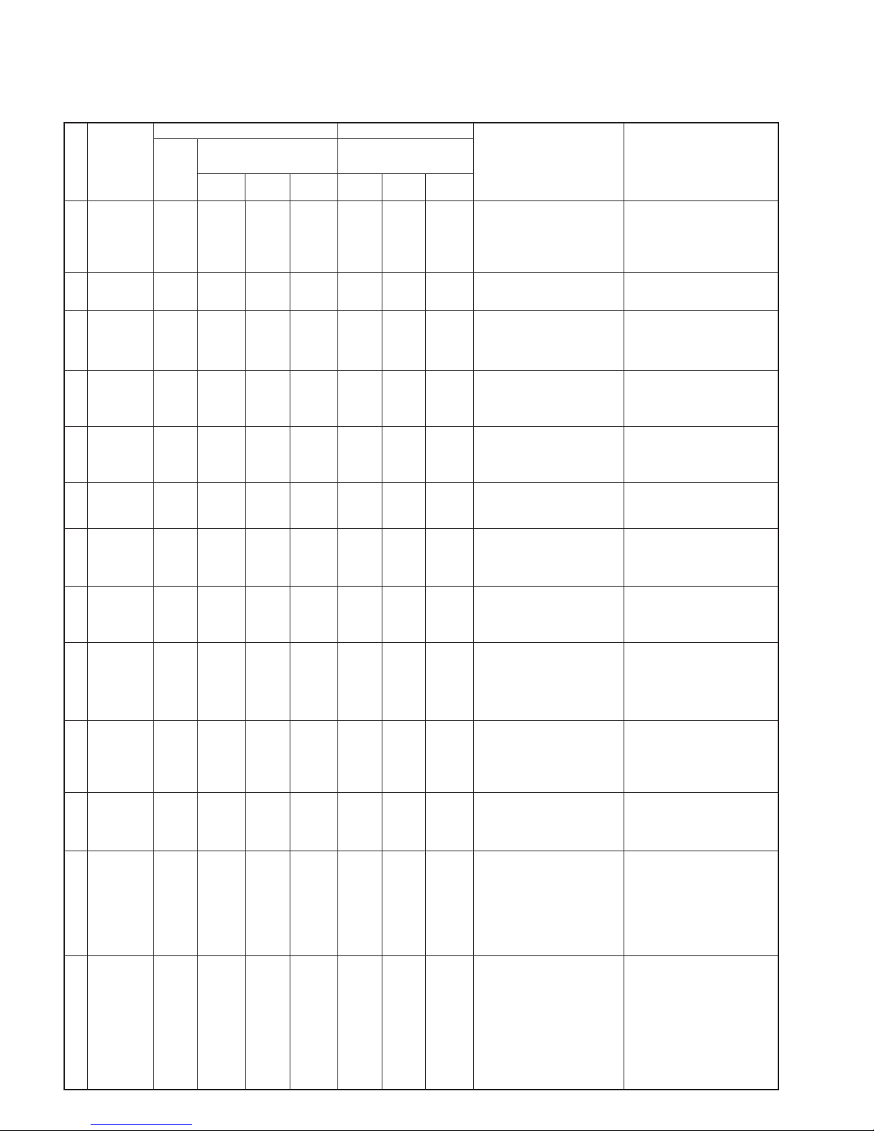
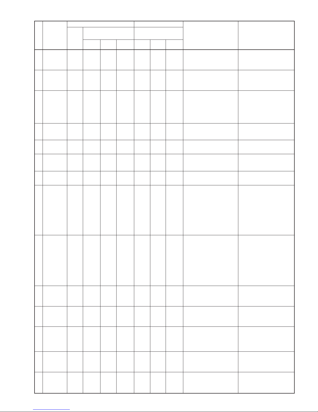
[1] Error Code List
NO.
Malfunction
Name
Display Method of Indoor Unit Display Method of Outdoor Unit
A/C status Possible Causes
Dual 8
Code
Display
Indicator Display (during blink-
ing, ON 0.5s and OFF 0.5s)
Indicator has 3 kinds of display
status and during blinking, ON
0.5s and OFF 0.5s
Operation
Indicator
Cool
Indicator
Heating
Indicator
Yellow
Indicator
Red
Indicator
Green
Indicator
1
High pressure
protection of
system
E1
OFF 3s
and blink
once
During cooling and drying operation, except indoor fan operates, all
loads stop operation. During heating operation, the complete unit
stops.
Possible reasons:
1. Refrigerant was superabundant;
2. Poor heat exchange (including
fifth blockage of heat exchanger
and bad radiating environment );
Ambient temperature is too high.
2
Antifreezing
protection
E2
OFF 3S
and blink
twice
OFF 1S
and blink
3 times
During cooling and drying operation, compressor and outdoor fan
stop while indoor fan operates.
1. Poor air-return in indoor unit;
2. Fan speed is abnormal;
3. Evaporator is dirty.
3
In defect of
refrigerant
F0
OFF 1S
and blink
9 times
The Dual 8 Code Display will show
F0 and the complete unit stops.
1. In defect of refrigerant;
2. Indoor evaporator temperature
sensor works abnormally;
3. The unit has been plugged up
somewhere.
4
High discharge
temperature
protection of
compressor
E4
OFF 3S
and blink
4 times
OFF 1S
and blink
7 times
During cooling and drying operation, compressor and outdoor fan
stop while indoor fan operates.
During heating operation, all loads
stop.
Please refer to the malfunction
analysis (discharge protection, overload).
5
Over current
protection
E5
OFF 3S
and blink
5 times
OFF 1S
and blink
5 times
During cooling and drying operation, compressor and outdoor fan
stop while indoor fan operates.
During heating operation, all loads
stop.
1. Supply voltage is unstable;
2. Supply voltage is too low and
load is too high;
3. Evaporator is dirty.
6
Communication Malfunction
E6
OFF 3S
and blink
6 times
Always
ON
During cooling operation, compressor stops while indoor fan motor
operates. During heating operation,
the complete unit stops.
Refer to the corresponding malfunction analysis.
7
High temperature resistant
protection
E8
OFF 3S
and blink
8 times
OFF 1S
and blink
6 times
During cooling operation: compressor will stop while indoor fan will
operate.
During heating operation, the complete unit stops.
Refer to the malfunction analysis
(overload, high temperature resistant).
8
EEPROM malfunction
EE
OFF 3S
and blink
15 times
OFF 1S
and blink
11 times
During cooling and drying operation, compressor will stop while
indoor fan will operate; During
heating operation, the complete
unit will stop
Replace outdoor control panel AP1
9
Limit/decrease
frequency
due to high
temperature of
module
EU
OFF 3S
and blink
6 times
OFF 3S
and blink
6 times
All loads operate normally, while
operation frequency for compressor is decreased
Discharging after the complete unit
is de-energized for 20mins, check
whether the thermal grease on IPM
Module of outdoor control panel AP1
is sufficient and ahether the radiator
is inserted tightly. If its no use, please
replace control panel AP1
.
10
Malfunction
protection of
jumper cap
C5
OFF 3S
and blink
15 times
Wireless remote receiver and button are effective, but can not dispose the related command
1. No jumper cap insert on main
board.
2. Incorrect insert of jumper cap.
3. Jumper cap damaged.
4. Abnormal detecting circuit of
main board.
11
Gathering
refrigerant
Fo
OFF 3S
and blink
1 times
OFF 3S
and blink
1 times
OFF 1S
and blink
17 times
When the outdoor unit receive signal of Gathering refrigerant
,the system will be forced to run
under cooling mode for gathering
refrigerant
Nominal cooling mode
12
Indoor ambient
temperature
sensor is open/
short circuited
F1
OFF 3S
and blink
once
During cooling and drying operation, indoor unit operates while
other loads will stop; during heating
operation,
the complete unit will stop operation.
1. Loosening or bad contact of
indoor ambient temp. sensor and
main board terminal.
2. Components in main board fell
down leads short circuit.
3. Indoor ambient temp. sensor
damaged.(check with sensor
resistance value chart)
4. Main board damaged.
13
Indoor evaporator temperature sensor
is open/short
circuited
F2
OFF 3S
and blink
twice
AC stops operation once reaches
the setting temperature. Cooling,
drying: internal fan motor stops
operation while other loads stop
operation; heating: AC stop operation
1. Loosening or bad contact of
Indoor evaporator temp. sensor
and main board terminal.
2. Components on the main board
fall down leads short circuit.
3. Indoor evaporator temp. sensor
damaged.(Check temp. sensor
value chart for testing)
4. Main board damaged.
Page 11
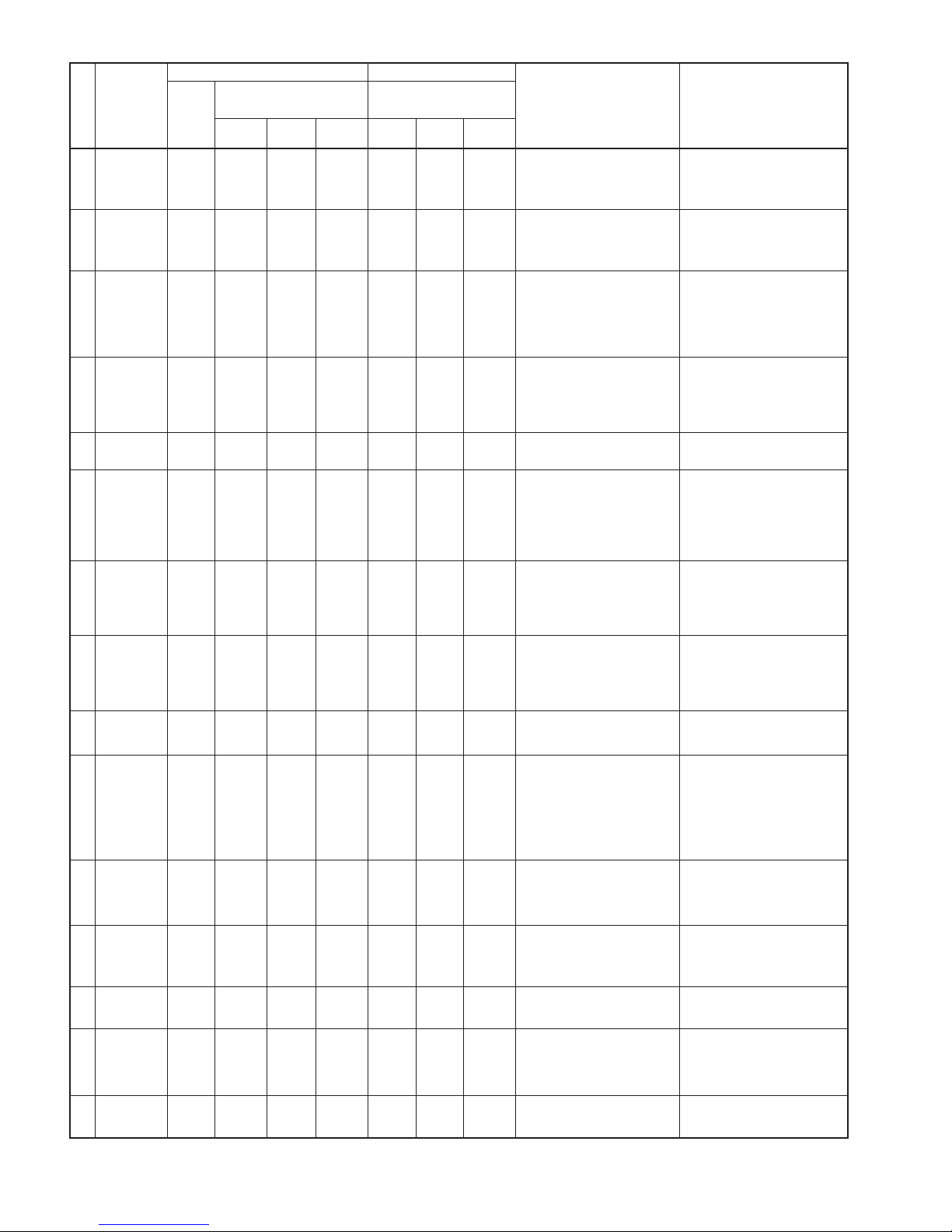
AY-X36RU
AE-X36RU
11
NO.
Malfunction
Name
Display Method of Indoor Unit Display Method of Outdoor Unit
A/C status Possible Causes
Dual 8
Code
Display
Indicator Display (during blink-
ing, ON 0.5s and OFF 0.5s)
Indicator has 3 kinds of display
status and during blinking, ON
0.5s and OFF 0.5s
Operation
Indicator
Cool
Indicator
Heating
Indicator
Yellow
Indicator
Red
Indicator
Green
Indicator
14
Outdoor ambient temperature sensor
is open/short
circuited
F3
OFF 3S
and blink
3 times
OFF 1S
and blink
6 times
During cooling and drying operating, compressor stops while indoor
fan operates; During heating operation, the complete unit will stop
operation
Outdoor temperature sensor hasn’t
been connected well or is damaged.
Please check it by referring to the
resistance table for temperature
sensor)
15
Outdoor
condenser
temperature
sensor is open/
short circuited
F4
OFF 3S
and blink
4 times
OFF 1S
and blink
5 times
During cooling and drying operation, compressor stops while indoor
fan will operate; During heating
operation, the complete unit will
stop operation.
Outdoor temperature sensor has
not been connected well or is damaged. Please check it by referring to
the resistance table for temperature
sensor)
16
Outdoor
discharge
temperature
sensor is open/
short circuited
F5
OFF 3S
and blink
5 times
OFF 1S
and blink
7 times
During cooling and drying operation, compressor will sop after
operating for about 3 mins, while
indoor fan will operate; During
heating operation, the complete
unit will stop after operating for
about 3 mins.
1. Outdoor temperature sensor
has not been connected well or
is damaged. Please check it by
referring to the resistance table
for temperature sensor)
2. The head of temperature sensor
has not been inserted into the
copper tube
17
Limit/ decrease
frequency due
to overload
F6
OFF 3S
and blink
for 6
times
OFF 1S
and blink
3 times
All loads operate normally, while
operation frequency for compressor is decreased
Refer to the malfunction analysis
(overload, high temperature resistant)
18
Decrease frequency due to
overcurrent
F8
OFF 3S
and blink
8 times
OFF 1S
and blink
once
All loads operate normally, while
operation frequency for compressor is decreased
The input supply voltage is too low;
System pressure is too high and
overload
19
Decrease
frequency due
to high air discharge
F9
OFF 3S
and blink
9 times
OFF 1S
and blink
twice
All loads operate normally, while
operation frequency for compressor is decreased
Overload or temperature is too high;
Malfunction of electric expansion
valve (EKV)
20
Limit/ decrease
frequency due
to antifreezing
FH
OFF 3S
and blink
2 times
OFF 3S
and blink
2 times
OFF 1S
and blink
4 times
All loads operate normally, while
operation frequency for compressor is decreased
Poor air-return in indoor unit or fan
speed is too low
21
Voltage for DC
bus-bar is too
high
PH
OFF 3S
and blink
11 times
OFF 1S
and blink
13 times
During cooling and drying operation, compressor will stop while
indoor fan will operate; During
heating operation, the complete
unit will stop operation.
1. Measure the voltage of position L
and N on wiring board (XT), if the
voltage is higher than 265VAC,
turn on the unit after the supply
voltage is increased to the normal range.
2. If the AC input is normal, measure the voltage of electrolytic
capacitor C on control panel
(AP1), if its normal, there is malfunction for the circuit, please
replace the control panel (AP1)
22
Voltage of DC
bus-bar is too
low
PL
OFF 3S
and blink
21 times
OFF 1S
and blink
12 times
During cooling and drying operation, compressor will stop while
indoor fan will operate; During
heating operation, the complete
unit will stop
1. Measure the voltage of position L
and N on wiring board (XT), if the
voltage is higher than 150VAC,
turn on the unit after the supply
voltage is increased to the normal range.
2. If the AC input is normal, measure the voltage of electrolytic
capacitor C on control panel
(AP1), if its normal, there’s malfunction for the circuit, please
replace the control panel (AP1)
23
Compressor
Min frequence
in test state
P0
(during
blinking,
ON 0.25s
and OFF
0.25s)
(during
blinking,
ON 0.25s
and OFF
0.25s)
Showing during min. cooling or min.
heating test
24
Compressor
rated frequence in test
state
P1
(during
blinking,
ON 0.25s
and OFF
0.25s)
(during
blinking,
ON 0.25s
and OFF
0.25s)
Showing during nominal cooling or
nominal heating test
25
Compressor
maximum frequence in test
state
P2
(during
blinking,
ON 0.25s
and OFF
0.25s)
(during
blinking,
ON 0.25s
and OFF
0.25s)
Showing during max. cooling or
max. heating test
26
Compressor
intermediate
frequence in
test state
P3
(during
blinking,
ON 0.25s
and OFF
0.25s)
(during
blinking,
ON 0.25s
and OFF
0.25s)
Showing during middle cooling or
middle heating test
27
Overcurrent
protection of
phase current
for compressor
P5
OFF 3S
and blink
15 times
During cooling and drying operation, compressor will stop while
indoor fan will operate; During
heating operation, the complete
unit will stop operation.
Refer to the malfunction analysis
(IPM protection, loss of synchronism
protection and over current protection of phase current for compressor.
Page 12
12
AY-X36RU
AE-X36RU
NO.
Malfunction
Name
Display Method of Indoor Unit Display Method of Outdoor Unit
A/C status Possible Causes
Dual 8
Code
Display
Indicator Display (during blink-
ing, ON 0.5s and OFF 0.5s)
Indicator has 3 kinds of display
status and during blinking, ON
0.5s and OFF 0.5s
Operation
Indicator
Cool
Indicator
Heating
Indicator
Yellow
Indicator
Red
Indicator
Green
Indicator
28
Charging
malfunction of
capacitor
PU
OFF 3S
and blink
17 times
During cooling and drying operation, compressor will stop while
indoor fan will operate; During
heating operation, the complete
unit will stop
Refer to the part three—charging
malfunction analysis of capacitor
29
Malfunction
of module
temperature
sensor circuit
P7
OFF 3S
and blink
18 times
During cooling and drying operation, compressor will stop while
indoor fan will operate; During
heating operation, the complete
unit will stop
Replace outdoor control panel AP1
30
Module high
temperature
protection
P8
OFF 3S
and blink
19 times
During cooling operation, compressor will stop while indoor fan will
operate;
During heating operation, the complete unit will stop
After the complete unit is de- energized for 20mins, check whether
the thermal grease on IPM Module
of outdoor control panel radiator is
inserted tightly. If its no use, please
replace control panel AP1.
31
Decrease frequency due to
high temperature resistant
during heating
operation
H0
OFF 3S
and blink
10 times
All loads operate normally, while
operation frequency for compressor is decreased
Refer to the malfunction analysis
(overload, high temperature resistant)
32
Static dedusting protection
H2
OFF 3S
and blink
twice
33
Overload
protection for
compressor
H3
OFF 3S
and blink
3 times
OFF 1S
and blink
8 times
During cooling and drying operation, compressor will stop while
indoor fan will operate; During
heating operation, the complete
unit will stop operation.
1. Wiring terminal OVC-COMP is
loosened. In normal state, the
resistance for this terminal should
be less than 1ohm.
2. Refer to the malfunction analysis
(discharge protection, overload)
34
System is
abnormal
H4
OFF 3S
and blink
4 times
OFF 1S
and blink
6 times
During cooling and drying operation, compressor will stop while
indoor fan will operate; During
heating operation, the complete
unit will stop operation.
Refer to the malfunction analysis
(overload, high temperature resistant)
35 IPM protection H5
OFF 3S
and blink
5 times
OFF 1S
and blink
4 times
During cooling and drying operation, compressor will stop while
indoor fan will operate; During
heating operation, the complete
unit will stop operation.
Refer to the malfunction analysis
(IPM protection, loss of synchronism
protection and over current protection of phase current for compressor.
36
Module temperature is too
high
H5
OFF 3S
and blink
5 times
OFF 1S
and blink
10 times
37
Internal motor
(fan motor) do
not operate
H6
OFF 3S
and blink
11 times
Internal fan motor, external fan
motor, compressor and electric
heater stop operation,guide louver
stops at present location.
1. Bad contact of DC motor feedback terminal.
2. Bad contact of DC motor control
end.
3. Fan motor is stalling.
4. Motor malfunction.
5. Malfunction of main board rev
detecting circuit.
38
Desynchronizing of compressor
H7
OFF 3S
and blink
7 times
During cooling and drying operation, compressor will stop while
indoor fan will operate; During
heating operation, the complete
unit will stop operation.
Refer to the malfunction analysis
(IPM protection, loss of synchronism
protection and over current protection of phase current for compressor.
39
PFC
protection
HC
OFF 3S
and blink
6 times
OFF 1S
and blink
14 times
During cooling and drying operation, compressor will stop while
indoor fan will operate; During
heating operation, the complete
unit will stop operation.
Refer to the malfunction analysis
40
Outdoor DC
fan motor malfunction
L3
OFF 3S
and blink
23 times
OFF 1S
and blink
14 times
Outdoor DC fan motor malfunction
lead to compressor stop operation,
DC fan motor malfunction or system
blocked or the connector loosed
41
power protec
-
tion
L9
OFF 3S
and blink
20 times
OFF 1S
and blink
9 times
Compressor stop operation and
Outdoor fan motor will stop 30s latter , 3 minutes latter fan motor and
compressor will restart
To protect the electrical components
when detect high power
42
Indoor unit and
outdoor unit
doesn't match
LP
OFF 3S
and blink
19 times
OFF 1S
and blink
16 times
Compressor and Outdoor fan
motor can’t work
Indoor unit and outdoor unit doesn't
match
Page 13
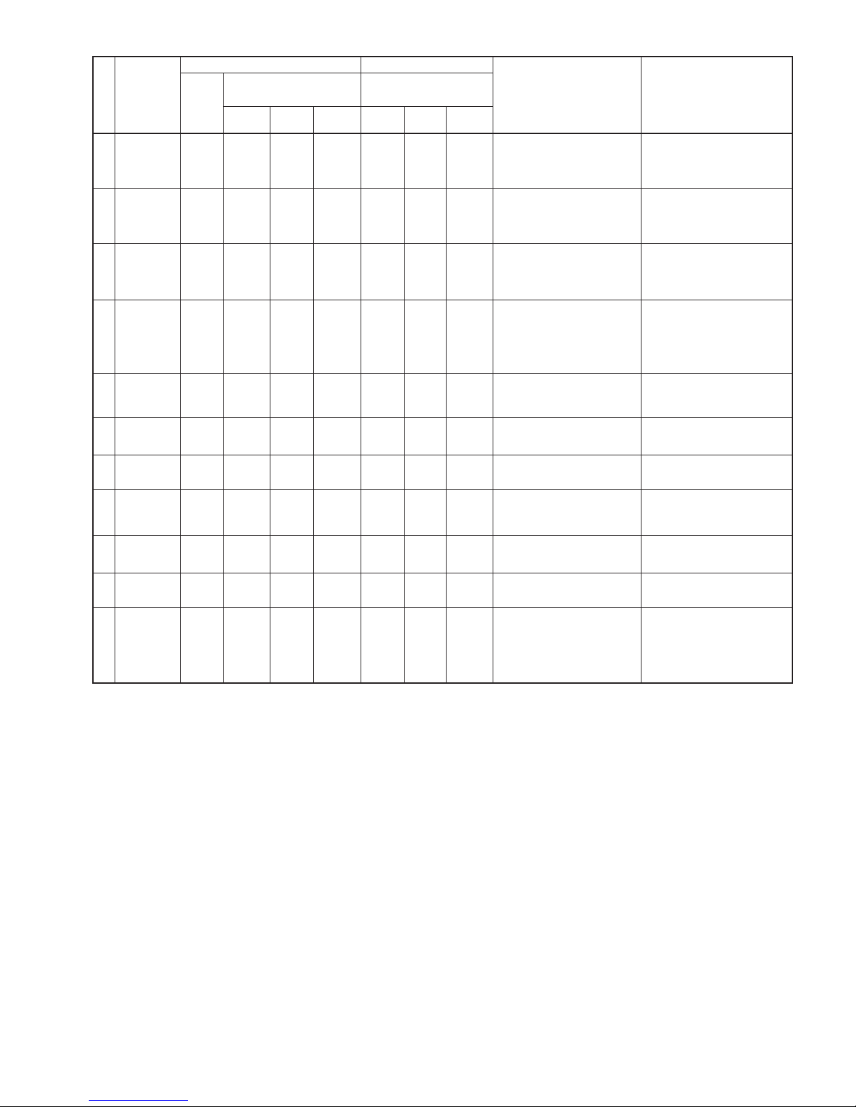
AY-X36RU
AE-X36RU
13
NO.
Malfunction
Name
Display Method of Indoor Unit Display Method of Outdoor Unit
A/C status Possible Causes
Dual 8
Code
Display
Indicator Display (during blink-
ing, ON 0.5s and OFF 0.5s)
Indicator has 3 kinds of display
status and during blinking, ON
0.5s and OFF 0.5s
Operation
Indicator
Cool
Indicator
Heating
Indicator
Yellow
Indicator
Red
Indicator
Green
Indicator
43
Failure startup
LC
OFF 3S
and blink
11 times
During cooling and drying operation, compressor will stop while
indoor fan will operate; During
heating operation, the complete
unit will stop operation.
Refer to the malfunction analysis
45
Malfunction of
voltage dropping for DC
bus-bar
U3
OFF 3S
and blink
20 times
During cooling and drying operation, compressor will stop while
indoor fan will operate; During
heating operation, the complete
unit will stop
Supply voltage is unstable
46
Malfunction of
complete units
current detection
U5
OFF 3S
and blink
13 times
During cooling and drying operation, the compressor will stop while
indoor fan will operate;
During heating operating, the complete unit will stop operation.
There’s circuit malfunction on outdoor units control panel AP1, please
replace the outdoor units control
panel AP1.
47
The four-way
valve is abnormal
U7
OFF 3S
and blink
20 times
If this malfunction occurs during
heating operation, the complete
unit will stop operation.
1. Supply voltage is lower than
AC175V;
2. Wiring terminal 4V is loosened or
broken; 3.4V is damaged, please
replace 4V.
48
Zero- crossing
malfunction of
outdoor unit
U9
OFF 3S
and blink
18 times
During cooling operation, compressor will stop while indoor fan will
operate; during heating,the complete unit will stop operation.
Replace outdoor control panel AP1
49
Frequency limiting (power)
OFF 1S
and blink
13 times
50
Compressor
running
OFF 1S
and blink
once
51
The temperature for turning
on the unit is
reached
OFF 1S
and blink
8 times
52
Frequency limiting (module
temperature)
OFF 1S
and blink
11 times
53
Normal communication
OFF 0.5S
and blink
once
54 Defrosting
OFF 3S
and blink
once (during blinking, ON
10s and
OFF 0.5s)
OFF 1S
and blink
twice
Defrosting will occur in heating
ode. Compressor will operate while
indoor fan will stop operation.
Its the normal state
Page 14

14
AY-X36RU
AE-X36RU
[2] Troubleshooting for Main Malfunction
1.
Malfunction of Temperature Sensor F1, F2
Main detection points:
● Is the wiring terminal between the temperature sensor and the controller loosened or poorly contacted?
● Is there short circuit due to trip-over of the parts?
● Is the temperature sensor broken?
● Is main board broken?
Is the problem fixed?
Is the problem fixed?
Is the problem fixed?
Replace it with the
temperature sensor.
Page 15
AY-X36RU
AE-X36RU
15
2.
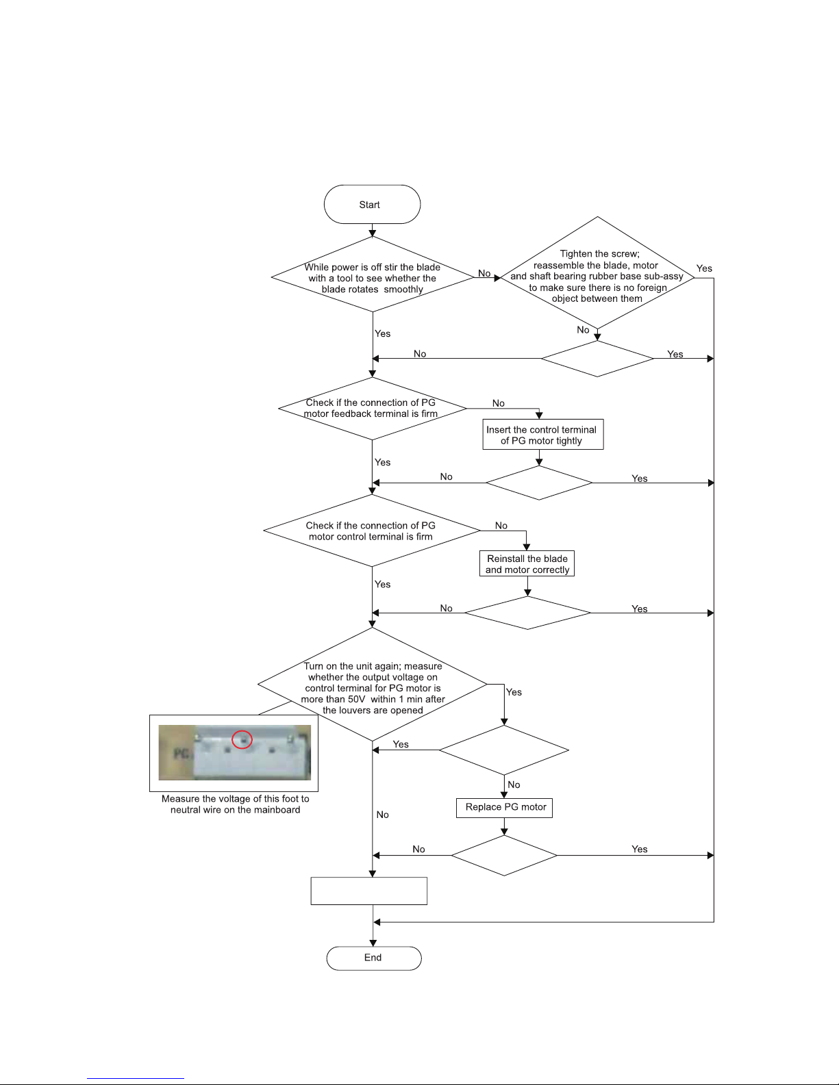
Malfunction of Blocked Protection of IDU Fan Motor H6
Main detection points:
● SmoothlyIs the control terminal of PG motor connected tightly?
● SmoothlyIs the feedback interface of PG motor connected tightly?
● The fan motor can’t operate
● The motor is broken?
● Detectioncircuit of the main board is dened abnormal?
Is the problem
fixed?
Is the problem
fixed?
Is the problem
fixed?
Is the motor started up?
Replace the main board.
Is the problem
fixed?
Page 16
16
AY-X36RU
AE-X36RU
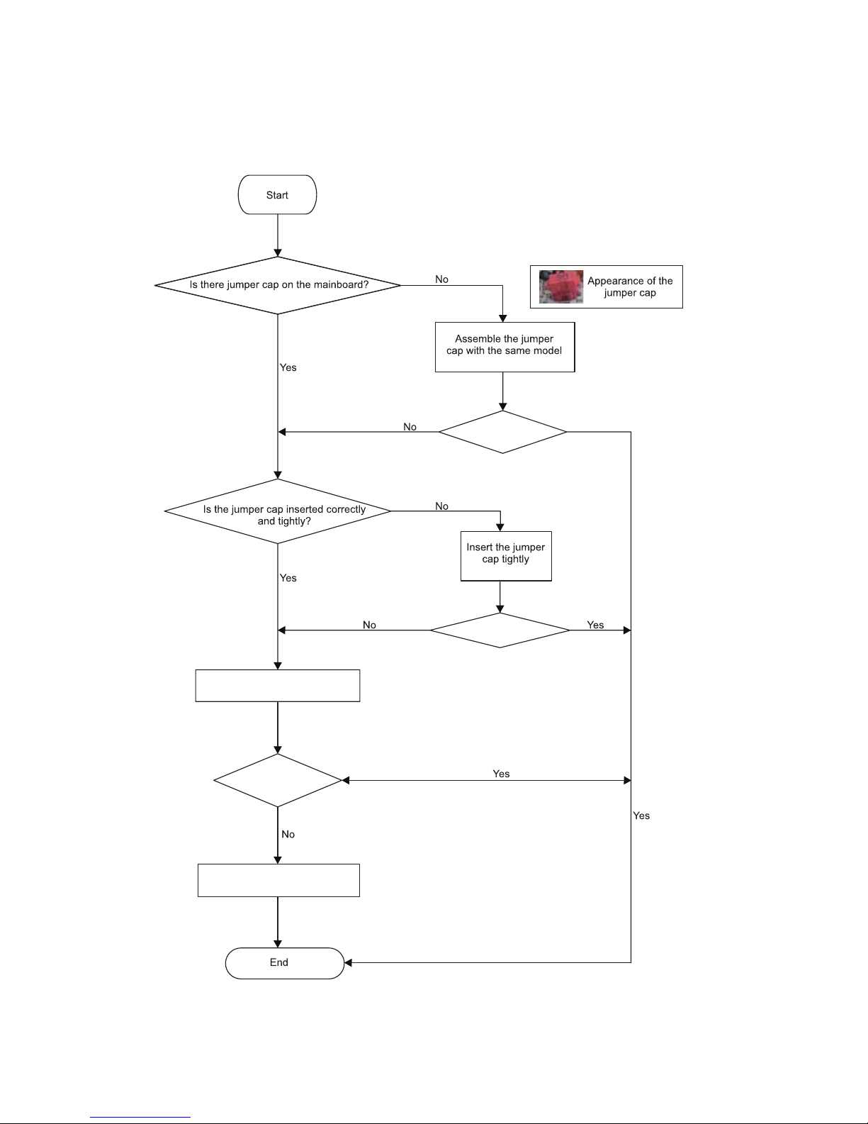
3.
Malfunction of Protection of Jumper Cap C5
Main detection points:
● Malfunction Is there jumper cap on the mainboard?
● Is the jumper cap inserted correctly and tightly?
● The jumper is broken?
● Detection circuit of the mainboard is dened abnormal?
Is the problem fixed?
Is the problem fixed?
Is the problem fixed?
Replace the main board.
Replace the jumper cap.
Page 17
AY-X36RU
AE-X36RU
17
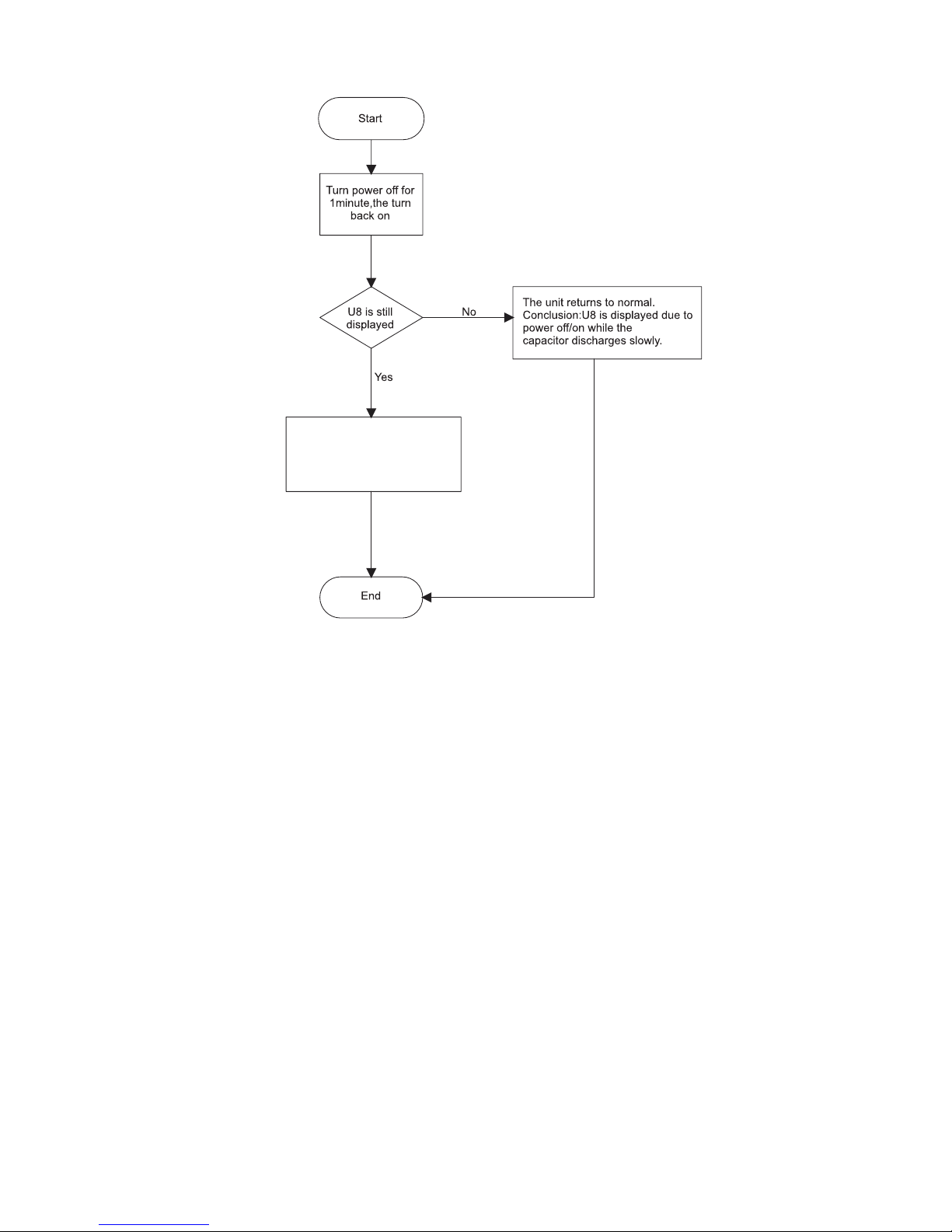
4.
Malfunction of Zero-crossing Inspection Circuit Malfunction of the IDU Fan Motor U8
The zero-cross detection circuit
of the main board is defined
abnormal.
Replace the main board.
Page 18
18
AY-X36RU
AE-X36RU
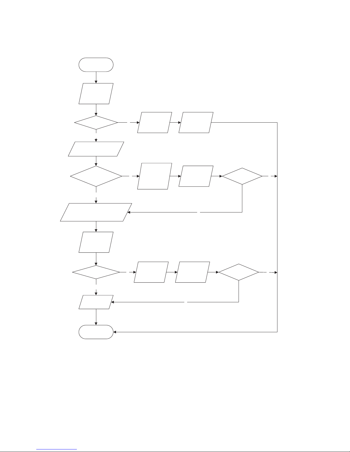
5.
Capacitor charge fault (Fault with outdoor unit) (AP1 the control panel of the outdoor unit)
Main Check Points:
● Use AC voltmeter to check if the voltage between terminal L and N on the wiring board is within 210VAC~240VAC.
● If the reactor (L) is correctly connected? If the connection is loose or fallen? If the reactor (L) is damaged?
N
Y
N
Y
N
Y
N
Y
N
Y
Turn on the unit
and wait 1 minute
Use DC voltmeter
to measure the
voltage on the two
ends of electrolytic
capacitor
Voltage higher than 200V?
Fault with the voltage
testing circuit on
control panel AP1
Replace the control
panel AP1
Measure the AC voltage between
terminal
L and N on wiring board
XT(power supply)
Voltage within
210VAC~250VAC?
Shut down the power
and repair the power
supply to restore the
range
210VAC~250VAC
power on and
restart the unit
Shut down the power and wait 20 mi
nutes;or
use DC voltmeter to measure the voltage
on the two ends of capacitor , until
the voltage is lower than 20V
Check the
connection of reactor
(L in the Electrical
Wiring Diagram)
If the wiring of
reactor L
is normal?
Connect the reactor
Laccording to Electrical Wiring Diagram correctly
Re-energize and
turn on the unit
End
Replace the control
panel AP1
Is the problem fixed?
Is the problem fixed?
Page 19
AY-X36RU
AE-X36RU
19
6.
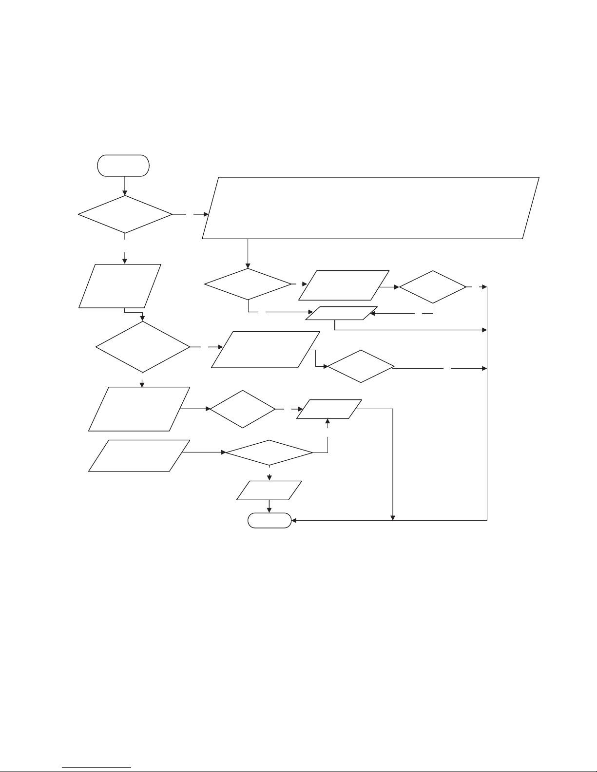
IPM Protection, Out-of-step Fault, Compressor Phase Overcurrent (AP1: the control panel of the
outdoor unit)
Main Check Points:
● If the connection between control panel AP1 and compressor COMP is secure? If loose? If the connection is in correct order?
● If the voltage input of the machine is within normal range? (Use AC voltmeter to measure the voltage between terminal L andN
on the wiring board XT)
● If the compressor coil resistance is normal? If the insulation of compressor coil against the copper tube is in good condition?
● If the working load of the machine are too high? If the radiation is good?
● If the charge volume of refrigerant is correct?
Energize and
switch on
IPM protection
occurs after the
machine has run for
a
p
eriod of time?
Please confirm:
1. If the indoor and outdoor heat exchangers are dirty? If they are obstructed by other objects which affect the
heat exchange of indoor and outdoor unit.
2. If the indoor and outdoor fans are working normally?
3. If the environment temperature is too high, resulting in that the system pressure is too high and exceeds the
permissible range?
4. If the charge volume of refrigerant is too much, resulting in that the system pressure is too high?
5. Other conditions resulting in that the system pressure becomes too high.
Take corrective actions
according to Technical
Service Manual, and
then energize and start
the unit.
If there is any
abnormality
described above?
Replace the
control panel AP1
If the connection
between AP1 and
COMP is unsecure
or the connection
order is wrong?
Connect the control panel
A
P1 and compressor
COMP correctly according
to the Electrical Wiring
Diagram. Then, energize
and start the unit.
Use ohmmeter to
measure the resistance
between the three
terminals on compressor
COMP, and compare the
measurements with the
compressor resistance on
Service Manual.
If the
resistance is
normal?
Use ohmmeter to
measure the resistance
between the two
terminals of compressor
COMP and copper tube.
Replace the
compressor
COMP
Resistance higher
than 500MΩ?
Replace the
control panel
AP1
END
If the unit can
work normally?
Y
Y
N
N
If the unit can
work
normally?
Y
Y
Y
N
N
Refer to the
Electrical Wiring
Diagram and check
if the connection
between AP1 and
COMP is loose and if
the connection order
is correct.
N
N
Page 20
20
AY-X36RU
AE-X36RU
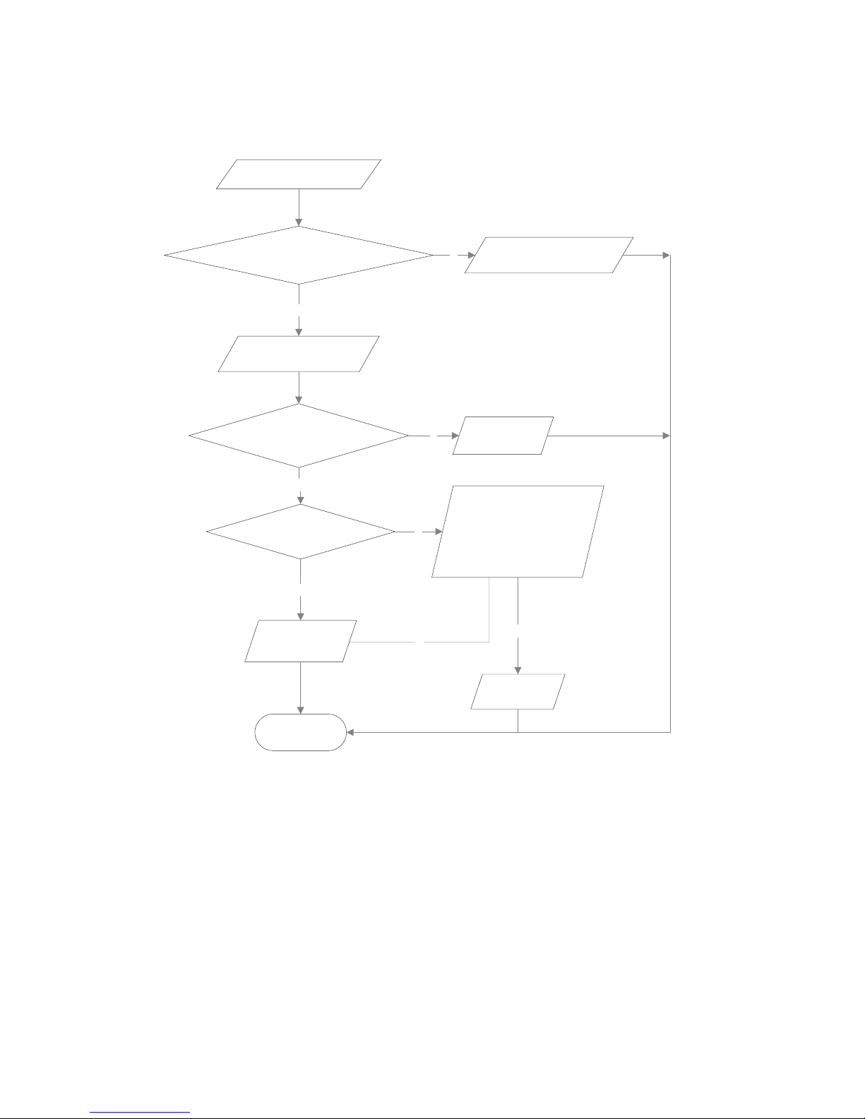
7.
High temperature and overload protection diagnosis (AP1: the control board of the outdoor unit)
Mainly detect:
● Is outdoor ambient temperature in normal range?
● Are the outdoor and indoor fans operating normally?
● Is the heat dissipation environment inside and outside the unit is good?
End
Y
Y
N
Y
N
N
Y
N
Overheat and high
temperature protection
Is outdoor ambient temperature higher than 53?
20 minutes after the complete
unit is powered off.
Is heat dissipation of the indoor unit
and outdoor unit abnormal?
Normal protection, please operate
it after the outdoor ambient temperature is normalized.
Improve the heat
dissipation environment of the unit
Does the outdoor fan work normally?
1. Check if the fan terminal OFAN
is connected correctly
2. Measure the electric resistance
between any two fan terminal by
ohmmeter, check if the value of
electric resistance is less than
1KOhm.
Replace the
control panel
AP1
Replace the
outdoor fan
Page 21
AY-X36RU
AE-X36RU
21
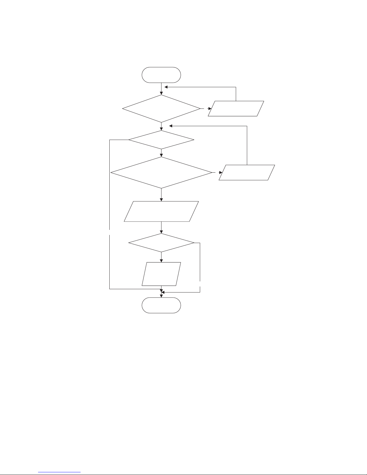
8.
Start-up failure (AP1: the control board of the outdoor unit)
Mainly detect:
● Whether the compressor wiring is connected correct?
● Is compressor broken?
● Is time for compressor stopping enough?
Y
N
Y
N
N
Y
Y
N
Power on the unit
Is stop time of the compressor
longer than 3 minutes?
Restart it up after
3 minutes
Does startup fail?
Are the wires for the compressor connected
correctly? Is connection sequence right?
Connect the wires as
per the connection
diagram
Replace the control panel AP1
Replace the
compressor
End
Is the problem fixed?
Page 22
22
AY-X36RU
AE-X36RU
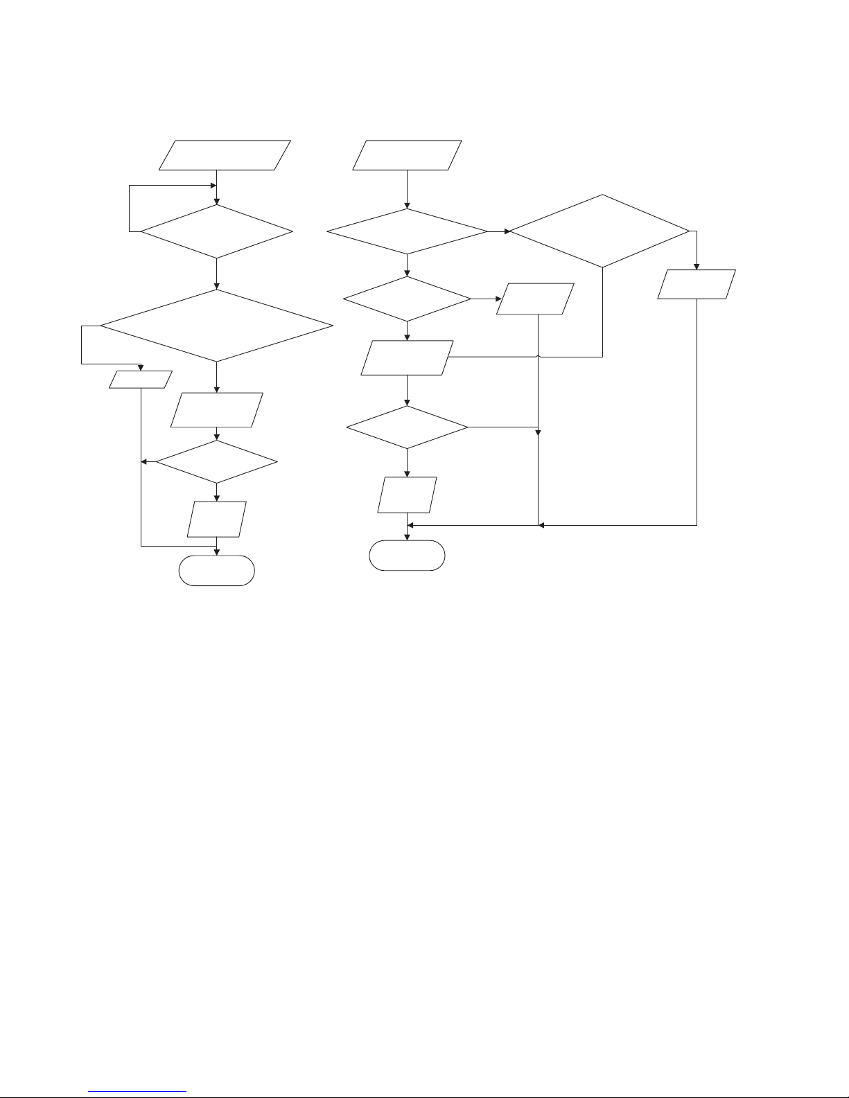
9.
Out of step diagnosis for the compressor (AP1: the control board of the outdoor unit)
Mainly detect:
● Whether the system pressure is too high?
● Whether the input voltage is too low?
Out of step occurs once the
unit is powered on.
Is stop time of the
compressor longer than
3 minutes?
Are the wires for the compressor connected
correctly? Is connection sequence right?
Is the connection made in clockwise
direction?
Connect the
wires correctly
Replace the control
panel AP1
Replace the
compressor
End
Out of step occurs in
operation
Is the outdoor fan working
normally?
Is the outdoor unit blocked
by any objects?
Replace the
control panel AP1
Replace the
compressor
End
Remove objects.
Replace the
outdoor fan
N
Y
Y
Y
Y
Y
Y
Y
N
N
N
N
N
N
Measure the
electric resistance between any two
fan terminal by ohmmeter, check if the value of
electric resistance is less than
1KOhm.
Is the problem fixed?
Is the problem fixed?
Page 23
AY-X36RU
AE-X36RU
23
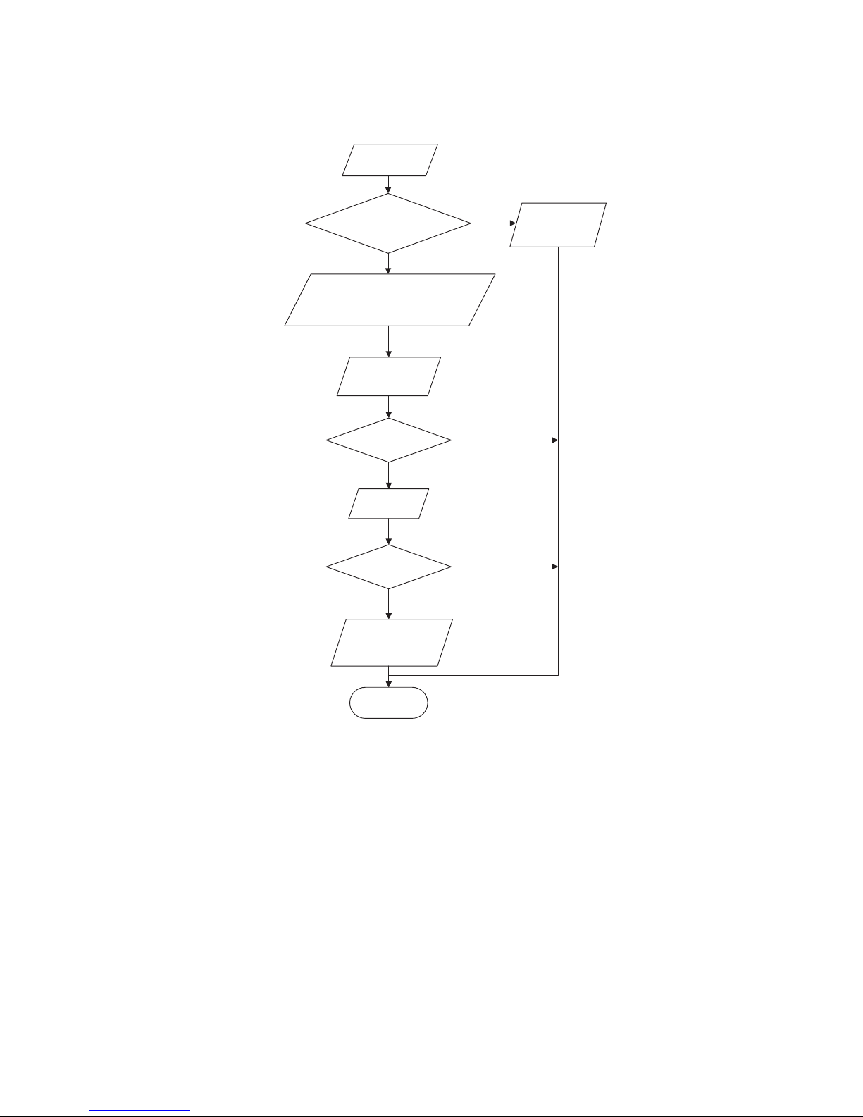
10.
Overload and air exhaust malfunction diagnosis (AP1: the control board of the outdoor unit)
Mainly detect:
● Wether the PMV is connected well or not? Is PMV damaged?
● Is refrigerant leaked?
20 minutes after the
complete unit is
powered off
Is the terminal FA for the
electronic expansion valve
connected correctly?
Connect the
N
N
N
Y
Y
Y
wires correctly
Resistances between the first four pins
close to the terminal hole and the fifth
pin are almost the same, less than 100
ohm.
Replace the electronic
expansion valve
Replace the
control panel
AP1
Coolant leakage, refilling
the coolant
End
Is the problem fixed?
Is the problem fixed?
Page 24
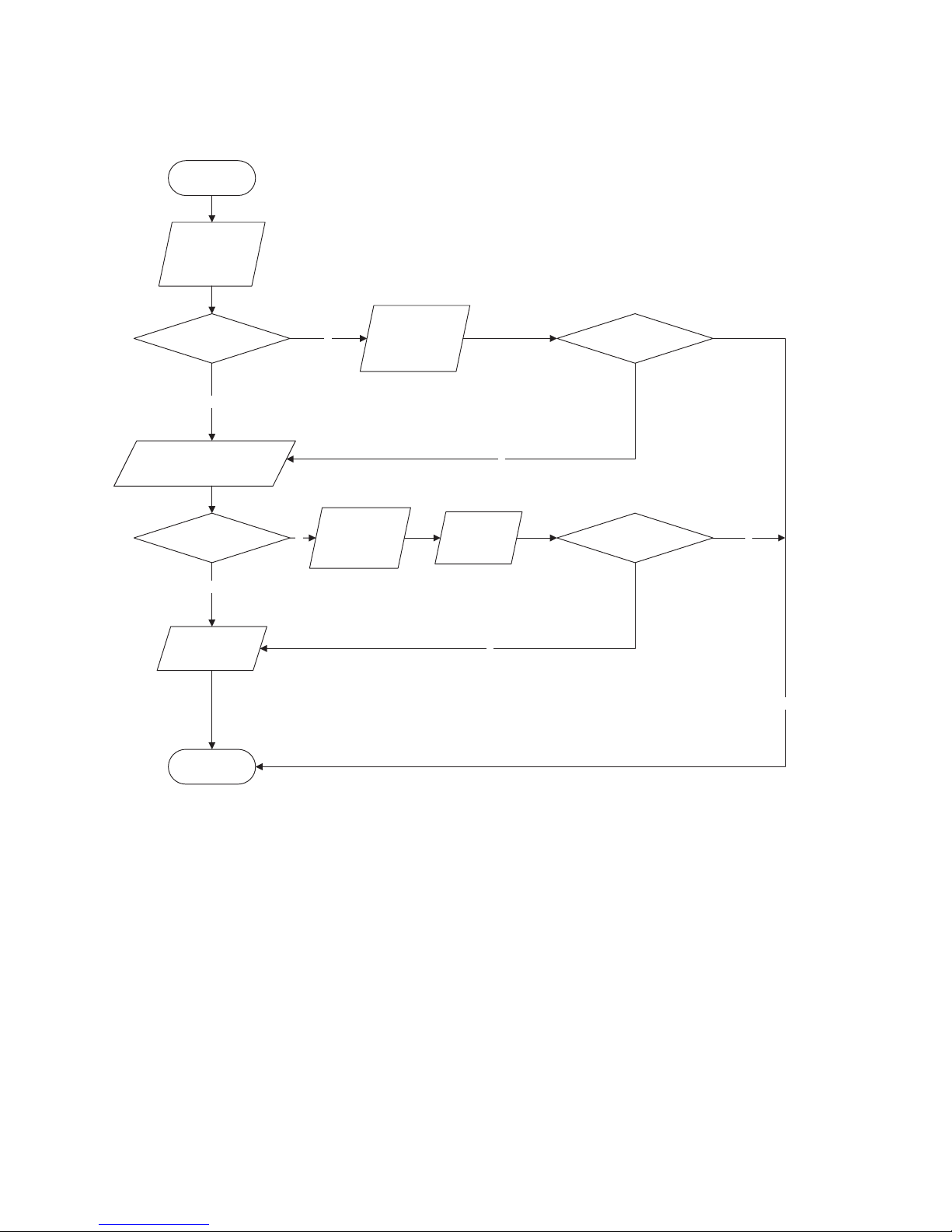
24
AY-X36RU
AE-X36RU
11.
Power factor correct or (PFC) fault (a fault of outdoor unit) (AP1: the control board of the outdoor
unit)
Mainly detect:
● Check if the reactor (L) of the outdoor unit and the PFC capacitor are broken
Y
N
N
N
N
Y
Y
Start
Check wiring of the
reactor (L) of the
outdoor unit and the
PFC capacitor
Whether there is any
damage or
short-circuit?
Replace it as per the
wiring diagram and
reconnect the wires
Disconnect the terminals for the
reactor and measure the resistance
between the two terminals of the
reactor by an ohm gauge
Whether there is any damage
or short-circuit?
Replace the reactor
Restart the unit
Replace the control
panel AP1
End
Y
Is the problem fixed?
Is the problem fixed?
Page 25
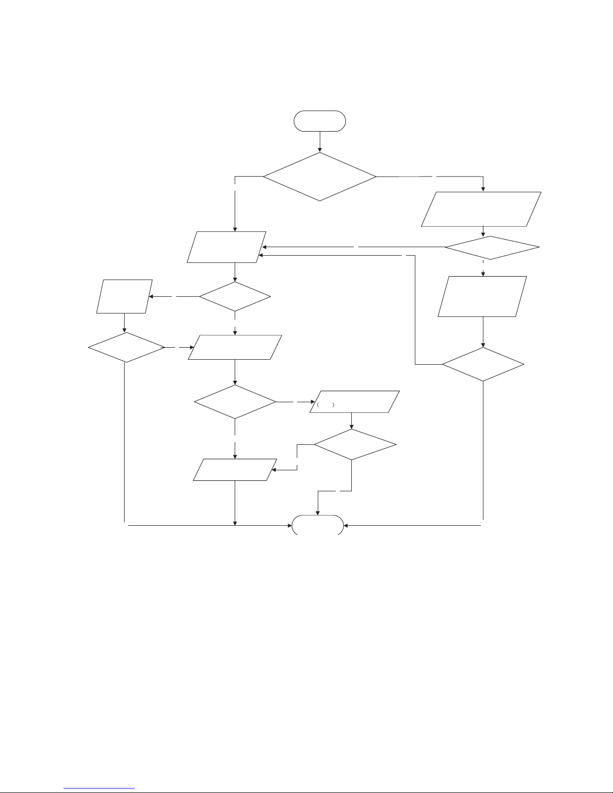
AY-X36RU
AE-X36RU
25
12.
Communication malfunction: (AP1: the control board of the outdoor unit)
Mainly detect:
● Is there any damage for the indoor unit mainboard communication circuit? Is communication circuit damaged?
● Detect the indoor and outdoor units connection wire and indoor and outdoor units inside wiring is connect well or not, if isthere
any damage?
Y
N
Y
N
N
Y
N
N
Y
N
Y
N
Y
Y
Start
Did the equipment operate
normally before the failure
occurs?
The AP1 voltage
detection circuit
is at fault
Check wiring inside of
the indoor and outdoor
units
Are wires broken?
Check the communication
circuit of the outdoor unit
The communication
circuit is abnormal
Replace the main board
of
the indoor unit
End
Replace the main board
AP1 of the outdoor unit
Is the connection right?
Check the wiring of the indoor and
outdoor units with reference to the
wiring diagram
Correctly connect the
corresponding wires for
the indoor and outdoor
units with reference to
the wiring diagram
Is the problem fixed?
Is the problem fixed?
Is the problem fixed?
Page 26
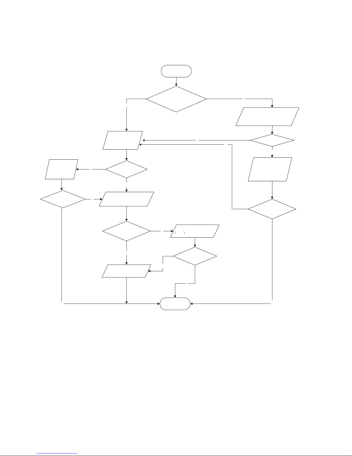
26
AY-X36RU
AE-X36RU
13.
Communication malfunction:(AP1: the control board of the outdoor unit)
Mainly detect:
Detect the indoor and outdoor units connection wire and indoor and outdoor units inside wiring is connect well or not, If is there
any damage?
Is there any damage for the indoor unit mainboard communication circuit? Is communication circuit damaged?
The ow chart r malfunction detect:
Y
N
Y
N
N
Y
N
N
Y
N
Y
N
Y
Y
Start
Did the equipment operate
normally before the failure
occurs?
The AP1 voltage
detection circuit
is at fault
Check wiring inside of
the indoor and outdoor
units
Are wires broken?
Check the communication
circuit of the outdoor unit
The communication
circuit is abnormal
Replace the main board of
the indoor unit
End
Replace the main board
AP1 of the outdoor unit
Is the connection right?
Check the wiring of the indoor and
outdoor units with reference to the
wiring diagram
Correctly connect the
corresponding wires for
the indoor and outdoor
units with reference to
the wiring diagram
Is the problem fixed?
Is the problem fixed?
Is the problem fixed?
Page 27
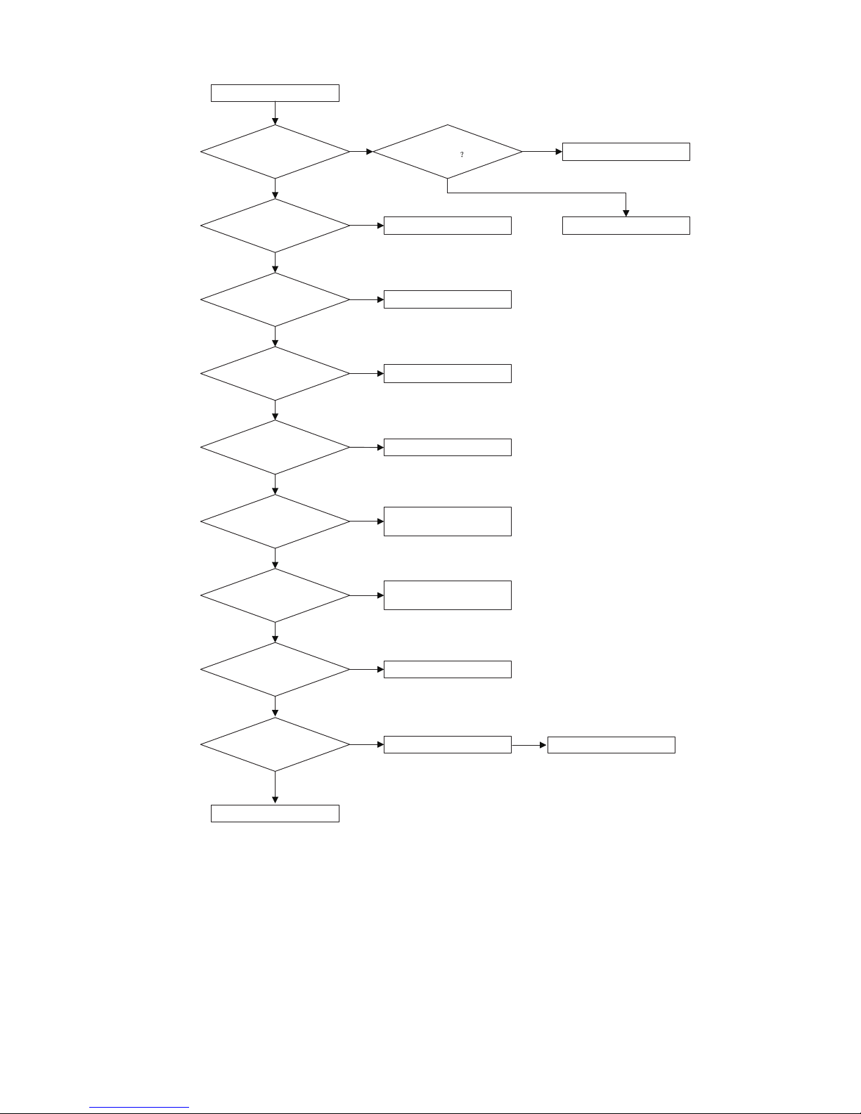
AY-X36RU
AE-X36RU
27
14.
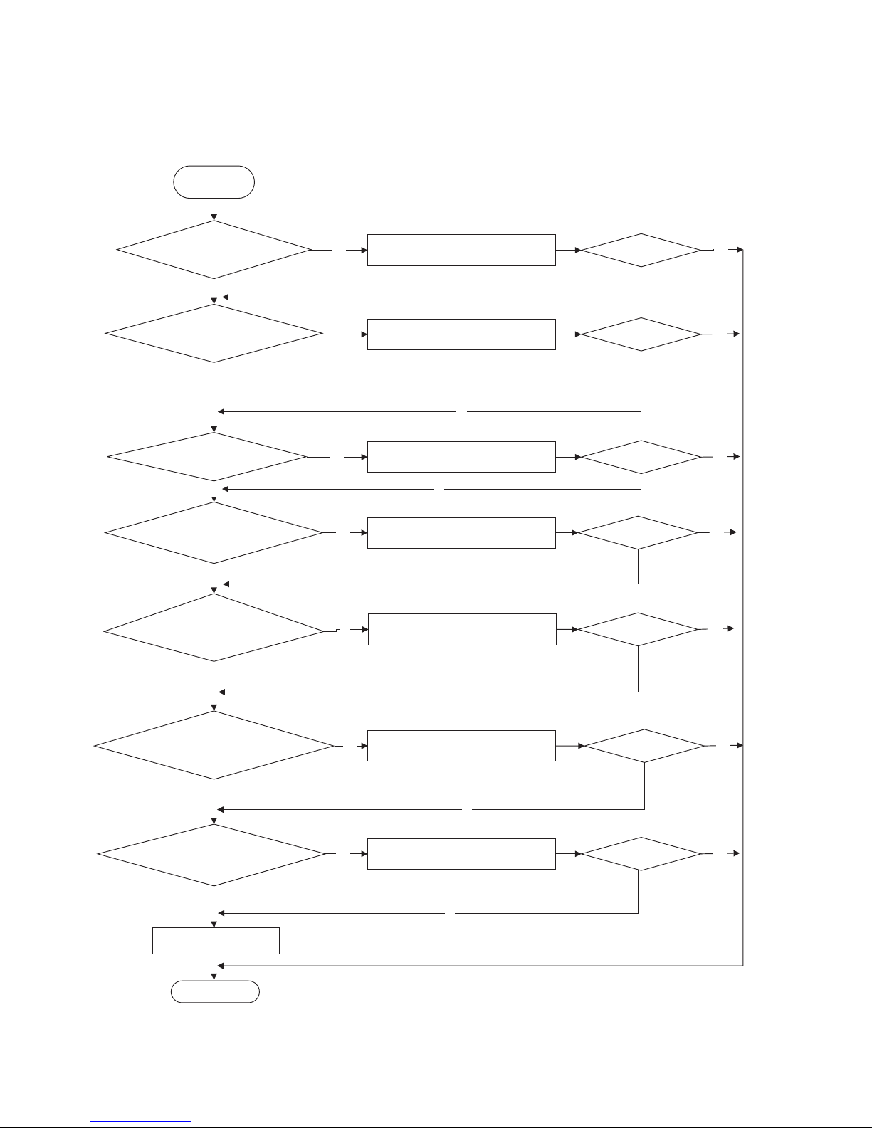
High-pressure Protection
High-pressure protection
Use pressure gauge to
measure if the pressure is
really high?
Check if the operation mode of
indoor unit is set properly?
Check if the gas valve and
liquid valve are fully open?
Check if the front panel of
outdoor unit is covered tightly?
Check if the air inlet and outlet of
the indoor and outdoor
exchanger is smooth ?
Check if the indoor and
outdoor fans operate normally?
Check if the indoor swing
louver is fully open?
Check if the capacity output of
outdoor unit is equal to the
capacity demand of indoor units?
Check if the indoor / outdoor
filters or radiating fins are dirty or
blocked ?
Clean the fins
The system pipe is blocked
Refer to the dial-up of indoor
and outdoor unit
Measure the swing motor and
signal input
Measure the fan motor and
signal input
Remove the obstructions
Cover up the front panel
properly
Fully open the valve
Set the correct operation
mode
Measure if the pressure switch
is normal
Replace the pressure switch
no
no
no
no
no
no
no
no
yesno
yes
yes
yes
yes
yes
yes
yes
yes
no
Replace the blocked parts or
pipe
no
Replace the mainboard of
outdoor unit
Page 28
28
AY-X36RU
AE-X36RU
15.
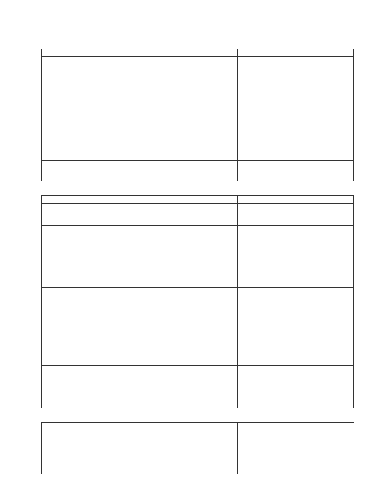
Malfunction of Over current Protection E5
Main detection points:
● EliminatedIs the supply voltage unstable with big uctuation?
● Is the supply voltage too low with overload?
● Hardware trouble?
no
no
no
no
yes
no
no
End
yes
Is the supply voltage unstable
with big fluctuation?
Is the supply voltage too low
with overload?
The fan is abnormal? Fan
speed is too low or fan doesn’t rotate
Measure the
current of live wireon the main
board with a clamp ampere meter. Is the
current higher than the value of the
overcurrent protection?
Is there blockage inside
the system? (Filth blockage, ice plug,
greasy blockage, the Y-valve hasn’t been opened
completely)
Is the compressor running
abnormally? Is there abnormal sound or oil
leakage; is the temperature of the shell
too high, etc.?
Is the indoor / outdoor
heat exchanger too dirty,or are the air inlet
and outlet blocked?
Normal fluctuation is within 10 % of the rated
voltage on the nameplate
.
no
yes
.
no
yes
.
no
yes
no
no
no
yes
no
yes
.
no
yes
yes
yes
yes
yes
yes
yes
Troubleshooting
for E5 malfunction
Adjust the supply voltage to maintain it within
normal range
Clean the indoor and outdoor heat exchangers
and remove the blockage of air inlet and outlet
Check the motor and reinstall the motor to have
the fan run normally
Flush the heat exchangers with high pressure
nitrogen
Is the problem fixed?
Is the problem fixed?
Is the problem fixed?
Is the problem fixed?
Is the problem fixed?
Is the problem fixed?
Is the problem fixed?Replace the main board.
Replace the main board.
Replace the main board.
Page 29
AY-X36RU
AE-X36RU
29
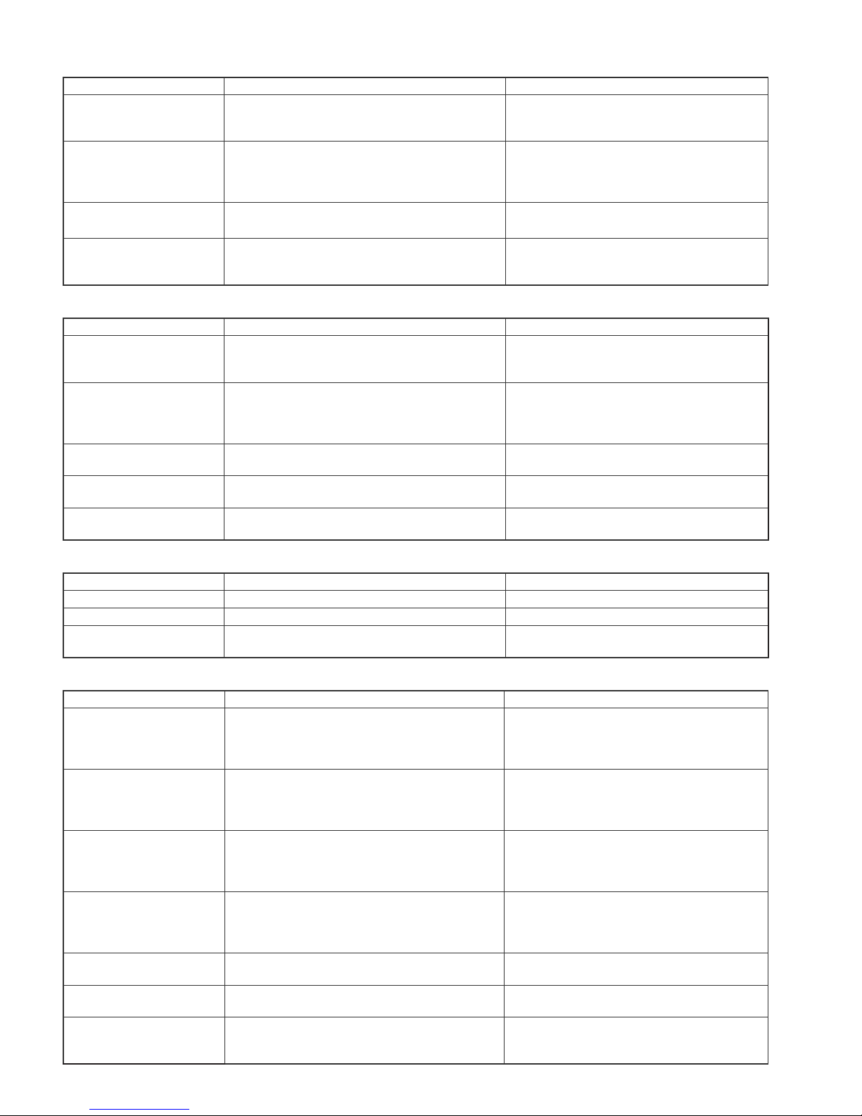
[3] Troubleshooting for Normal Malfunction
1.
Air conditioner can’t be started up
Possible Causes Discriminating Method (Air conditioner Status) Troubleshooting
No power supply, or poor connection for power plug
After energization, operation indicator isn’t bright
and the buzzer can’t give out sound.
Conrm whether it’s due to power failure. If yes,
wait for power recovery. If not, check power
supply circuit and make sure the power plug is
connected well.
Wrong wire connection
between indoor unit and outdoor unit, or poor connection
for wiring terminals.
Under normal power supply circumstances, operation indicator isn’t bright after energization.
Check the circuit according to circuit diagram
and connect wires correctly. Make sure all wir-
ing terminals are connected rmly.
Electric leakage for air conditioner.
After energization, room circuit breaker trips off at
once.
Make sure the air conditioner is grounded reliably.
Make sure wires of air conditioner is connected
correctly. Check the wiring inside air conditioner.
Check whether the insulation layer of power cord
is damaged; if yes, place the power cord.
.
Model selection for air switch
is improper.
After energization, air switch trips off Select proper air switch.
Malfunction of remote controller.
After energization, operation indicator is bright,
while no display on remote controller or buttons
have no action.
Replace batteries for remote controller.
Repair or replace remote controller.
2.
Poor Cooling (Heating) for Air Conditioner
Possible Causes Discriminating Method (Air conditioner Status) Troubleshooting
Set temperature is improper.
Observe the set temperature on remote controller. Adjust the set temperature.
Rotation speed of the IDU
fan motor is set too low.
Small wind blow. Set the fan speed at high or medium.
Filter of indoor unit is blocked.
Check the lter to see it's blocked. Clean the lter.
Installation position for
indoor unit and outdoor unit
is improper.
Check whether the installation position is proper
according to installation requirement for air conditioner.
Adjust the installation position, and install the
rainproof and sun-proof for outdoor unit.
Refrigerant is leaking.
Discharged air temperature during cooling is higher
than normal discharged wind temperature; Discharged air temperature during heating is lower
than normal discharged wind temperature; Unit's
pressure is much lower than regulated range.
Find out the leakage causes and deal with it.
Add refrigerant.
Malfunction of 4-way valve. Blow cold wind during heating. Replace the 4-way valve.
Malfunction of capillary.
Discharged air temperature during cooling is higher
than normal discharged wind temperature; Discharged air temperature during heating is lower
than normal discharged wind temperature; Unit’t
pressure is much lower than regulated range. If
refrigerant isn’t leaking, part of capillary is blocked.
Replace the capillary.
Flow volume of valve is
insufcient.
The pressure of valves is much lower than that stat-
ed in the specication.
Open the valve completely.
Malfunction of horizontal louver.
Horizontal louver can’t swing.
Refer to point 3 of maintenance method for
details.
Malfunction of the IDU fan
motor
The IDU fan motor can’t operate.
Refer to troubleshooting for H6 for maintenance
method in details
Malfunction of the ODU fan
motor
The ODU fan motor can't operate.
Refer to point 4 of maintenance method for
details.
Malfunction of compressor Compressor can't operate.
Refer to point 5 of maintenance method for
details.
3.
Horizontal Louver Can’t Swing
Possible Causes Discriminating Method (Air conditioner Status) Troubleshooting
Wrong wire connection, or
poor connection
Check the wiring status according to circuit diagram.
Connect wires according to wiring diagram to
make sure all wiring terminals are connected
rmly
Stepping motor is damaged Stepping motor can't operate Repair or replace stepping motor
Main board is damaged Others are all normal, while horizontal louver can't
operate
Replace the main board with the same model
Page 30
30
AY-X36RU
AE-X36RU
4.
ODU Fan Motor Can’t Operate
Possible causes Discriminating method (air conditioner status) Troubleshooting
Wrong wire connection, or
poor connection.
Check the wiring status according to circuit diagram.
Connect wires according to wiring diagram to
make sure all wiring terminals are connected
rmly.
Capacity of the ODU fan
motor is damaged.
Measure the capacity of fan capacitor with an universal meter and find that the capacity is out of the
deviation range indicated on the nameplate of fan
capacitor.
Replace the capacity of fan.
Power voltage is a little low
or high.
Use universal meter to measure the power supply
voltage. The voltage is a little high or low
Suggest to equip with voltage regulator.
Motor of outdoor unit is damaged.
When unit is on, cooling/heating performance is bad
and ODU compressor generates a lot of noise and
heat.
Change compressor oil and refrigerant. If no
better, replace the compressor with a new one.
5.
Compressor Can’t Operate
Possible causes Discriminating method (air conditioner status) Troubleshooting
Wrong wire connection, or
poor connection.
Check the wiring status according to circuit diagram Connect wires according to wiring diagram to
make sure all wiring terminals are connected
rmly.
Capacity of compressor is
damaged.
Measure the capacity of fan capacitor with an universal meter and find that the capacity is out of the
deviation range indicated on the nameplate of fan
capacitor.
Replace the compressor capacitor.
Power voltage is a little low
or high.
Use universal meter to measure the power supply
voltage. The voltage is a little high or low.
Suggest to equip with voltage regulator.
Coil of compressor is burnt
out.
Use universal meter to measure the resistance
between compressor terminals and it's 0.
Repair or replace compressor.
Cylinder of compressor is
blocked.
Compressor can't operate. Repair or replace compressor.
6.
Air Conditioner is Leaking
Possible causes Discriminating method (air conditioner status) Troubleshooting
Drain pipe is blocked. Water leaking from indoor unit.
Eliminate the foreign objects inside the drain pipe.
Drain pipe is broken. Water leaking from drain pipe. Replace drain pipe
Wrapping is not tight. Water leaking from the pipe connection place of
indoor unit.
Wrap it again and bundle it tightly.
7.
Abnormal Sound and Vibration
Possible causes Discriminating method (air conditioner status) Troubleshooting
When turn on or turn off the
unit, the panel and other
parts will expand and there's
abnormal sound.
There's the sound of "PAPA". Normal phenomenon. Abnormal sound will dis-
appear after a few minutes.
When turn on or turn off the
unit, there's abnormal sound
due to flow of refrigerant
inside air conditioner.
Water-running sound can be heard. Normal phenomenon. Abnormal sound will dis-
appear after a few minutes.
Foreign objects inside the
indoor unit or there are parts
touching together inside the
indoor unit.
There's abnormal sound fro indoor unit. Remove foreign objects. Adjust all parts' position
of indoor unit, tighten screws and stick damping
plaster between connected parts.
Foreign objects inside the
outdoor unit or there are
parts touching together
inside the outdoor unit.
There's abnormal sound fro outdoor unit. Remove foreign objects. Adjust all parts' position
of outdoor unit, tighten screws and stick damping plaster between connected parts.
Short circuit inside the magnetic coil.
During heating, the way valve has abnormal electromagnetic sound.
Replace magnetic coil.
Abnormal shake of compressor.
Outdoor unit gives out abnormal sound. Adjust the support foot mat of compressor, tight-
en the bolts.
Abnormal sound inside the
compressor.
Abnormal sound inside the compressor If add too much refrigerant during maintenance,
please reduce refrigerant properly. Replace
compressor for other circumstances.
Page 31
AY-X36RU
AE-X36RU
31
REFRIGERATION CYCLE
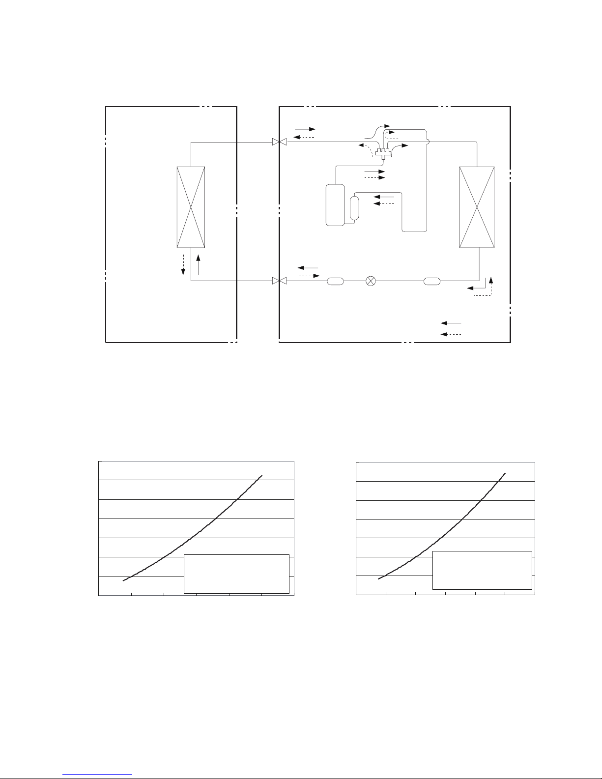
[1] Refrigerant System Diagram
Indoor unit
Outdoor unit
COOLING
HEATING
4-Way valve
Discharge
Suction
Heat
exchanger
(evaporator)
Heat
exchanger
(condenser)
Valve
Valve
Liquid pipe
side
Gas pipe
side
Strainer
Electron
expansion
valve
Strainer
Accumlator
Compressor
Connection pipe specication:
Liquid pipe:1/4 inch (6.35mm)
Gas pipe:5/8 inch (16mm)
[2] PERFORMANCE CURVES
1. Operation Characteristic Curve
Cooling
Heating
0
2
4
6
8
10
12
14
0 20 40 60 80 100 120
0
2
4
6
8
10
12
14
0 20 40 60 80 100 120
Conditio
n
Indoor:DB 80.6°F
WB66.2
°F
Indoor air flow: Super High
Pipe length:24.6ft
Condition
Indoor:DB 70°F
Indoor air flow: Super High
Pipe length:24.6ft
Compressor Frequency(Hz)
Compressor Frequency(Hz)
Current(A)
Current(A)
Page 32
32
AY-X36RU
AE-X36RU
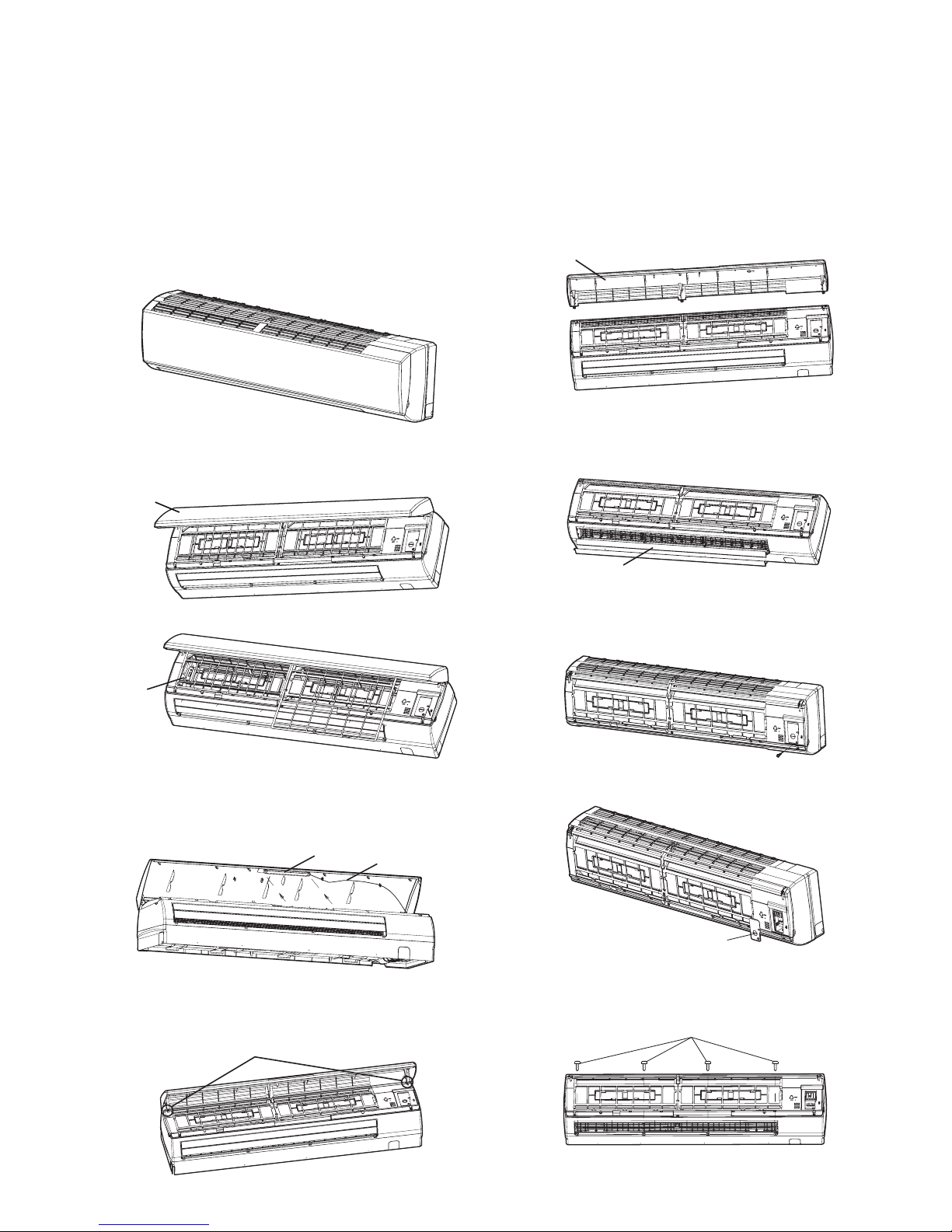
2. Capacity Variation Ratio According to Temperature
90 95 100 105 110
5 10 15 20 25 30 35
40
45 50
100
105
95
90
85
80
75
70
65
60
55
50
Outdoor temp. (˚F)
Capacity ratio (%)
110
100
90
80
70
60
50
40
Outdoor temp. (˚F)
Capacity ratio (%)
Conditions
Indoor:
Pipe length :
24.6ft
DB 80.6°F
WB66.2
°F
Condition
Indoor:DB 70°F
Indoor air flow: Super High
Indoor air flow: Super High
Pipe length:24.6ft
Cooling
Heating
3. Cooling and Heating Data Sheet in Rated Frequency
Cooling:
Rated cooling condition
(°F) (DB/WB)
Pressure of gas pipe connect-
ing indoor and outdoor unit
Inlet and outlet pipe temper-
ature of heat exchanger
Fan speed of
indoor unit
Fan speed of
outdoor unit
Compressor
revolution (rps)
Indoor Outdoor P (MPa) T1 (°F) T2 (°F)
80/66.9 95/- 0.9 ~1.0 46.8 to 52.8 127 to 96.8 Supper High High 67
Heating:
Rated cooling condition
(°F) (DB/WB)
Pressure of gas pipe connect-
ing indoor and outdoor unit
Inlet and outlet pipe temper-
ature of heat exchanger
Fan speed of
indoor unit
Fan speed of
outdoor unit
Compressor
revolution (rps)
Indoor Outdoor P (MPa) T1 (°F) T2 (°F)
70/- 19.94/19.04 3.5 ~3.8 134.4 to 102 36 to 39 Supper High High 61
Instruction:
T1: Inlet and outlet pipe temperature of evaporator
T2: Inlet and outlet pipe temperature of condenser
P: Pressure at the side of big valve
Connection pipe length: 24.6ft.
Page 33
AY-X36RU
AE-X36RU
33
DISASSEMBLY PROCEDURE
Be sure to turn off the circuit breaker before disassembly procedure. When reassembling the unit after repairing, be sure to install
screws to their original positions.
The screws used are not the same in specications such as corrosion-resistant treatment, tip shape and length.
After the air conditioner is repaired or parts are replaced, measure insulation resistance of the equipment using an insulation resistance meter. If the measured resistance is lower than 1 MW, inspect parts and repair or replace defective parts.
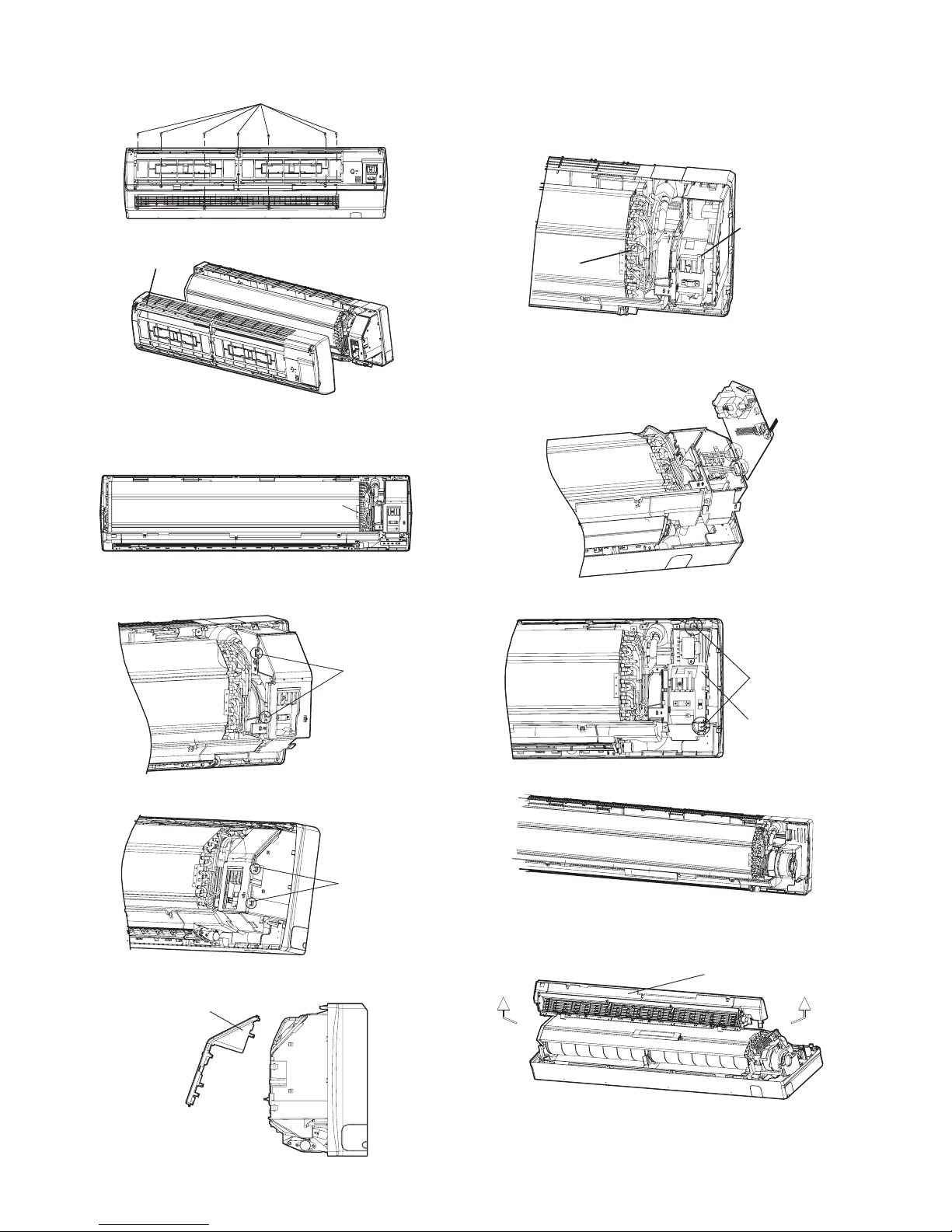
[1] INDOOR UNIT
1.
Before disassembly of the unit.
Axonometric drawing for the completeunit.
2.
Remove the lters.
1) Open the panel.
panel
2) Remove the two (2) lters.
filter
3.
Remove the display.
Remove the two (2) screws xing display, and then remove
the display with lead wire.
Display
Lead wire
4.
Remove the panel.
Pull the hooks at both sides slightly, and then remove the
panel.
Hook
Panel
5.
Remove the horizontal louver.
Remove the axial bush on the horizontal louver, and then
remove the horizontal louver.
Horizontal louver
6.
Remove the top cover of the electric box.
1) Remove the screw fixing the top cover of the electric
box.
Screw
2) Remove the top cover of the electric box.
Top cover of
the electric box
7.
Remove the front case.
1) Remove the four (4) screw caps on the front case.
Screw cap
Page 34
34
AY-X36RU
AE-X36RU
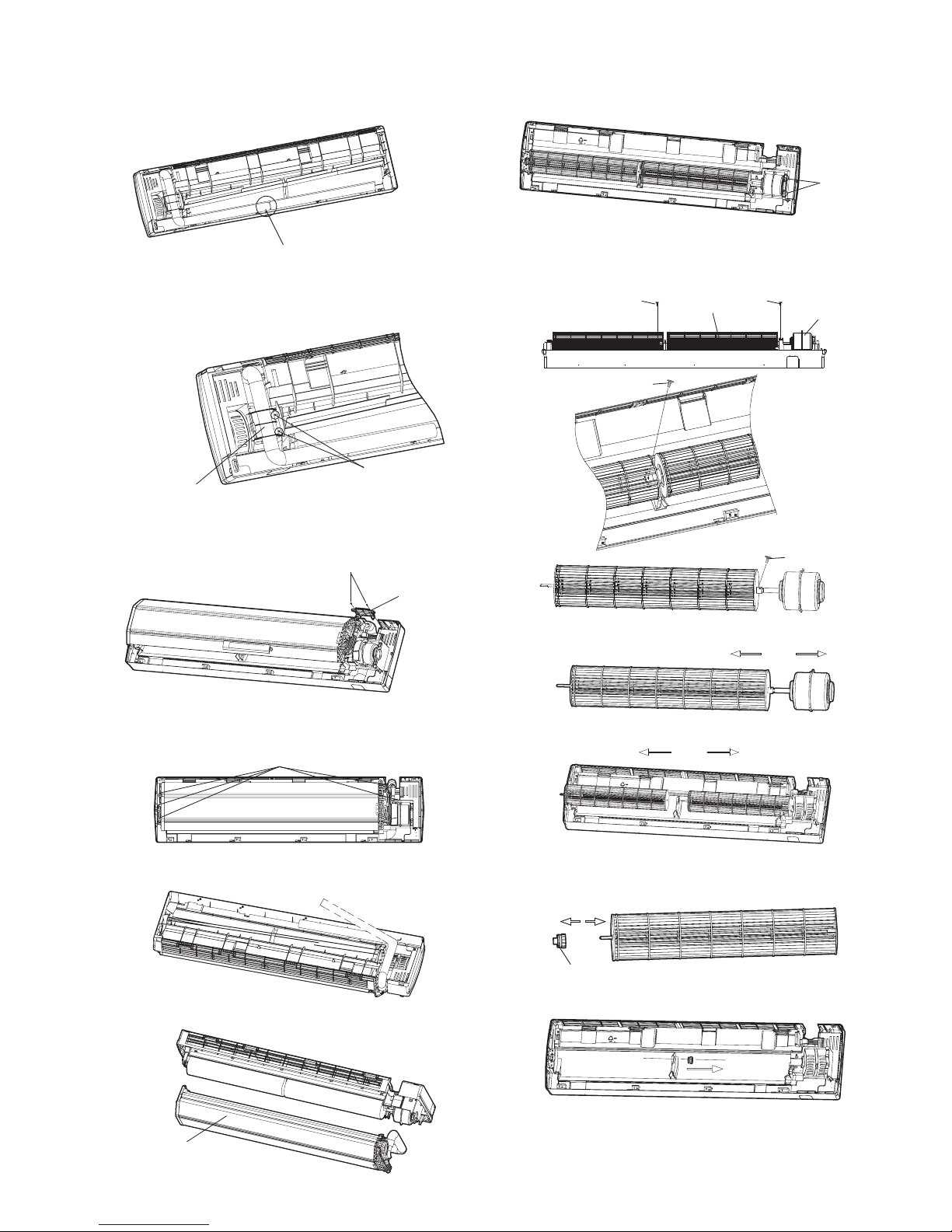
2) Remove the seven (7
)
screws connecting the front case.
Screw
3) Remove the front case.
Front case
8.
Remove the earthing wire .
Remove the earth screw and cut the xing band, and then
remove the earth wire.
screw
9.
Remove electric box cover.
1) Loosen hooks at the left side of the electric box.
Hook
2) Loosen the hooks on the right side of the electric box.
Hook
3) Remove the electric box cover.
Electric box cover
10.
Remove the temperature sensor and the earth
wire.
1) Pull out the indoor temperature sensor.
2) Remove the earth screw, and then remove the earth
wire.
Temperature
sensor
Earth
screw
11.
Remove the electric box.
1) Pull out the six (6) connectors on PCB board.
2) Remove the two (2) screws on the electric box.
Screw
Electric box
3) Remove the electric box.
12.
Remove the water tray.
Pull the water tray upwards, and then remove the water tray.
Water tray
Page 35
AY-X36RU
AE-X36RU
35
13.
Remove the connection pipe between indoor
and outdoor units.
Separate the connection pipe betweenindoor and outdoor
units.
Connection position for indoor and outdoor units' connection pipe
14.
Remove the pipe-stopping plate.
Remove the two (2) screws on the pipe-stopping plate for the
indoor unit, and then remove the pipe-stopping plate.
Pipe-stopping plate
Screw
15.
Remove the damping board.
Remove the two (2) screws on the damping board, and then
remove the damping board.
Screw
Damping board
16.
Remove the evaporator.
1) Remove the six (6) screws between evaporator and
bottom case.
Screws
2) Turn over the indoor unit and adjust the pipe line to the
position as shown by the broken line.
3) Lift up the evaporator, and then remove the evaporator.
Evaporator
17.
Remove the xing plate of motor.
Remove the two (2) screws on the xing plate of motor, and
then remove the xing plate of motor.
Screw
18.
Remove the cross ow fan and motor.
1) Remove the two (2) screws fixing cross flow fan and
motor.
Blade
Motor
Screw
Screw
Screw
Screw
2) Remove the motor sub-assy.
3) Separate the two (2) cross ow fans.
19.
Remove the cushion rubber.
1) Remove the cushion rubber on the cross ow fan.
Cushion rubber
2) Remove the cushion rubber from the base.
Page 36
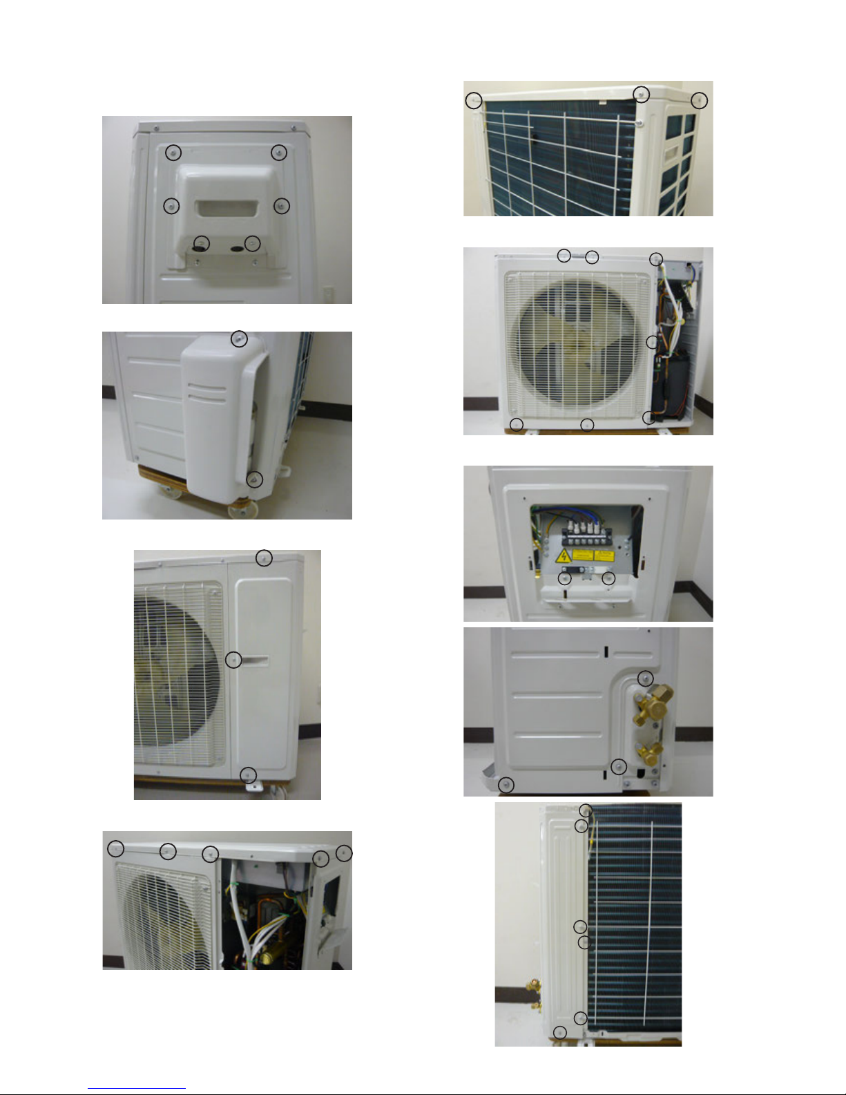
36
AY-X36RU
AE-X36RU
[2] OUTDOOR UNIT
PROCEDURE
1. Remove the six (6) screws xing the terminal cover.
2. Remove the two (2) screws xing the pipe cover.
3. Remove the three (3) screws xing the Front Side Plate
4. Remove the eight (8) screws xing the top plate.
5. Remove the seven (7) screws xing the front panel.
6. Remove the eleven (11) screws xing the right side panel.
Page 37
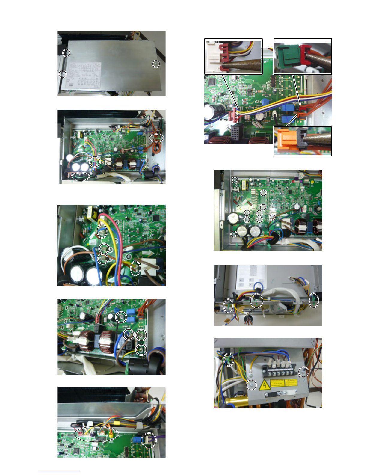
AY-X36RU
AE-X36RU
37
7. Remove the three (3) screws xing the control box cover.
8. Cut the three (3) xing bands.
9. Disconnect the connectors.
9-1. Disconnect the seven (7) connectors.
9-2. Disconnect the four (4) connectors.
9-3. Disconnect the six (6) connectors.
9-4. Disconnect the three (3) connectors after removing the
lock part.
10. Remove the nine (9) screws xing the PWB.
11. Loosen the three (3) xing bands xing the lead wire.
12. Cut the xing band and unscrew the two (2) screws
Page 38
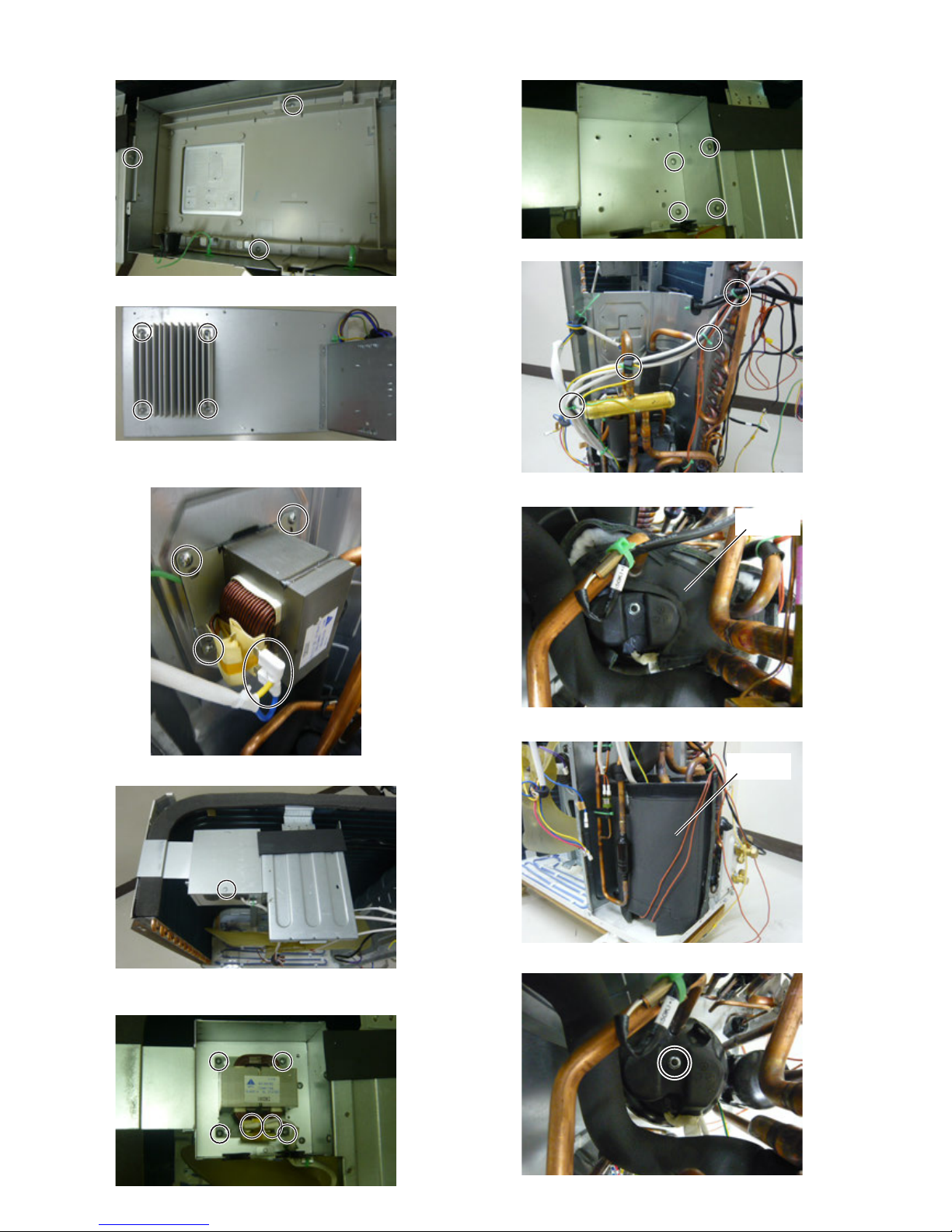
38
AY-X36RU
AE-X36RU
13. Remove the three (3) screws xing the control box assembly.
14. Remove the four (4) screws xing the heat sink.
15. Disconnect the two (2) connectors and remove the three (3)
screws xing the reactor.
16. Remove the one (1) screw xing the reactor box cover.
17. Disconnect the two (2) connectors and remove the four (4)
screws xing the reactor.
18. Remove the four (4) screws xing the reactor box.
19. Cut the four (4) xing bands.
20. Remove the topside compressor cover.
21. Remove the compressor cover.
22. Remove the nut xing the terminal cover.
Compressor
cover
Compressor
cover
Page 39
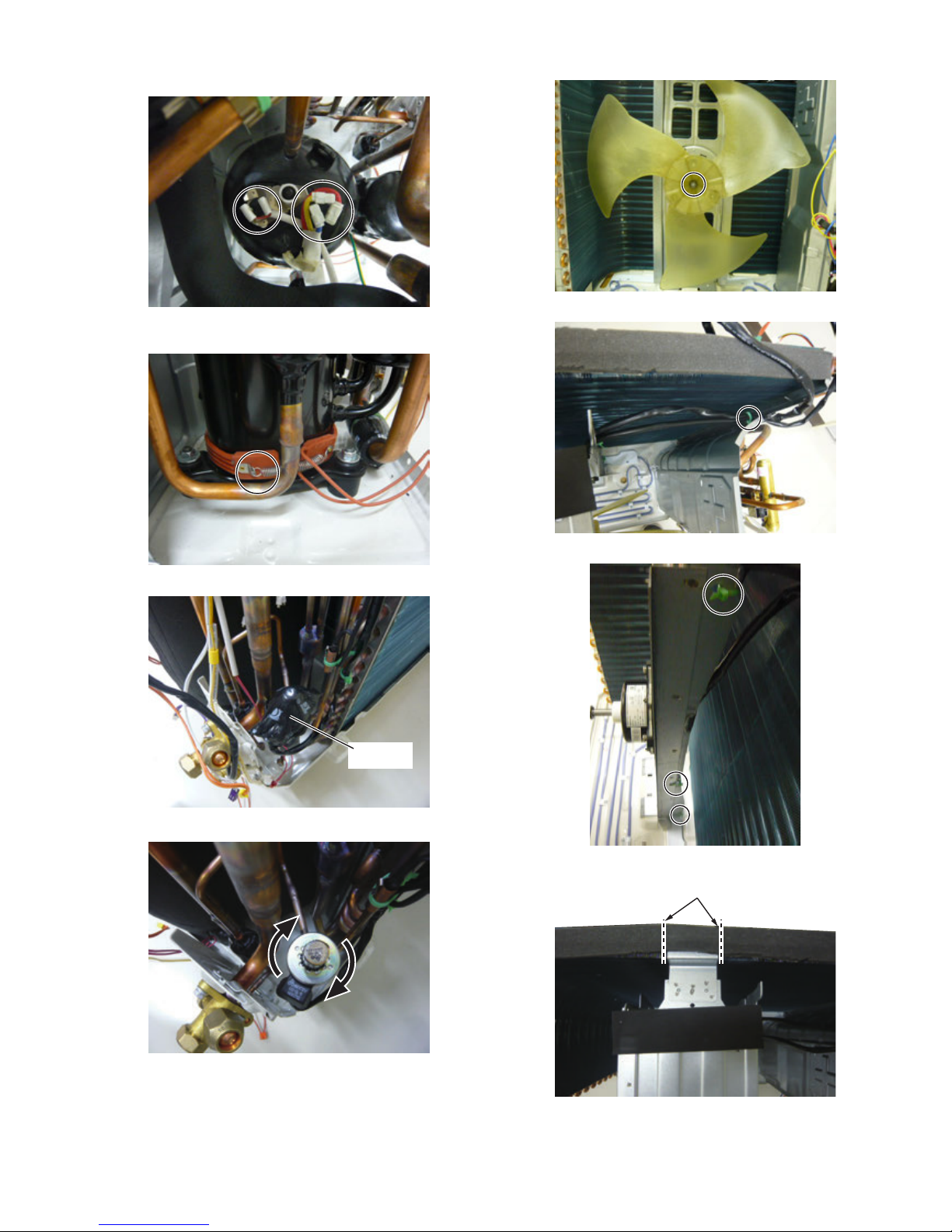
AY-X36RU
AE-X36RU
39
23. Disconnect the three (3) terminals (compressor lead wire)
and the two (2) terminals (thermistor lead wire).
24. Unhook the hook of the spring fixing the compressor heater
assembly.
25. Remove the damper rubber.
26. Turn the coil and remove it.
27. Remove the nut xing the propeller fan.
28. Loosen the xing band xing the lead wire.
29. Cut the three (3) xing bands.
30. Cut the insulator.
Cut
Damper
rubber
Page 40
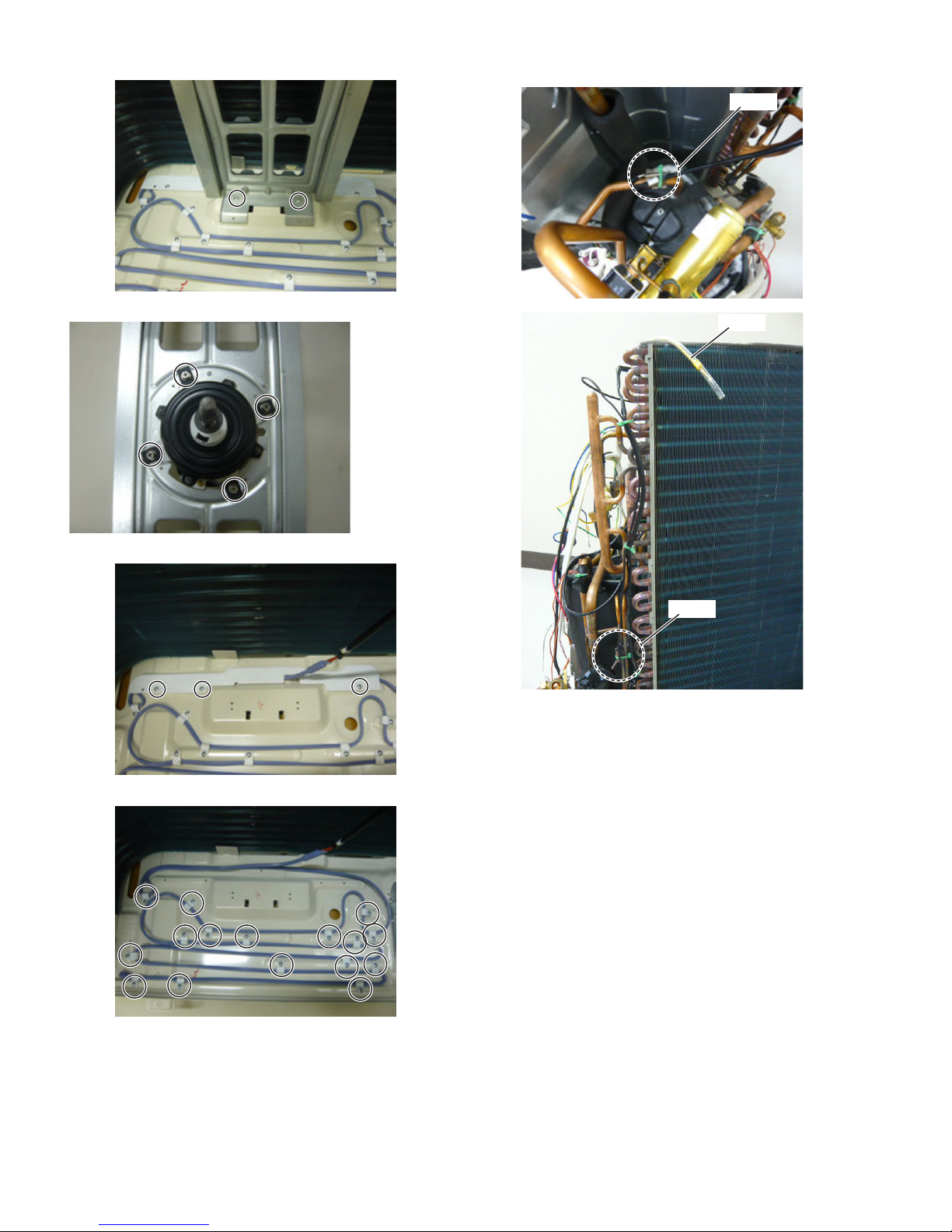
40
AY-X36RU
AE-X36RU
31. Remove the two (2) screws xing the motor angle.
32. Remove the four (4) screws xing the fan motor.
33. Remove the three (3) screws xing the heater cover.
34. Remove the sixteen (16) screws xing the heater assembly.
Position of the thermistors.
White
Yellow
Black
Page 41
PartsGuide
AYX36RU
PARTS LIST
SPLIT TYPE ROOM AIR CONDITIONER
MODELS
[1] INDOOR UNIT
[2] OUTDOOR UNIT
INDOOR UNIT
AY-X36RU
CONTENTS
OUTDOOR UNIT
AE-X36RU
INDEX
HOW TO ORDER REPLACEMENT PARTS
To have your order filled promptly and correctly, please
furnish the following information.
Parts marked with " " are important for maintaining the safety of the set. Be sure to replace these
parts with specified ones for maintaining the safety and performance of the set.
1. MODEL NUMBER
2. REF. NO.
3. PART NO.
4. DESCRIPTION
This document has been published to be used
for after sales service only.
The contents are subject to change without notice.
Page 42

AYX3 6RU
60
40
36
49
50
59
55
39
38
54
41
53
52
31
1
2
3
4
5
7
7
48
7
6
32
33
34
12
19
15
23
27
22
14
13
13
13
28
29
13
21
44
20
42
58
57
47
46
4561
43
26
30
18
17
16
24
25
35
37
51
56
11
10
9
8
[1] INDOOR UNIT
2
Page 43
NO. PARTS CODE
PRICE
RANK
NEW
MARK
PAR T
RANK
DESCRIPTION
[1] INDOOR UNIT
1 9JX20012712-L2 BE Front Panel Assy
2 9JX24212120 AC Stand Bar
3 9JX11122106 AM Filter Sub-Assy
4 9JX20022159 BD Front Case Sub-assy
5 9JX10512166 AL Upper Guide Louver
6 9JX10512167 AL Lower Guide Louver
7 9JX10542704 AC Axile Bush
8 9JX10512169 AC Air Louver 2
9 9JX10512168 AC Air Louver 1
10 9JX10582086 AC Connecting Rod
11 9JX26112158 AC Louver Clamp
12 9JX20182138 AY Water Tray
13 9JX242520053 AC Screw Cover
14 9JX76712012 AC Rubber Plug (Water Tray)
15 9JX22202928 BR Rear Case Assy
16 9JX10352039 AZ Cross Flow Fan 1
17 9JX26152028 AG Bearing Holder Sub-Assy
18 9JX10352040 AZ Cross Flow Fan 2
19 9JX76512203 AF O-Gasket of Cross Fan Bearing
20 9JX24212041 AH Left Evaporator Support
21 9JX01100100191 CF Evaporator Assy
22 9JX7508003810 AF (PE)Heat Insulating Hose
23 9JX01252398 AV Wall Mounting Frame
24 9JX1501213401 BX Fan Motor
25 9JX2421204201 AG Right Support of Evaporator
26 9JX26112071 AF Pipe Clamp
27 9JX0523001404 AL Drainage Hose
28 9JX20122124 AF Cover Plate
29 9JX26112325 AC Motor Fixed Clip 2
30 9JX26112324 AF Motor Fixed Clip 1
31 9JX1521210701 AR SteppingMotor
32 9JX26112070 AC Press Plate(Crank)
33 9JX10582041 AC Crank-Guide
34 9JX10562004 AC
35 9JX10562005 AC Lower Crank
36 9JX10000201845 BR Electric Box Assy
37 9JX201022502 AV Electric Box
38 9JX4201026902 AR Terminal Board
39 9JX30138000192 BM Main Board
40 9JX30565124 AX Display Board
41 9JX2011204404S AL Electric Box Cover
42 9JX30510475-L2 BC Remote Controller
43 9JX05212423 AC Temp Sensor Sleeving
44 9JXMC207059-L2 BP Wired Controller
45 9JX66129916746 AK Operation Manual
46 9JX66129916747 AN Installation Manual
47 9JX66129916748 AH Operation Manual (Wired Controller)
48 9JX01472023 AN Grill 2
49 9JX63229956735 AD Name Label
50 9JX390000592 AL Temp Sensor (for Heat Exchanger Temperature)
51 9JX71010103 AB Wire Clamp
52 9JX01592034 AL Lower Shield Cover of Electric Box
53 9JX01592033 AF Upper Shield Cover of Electric Box
54 9JX201022523 AF Electric Box Cover
55 9JX4001024503 AL Short Signal Wire
56 9JX01472022 AN Grill 1
57 9JX4003800101 AY Signal Wire
58 9JX49010055 AG Battery
59 9JX390000453 AH Temp Sensor (for Room Temperature)
60 9JX51029945432 AX Carton Box
61 9JX66129916749 AD Installation Manual (Wired Controller)
Upper Crank
AYX36RU
3
Page 44
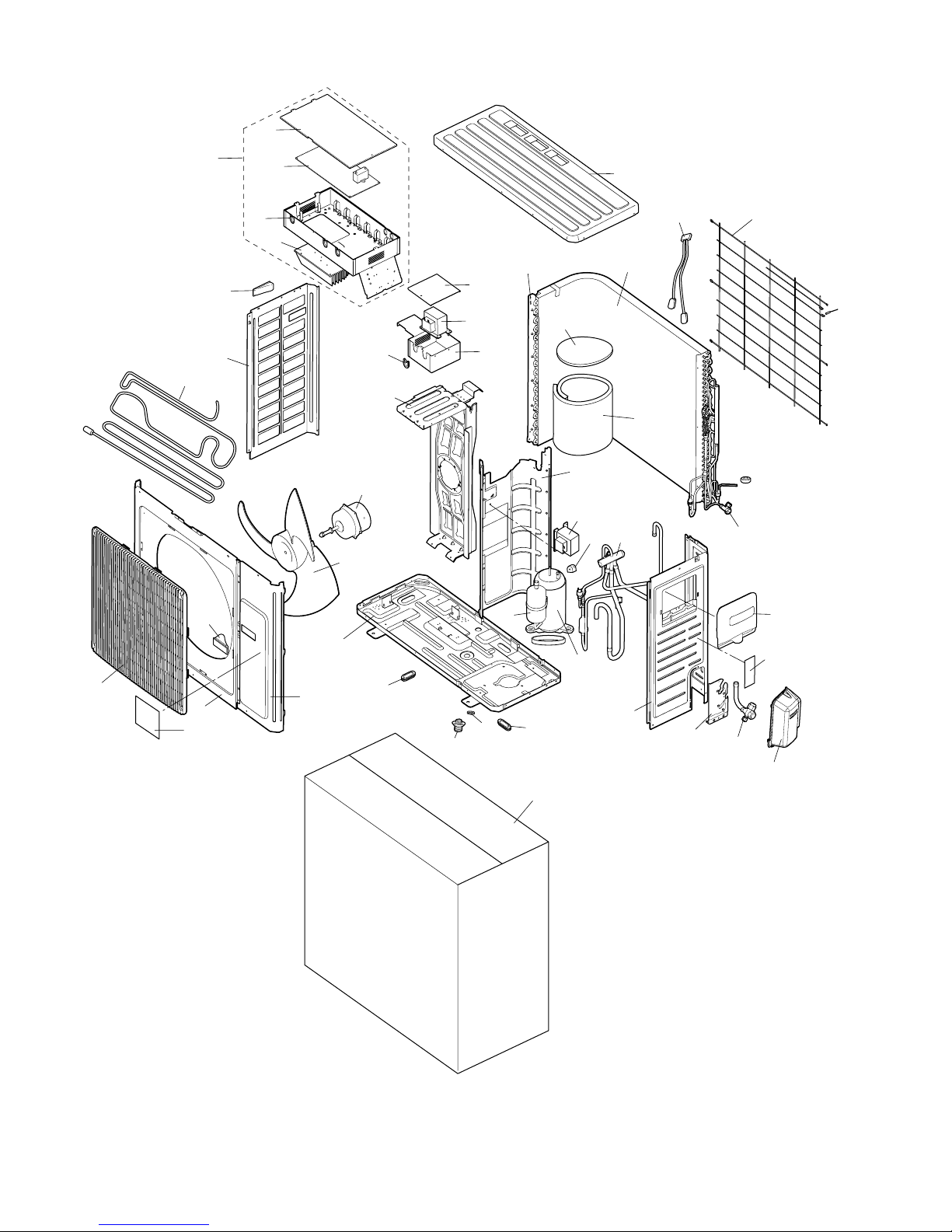
AYX3 6RU
45
14
44
15
16
22
10
38
37
39
35
12
42
42
26
6
4
3
1
40
2
7
5
9
8
11
46
25
24
31
30
29
27
28
21
17
34
18
19
33
22
20
23
32
43
13
[2] OUTDOOR UNIT
4
Page 45
NO. PARTS CODE
PRICE
RANK
NEW
MARK
PAR T
RANK
DESCRIPTION
[2] OUTDOOR UNIT
1 9JX01473050 BB Front Grill
2 9JX0143500401P BD Cabinet
3 9JX01305086P AX Front Side Plate
4 9JX10335014 AX Axial Flow Fan
5 9JX06813401 AC Drainage hole Cap
6 9JX02803026P BK Chassis Sub-assy
7 9JX06123401 AB Drainage Connecter
8 9JX00205275 DE Compressor
9 9JX7651873209 AV Electrical Heater(Compressor)
10 9JX4300040029 AW Magnet Coil
11 9JX03123890 BZ 4-Way Valve Assy
12 9JX0130504402P BA Right Side Plate
13 9JX0171501201P AP Valve Support Sub-Assy
14 9JX22245003 AL Valve Cover
15 9JX07133157 BB Cut off Valve
16 9JX02113109 AX Handle Assy
17 9JX01475013 AS Rear Grill
18 9JX01163491 CT Condenser Assy
19 9JX01175037 AL Condenser Support Plate
20 9JX01802876 BG Motor Support Sub-Assy
21 9JX01255007 BC Top Cover Sub-Assy
22 9JX43130192 BE Reactor
23 9JX76614102 AD Pass Wire Ring Sub-assy
24 9JX26235401 AD Left Handle
25 9JX01305043P AY Left Side Plate
26 9JX1570280205 CF Fan Motor
27 9JX10000100338 CK Electric Box Assy
28 9JX30148360 CH Main Board
29 9JX01425281 AQ Electric Box Cover
30 9JX01413174 AV Electric Box 1
31 9JX49013046 BD Radiator
32 9JX01425279 AG Electric Box Cover
33 9JX01413177 AV Electric Inductance Box
34 9JX3900031001 AU
35 9JX01233134 AY Clapboard
37 9JX75015020 AK Soundproof 3
38 9JX7501580202 AR Soundproofing Cotton
39 9JX07133157 BB Cut Off Valve
40 9JX26235401 AD Left Handle
42 9JX7671301802 AF Drainage Hole Cap
43 9JX62229937233 AH Energy Label
44 9JX63229956736 AF Name Label
45 9JX51029945433 AY Carton Box
46 9JX7651000413 BA Electrical Heater (Chassis)
Temp Sensor
AYX36RU
5
Page 46
AYX3 6RU
INDEX
PARTS CODE No.
[ 9 ]
9JX00205275 2-8 DE
9JX01100100191 1-21 CF
9JX01163491 2-18 CT
9JX01175037 2-19 AL
9JX01233134 2-35 AY
9JX01252398 1-23 AV
9JX01255007 2-21 BC
9JX01305043P 2-25 AY
9JX0130504402P 2-12 BA
9JX01305086P 2-3 AX
9JX01413174 2-30 AV
9JX01413177 2-33 AV
9JX01425279 2-32 AG
9JX01425281 2-29 AQ
9JX0143500401P 2-2 BD
9JX01472022 1-56 AN
9JX01472023 1-48 AN
9JX01473050 2-1 BB
9JX01475013 2-17 AS
9JX01592033 1-53 AF
9JX01592034 1-52 AL
9JX0171501201P 2-13 AP
9JX01802876 2-20 BG
9JX02113109 2-16 AX
9JX02803026P 2-6 BK
9JX03123890 2-11 BZ
9JX05212423 1-43 AC
9JX0523001404 1-27 AL
9JX06123401 2-7 AB
9JX06813401 2-5 AC
9JX07133157 2-15 BB
"2-39BB
9JX10000100338 2-27 CK
9JX10000201845 1-36 BR
9JX10335014 2-4 AX
9JX10352039 1-16 AZ
9JX10352040 1-18 AZ
9JX10512166 1-5 AL
9JX10512167 1-6 AL
9JX10512168 1-9 AC
9JX10512169 1-8 AC
9JX10542704 1-7 AC
9JX10562004 1-34 AC
9JX10562005 1-35 AC
9JX10582041 1-33 AC
9JX10582086 1-10 AC
9JX11122106 1-3 AM
9JX1501213401 1-24 BX
9JX1521210701 1-31 AR
9JX1570280205 2-26 CF
9JX20012712-L2 1-1 BE
9JX20022159 1-4 B D
9JX201022502 1-37 AV
9JX201022523 1-54 AF
9JX2011204404S 1-41 AL
9JX20122124 1-28 AF
9JX20182138 1-12 AY
9JX22202928 1-15 BR
9JX22245003 2-14 AL
9JX24212041 1-20 AH
9JX2421204201 1-25 AG
9JX24212120 1-2 AC
9JX242520053 1-13 AC
9JX26112070 1-32 AC
9JX26112071 1-26 AF
9JX26112158 1-11 AC
9JX26112324 1-30 AF
9JX26112325 1-29 AC
9JX26152028 1-17 AG
9JX26235401 2-24 AD
"2-40AD
9JX30138000192 1-39 BM
9JX30148360 2-28 CH
9JX30510475-L2 1-42 BC
9JX30565124 1-40 AX
9JX390000453 1-59 AH
9JX390000592 1-50 AL
9JX3900031001 2-34 AU
9JX4001024503 1-55 AL
PRICE
RANK
NEW
MARK
PAR T
RANK
PARTS CODE No.
9JX4003800101 1-57 AY
9JX4201026902 1-38 AR
9JX4300040029 2-10 AW
9JX43130192 2-22 BE
9JX49010055 1-58 AG
9JX49013046 2-31 BD
9JX51029945432 1-60 AX
9JX51029945433 2-45 AY
9JX62229937233 2-43 AH
9JX63229956735 1-49 AD
9JX63229956736 2-44 AF
9JX66129916746 1-45 AK
9JX66129916747 1-46 AN
9JX66129916748 1-47 AH
9JX66129916749 1-61 AD
9JX71010103 1-51 AB
9JX75015020 2-37 AK
9JX7501580202 2-38 AR
9JX7508003810 1-22 AF
9JX7651000413 2-46 BA
9JX76512203 1-19 AF
9JX7651873209 2-9 AV
9JX76614102 2-23 AD
9JX76712012 1-14 AC
9JX7671301802 2-42 AF
9JXMC207059-L2 1-44 BP
PRICE
RANK
NEW
MARK
PART
RANK
6
 Loading...