

Page 1
TopPage
AE-X15PU
SERVICE MANUAL
SA210AEX15PU/T
SPLIT TYPE
ROOM AIR CONDITIONER
(OUTDOOR UNIT)
MODEL
In the interests of user-safety (Required by safety regulations in some countries) the set
should be restored to its original condition and only parts identical to those specified should
be used.
CONTENTS
CHAPTER 1. SPECIFICATION
[1] SPECIFICATION............................................ 1-1
[2] EXTERNAL DIMENSION............................... 1-2
........ 1-2[3] WIRING DIAGRM ..................................
[4] ELECTRICAL PARTS................................... 1-4
CHAPTER 2. ELECTROIC CIRCUIT
[1] BLOCK DIAGRAMS...................................... 2-1
[2] MICROCOMPUTER CONTROL SYSTEM....... 2-2
[3] FUNCTION ................................................... 2-6
CHAPTER 3. FUNCTION AND OPERATION
OF PROTECTIVE PROCEDURES
[1] PROTECTION DEVICE FUNCTIONS
AND OPERATIONS......................................3-1
[2] AIR CONDITIONER OPERATION IN
THERMISTOR ERROR................................3-3
[3] THERMISTOR TEMPERATURE CHARACT-
ERISTICS......................................................3-5
[4] HOW TO OPERATE THE OUTDOOR
UNIT INDEPENDENTLY...............................3-5
[5] GENERAL TROUBLESHOOTING
CHART..........................................................3-6
AE-X15PU
AE-X18PU
AE-X24PU
[6] MALF
METHOD.....................................................3-8
[7] OUTDOOR UNIT CHECK METHOD...........3-9
[8] TROUBLESHOOTING GUIDE....................3-12
[9] CHART........................................................3-13
CHAPT
[1] SCHEMATIC DIAGRAM...............................4-1
[2] STANDARD CONDITION.............................4-1
[3] CURRENT OF HEAT CONTROLLER..........4-1
[4] TEMPERATURE AT EACH PART A
PRESSURE IN 3-WAY VALVE.....................4-1
[5] FLOW CHART OF REFRIGERANT
CYCLE...........................................................4-3
[6] CHARACTERISTIC OF COOLING AND
HEATING OPERATION ...............................4-3
CHAPTER 5. DISASSEMBLY PROCEDURE
[1] OUTDOOR UNIT..........................................5-1
[2] DISASSEMBLY OF CONTROL BOX........... 5-4
CHAPTER 6. INSTALLATION MANUAL.............6-1
Parts List
UNCTION(PARTS) CHECK
ER 4. REFRIGERATION CYCLE
ND
Parts marked with " " are important for maintaining the safety of the set. Be sure to replace these parts with specified ones for maintaining the
safety and performance of the set.
This document has been published to be used for
after sales service only.
The contents are subject to change without notice.
Page 2
Propeller fan Φ460, 3-wing
13.0 (330)
800
Oil
FV50S ( 350cc )
1 1
AUX3M24LV
CHAPTER 1. SPECIFICATION
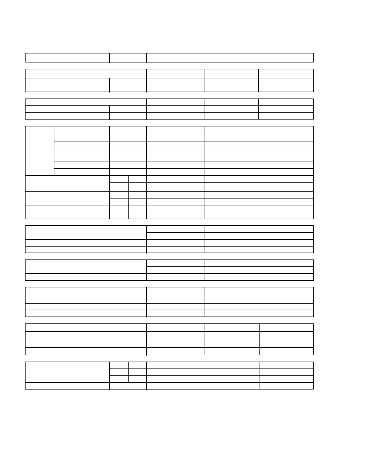
[1] SPECIFICATION
[2] Outdoor
ITEMS
Power supply
Phase
Rated frequency
Reted voltage
System
Indoor units number
Maximum length (per unit)
Maximum height difference
Performance
Capacity (Min.-Max.)
Rated
(Cooling)
Rated
(Heating)
Noise level
Air flow quantity
Fan speed
Compressor system
Compressor
Type
Fan system
Fan motor
Fan
Refrigerant system
Condenser
Refrigerant control
Refrigerant
Refrigerant filling
Connections
Refrigerant coupling
Refrigerant tube size
(A:Gas line,B:Liquid line)
Drain joint
Others
Net dimensions
Net weight
Moisture removal (Liters/h)
Power input
Running current
Capacity (Min.-Max.)
Power input
Running current
INDOOR MODEL AE-X15PU
V
Hz 60
ft (m)
ft (m)
Btu/h 14000(5000 - 14000)
1/h 3.2
W 1120
A 7.5
Btu/h
W
A
Cooling dB(A)
Heating dB(A)
Cooling m3/min
Heating m3/min
Cooling rpm
Heating rpm
Width
Height
Depth
inch(mm)
inch(mm)
inch(mm)
lb (kg)
Single
208/230
65.6 (20)
32.8 (10)
18000(4500 - 20000)
1550
10.0
49
50
42.7
45.8
800
SIAM(13.0cc)SNB130FGBMT
900W
Twin Rotary
CMOTLB537JBEZ
8poles,43W
Louver fin and Grooved tube type
Expansion valve FUJIKOKI Φ1.8
R410A
2.64lb (1200g)
Flare type
A: 1/2" (Flared connection 1/2")
B: 1/4" (Flared connection 1/4")
Connected part O.D.Φ16
33.5 (850)
28.0 (710)
93.7 (42.5)
AE-X18PU
Single
208/230
60
98.4 (30)
49.2 (15)
17000(6000 - 19000)
--
1415 2440
8.0
21600(5500 - 25000) 24000(5500 - 26000)
1920
11.0
52 53
42.3
42.3
820
820 820
SIAM(13.0cc)SNB130FGBMT
900W
FV50S ( 350cc )
Twin Rotary
CMOTLB537JBEZ CMOTLB537JBEZ
8poles,43W 8poles,43W
Propeller fan Φ460, 3-wing
Louver fin and Grooved tube type Louver fin and Grooved tube type
Expansion valve FUJIKOKI Φ2.2 Expansion valve FUJIKOKI Φ2.2
R410A R410A
3.31lb (1500g) 3.31lb (1500g)
Flare type Flare type
A: 1/2" (Flared connection 1/2")
B: 1/4" (Flared connection 1/4")
Connected part O.D.Φ16 Connected part O.D.Φ16
33.5 (850)
28.0 (710)
13.0 (330)
103.6 (47)
AE-X24PU
Single
208/230
60
1
98.4 (30)
49.2 (15)
22000(6000 - 22000)
6.8
12.0
2200
12.5
5453
41.8
44.4
820
SIAM(13.0cc)SNB130FGBMT
900W
FV50S ( 350cc )
Twin Rotary
Propeller fan Φ460, 3-wing
A: 1/2" (Flared connection 1/2")
B: 1/4" (Flared connection 1/4")
33.5 (850)
28.0 (710)
13.0 (330)
103.6 (47)
AE-X15PU
NOTE:Test conditions are based on AHRI 210/240. (Refrigerant piping length [per unit] : 25ft [7.6m])
[TEST CONDITIONS COOLING]
INDOOR DB26.7℃/WB19.4℃
OUTDOOR DB35.0℃/WB --
1 – 1
Page 3
AE-X15PU
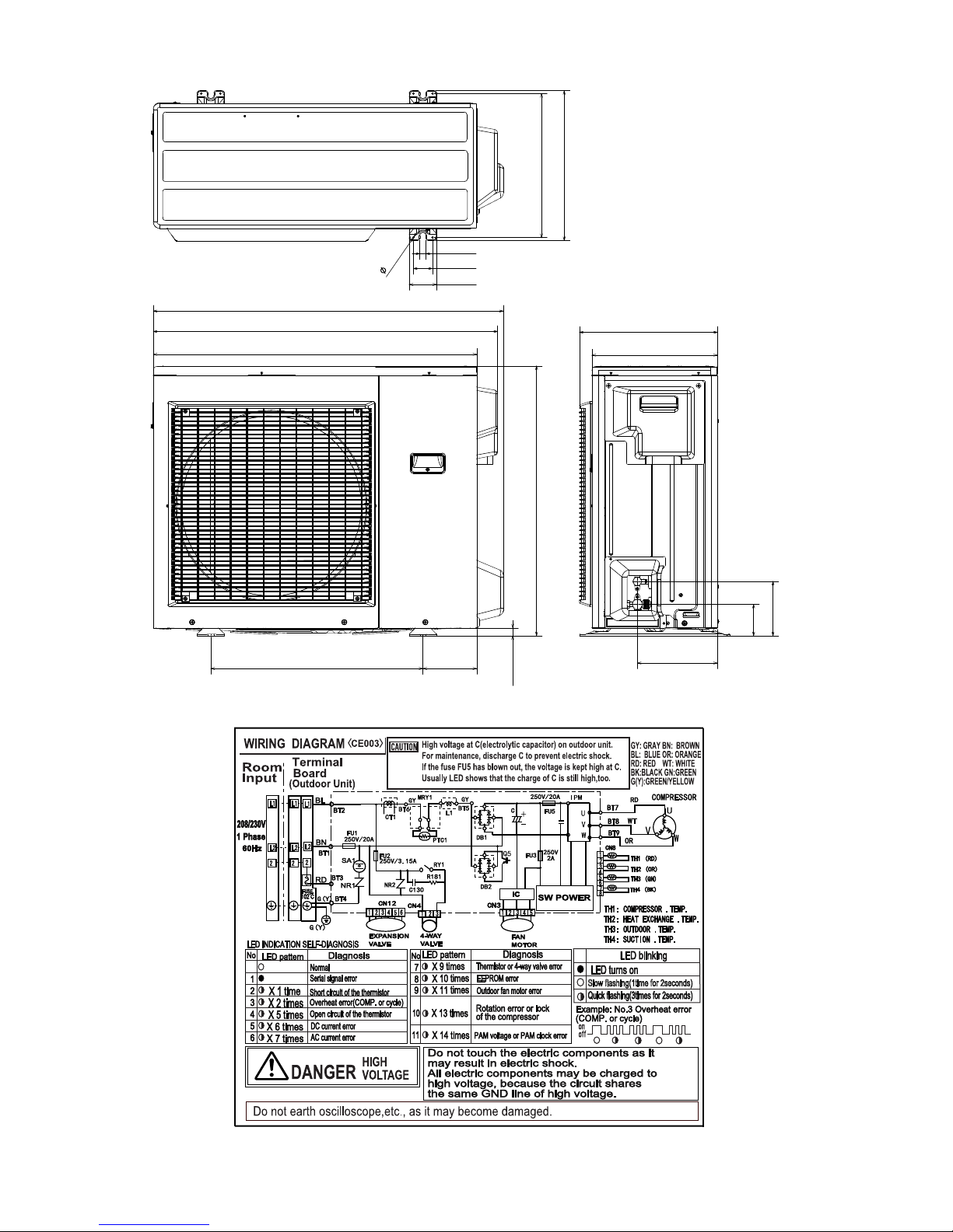
[2] EXTERNAL DIMENSION
Length unit: inch (mm)
33.5 (850)
36.2 (920)
35.6 (905)
0.2 (4.5)
0.6 (16)
2.0 (50)
2.8 (72)
14.9 (379)
15.6 (395)
14.3 (363)
13.0 (330)
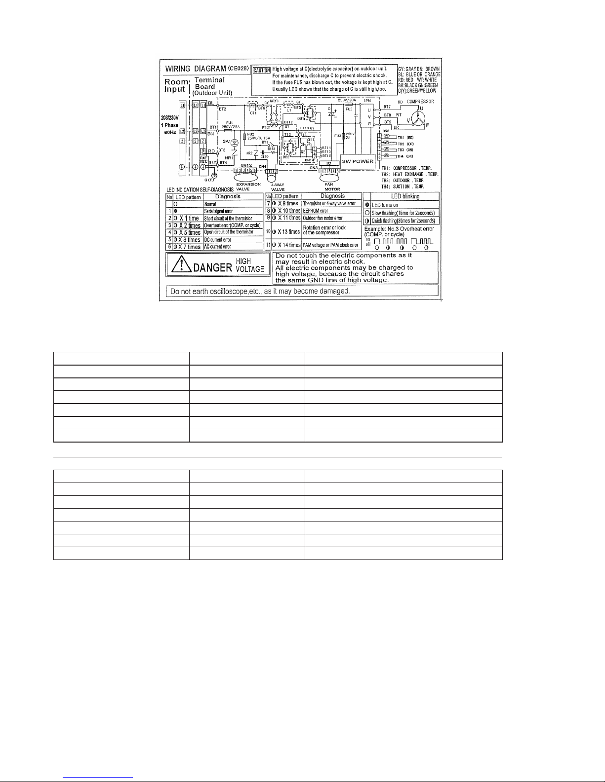
[3] WIRING DIAGRAM
21.9 (557.4)
5.6 (141.3)
28.0 (710)
0.8 (20.7)
8.3 (210.9)
5.6 (143)
3.3 (83)
AE-X15PU/AE-X18PU
1 – 2
Page 4
AE-X15PU
[4] ELECTRICAL PARTS
AE-X15PU / AE-X18PU
Compressor SNB130FGBMT SIAM (13.0 CC) (FCMPRA333JBKZ)
SHA-52FV-D843-2
AE-X24PU
Compressor SNB130FGBMT DC motor (FCMPRA333JBKZ)
SHA-52FV-D843-2
Compressor SNB130FGBMT DC motor (FCMPRA333JBKZ)
Fan motor RDN-280-60-8C DC motor (CMOTLB488JBEZ)
AE-X24PU
skrameRledoMemaN traP
)ZEBJ735BLTOMC( rotom CDrotom naF
)V052 A02( ZZBJ090AG-SFQ-1 uF
)V052 A51.3( ZZBJ870AG-SFQ-2 uF
)V052 A2( ZZBJ770AG-SFQ-3 uF
)V052 A02( 0EBJ090AG-SFQ-5 uF
skrameRledoMemaN traP
)ZEBJ735BLTOMC( rotom CDrotom naF
QFS-GA091JBZZ (25A 250V)-1 uF
)V052 A51.3( ZZBJ870AG-SFQ-2 uF
)V052 A52( ZZBJ770AG-SFQ-3 uF
)V052 A02( 0EBJ090AG-SFQ-5 uF
skrameRledoMemaN traP
)V052 A02( 0EBJ410AG-SFQ-1 uF
)V052 A51.3( ZZBJ870AG-SFQ-2 uF
)V052 A52( ZZBJ770AG-SFQ-3 uF
)V052 A02( 0EBJ910AG-SFQ-5 uF
1 – 3
Page 5
CHAPTER 2.
ELECTROIC CIRCUIT
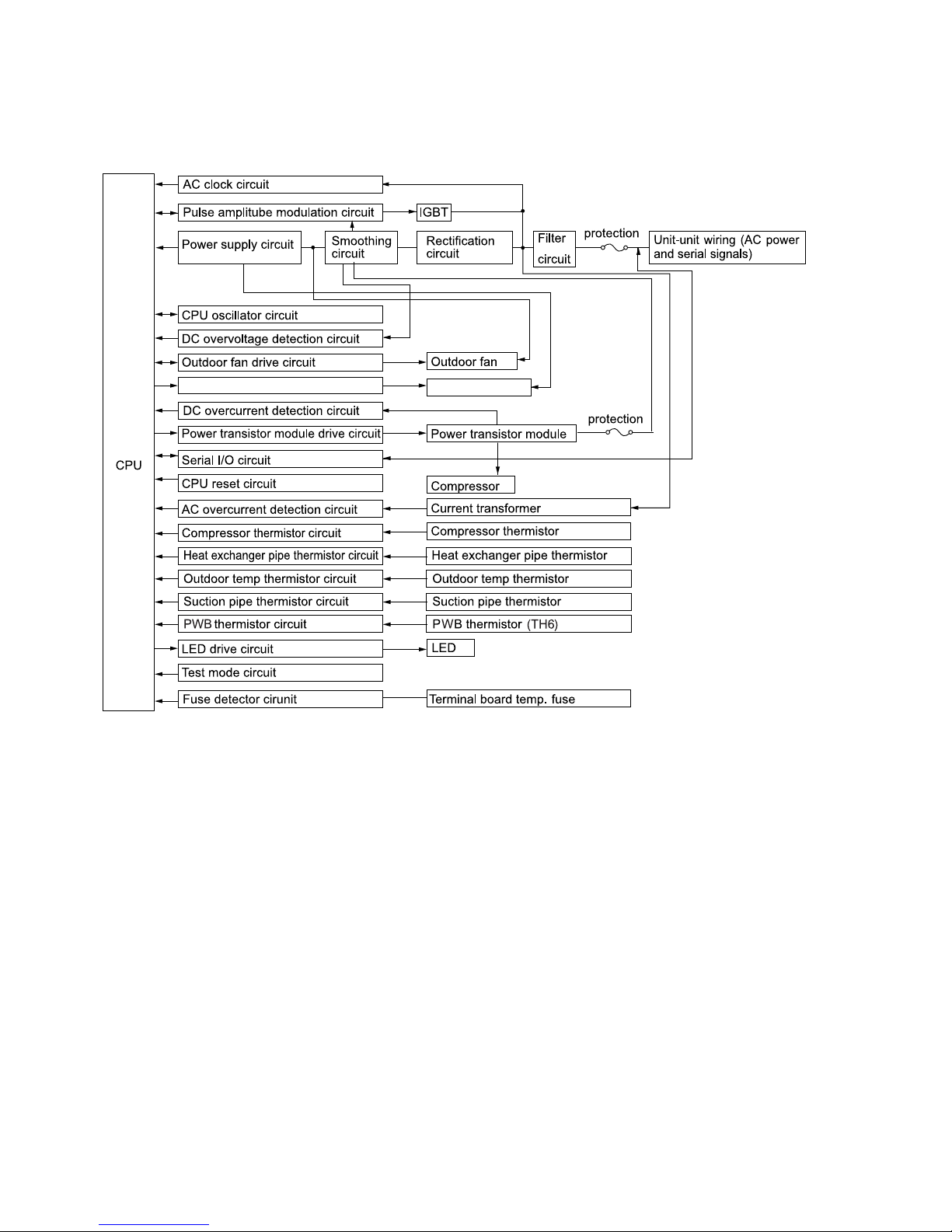
[1] BLOCK DIAGRAMS
1. Outdoor unit
Expansion valve circuit Expansion valve
AE-X15PU
20A(25A for AE-X24PU)
20A
2 – 1
Page 6
AE-X15PU
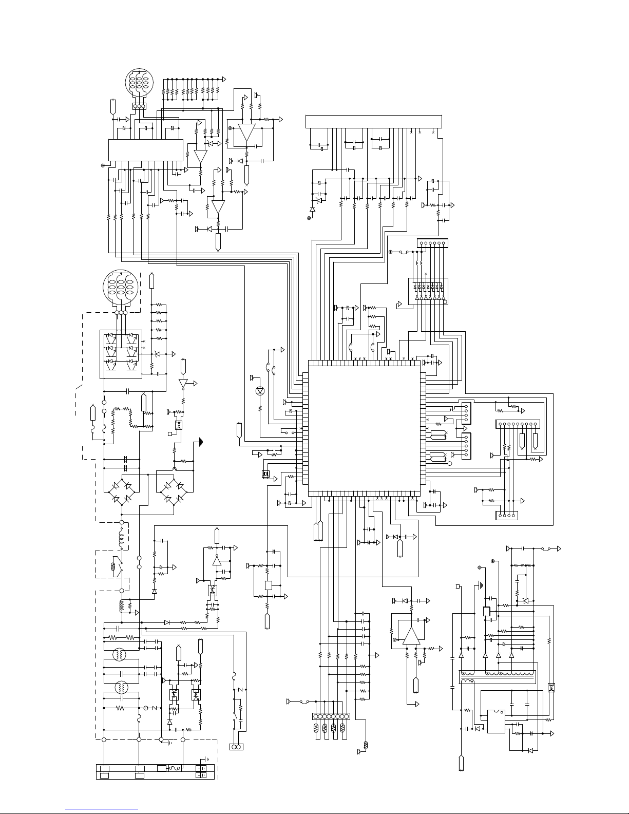
[2] MICROCOMPUTER CONTROL SYSTEM
1-1 Electronic control circuit diagram: AE-X15PU
R199
R223
R197
R171
135
+
50V
C111
9
8
2.2u
C110
20
26
21
22
V
BSV
BSU
S2(V
IS1 U)
IS3(W
50V
C202
1000p
50V
C203
1000p
50V
C204
1000p
5V
100J
R168
R167 100J
Z
R234
R233
R232
R231
R230
18
19
20
N
ZD3
4.7V
CIN
R50
1/4W
1.8KF
15
C122
000P 50V
630V 0.1uF
M
5V
R128
15.4KF
R217
R127
5.4KF
18V-P
1/4W 150J
15V
COMPRESSOR
IPM/A
P
24
JPL1AJPL1B
O
2A
250V
FU3
FU5
23
VCC
IC11
15
C199
100J
R163
82KFX8
250V/20A
O
C29
BSW2VBB
50V
1000p
C200
100J
R164
BT7
23
U
R211 R212
R210
FAN MOTOR
0V
0.1u
630V
+
50V
2.2u
C109
25
50V
1000p
50V
C201
1000p
100J
R165
BT9
BT8
21
22
V
W
C14
R214
R213
R215
R216
- +
420V 750u
C9
- +
420V 750u
C8
CN3
W
100J
R166
DB1
BT5
GRAY
JPL2C
JPL2D
0V
R156
C6
C7
C5
275V 1uF
C4
275V 1uF
250V/20A
BT1
BROWN
L2
L2
R90
D2
SA1
R147
1/10W 10KJ
+
1/10W 1KF
C6A
C7A
250V 4700PX2
250V 0.01uX2
C5A
C4A
250V 0.01uX2
510V
NR1
BT4
GREEN
C97
C79
10V 220uF
R91
1/10W 6.49KF
D13
R104A
250V 4700PX2
5V
PC1
R4
1/10W 3.3KJ
D1
/YELLOW
2
L1
GRAY
PTC1
MRY1/B
GRAY
BT6
CT1
C3
R43
510K 1/4W
L3
C2
L2
C1
R1
BT2
BLUE
L1
L1
Terminal Board
R89
1/4W 1KF
275V 1uF
510K 1/4W
1/2W 1M
FU1
R173
R222
R220
R221
R198
R172
+
50V
7
2.2u
0.1u
C 08
R169
10K
1K
R170
F
10K
0V
F
R182
10K F
R178
R179
10K
U
2+3
13KF
-
GND16GND1VREG13RS10D AG11LW9LV8LU7HW6HV5HU
IC10/C
R177
1
1K
0V
25V
R176
0V
R187
50V
C107
0.01uF
50V
C115
1000p
F
0V
10K
R186
50V
C106
1000p
5V
D20
(R230-R235 1W 140mΩFX5)
(DC Over Current Detect)
0V
C
Q7
0V
R107
1/4W 330Ω
R200
1/10W 1KJ
2
1
PC4
3
LTV817S-C
R110
Q5
R111
1/4W 1KJ
0V-P
DB2
25V 0.1u
R106
1/10W 3.3KJ
0V
5V
PC3
1
C81
50V 0.01uF
(R101A-R101C,R104A-R 04C 1/4W 33K)
R101B
R101C
R101A
R104B
b
a
0V
1000P 50V
C75
R75
1/10W 1.8KJ
R74
R76
1/10W 4.7KJ
1/10W 56KJ
1
23
PC2
1
2 3
LTV817S-C
PC853HXP
R142R141
C13
0.1u 25V
1K 2WX3
R140
C12
BT3
250V 4700P
RED
℃
Fuse
102
0V
R225
R224
R183
ZD6
F
2K
9
IC10/D
R 85
F
10K
0V
4.7V
0V
2KF
R188
0
+
8
1K
A_2
1/4W 2ΩFX12
F
15V
10K
R192
5V
5V
20KF
R 89
C112
50V
1000p
R190
2KF
R193
IC10/B
D21
F
20K
-6+
R191
5V
0V
20KF
2KF
R195
R194
5
11
25V
0.1uF
7
C114
1K
C113
B_2
0V
5V
LED1
2.7K
R73
Q
0V
OSC1
10MHz
D
0V
C83
50V 1000pF
Q6
5V
C82
R80
50V 0.01uF
R105
(Reset)
270
1/10W 22KJ
R78
R77
2 3
R10 C
PC81716
R146
1/10W 100KJ
250V/3.15A
FU2
510V
NR2
R181
1/2W 120J
RY1/B
(Serial Communication)
C130
275V 0.33uF
1
3
CN4
(4-Way Valve Drive)
F
R196
20K
1000pF
50V
PRE-HEAT
JPA
40Hz COOL TEST
JP92
C33
4.7u
+
25V
100K
C32
R79
100J
12
3
C5
C31
270
R
0V
0V
℃
-15 AUTO OFF
5V
+
50V
C98
4.7u
PAD
R92 1K
0V
R129
10K
5V
+
C123
10V 100u
25V
0.1u
0V
25V
0.1u
5V
IPM/B
15V
C124
0V
0.01u 25V
FB3
(Thermister)
2 – 2
VUFB2VP18VVFB3WN
VN1
U
23
13
C49
0.1u 25V
+
C50
10u 25V
C37
25V
00u
+
25V
C38
0.1u
24V
ZD4
D11
WZYVX
PQ1 21
PQ2 22
PQ3 23
PQ 2
PQ5 25
PS0 26
PS1 27
PS2 28
PS3 29
PS 30
PS5 31
VCC 32
VCC 33
VSS 3
C 35
PR0 36
PR1 37
PR2 38
PR3 39
PR 0
PR5 1
MD2 2
MD1 3
MD0
X0 5
X1 6
VSS 7
INITX 8
PA2 9
VSS 50
PC355
PC25
PC153
PC052
VCC51
B_2
A_2
10K
R64 10K
R63
1235678
CN8
TH1
TH2
TH3
Exchange)
(Compressor)
(Heat
12
0.1u
25V
C55
50V
C44
1000pF
100J
100J
R134
C30
100u
+
25V
5V
C93
0.1u
JP2
U
PP 6
PP5 7
VSS 8
VCC 19
PQ0 20
PD060
PC759
PC658
PC557
PC56
10K
10K
R66
R65
TH4
(Suction)
(Out door)
C51
+
C52
R135
10V
10K
R62
0.1u
C41
MAX周波数
PP3 5
PD161
10u
0V
5V
22
25V
25V
50V
PP2 1
AVCC1062
5V
TH6
V
1000pF
100J
PP1 3
AVRH263
7
R136
5V
C126
+
WP
IC1
C125
C64
C69
R68
VN11VP6UN10UP5NC25NC
VWFB
W
2
0.1u
25V
C53
+
25V
C54
10uF
50V
50V
50V
C40
C42
C 3
1000pF
1000pF
00J
100J
R137
R132
FB2
12V
R204
10K
0K
R202
R205
10K
0V
JP1
5V
W/C设定用
M X 6
PM1 8
PM2 9
PM3 0
PP0 2
P91 5
PF0 11
PM0 7
PB671
PB570
PB69
PB368
PB267
PB166
PB065
AVSS106
25V
0.1u
D19
00u
0V
10V
5V
M
5V
C66
C67C68
10KF
15V
0.01u 50V
R123
(C64,C66-C69)
0V
R120
R69
R70
6.8KF
R71
(R61,R68-R71)
R61
(PWB Thermister)
1000p
8
100J
0V
P90
PB772
C87
R124
IC9/B
2KF
R133
IC7
0.01u
D18
P87 3
PA073
100
-2+
9
8
50V
1
C39
50V
MRY1/A
P86 2
PA17
3
2KF
R143
VNC16VNC
1000pF
CN12
VCC 1
VSS75
0V
C90
C89
Z
0V
25V
0.1uF
5V
RY1/A
111213115
C94
5V
C95
VSS100
P8599
P898
P8397
P8296
P8195
P809
PJ793
PJ692
PJ591
PJ90
PJ389
PJ288
PJ187
PJ086
PH285
PH18
PH083
PG582
PG81
PG380
PG279
PG178
PG077
VCC76
5V
000pF
50V
0.1u
25V
R150
5V
0V
17
C47
100uF
+
C48
R45
R46
10V
+
25V
C128
+
C127
0V
0V
R151
20KF
F
20K
FO
1
10V
50V
10K
0V
C45
0.01uF
1KJ
C46
50V
1000p
12356
(Expansion Valve)
1 16923567 10
ULN2004L-D16-T
100u
0V
0.1u
3
2
CN-1
1
5V
10KJ
R122
(PWM Output)
0V
5
3
2
1
F出力
18V-P
R87
C84
1
TR1
8
250V 4700P
2200P
O
35V
+
D1
R17
1/2W 300K
C27
CN-2
PWM Output)
5V
15V
1/4W 5.1K
R22
150u
2
5
1kV
D5
(Debug Output)
5V
(Debug Output)
12V
0V-P
C26
3
C
1
KIA7815
C25
+
10K
C19
D6
16
7
5
800V 1A
C
D
b
5V
a
10V
100u
0V
25V
0.1u
(Inverter Current Detect)
0V
250V 4700P
C85
C105
(Switching Power Supply)
R99
R98
CND
1369578
2
1K
R152
.7K
R154
.7K
R155
CNM
5V
25V
0.1u
R21
2
25V
R82
0.1u
+
35V
150u
C20
680u
D7
13
S8VDD
S
FB
CL
VCC D
IC2
MIP2K30MS
1KJ
1KJ
1K
R153
123
1/4W 2.2K
10K
25V
11
C17
1
2
3
R250R24
C21
470R23
+
D12
1uF 50V
R 6
0V
R
0V
0.1uF 25V
C23
10KF
0.1uF 25V
R88
10K
35V
C24
150u
C18
C 6
261KF
Q
0V
R94
1KJ
(Monitor)
FB1
F10K
R26
IC3
9
2200P 50V
2200P 50V
+
C15
2.2u 50V
D4
(Flash Writer)
0V
470
R15
23
1
PC6
LTV817S-C
15K
R14
0V
Page 7
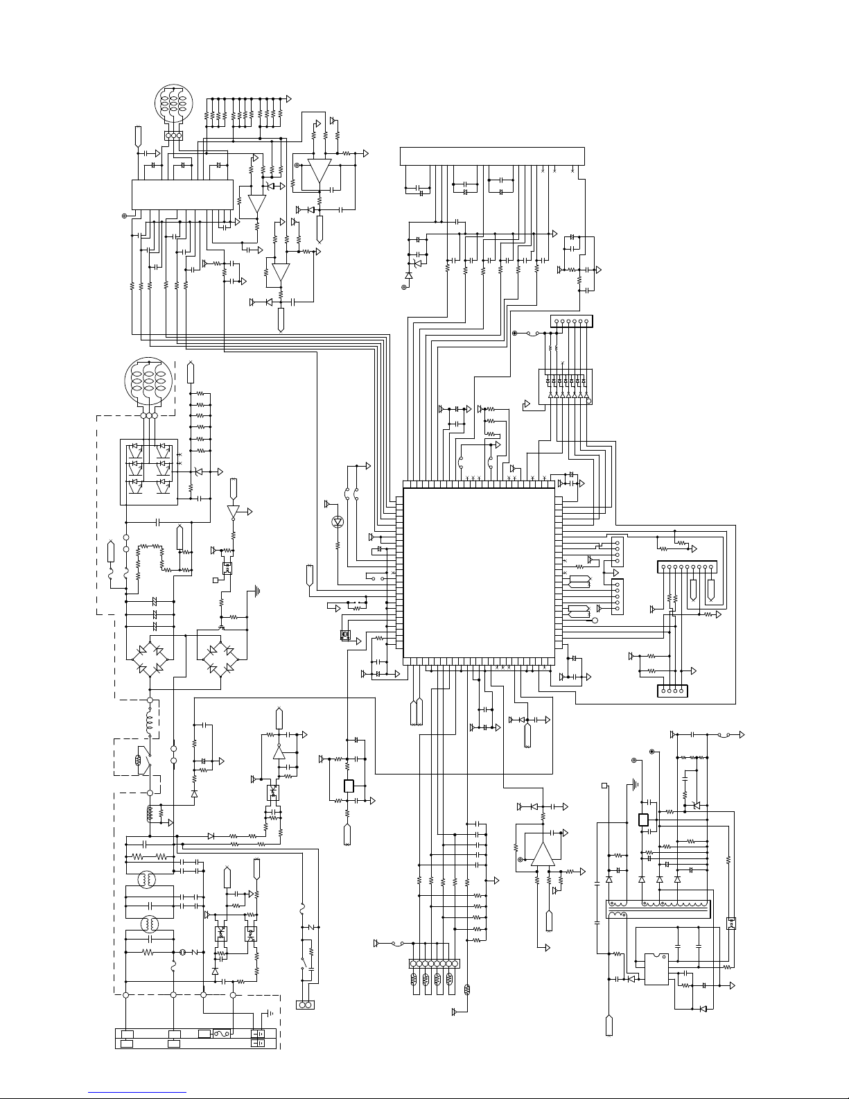
1-2 Electronic control circuit diagram: AE-X18PU
0V
R225
R224
R199
R223
R173
R222
R221
R198
R172
1/4W 2ΩFX12
F
F
10K
10K
0V
F
F
10K F
R178
13KF
IC10/C
R177
0V
0.01uF
C115
0V
1000p
R107
1/4W 330Ω
LTV817S-C
-
1K
1000p
5V
0V
R183
R182
10K
R179
10K
12+13
R192
0V
ZD6
4.7V
0V
5V
1
F
R176
2KF
2K
0V
R189
R188
R187
10+9
50V
F
10K
IC10/D
8
R186
C112
1K
R185
D20
A_2
0V-P
50V
2.2u
17
U
GND6GND1VREG3RS0DIAG11LW9LV8LU7HW6HV5HU
25V
0.1u
C108
50V
C107
10K
1K
R170
50V
C106
(R230-R235 1W 140mΩFX6)
(DC Over Current Detect)
0V
C
Q7
R200
1/10W 1KJ
2
1
PC4
3
R110
R111
1/4W 1KJ
Q5
DB2
D
C83
25V 0.1u
0V
a
1/ 0W 4.7KJ
2 3
C13
C12
R106
1/10W 3.3KJ
Q6
C82
5V
R105
PC3
PC81716
2 3
1
C81
50V 0.01uF
R146
R101B
b
0V
R76
23
R101C
R75
1/10W 1.8KJ
1/10W 56KJ
PC853HXP
R10 C
1/10W 100KJ
(R101A-R101C,R104A-R104C 1/4W 33K)
R101A
R104B
1000P 50V
C75
R74
1
PC2
LTV817S-C
R142R141
0.1u 25
1K 2WX3
R140
(Serial Communication)
BT3
250V 4700P
/YELLOW
GREEN
RED
℃
Fuse
102
CN4
2KF
R193
15V
IC10/B
5V
D21
20KF
F
R190
20K
50V
1000p
Q
0V
50V 1000pF
50V 0.01uF
1/10W 22KJ
250V/3.15A
FU2
NR2
RY1/B
1
3
-6+
R191
510V
R181
C130
5V
0V
20KF
2KF
R195
R194
5
11
25V
0.1uF
7
C114
1K
B_2
0V
5V
LED1
2.7K
R73
OSC1
5V
R80
(Reset)
R78
1/2W 120J
275V 0.33uF
(4-Way Valve Drive)
15V
COMPRESSOR
IPM/A
P
24
JPL1AJPL1B
O
2A
250V
FU3
FU5
510K 1/4W
BT2
BLUE
O
23
VCC
IC11
5
C199
100J
100J
R163
R164
82KFX8
250V/20A
PTC1
C3
R43
L3
L2
C1
R1
L1
L1
0.1u
C29
C109
BSW2VBB
50V
1000p
50V
C200
00J
R165
BT7
BT8
22
23
V
U
R213
R211 R212
R210
BT5
GRAY
L1
GRAY
GRAY
BT6
CT1
C2
FAN MOTOR
CN3
0V
630V
+
50V
2.2u
21
26
25
W
S3(W)
C202
1000p
50V
C201
1000p
100J
R166
BT9
21
W
C14
R214
R215
R217
R216
- +
420V 750u
C10
- +
420V 750u
C9
- +
420V 750u
C8
DB1
JPL2C
MRY1/B
JPL2D
R89
1/4W 1KF
0V
275V 1u
510K 1/4W
R156
275V 1uF
275V 1uF
1/2W 1M
FU1
BT1
BROWN
C110
BSV
50V
1000p
R167 100J
N
C N
L2
L2
135
+
50V
2.2u
22
V
50V
C203
1000p
C204
100J
R168
Z
18
19
20
1/4W
1.8KF
15
630V 0.1uF
M
R147
R90
D2
C6
C7
C5
C5A
C4
C4A
SA1
250V/20A
R171
20
19
S1(U
IS2(V
50V
1000p
5V
R235
R234
R233
R232
R231
R230
ZD3
4.7V
R50
C122
R128
15.4KF
R127
15.4KF
1/10W 10KJ
C79
+
R91
1/ 0W 1KF
250V 4700PX2
C6A
C7A
250V 4700PX2
250V 0.01uX2
250V 0.01uX2
510V
NR1
BT4
/YELLOW
GREEN
2
R197
R220
+
C111
18
BSU
R 69
1000P 50V
5V
18V-P
1/4W 150J
C97
10V 220uF
1/10W 6.49KF
D13
R104A
5V
PC1
1
R4
1/10W 3.3KJ
D1
C113
1000pF
PRE-HEAT
0V
10MHz
100K
270
270
R77
R196
20K
50V
12
IC5
R
F
0V
0V
JPA
℃
- 5 AUTO OFF
5V
+
50V
C98
4.7u
PAD
40Hz COOL TEST
JP92
R92 1K
0V
R129
5V
+
C123
C33
25V
4.7u
+
25V
C32
0.1u
R79
100J
3
0V
25V
C31
0.1u
5V
10K
C124
10V 100u
0.01u 25V
FB3
VUFB2VP18VVFB3WN
IPM/B
C49
0.1u 25V
+
C37
25V
+
100u
25V
C38
0.1u
24V
ZD4
D11
15V
ZWYVX
PQ3 23
PQ 2
PQ5 25
PS0 26
PS1 27
PS2 28
PS3 29
PS 30
PS5 31
VCC 32
VCC 33
VSS 3
C 35
PR0 36
PR1 37
PR2 38
PR3 39
PR 0
PR5 1
MD2 2
MD1 3
MD0
X0 5
X1 6
VSS 7
NITX 8
PA2 9
VSS 50
PC153
PC052
VCC51
0V
B_2
A_2
10K
R63
1235678
CN8
TH1
TH2
(Thermistor)
(Compressor)
(Heat
VN1
U
3
23
C50
10u 25V
100J
5V
U
VCC 19
PQ0 20
PQ1 21
PQ2 22
PC557
PC56
PC355
PC25
0K
R64 10K
R65
TH3
Exchange)
(Outdoor)
2
C51
+
0.1u
25V
C55
50V
C44
1000pF
100J
R134
R135
C30
10V
100u
+
25V
C93
0.1u
JP2
PP 16
PP5 17
VSS 18
PD060
PC759
PC658
10K
10K
R66
TH6
TH4
5V
(Suction)
WP
VWFB
V
7
22
0.1u
C53
0.1u
25V
+
25V
10u
C52
50V
50V
C 3
C41
1000pF
1000pF
100J
100J
R137
R136
R204
5V
R202
0V
R205
JP1
MAX周波数
W/C设定用
M3 10
PP0 12
PP1 13
PP2 1
PP3 15
PF0 11
IC1
PB166
PB065
AVSS 06
AVRH263
AVCC 062
PD161
C126
25V
0.1u
C125
10V
100u
+
5V
C64
C66
C67C68
(C64,C66-C69)
C69
R62
R68
R69
R70
R71
(R61,R68-R71)
R61
(PWB Thermistor)
VN11VP6UN0UP5NC25NC
W
2
25V
25V
10u
C54
50V
50V
C40
C42
1000pF
100J
R132
12V
10K
10K
10K
0V
5V
M1 8
M2 9
M0 7
NMIX 6
PB570
PB69
PB368
PB267
D19
0V
5V
5V
10KF
15V
0.01u 50V
R123
0V
6.8KF
FB2
P91 5
PB671
M
8
R120
1000p
100J
0V
P90
PB772
C87
R124
IC9/B
2KF
R133
IC7
D18
0.01u
-2+
9
P87 3
PA073
100
1
C39
50V
8
P86 2
PA17
50V
2KF
R143
VNC6VNC
0V
0.1uF
5V
1000pF
CN12
MRY1/A
111213115
VCC 1
VSS00
P8599
P898
P8397
P8296
P8195
P809
PJ793
PJ692
PJ591
PJ90
PJ389
PJ288
PJ187
PJ086
PH285
PH18
PH083
PG582
PG81
PG380
PG279
PG178
PG077
VCC76
VSS75
0V
1000pF
50V
C90
0.1u
C89
25V
3
5V
Z
0V
5V
25V
RY1/A
5V
7
C47
+
C48
R45
R46
10V
C94
+
C95
25V
C128
+
C127
0V
0V
F
R151
20K
F
20K
R 50
FO
1
10V
100uF
50V
10K
0V
C45
0.01uF
1KJ
C46
50V
1000p
12356
(Expansion Valve)
1 16923567 10
ULN2004L-D16-T
100u
0V
0.1u
3
2
CN-1
1
5V
10KJ
R122
PWM Output)
0V
5
3
2
1
F出力
18V-P
R87
35V
C84
+
D1
1
TR1
8
250V 4700P
R17
C27
2200P
O
CN-2
(PWM Output)
5V
15V
1/4W 5.1K
R22
150u
2
5
1/2W 300K
1kV
D5
(Debug Output)
5V
(Debug Output)
12V
0V-P
C26
3
C
1
KIA7815
C25
+
10K
C19
D6
16
7
5
800V 1A
C
D
b
5V
a
10V
100u
0V
25V
0.1u
(Inverter Current Detect)
0V
250V 4700P
C85
C105
(Switching Power Supply)
R99
R98
CND
1369578
2
1K
R152
R 54
4.7K
.7K
R155
CNM
5V
25V
0.1u
R21
2
25V
R82
0.1u
+
35V
150u
C20
680u
D7
13
S8VDD
S
FB
CL
VCC D
IC2
MIP2K30MS
1KJ
1KJ
1K
R153
123
1/4W 2.2K
10K
25V
11
C17
1
2
3
R250R24
C21
470R23
+
D12
1uF 50V
R16
0V
R
0V
0.1uF 25V
C23
10KF
0.1uF 25V
R88
10K
50u
35V
C24
C18
C16
261KF
Q
KJ
R94
(Monitor)
F10K
R26
IC3
9
2200P 50V
2200P 50V
+
C15
2.2u 50V
D4
AE-X15PU
(Flash Writer)
0V
0V
FB1
470
R15
23
1
PC6
LTV817S-C
15K
R14
0V
Page 8

AE-X15PU
1-3 Electronic control circuit diagram: AE-X24PU
0V
R225
R224
R199
R223
R173
R222
R220
R221
R198
R172
2ΩF X121/4W
F10K
F10KR182
F10K
0V
R183
R179
10KF
2+3
-
1
1K
R176
0V
50V
1000p
F
10K
5V
0V
123
1/4W 150J
F
0K
0V
R192
ZD6
4.7V
0V
5V
20KF
2KF
2KF
R189
R 88
R 87
10+9
-
IC10/D
8
R186
C112
1K
R185
D20
A_2
P
Q8
5V
R201
1/10W 1KJ
2
1
PC5
3
LTV817S-C
18V-P
BT15
BROWN
BLUE
R113
R112
1/ 0W 1KJ
50V
2.2u
17
R178
U
F13K
GND6GND1VREG3RS0DIAG11LW9LV8LU7HW6HV5HU
IC 0/C
R177
0V
25V
0.1u
C108
50V
R169
C107
0.01uF
10K
C115
1K
0V
R170
50V
C106
1000p
(R230-R235 1W 140mΩF X6)
(DC Over Current Detect)
C
0V
Q7
R107
1/4W 330Ω
1/10W 1KJ
R200
2
1
PC4
3
LTV817S-C
BT14
GRAY
CN14
R110
R111
1/4W 1KJ
Q5
Q11
DB2
(PAM PWB)
D
25V 0.1u
0V
a
1/10W 4.7KJ
1
2 3
C13
C12
R101A
250V 4700P
(R101A-R101C,R 04A-R104C 1/4W 33K)
R104B
C75
1000P 50V
R74
1
PC2
LTV817S-C
1K 2WX3
0.1u 25V
R140
BT3
RED
℃
Fuse
102
C83
50V 1000pF
R106
1/ 0W 3.3KJ
Q6
C82
5V
R105
PC3
PC81716
2 3
1
C81
50V 0.01uF
R146
1/10W 100KJ
R101B
R101C
R 0 C
b
0V
R75
1/10W 1.8KJ
R76
1/10W 56KJ
23
PC853HXP
R142R141
(Serial Communication)
/YELLOW
GREEN
F
2K
R193
15V
IC10/B
5V
D21
20KF
R190
50V
1000p
0V
R109
1/4W 330Ω
Q
BT16
0V-P
0V
50V 0.01uF
1/10W 22KJ
250V/3.15A
FU2
CN4
-6+
R191
RY1/B
1
0V
F2K
R194
5
7
B_2
0V
5V
5V
NR2
3
1K
(Reset)
15V
COMPRESSOR
IPM/A
P
24
O
JPL1B JPL1A
2A
250V
FU3
FU5
510K 1/4W
BT2
BLUE
23
VCC
IC11
5
C199
100J
R163
R164
YELLOW
250V/20A
PTC1
R43
L3
L2
R1
L1
L1
O
C29
BSW2VBB
1000p
50V
C200
00J
BT7
RED
23
U
82KF X8
R211 R212
R210
BT5
GRAY
L1
GRAY
BT6
CT1
C3
C2
C
100J
R165
BT8
WHITE
22
V
R213
GRAY
FAN MOTOR
CN3
0V
0.1u
630V
+
50V
2.2u
C109
26
25
W
S3(W)
50V
1000p
50V
C201
1000p
100J
R166
BT9
ORANGE
21
W
C14
R214
R215
R216
- +
420V 750u
- +
C10
420V 750u
- +
C9
420V 750u
C8
DB1
MRY1/B
R89
1/4W 1KF
275V 1u
510K 1/4W
1/2W 1M
FU1
BT1
135
C110
21
BSV
50V
C202
1000p
R167 100J
N
CIN
M
R217
BT13
BT12
JPL2C
GRAY
JPL2D
0V
R156
C6
C7
C5
275V 1uF
C4
275V 1uF
250V/25A
BROWN
L2
L2
+
50V
2.2u
22
50V
C203
1000p
C204
100J
R168
Z
18
19
20
1/4W
1.8KF
15
630V 0.1uF
GRAY
T13
GRAY
R147
R90
D2
SA1
R171
20
19
V
S1(U
S2(V
50V
1000p
5V
R235
R234
R233
R232
R231
R230
ZD3
4.7V
R50
C122
R128
15.4KF
R127
15.4KF
T12
1/10W 10KJ
C79
+
R91
1/10W 1KF
C6A
C7A
250V 4700PX2
250V 0.01uX2
C5A
C4A
250V 0.01uX2
510V
NR1
BT4
/YELLOW
GREEN
2
R197
+
C111
18
BSU
1000P 50V
5V
18V-P
1/4W 150J
C97
10V 220uF
1/10W 6.49KF
D13
R104A
250V 4700PX2
5V
PC1
R4
1/10W 3.3KJ
D1
5V
F20K
F
R196
20K
R195
11
25V
0.1uF
C114
000pF
C113
50V
℃
PRE-HEAT
JPA
- 5 AUTO OFF
LED1
5V
2.7K
C98
4.7u
R73
0Hz COOL TEST
PAD
JP92
0V
0V
OSC1
10MHz
5V
C33
25V
4.7u
+
25V
R80
100K
C32
0.1u
R79
100J
12
3
IC5
270
R78
C31
25V
0.1u
270
R77
R
510V
R181
1/2W 120J
C130
275V 0.33uF
(4-Way Valve Drive)
0V
IPM/B
D8
R48
R162R161
R47
1/4W
33 X4
15V
VUFB2VP18VVFB3WN
VN1
U
3
23
C49
0.1u 25V
+
C50
10u 25V
C37
25V
+
100u
25V
C38
0.1u
24V
ZD4
D11
WP
VN11VP6UN0UP5NC25NC
VNC6VNC
VWFB
W
V
2
7
21
22
0.1u
25V
C53
C51
0.1u
25V
+
C52
C55
1000pF
100J
+
D10
25V
10u
25V
C54
10u
0.1u
25V
50V
000pF
50V
C40
50V
000pF
50V
C41
1000pF
100J
R135
C42
C 3
R136
1000p
100J
100J
100J
R137
R132
R133
FB2
12V
D9
50V
C44
100J
R134
9
C39
50V
MRY1/A
1000pF
CN12
7
0V
C47
+
0.1uF
R45
5V
R46
RY1/A
11213115
100uF
25V
10K
FO
1
10V
C48
50V
C45
0.01uF
1KJ
C46
50V
1000p
12356
0V
(Expansion Valve)
IC7
C30
100u
10V
+
5V
25V
5V
0V
C93
0.1u
JP1
0V
Z
PQ 2
PQ5 25
PS0 26
PS1 27
PS2 28
PS3 29
PS 30
PS5 31
VCC 32
VCC 33
VSS 3
+
C 35
50V
PR0 36
PR1 37
PR2 38
PR3 39
PR 0
PR5 1
MD2 2
MD1 3
R92 1K
MD0
X0 5
X1 6
VSS 7
NITX 8
PA2 9
VSS 50
R129
10K
PC052
VCC51
C124
0V
0.01u 25V
+
JP2
YVX
W
PQ3 23
MAX周波数
U
PP0 12
PP1 13
PP2 1
PP3 15
PP 16
PP5 17
VSS 18
VCC 19
PQ0 20
PQ1 21
PQ2 22
PF0 11
IC1
PB065
AVSS106
AVRH263
AVCC1062
PD161
PD060
PC759
PC658
PC557
PC56
PC355
PC25
PC153
C123
10V 100u
B_2
A_2
C126
25V
0.1u
C125
10V
100u
+
5V
0V
C64
C66
C67C68
10K
10K
R64 10K
R65
R63
C69
10K
10K
R66
R62
R68
R69
R70
5V
FB3
1235678
CN8
TH1
(Thermistor)
TH2
TH3
TH4
R71
R61
TH6
5V
Exchange)
(Suction)
(Outdoor)
(Compressor)
(Heat
(PWB Thermistor)
R204
10K
R202
10K
R205
10K
0V
5V
W/C设定用
PM1 8
PM2 9
PM3 10
PM0 7
PB69
PB368
PB267
PB166
0V
5V
5V
10KF
0.01u 50V
R123
(C64,C66-C69)
0V
6.8KF
(R61,R68-R71)
0V
8
1 16923567 10
ULN200 L-D 6-T
10V
C94
100u
+
0V
5V
C95
M X 6
P90
P91 5
PB772
PB671
PB570
D19
C87
M
IC9/B
15V
8
R120
25V
VCC 1
P86 2
P87 3
0.1u
VSS00
P8599
P898
P8397
P8296
P8195
P809
PJ793
PJ692
PJ591
PJ90
PJ389
PJ288
PJ187
PJ086
PH285
PH18
PH083
PG582
PG81
PG380
PG279
PG178
PG077
VCC76
VSS75
PA17
PA073
5V
0V
0.01u
50V
D18
1000pF
50V
0V
C90
R124
100
0.1u
0V
C89
25V
1
-2+
R151
3
2KF
2KF
R143
R150
5V
Z
0V
3
2
1
P
C
D
b
a
C128
10V
100u
+
25V
C127
0.1u
CN-1
(PWM Output)
0V
(Debug Output)
5
3
2
CN-2
1
5V
(PWM Output)
(Debug Output)
F出力
5V
0V
15V
0V-P
18V-P
3
1
KIA7815
R87
250V 4700P
C85
1
TR1
8
C105 250V 4700P
C84
+
D1
2200P
1/4W 5.1K
35V
150u
2
5
R17
1/2W 300K
C27
1kV
16
7
5
D5
(Inverter Current Detect)
0V
20KF
F
20K
800V 1A
(Switching Power Supply)
O
12V
C26
IC
C25
+
C19
D6
CND
5V
CNM
25V
2
25V
35V
D7
S8VDD
S
IC2
R99
1KJ
R98
1369578
2
KR153
K
R152
R154
4.7K
R155
4.7K
123
5V
0.1u
R23 470
R21
1/4W 2.2K
R82
10K
0.1u
+
150u
25V
C20
680u
13
11
C17
1
FB
2
CL
3
VCC D
MIP2K30MS
1KJ
R250R24
C21
R88
D12
1uF 50V
R16
C23
R22
+
C24
C16
261KF
0V
R
R94
0V
(Monitor)
0.1uF 25V
10KF
F10K
R26
0.1uF 25V
IC3
10K
10K
35V
150u
9
C18
2200P 50V
+
C15
D4
Q
0V
1KJ
FB1
2200P 50V
2.2u 50V
R15
PC6
R14
(Flash Writer)
0V
470
23
1
LTV817S-C
5K
0V
2 – 4
Page 9
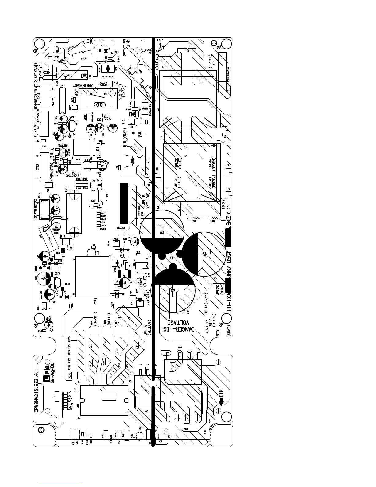
2. Printed wiring board: AE-X15PU
AE-X15PU
This PCB is common for AE-X15PU/X18PU/X24PU, but for AE-X24PU,
there will be a sub-board. Will be released after approval.
2 – 5
Page 10
AE-X15PU
[3] FUNCTION
1. Function
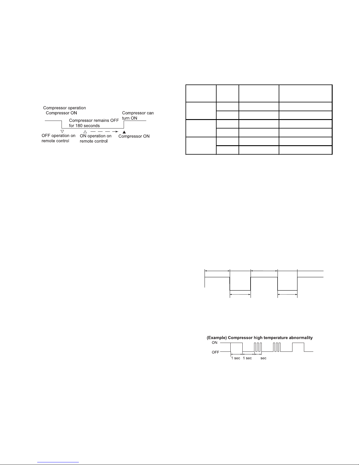
1.1. Restart control
Once the compressor stops operating, it will not restart for 180 seconds to protect the compressor.
Therefore, if the operating compressor is shut down from the remote
control and then turned back on immediately after, the compressor will
restart after a preset delay time.
(The indoor unit will restart operation immediately after the ON switch
is operated on the remote control.)
1.2. Outdoor unit 2-way valve freeze prevention control
If the temperature of the outdoor unit 2-way valve remains below 0°C
for 10 consecutive minutes during cooling or dehumidifying operation,
the compressor operation stops temporarily in order to prevent freezing.
When the temperature of the 2-way valve rises to 10°C or higher after
about 180 seconds, the compressor restarts and resumes normal
operation.
1.3. Outdoor unit overheat prevention control
During cooling operation, if the temperature of the outdoor unit heat
exchanger exceeds the outdoor unit heat exchanger overheat prevention temperature (about 55°C), the operating frequency is decreased
by about 4 to 15 Hz. Then, this operation is repeated every 60 seconds until the temperature of the outdoor unit heat exchanger drops to
about 54
Once the temperature of the outdoor unit
about 54°C or lower, the operating frequency is increased by about 4
to 10 Hz every 60 seconds until the normal operation condition
resumes.
If the temperature of the outdoor unit heat exchanger exceeds the outdoor unit heat exchanger overheat protection temperature for (120
sec. : outdoor temperature ≥ 40°C, 60 sec : outdoor temperature <
40°C) at minimum operating frequency, the compressor stops operat-
ing and then restarts after about 180 seconds, and the above mentioned control is repeated.
°C or lower.
heat exchanger drops to
1.4. Compressor overheat prevention control
If the temperature of the compressor exceeds the compressor overheat prevention temperature (110°C), the operation frequency is
decreased by about 4 to 10 Hz. Then, this operation is repeated every
60
seconds until the temperature of the compressor drops below the
overheat protection temperature (100°C)
Once the temperature of the compressor drops below the overheat
protection temperature, the operating frequency is increased by about
4 to 10 Hz every 60 seconds until the normal operation condition
resumes.
If the temperature of the compressor exceeds the overheat protection
temperature (for 120 seconds in cooling operation or 60 seconds in
heating operation) at minimum operating frequency, the compressor
stops operating and then restarts after about 180 seconds, and the
above mentioned control is repeated.
.
1.5. Peak control
If the current flowing in the air conditioner exceeds the peak control
current (see the table below), the operation frequency is decreased
until the current value drops below the peak control current regardless
of the frequency control demand issued from the indoor unit based on
the room temperature.
Model Mode
AE-X15PU
AE-X18PU
AE-X24PU
Peak Control
Current(A)
Cooling 7.6 0
Heating 9.5 -1.5
Cooling 7.7 0
Heating 10.3 -1.8
Cooling 11.8 0
Heating 12.0 -1.9
Overload Current
Compensation(A)
1.6. Outdoor unit fan delay control
The compressor stops immediately after cooling, dehumidifying or
heating operation is shut down, but the outdoor unit fan continues
operation for 50 seconds before it stops.
1.7. Defrosting
1.7.1 Reverse defrosting
The defrost operation starts when the compressor operating time
exceeds 10 minutes during heating operation, as shown below, and
the outside air temperature and the outdoor unit heat exchanger temperature
the indoor unit fan stops. The defrost operation stops when the outdoor unit heat exchanger temperature rises to about 15°C or higher or
the defrosting time exceeds 9 minutes.
1.8.
If a malfunction occurs, LED1 on the outdoor unit flashes in 0.2-seco
When reading the result of self-diagnosis, you shall combine it with indoor
unit indication in order to get a correct conclusion.
For details, please refer to the troubleshooting section.
meet certain conditions. When the defrost operation starts,
10 min or more 10 min or more 10 min or more
Start of
heating
operation
Defrosting
Max. 9min
Defrosting
Max. 9min
Self-diagnostic malfunction code display of Outdoor unit
nd intervals as shown below.
0 5
2 – 6
Page 11
AE-X15PU
1.9. AUTOMATIC AIR CONDITIONING
In the AUTO mode, the unit will automatically select COOL or HEAT
mode by comparing the room temperature and your desired temperature.
The unit will automatically switch between HEAT and COOL mode to
keep the desired temperature.
COANDA and MULTI SPACE button will be inactivated during AUTO
mode.
Modes and Temperature Settings
the figures in ( ) are temperature settings
During operation, if the outdoor temperature changes, the temperature
settings will automatically slide as shown in the chart.
2. Outline of PAM circuit
1.10. INACTIVATE 5°F(-15°C) AUTO STOP FUNCTION
During the heating operation, the unit will automatically stop when
the outdoor temperature drops below 5°F(-15°C) to prevent the
outdoor unit from the damage caused by the freezing of the drained
water. The unit will stop its operation for 4 hour and then resume
the operation when the outdoor temperature rises above 7°F(-13.9°C).
If the customer do not want to use this function, this function can be
inactivated by cutting JPA on outdoor PWB.
1. Power off.
2. Cut the JPA
cut JPA
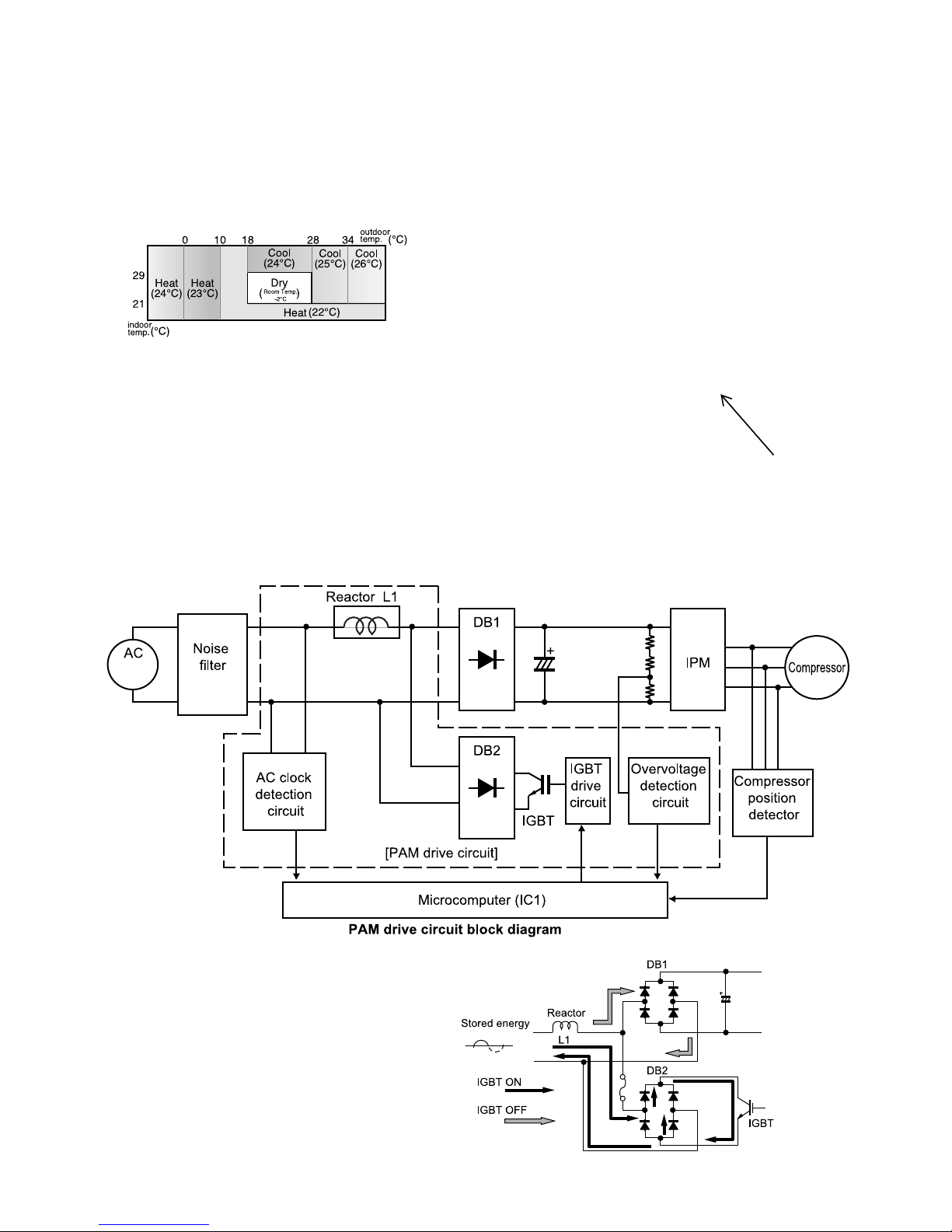
2.1. PAM (Pulse Amplitude Modulation)
The PAM circuit varies the compressor drive voltage and controls the rotation speed of the compressor.
The IGBT shown in the block diagram charges the energy (electromotive force) generated by the reactor to the electrolytic capacitor for the inverter
by turning ON and OFF.
208 or
230V
When the IGBT is ON, an electric current flows to the IGBT via
the reactor (L1) and diode bridge (DB2).
When the IGBT turns OFF, the energy stored while the IGBT
was ON is charged to the voltage capacitor via the diode
bridge (DB1).
As such, by varying the ON/OFF duty of the IGBT, the output
voltage is varied.
2 – 7
Page 12
AE-X15PU
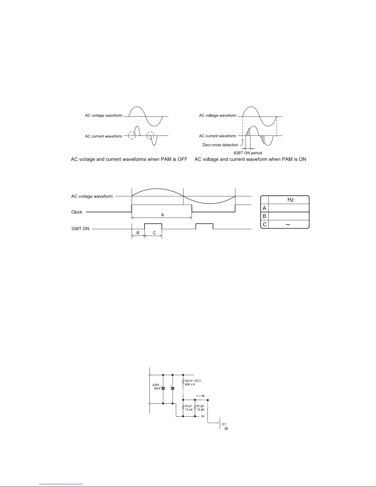
2.2. High power factor control circuit
This circuit brings the operating current waveform closer to the waveform of commercial power supply voltage to maintain a high power factor.
Because of the capacitor input, when the PAM circuit is OFF, the phase of the current waveform deviates from the voltage waveform as shown below.
To prevent this deviation, a current is supplied during the periods indicated by "O" in the diagram.
To determine the length of period to supply a current, the zero-cross timing of the AC input voltage is input to the microcomputer via the clock circuit.
The power source frequency is also determined at the same time.
The IGBT turns ON after the time length determined by the zero-cross point to supply a current to the IGBT via the reactor.
This brings the current waveform closer to the voltage waveform in phase.
As descr bed above, the ON/OFF operation of the IGBT controls the increase/decrease of the compressor power supply voltage (DC voltage) to
improve the compressor efficiency and maintain a high power factor by keeping the current phase closer to that of the supply voltage.
2.2.1 Detailed explanation of PAM drive circuit sequence
60
about 9 mS
1300uS
0.004
1.7ms
2.2.2 AC clock (zero-cross) judgment
• The clock circuit determines the time from one rising point of the clock waveform to the next rising point.
The detected clock waveform is used to judge the power source frequency (60Hz).
• The zero-cross of the AC voltage is judged as the rising of the clock waveform, as shown in the diagram above.
2.2.3 IGBT ON start time (delay time B)
• Based on the zero-cross of the AC voltage, the IGBT turns ON after a delay time set according to the power source frequency.
2.2.4 IGBT ON time (C)
• After the above delay time, the IGBT turns ON to supply a current to the reactor.
• The ON time of the IGBT determines the amount of energy (level of DC voltage rise) supplied to the reactor.
DC voltage level in each operation mode (varies depending on external load conditions)
– Cooling operation --- 220 to 290 V
– Heating operation --- 260 to 290 V
2.3. PAM protection circuit
To prevent excessive voltage of PAM output from damaging the IPM and electrolytic capacitor as well as the control printed wiring board (PWB), this
circuit monitors the PAM output voltage and turns off the PAM control signal and PAM drive immediately when an abnormal voltage output is gener-
ted. At the same time, it shuts off the compressor operation.
a
The protection voltage level is as follows.
C9
C8
7
2 – 8
Page 13

AE-X15PU
2.3.1 Details of troubleshooting procedure for PAM
1) PAM shutdown due to error
1) When the DC voltage detection circuit sends a signal exceeding the specified voltage to the microcomputer
DC voltage of 400 V or higher (detection circuit input voltage of about 4.6 V or higher) [IC1 69 pin]
– When an error is detected
• PAM IGBT turns OFF.
• Compressor turns OFF.
• All units shut down completely when the error occurs four times.
2) When the outdoor unit clock waveform differs from the specified value immediately before the PAM IGBT turns ON
When there is no clock waveform input
When a clock signal of other than specified power source frequency (60Hz) is input
– When an error is detected
• PAM IGBT does not turn ON.
• Compressor operates normally.
• Complete shutdown does not occur.
2) PAM error indication
In case of error “1)”
– An error signal is sent to the indoor unit as soon as an error is generated.
• Malfunction No. 14-0 is indicated when the error code is called out by the indoor unit's self-diagnosis function.
– The LED on the outdoor unit flashes 14 times when an error is generated.
• The LED continues flashing in the 14-time cycle even after the compressor stops ope
• The LED turns off (data is deleted from the memory) when the outdoor unit power is turned off.
In case of error “2)”
– An error signal is sent to the indoor unit as soon as an error is judged.
• Malfunction No. 14-1 is indicated when the error code is called out by the indoor unit's self-diagnosis function.
– The LED on the outdoor unit flashes 14 times when an error is judged.
• The LED on the outdoor unit flashes in normal pattern when the compressor stops operating.
(Compressor OFF or Thermostat OFF from remote control)
* When a user complains that the air conditioner does not provide sufficient cool air or warm air
In addition to conventional error-generating reasons, there is a possibility that the PAM IGBT does not turn ON even if the compressor is operating.
In that case, the DC voltage does not rise even though the compressor is operating, and lowers to the 180-VDC level.
– Check items
• Clock circuit check
• PAM IGBT check
rating.
2 – 9
Page 14
AE-X15PU
3. Explanation of IPM drive circuit
The IPM for compressor drive is made by Mitsubishi Electric.
The power supply for the IPM drive, the shunt resistance for over current detection, etc., are provided outside the IPM (control PWB).
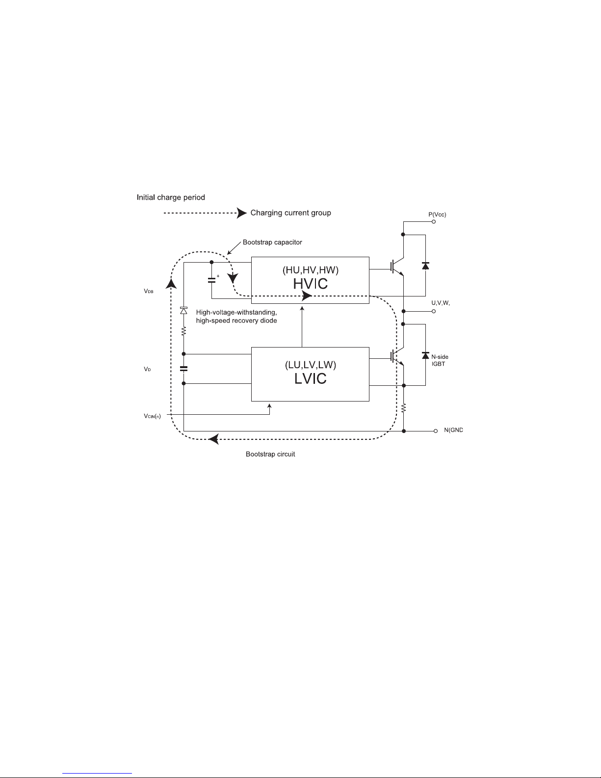
3.1. IPM drive power supply circuit
The power supply for the upper-phase IGBT (HU, HV, HW) drive employs a bootstrap system, and provides power to the upper-phase IC.
The 15-V power supply for the lower-phase IC is provided by the control printed wiring board (PWB).
3.1.1 Brief explanation of bootstrap system (single power drive system)
To supply power to the upper-phase IC, the microcomputer (IC1) turns ON the lower-phase IGBT (LU, LV, LW).
This results in a charging current that flows to the electrolytic capacitor of each upper-phase IC input and charges the bootstrap capacitor with a 15V
current.
The power supply for the subsequent stages is charged while the lower-phase IGBT is ON in ordinary compressor drive c
ontrol.
2 – 10
Page 15

AE-X15PU
3.1.2 DC over current detection circuit
When a current of about 20 A or higher flows through the shunt resistance [AE-X15PU(R230~R234), AE-X18PU/AE-X24PU(R230~R235)] on the
control printed wiring board (PWB), the voltage at this resistance is input to IPM CIN pin (15). Then, the gate voltage of the lower-phase IGBT (LU,
LV, LW) inside the IPM turns OFF to cut off the over current. At the same time, an L output of more than 20μs is generated from IPM from pin (14),
and this results in an L input to over current detection input pin (17) of the microcomputer (IC1) and turns OFF the PWM signal output (IC1 pins (20)
through (25)) to the IGBT gate.
AE-X15PU(R230~R234),
AE-X18PU/AE-X24PU(R230~R235)
2 – 11
Page 16

AE-X15PU
4. 180° energizing control
This is the control system to moderate the speed by the current phase difference for higher efficiency and lower noise of the compressor. The current
phase difference control is the control system paid attention to the interrelation between efficiency and phase gap generated by the applied voltage of
motor and current in the coil of motor as shown in the figure below.
This control is the forced magnetization system independent of the location of rotor, detecting the phase difference between driving voltage phase and
line current phase flowing in motor coil, and controls the modulation rate data to get the phase difference at the best efficiency.
2 – 12
Page 17

AE-X15PU
CHAPTER 3. FUNCTION AND OPERATION OF PROTECTIVE PROCEDURES
[1] PROTECTION DEVICE FUNCTIONS AND OPERATIONS
* These models have following thermistors.
INDOOR UNIT
AE-X15PU, AE-X18PU, AE-X24PU
The errors for the thermistors that are not mentioned above are irrelevant.
These indoor units don’t have power relay.
Description Detection period Reset condition Indoor
1 Indoor unit fan lock Operation stops if there is no
Indoor unit fan rotation speed error
2 2-way valve freeze
prevention
3 Outdoor unit heat
exchanger overheat shutdown
4 Compressor dis-
charge overheat
shutdown
5 Dehumidifying oper-
ation temporary
stop
6 DC over current
error
7 AC over current
error
8 AC over current
error in compressor
OFF status
9 AC maximum cur-
rent error
10 AC current defi-
ciency error
input of rotation pulse signal from
indoor unit fan motor for 1 minute.
Operation stops if rotation pulse
signal from indoor unit fan indicates abnormally low speed
(about 300 rpm or slower).
Compressor stops if temperature
of outdoor unit 2-way valve
remains below 0℃ for 10 continuous minutes during cooling or
dehumidifying operation.
Operation frequency lowers if outdoor unit heat exchanger temperature exceeds about 55℃ during
cooling operation.
Compressor stop
heat exchanger temperature
exceeds about 55℃
onds at minimum frequency.
Operating frequency lowers if
temperature of compressor
chamber thermistor (TH1) falls
below about 110℃.
Compressor stops if temperature
of compressor chamber thermistor (TH1) remains at about
110℃ (for 120 seconds in cooling
operation, or 60 seconds in heating operation) at minimum frequency.
Compressor stops if outside air
temperature thermistor is lower
than about 16℃ during dehumidifying operation.
Compressor stops if electric cur-
about 20 A or higher flows
rent of
in IPM.
Operating frequency lowers if
compressor AC current exceeds
peak control current value. Compressor stops if compressor AC
current exceeds peak control current value at minimum frequency.
Indoor and outdoor units stop if
AC current exceeds about 3 A
while compressor is in non-operation status.
Compressor stops if compressor
AC current exceeds 17 A.
Compressor stops if operating
frequency is 50 Hz o
compressor AC current is about
2.0 A or lower.
s if outdoor unit
for 120 sec-
r higher and
When indoor unit fan
is in operation
When indoor unit fan
is in operation
When in cooling or
dehumidifying operation
When in cooling or
dehumidifying operation
When compressor is
in operation
When in dehumidifying operation
When compressor is
in operation
When compressor is
in operation
When compressor is
in non-operation
When compressor is
in operation
When compressor i
in operation
TH1, TH2, TH3, TH4, TH6
unit
error
display
Operation OFF or ON I2 Yes None
Operation OFF or ON I2 Yes None
Automatic reset when
temperature of 2-way
valve rises above
10℃ .
Automatic reset after
safety period (180
sec).
Automatic reset after
safety period (180
sec).
Automatic reset when
outside air temperature rises above
16℃.
Operation OFF or ON YesI1 Yes
Operation OFF or ON YesI1 Yes Yes
Replacement of
defective parts such
as IPM
Operation OFF or ON Yes I1 Yes Yes
s
Operation OFF or ON Yes I1 Yes Yes
None Yes Yes
None Yes Yes
None Yes Yes
None Yes Yes
YesI2 Yes Yes
result display
Indoor
unit
Outdoor
Yes
sisongaid-fleSnoitarepOnoitcnuF
unit
3 – 1
Page 18

AE-X15PU
F
Description Detection period Reset condition Indoor
11 Thermistor installa-
tion error or 4-way
valve error
12 Compressor high
temperature error
13 Outdoor unit heat
exchanger thermistor short-circuit
error
14 Outdoor unit outside
air temperature
thermistor short-circuit error
15 Outdoor unit suction
thermistor short-circuit error
16 Outdoor unit 2-way
valve thermistor
short-circuit error
17 Outdoor unit heat
exchanger thermistor open-circuit
error
18 Outdoor unit outside
air temperature
thermistor open-cir-
error
cuit
19 Outdoor unit suction
thermistor open-circuit error
20 Outdoor unit 2-way
valve thermistor
open-circuit error
21 Outdoor unit dis-
charge thermistor
open-circuit error
22 Serial signal error Power relay turns OFF if indoor
23 Compressor star-
tup error
24 Compressor rota-
tion error (at 120°
energizing)
25 Outdoor unit DC fan
error
26 PAM over voltage
error
Compressor stops if high and low
values of temperatures detected
by outdoor unit heat exchanger
thermistor (TH2) and 2-way valve
thermistor (TH5) do not match
operating cycle.
Compressor stops if compressor
chamber thermistor (TH1)
exceeds about 114℃
is short-circuit in TH1.
Compressor stops if there is
short-circuit in outdoor unit heat
exchanger thermistor (TH2).
Compressor stops if there is
short-circuit in outdoor unit outside air temperature thermistor
(TH3).
Compressor stops if there is
short-circuit in outdoor unit suction thermistor (TH4).
Compressor stops if there is
short-circuit in outdoor unit 2-way
valve thermistor (TH5).
Compressor stops if there is
open-circuit in outdoor unit heat
exchanger thermistor (TH2).
Compressor stops if there is
open-circuit in outdoor unit outside air temperature thermist
(TH3).
Compressor stops if there is
open-circuit in outdoor unit suction thermistor (TH4).
Compressor stops if there is
open-circuit in outdoor unit 2-way
valve thermistor (TH5).
Compressor stops if there is
open-circuit in outdoor unit discharge thermistor (TH1).
unit cannot receive serial signal
from outdoor unit for
Compressor stops if outdoor unit
cannot receive serial signal from
indoor unit for 30 seconds.
Compressor stops if compressor
fails to start up.
Compressor stops if there is no
input of position detection signal
from compressor or input is
abnormal.
Operation stops if there is no
input of rotation pulse signal from
outdoor unit fan motor for 30 seconds.
Compressor stops if DC voltage is
350 V or higher.
, or if there
or
8 minutes.
result display
Indoor
unit
error
display
3 minutes after compressor startup
When in operation Operation OFF or ON YesI1 Yes Yes
At compressor startup
At compressor startup
At compressor startup
At compressor startup
At compressor startup
At compressor startup
At compressor startup
At compressor startup
ressor star-
At comp
tup
When in operation Operation OFF or ON
When in operation Reset after reception
At compressor startup
Compressor operating at 120° energizing
When outdoor unit
fan is in operation
When in operation Operation OFF or ON Yes I1 Yes Yes
Operation OFF or ON Yes I1 Yes Yes
Operation OFF or ON Yes I1 Yes Yes
Opera
tion OFF or ON YesI1 Yes Yes
Operation OFF or ON Yes I1 Yes Yes
Operation OFF or ON Yes I1 Yes Yes
Operation OFF or ON Yes I1 Yes Yes
Operation OFF or ON Yes I1 Yes Yes
Operation OFF or ON Yes I1 Yes Yes
Operation OFF or ON Yes I1 Yes Yes
Operation OFF or ON YesI1 Yes Yes
(Automatic reset
when less than 8 minutes)
None None None
of serial signal
Operation OFF or ON Yes I3 Yes Yes
Operation OFF or ON Yes I3 Yes Yes
Operation OFF or ON Yes I1 Ye
unit
Yes None
s Yes
Outdoor
sisongaid-fleSnoitarepOnoitcnu
unit
3 – 2
Page 19

Description Detection period Reset co
27 PAM clock error When power source frequency
28 Outdoor unit ther-
mal fuse error in the
Terminal board
I1—The outdoor unit restarts four times before the indoor unit error is displayed (complete shutdown).
I2—A single error judgment results in the display of the indoor unit error (complete shutdown).
I3—The outdoor unit restarts eight times before the indoor unit error is displayed (complete shutdown).
cannot be determined (at startup),
or when power source clock cannot be detected for 1 continuous
second (at startup).
Compressor stops if outdoor unit
cannot receive serial signal from
indoor unit for 30 seconds.
At compressor startup, when in operation
When in operation Reset after reception
Compressor continues operation without stopping.
of serial signal
[2] AIR CONDITIONER OPERATION IN THERMISTOR ERROR
* These models have following thermistors.
INDOOR UNIT
AE-X15PU, AE-X18PU, AE-X24PU
The errors for the thermistors that are not mentioned above are irrelevant.
These indoor units don’t have power relay.
TH1, TH2, TH3, TH4, TH6
ndition Indoor
unit
error
display
None Yes Yes
None None None
AE-X15PU
result display
Indoor
unit
sisongaid-fleSnoitarepOnoitcnuF
Outdoor
unit
3 – 3
Page 20

AE-X15PU
1. Outdoor unit
Item Mode Control opera-
Compressor
chamber thermistor (TH1)
Heat exchanger
thermistor (TH2)
Outside air temperature thermistor (TH3)
Suction pipe thermistor (TH4)
2-way valve thermistor (TH5)
Cooling
Dehumidifying
Heating
Cooling
Dehumidifying
Heating Expansion valve
Auto Operation mode
Cooling
Dehumidifying
Heating Rating control
Cooling
Dehumidifying
Heating Expansion valve
Cooling
Dehumidifying
Heating Operation not
Expansion valve
control and compressor protection
Outdoor unit heat
exchanger overheat prevention
control
Defrosting
judgment
Operation not
affected
Defrosting
Expansion valve
control
control
Expansion valve
control
affected
tion
When resistance is low
(temperature
judged higher
than actual)
Compressor
operates, but
room does not
become cool or
warm (expansion
valve is open).
Compressor
operates at low
speed or stops.
Defrosting operation is not activated as needed,
and frost accumulates on outdoor
unit (
expansion
valve is closed).
Cooling mode is
activated even if
room tempera-
ture is low.
Normal operation. Outdoor unit ther-
Defrosting operation is activated
unnecessarily.
Compressor
operates, but
room does not
become cool
(expansion valve
open).
is
Compressor
operates, but
room does not
become warm
(expansion valve
is open).
Frost accumu-
lates on indoor
unit evaporator
and room does
not become cool
(expansion valve
is closed).
Normal operation. Outdoor unit ther-
Short-circuit When resis-
Compressor high
temperature error
indication.
Outdoor unit thermistor short-circuit error
indication.
Outdoor unit thermistor short-circuit error
indication.
Outdoor unit thermistor short-circuit error
indication.
mistor short-circuit error
indication.
Outdoor unit thermistor short-circuit error
indication.
Outdoor unit thermistor short-circuit error
indication.
Outdoor unit thermistor short-circuit error
indication.
Outdoor unit thermistor short-circuit error
indication.
mistor short-circuit error
indication.
tance is high
(temperature
judged lower
than actual)
Layer short-circuit or open-circuit may result in
compressor in
normal operation.
Normal operation. Outdoor unit ther-
Defrosting operation is activated
unnecessarily,
and room does
not become warm
(expansion valve
is open).
Heating mode is
activated even if
room temperature is high.
Normal operation. Outdoor unit ther-
Defrosting operation is not activated, and frost
accumulates on
outdoor unit.
Frost accumulates on evapora
tor inlet section,
and room does
not become cool
(expansion valve
is closed).
Frost accumulates on expansion valve outlet
section, and room
does not become
warm (expansion
valve is closed).
Compressor
operates, but
room does not
become cool
(expansion valve
is open).
Normal operation. Outdoor unit ther-
Open-circuit
Outdoor unit thermistor open-circuit error
indication.
mistor open-circuit error
indication.
Outdoor unit thermistor open-circuit error
indication.
Outdoor unit thermistor open-circuit error
indication.
mistor open-circuit error
indication.
Outdoor unit thermistor open-circuit error
indication.
Outdoor unit ther-
-
mistor open-circuit error
indication.
Outdoor unit thermistor open-circuit error
indication.
Outdoor unit thermistor open-circuit error
indication.
mistor open-circuit error
indication.
3 – 4
Page 21

[3] THERMISTOR TEMPERATURE CHARACTERISTICS
he
1. Outdoor unit thermistor temperature characteristics
To measure the resistance, first remove the connector from the board.
roloCrotsimrehT No. Connector
Compressor thermistor
Heat exchanger pipe thermistor
Outdoor temp. thermistor
Suction temp. thermistor
500K
TH1: compressor thermistor
400K
300K
200K
Resistance ( )
25ºC resistance
45 K
100K
0
-20 0 20 60 80 100 120
Temperature (ºC)
TH1
TH2
TH3
TH4
1 - 2
3 - 4
5 - 6
7 - 8
Connector
(CN8)
3.06K5.78K
4.17K 2 28K
1.72K
Red
Orange
Green
Black
1 8
Tester
AE-X15PU
TH2: Heat exchange thermistor
TH3: Outdoor temp. thermistor
TH4: Suction pipe thermistor
40K
0ºC resistance
30K
Resistance ( )
20K
14.5 K
25ºC resistance
4.431 K
10K
0
-20 0 20 60
40
Temperature (
Connector
CN8
TH2, TH3, TH4
º
C)
1 8
Tester
[4] HOW TO OPERATE THE OUTDOOR UNIT INDEPENDENTLY
1. Cooling in 40 Hz fixed mode
To operate the outdoor unit independently, short-circuit the sections indicated by arrows in the diagram below with an adapter, and apply rated VAC
between (L1) and (L2) on the terminal board of the outdoor unit. This allows the outdoor unit to be operated in cooling mode independently.
(Do not operate the outdoor unit in this condition for an extended period of time.)
Soldering Side
C8
L2
L3
these pads are connected and Power is applied to L1 and L2 on terminal board.
n the outdoor unit operate in "TEST COOL 40Hz" mode.
C9
3 – 5
Page 22

AE-X15PU
[5] GENERAL TROUBLESHOOTING CHART
* These models have following thermistors.
INDOOR UNIT
AE-X15PU, AE-X18PU, AE-X24PU
The errors for the thermistors that are not mentioned above are irrelevant.
These indoor units don’t have power relay.
1. Indoor unit does not turn on
Main cause Inspection method Normal value/condition Remedy
Cracked PWB.
(Cracked pattern)
Open-circuit in FU1 (250 V, 2.5A). Check melting of FU1. There should be no open-circuit. Replace PWB.
Check visually. There should be no cracking in
2. Indoor unit fan does not operate
Main cause Inspection method Normal value/condition Remedy
Open-circuit in heat exchanger
thermistor (TH2) (in heating operation)
Disconnected heat exchanger
thermistor (TH2) (in heating operation)
Measure thermistor resistance
(dismount for check)
Inspect connector on PWB.
Check thermistor ins
dition.
tallation con-
TH1, TH2, TH3, TH4, TH6
PWB or pattern.
Refer to THERMISTOR TEPERATURE CHARACTERISTICS-1
There should be no open-circuit
or faulty contact.
Thermistor should not be disconnected.
Replace PWB.
Replace thermistor.
Replace thermistor.
Install correctly.
3. Indoor unit fan speed does not change
Main cause Inspection method Normal value/condi
Remote control not designed to
allow fan speed change.
Check operation mode. Fan speed should change except
during dehumidifying operation,
ventilation, light dehumidifying
operation, internally normal operation
tion Remedy
4. Remote control signal is not received
Main cause Inspection method Normal value/condition Remedy
Batteries at end of service life. Measure battery voltage. 2.5 V or higher (two batteries in
series connection)
Batteries installed incorrectly. Check battery direction. As indicated on battery compart-
ment.
Lighting fixture is too close, or fluorescent lamp is burning out.
Use Sevick light (Hitachi). Check if Sevick light (Hitachi) is
Operating position/angle is inappropriate.
Open-circuit or short-circuit in wiring of light receiving section.
Defective light receiving unit. Check signal receiving circuit
w condensation on light receiv-
De
.
ing unit
Turn off light and check. Signal should be received when
light is turned off.
Signal may not be received
used.
Operate within range specified in
manual.
Check if wires of light receiving
section are caught.
(measure voltage between terminals 9 and 10 of connector CN7).
Check for water and rust. Signal should be received within
sometimes due to effect of Sevick
light.
Signal should be received within
range specified in manual.
Wires of light receiving section
should not have any damage
caused by pinching.
Tester indicator should move
when signal is received.
range specified in manual.
Explain to user.
Install new batteries.
Install batteries in indicated direction.
Change light position or install
new fluorescent lamp.
Replace light or change position.
Explain appropriate handling to
user.
Replace wires of light receiving
section.
Replace PWB.
Take moisture-proof measure for
lead wire outlet of light receiving
section.
3 – 6
Page 23

5. Louvers do not move
Main cause Inspection method Normal value/condition Remedy
Caught in sliding section. Operate to see if louvers are
caught in place.
Disconnected connector Inspect connectors. Connectors or pins should not be
Contact of solder on PWB
(connector section on PWB)
Check visually. There should not be solder con-
Louvers should operate smoothly. Remove or correct catching sec-
disconnected.
tact.
6. There is noise in TV/radio
Main cause Inspection method Normal value/condition Remedy
Grounding wires not connected
properly.
TV/radio is placed too close to
outdoor unit.
Other than above. Check for radio wave interfer-
Check grounding wire connections.
Check distance between TV/radio
and outdoor unit.
ence.
Grounding wires should be connected properly.
If TV/radio is placed too close, it
may become affected by noise.
7. Malfunction occurs
AE-X15PU
tion.
Install correctly.
Correct contacting section.
Connect grounding wires properly.
Move TV/radio away from outdoor
unit.
Main cause Inspection metho
Malfunction caused by noise. Che
ence.
ck for radio wave interfer-
d Normal value/condition Remedy
8. Compressor does not start
Main cause Inspection method Normal value/condition Remedy
Erroneous inter-unit connection. Check wiring between indoor and
outdoor units.
Dried-up electrolytic capacitor. Check electrolyt le ecalpeR.roticapac ci ectrolytic capacitor.
Blown outdoor unit fuse. Check 20-A fuse. Fuse should not be blown. Replace fuse/diode bridge.
Power supply voltage is too low. Measure power supply voltage
during startup.
Compressor lock. Supply current and touch com-
pressor cover (sound absorbing
material) to check if operation
starts.
Terminal board 1-N: 230 VAC, 60
Hz
Terminal board 2: serial signal
230±10 VAC, 60 Hz Make sure that power supply volt-
Compressor should start normally.
Correct wiring.
.MPI ecalpeR.ytiunitnoc MPI kcehC.MPI degamaD
Replace fuse.
Replace outdoor unit PWB
assembly.
age is 180 V or higher.
Apply external impact to com-
pressor.
Replace compressor.
9. Operation stops after a few minutes and restarts, and this process repeats
Main cause Inspection method Normal value/condition Remedy
Dried-up electrolytic capacitor. Measure 290-VDC line voltage. 250 V or higher. Replace electrolytic capacitor.
Layer short-circuit in expansion
valve coil.
CAUTION:If fuse FU1/FU5 (outdoor unit control circuit board) is blown, be careful of charging voltage in inverter electrolytic capacitor C8, C9.
To discharge stored electricity, unplug the power cord and connect the plug of a soldering iron (230VAC, 30W) between the positive and
negative terminals of inverter electrolytic capacitor C8, C9.
Measure resistance. 46±3Ω in each phase (at 20℃
) Replace coil.
3 – 7
Page 24

AE-X15PU
[6] MALFUNCTION (PARTS) CHECK METHOD
1. Procedure for determining defective outdoor unit IPM/compressor
The following flow chart shows a procedure for locating the cause of a malfunction when the compressor does not start up and a DC overcurrent indication error occurs.
208/
L1 L2
2. Diode bridge check method
Turn off the power and let the inverter electrolytic capacitor (C8, C9) discharge completely. Then use a tester and check continuity.
When using a digital tester, the (+) and (-) tester lead wires in the table must be reversed.
3. Inverter electrolytic capacitor (C8, C9) check method
Turn off the power, let the inverter electrolytic capacitor (C8, C9) discharge completely, and remove the capacitor from the control printed circuit board
(PWB). First, check the case for cracks, deformation and other damages. Then, using a needle-type tester, check co
Determination of normal condition
The tester needle should move on the scale and slowly returns to the original position. The tester needle should move
in the same way when polarities are reversed. (When measurement is taken with the polarities reversed, the tester
needle exceeds the scale range. Therefore, let the capacitor discharge before measurement.)
ntinuity.
3 – 8
Page 25

AE-X15PU
4. IPM check method
Turn off the power, let the large capacity electrolytic capacitor (C8, C9) discharge completely, and dismount the IPM. Then, using a tester, check leak
current between C and E.
When using a digital tester, the (+) and (-) tester lead wires in the table must be reversed.
Needle-type tester Normal resistance value
(-) (+)
P N
U
V
W
Needle-type tester Normal resistance value
(-) (+)
U N ∞
V
W
Values in ( ) are for digital tester.
∞
(several MΩ)
(several MΩ)
[7] OUTDOOR UNIT CHECK METHOD
After repairing the outdoor unit, conduct the following inspection procedures to make sure that it has been repaired completely. Then, operate the
compressor for a final operation check.
1. Checking procedures
No
.
1 Preparation Disconnect compressor cords (white,
orange, red: 3 wires) from compressor terminals, and connect simulated
load (lamp used as load).
Operate air conditioner in cooling or
heating test operation mode.
2 Inverter DC power supply
voltage check
3 IPM circuit check Check that 3 lamps (load) light.
4 Compressor check Measure compressor coil resistance
5 Expansion valve check Measure expansion valve coil resis-
6 Final check Turn off power, and connect compres-
Measure DC voltage between IPM
pins (20) and (24).
Check position detection voltage (+15
V, 5 V) on control PWB.
(fo
r each phase of U, V and W).
Use multi-meter o
ble of displaying two digits right of the
decimal point (0.01Ω).
tance.
sor cords to compressor.
Operate air conditioner.
Measure DC voltage between IPM
pins (20) and (24).
r digital tester capa-
ydemeRnoitidnoc/eulav lamroNdohtem kcehCmetI
.BWP lortnoc ecalpeRCDV 023
Replace diode bridge.
Correct soldered section of Fasten tabs (BT1, BT2, BT5,BT6) on
control PWB and IPM (S, C, R).
(Repair solder cracks.)
Each voltage should be normal.
All 3 lamps (load) should light with
same intensity.
Resistance value at 20℃ --- 0.65Ω Correct connections at compres-
Each phase 46±3Ω (at 20℃) Replace expansion valve.
Compressor should operate normally.
200 VDC or higher.
Replace control PWB.
sor terminals.
Replace compressor.
Replace control PWB.
Replace outdoor unit thermistor.
Replace compressor (in case of
compressor lock).
3 – 9
Page 26

AE-X15PU
2. Troubleshooting of outdoor unit electric components
2
3
3
3 – 10
Page 27

AE-X15PU
3. Caution in checking printed wiring boards (PWB)
3.1. Non-insulated control circuit
The GND terminals of the low-voltage circuits (control circuits for microcomputer and thermistors and drive circuits for expansion valve and relays) on
the control printed wiring board (PWB) are connected to the compressor drive power supply (320-VDC negative terminal). Therefore, exercise utmost
caution to prevent electric shock.
If a measuring instrument used for the test is grounded, its chassis (ground) has the same electric potential as the 0-V probe. Since non-insulated circuits have the following voltage potential difference from the ground, connection of the grounding wire results in a short-circuit between the 0-V line
and the ground, thus allowing an excessive current t
the sheaths of the thermistor lead wires or expansion valve lead wires inside the outdoor unit become damaged due to pinching by the front panel
If
or other metal parts or contacting a pipe, a high voltage can flow and destroy the circuits. To prevent these problems, carefully conduct assembly
work.
L1
208/230V
L2
o flow to the tester to cause damage.
3 – 11
Page 28

AE-X15PU
[8] TROUBLESHOOTING GUIDE
1. Self-Diagnosis Function
1.1. Indoor unit
• To display the self-diagnosis, hold down the AUX button for over 5 seconds on the indoor unit when the indoor unit is not operating.
• The operation lamp (green), timer lamp (orange) and Plasmacluster lamp (blue) flash to indicate the information of malfunction.
• If the power cord is unplugged or the circuit breaker is turned off, the self-diagnosis memory is lost.
AUX
Plasmacluster lamp(Blue)
Operation lamp(Green)
Timer lamp(orange)
<Display of self-diagnosis result>
The operation lamp (green) and the Plasmacluster lamp (blue) flash in synchronization with the timer lamp (orange).
Timer lamp (1 cycle)
1st 2nd 3rd 4th 5th
1-second
ON
1-second
ON
1-second
ON
1-second
ON
1-second
ON
ON
OFF
1-second
OFF
1-second
OFF
1-second
OFF
1.2. Outdoor unit
• The self-diagnosis is indicated the error information by flashing LED1 on the outdoor unit.
• The self-diagnosis of outdoor unit is displayed for sbout 3-10 minutes.Then ,the LED1 returns to normal display.
1-second
OFF
5-second OFF
3 – 12
Page 29

[9] CHART
<INDOOR UNIT> ○:1-second ON / 1-second OFF
AE-X15PU
Problem
symptom
Normal
condition
Indoor and
outdoor units
do not operate.
Indoor and
outdoor units
do not
operate.
Outdoor
unit
indication
(LED1)
Normal
blinking
1-time
2-time
Indoor unit
→
O O O O O Timer (Orange)
O O O O O Timer (Orange)
O Operation (Green)
O O O O O Timer (Orange)
O Operation (Green)
O Plasmacluster (Blue)
O O O O O Timer (Orange)
O Operation (Green)
O Plasmacluster (Blue)
O O O O O Timer (Orange)
O Operation (Green)
O O Plasmacluster (Blue)
O O O O O Timer (Orange)
O Operation (Green)
Lamp Main Sub Main Sub
Operation (Green)
Plasmacluster (Blue)
Plasmacluster (Blue)
Plasmacluster (Blue)
Malfunction
No.*
0 0 Normal
1 0 Outdoor unit
1 Outdoor temperature
2 Suction hermistor
3 Suction hermistor
2 0 Cycle
Content of diagnosis Check point Action
thermistor
short-circuit
temperature
Heat exchanger
thermistor short
circuit error
thermistor short
circuit error
short circuit error
(for unit A, B, C)
short circuit error
Compressor high
temperature error
1) Measure the resistance
of the outdoor unit
thermistors.
2) Check the lead wire
of the outdoor unit
thermistor for torn
sheath and shortcircuit.
3) 1) 2):Normal
1) Check the outdoor unit
air outlet for blockage.
2) Check if the power
supply voltage is AC
230V at full power.
3) Check the pipe
connections for
refrigerant leaks.
4) Measure resistance
of the outdoor unit
compressor thermistor.
5) Check the expansion
valve for proper
opera ion.
1) Replace the outdoor
unit thermistor
assembly.
2) Replace the outdoor
unit thermistor
assembly.
3) Replace the outdoor
unit control PCB
assembly.
1) Ensure unobstructed
outdoor unit air
ou let.
2) Connect power
supply of proper
voltage.
amount of refrigerant.
4) Replace he outdoor
unit compressor
thermistor assembly.
5) Replace he expansion valve coil,
expansion valve or
outdoor unit control
PCB assembly.
Indoor unit
operates.
Outdoor
unit does
not operate
temporarily
Indoor and
outdoor
units do not
operate.
Indoor unit
operates.
Outdoor
unit does
not operate
temporarily.
3-time
O O O O O Timer (Orange) 1 Compressor
O Operation (Green)
O Plasmacluster (Blue)
O O O O O Timer (Orange) 2 Outdoor unit heat
O Operation (Green)
O Plasmacluster (Blue)
O O O O O Timer (Orange) 3 Indoor unit heat
O Operation (Green)
O O Plasmacluster (Blue)
O O O O O Timer (Orange) 4 IPM high
O Operation (Green)
O Plasmacluster (Blue)
O O O O O
O O O O O
Timer (Orange) 5 IPM high
O Operation (Green)
O O Plasmacluster (Blue)
Timer (Orange)
Operation (Green)
O O
Plasmacluster (Blue)
3 0
Dry operation
Heat
operation
3 – 13
discharge overheat.
exchanger overheat.
exchanger overheat.
temperature error
temperature error
Temporary stop
due to dehumidifying opera ion
5℉/-15℃
AUTO OFF
(Temporary stop for cycle
protection)
(Temporary stop for cycle
protection)
(Temporary stop for cycle
protection)
Measure resistance of the
heat-sink hermistor.
Replace the outdoor unit
control PCB assembly.
(Temporary stop for
cycle protection)
Measure the resistance
of outdoor temperature
thermister.
-
-
-
-
-
-
Replace the indoor
unit thermister assembly.
Page 30

AE-X15PU
Problem
symptom
Indoor and
outdoor
units do not
operate.
Indoor and
outdoor
units do not
operate.
Indoor and
outdoor
units do not
operate.
Indoor and
outdoor
units do not
operate.
)
)
)
)
)
)
)
)
)
)
)
)
)
Malfunction
No.*
Content of diagnosis Check point Action
thermistor
open-circuit
DC Current
AC Current
wire check
Outdoor
unit
indication
(LED1)
5-time O O O O O Timer (Orange) 5 0 Outdoor unit
O O O O O Timer (Orange) 1 Outdoor temperature
O O O O O Timer (Orange) 2 Suction thermistor
O O O O O Timer (Orange) 3 Suction thermistor
O O O O O Timer (Orange) 4 Discharge thermistor
O O O O O Timer (Orange) 5 Heat sink thermistor
6-time O O O O O Timer (Orange) 6 0 Outdoor unit
O O O O O Timer (Orange) 1 IPM pin level error Check the IPM is attached
7-time O O O O O Timer (Orange) 7 0 Outdoor unit
O O O O O Timer (Orange) 1 AC current error
O O O O O Timer (Orange) 2 AC maximum current
O O O O O Timer (Orange) 3 AC current
8-time O O O O O Timer (Orange) 8 0 Abnormal
Indoor unit
→
O O Operation (
O O Operation (
O Plasmacluster (Blue)
O O Operation (
O Plasmacluster (Blue)
O O Operation (
O O Plasmacluster (Blue)
O O Operation (
O Plasmacluster (Blue)
O O Operation (
O O Plasmacluster (Blue)
O O Operation (
O O Operation (
O Plasmacluster (Blue)
O O O Operation (
O O O Operation (
O Plasmacluster (Blue)
O O O Operation (
O Plasmacluster (Blue)
O O O Operation (
O O Plasmacluster (Blue)
O Operation (
Lamp Main Sub Main Sub
Green
Plasmacluster (Blue)
Green
Green
Green
Green
Green
Green
Plasmacluster (Blue)
Green
Green
Plasmacluster (Blue)
Green
Green
Green
Green
Plasmacluster (Blue)
Heat exchanger
thermistor open
circuit error
thermistor open
circuit error
open circuit error
open circuit error
open circuit error
open circuit error
DC over current
error
AC over current error 1) Ensure unobstructed air
when OFF
error
Abnormal wire check
error
1) Check connector of
outdoor unit thermistor
for secure installa ion.
2) Measure resistance of
outdoor hermistors
3) Check the lead wires
of hermistors on the
outdoor unit control
PCB for open-circuit.
4) 1) 2) 3):Normal
Go to “DC Over Current Error (6-0 error)”.
correctly to the outdoor unit
IPM PWB.
unit air outlet.
2) Check the outdoor unit
fan motor.
1) IPM con inuity check 1) Replace the outdoor
1) Ensure unobstructed air
unit air outlet.
2) Check the outdoor unit
fan motor.
1) Replace the outdoor unit
control PCB assembly.
amount of refrigerant.
3) Correct refrigerant clogs.
(Stop valve, pipe,
expansion valve)
1) Check the expansion
valve.
2) Are four expansion
valves connected by
mistake.
3) Check the wiring
between units.
1) Correct the installaion
2) Replace the outdoor
unit thermistor
assembly.
3) Replace the outdoor
unit thermistor
assembly.
4) Replace the outdoor
unit control PWB
assembly.
Replace the outdoor
unit IPM PWB
assembly.
1) Ensure unobstructed
outdoor unit air
outlet.
2) Check the outdoor
unit fan motor.
IPM PWB
1) Ensure unobstructed
outdoor unit air
outlet.
2) Check the outdoor
unit fan motor.
1) Replace the outdoor
unit control PCB
assembly.
amount of refrigerant.
3) Correct refrigerant
clogs. (Stop valve,
pipe, expansion
valve)
1) Replace the outdoor
control board
assembly.
2) Reattach
3) Check the wiring
between units.
3 – 14
Page 31

AE-X15PU
Problem
symptom
Indoor and
outdoor
units do not
operate.
Indoor and
outdoor
units do not
operate.
Indoor and
outdoor
units do not
operate.
Outdoor
unit
Indoor unit
Malfunction
No.*
Content of diagnosis Check point Action
indication
(LED1)
Lamp Main Sub Main Sub
0
Green
9
)
Cycle
temperature
9- ime
→
O O O O OOTimer (Orange)
O Operation (
Plasmacluster (Blue)
O O O O O Timer (Orange)
O O Operation (
Green
)
4 Cycle
temperature
O Plasmacluster (Blue)
10-time O O O O O Timer (Orange) 10 0 EEPROM
O O Operation (Green)
error
Plasmacluster (Blue)
O O O O O Timer (Orange) 1 EEPROM (outdoor)
O O Operation (Green)
O Plasmacluster (Blue)
O O O O O Timer (Orange) 10 2 EEPROM
O O Operation (Green)
error
O Plasmacluster (Blue)
11-time O O O O O Timer (Orange) 11 0 Outdoor unit
DC fan
O O O Operation (Green)
Plasmacluster (Blue)
Thermistor
installation error
or 4-way valve
error.
4 way valve error or
Gas leak error
EEPROM (outdoor)
data error
data error
EEPROM (outdoor)
data error
Outdoor unit DC fan
rotation error
1)Check the thermistor (heat
exchanger) and (2way valve) are
installed in correct
positions.
2)Check resistance of
hermistors (heat
exchanger and 2way valve).
3)Check the 4-way
valve for proper
operation.
4)No abnormality
found in above
inspections (1), (2),
(3).
1) Check the unit thermistor
TH2 (exchange) and
TH3 (pipe temperature)
are installed in correct
portions.
2) Check if the refrigerant
volume is abnormally
low.
1)Correct the installa ion.
2)Change he
specified amount
of refrigerant.
3)Replace the 4way valve.
4)Replace the outdoor unit control
PWB assembly.
1) Correct the
installation.
2) Change the
refrigerant.
3) Replace the 4-way
valve.
3) Check the 4-way valve
for proper operation.
-
Replace the outdoor
unit control PWB
assembly.
- Replace the outdoor
unit control PWB
assembly.
1) Check connector CN3
of the outdoor unit DC
fan motor for secure
installation.
2) Check the outdoor unit
fan motor for proper
rotation.
3) Check fuse FUSE5.
4) Outdoor unit control
PWB
1) Correct the installation.
2) Replace the outdoor
unit fan motor.
3) Replace the outdoor
unit control PWB
assembly.
4) Replace the outdoor
unit control PWB
assembly.
O O O O O Timer (Orange) 1 Outdoor unit DC fan
O O O Operation (Green)
O Plasmacluster (Blue)
O O O O O Timer (Orange) 2 Outdoor unit DC fan
O O O Operation (Green)
O Plasmacluster (Blue)
O O O O O Timer (Orange) 3 Detection error of DC
O O O Operation (Green)
O O Plasmacluster (Blue)
O O O O O Timer (Orange) 4 Detection error of
O O O Operation (Green)
O Plasmacluster (Blue)
O O O O O Timer (Orange) 5 Outdoor unit DC fan
O O O Operation (Green)
O O Plasmacluster (Blue)
3 – 15
driver IC error
lock error
fan nega ive rotation
before compressor is
driven
inverter current for
DC fan
open connector error
1) Check if the fan IPM
terminal resistance
values are uniform.
2) Outdoor unit fan motor
continuity check.
1) Check the outdoor unit
fan motor for proper
rotation.
2) 1): Normal
1) Replace the outdoor
unit control PWB
assembly.
2) Replace the outdoor
unit fan.
1) Replace the outdoor
unit control PWB
assembly.
2) Replace the outdoor
unit fan.
(Temporary stop for DC
-
fan circuit protection)
- Replace the outdoor
unit control PWB
assembly.
1) Check connector CN3
of the outdoor unit DC
fan motor for secure
installation.
2) No abnormality found in
above inspection 1).
1) Correct the installa-
tion.
2) Replace the outdoor
unit control PWB
assembly.
Page 32

AE-X15PU
Problem
symptom
Indoor and
outdoor
units do not
operate.
Indoor and
outdoor
units do not
operate.
Indoor and
outdoor units
operate.
Outdoor
unit
indication
(LED1)
12- ime O O O O O Timer (Orange) 12 0 Thermal fuse
O O Operation (Green)
13- ime O O O O O Timer (Orange) 13 0 DC
O O O Operation (Green)
O O O O O Timer (Orange) 1 Compressor rota ion
O O O Operation (Green)
O O O O O Timer (Orange) 2 Compressor rota ion
O O O Operation (Green)
O O O O O Timer (Orange) 3 Detection error of
O O O Operation (Green)
Indoor unit
→
O Plasmacluster (Blue)
O Plasmacluster (Blue)
O O Plasmacluster (Blue)
Lamp Main Sub Main Sub
Plasmacluster (Blue)
Plasmacluster (Blue)
Malfunction
No.*
Content of diagnosis Check point Action
in terminal
board
compressor
Thermal fuse error
in terminal board (for
power supply)
Compressor startup
error
error.
(at 120° energizing)
error
(at 180° energizing)
inverter current
1) Check he thermal fuse
in terminal board (for
Power supply)
2) Check connector CN5 of
the outdoor unit.
3) 1) 2): Normal
1) Check he colors (red,
white, orange) of the
compressor cords for
proper connection.
(PWB side, compressor
side)
2) Check if he IPM terminal
resistance values are
uniform.
3) Check if outdoor main
relay (MRY1) turns on
and voltage of both end
of the condenser (C8
or C9) has become
DC290-330V.
4) 1) 2) 3) : Normal
Check the circuit of
detection of inverter
current.
1) Replace terminal
board for Power
supply.
2) Correct he installation.
3) Replace the outdoor
unit control PCB
assembly.
1) Correct the installation.
(U: Red, V: White, W:
Orange)
2) Replace the outdoor
unit control PWB
assembly.
3) Replace the outdoor
unit control PWB
assembly.
4) Replace the compressor.
Replace the outdoor
unit control PWB
assembly.
Indoor and
outdoor
units do not
operate.
Indoor unit
operates.
Outdoor unit
does not
operate.
Indoor unit
operates.
Outdoor unit
does not
operate.
Indoor and
outdoor
units do not
operate.
14- ime O O O O O Timer (Orange) 14
Lighting or
OFF
Lighting or
OFF
O O O Operation (
Plasmacluster (Blue)
O O O O O Timer (Orange)
O O O Operation (
O Plasmacluster (Blue)
O O O O O Timer (Orange)
O O O Operation (
O Plasmacluster (Blue)
O O O O O Timer (Orange) 17
O O Operation (
Plasmacluster (Blue)
O O O O O Timer (Orange) 18
O O Operation (
Plasmacluster (Blue)
O O O O O Timer (Orange)
O O Operation (
O Plasmacluster (Blue)
Green
Green
Green
Green
Green
Green
)
)
)
)
)
)
0 Outdor unit
PAM
1 PAM clock error Check the PAM clock for
2 PAM under voltage
0 Wiring
between
units
0 Wiring
between
units
1 Check the wiring between
PAM over voltage
error
error
Serial opencircuit 1) Check he wires between
Serial opencircuit Check the wiring between
1) Check the AC power
supply voltage for
2) No abnormality found in
above inspection.
proper input.
1) Check the AC power
supply voltage for
2) No abnormality found in
above inspection.
units.
2) Check voltage between
N and 1 the indoor/
outdoor unit terminal
boards.
3) Check the outdoor unit
fuse.
4) Check 15-V,12-V and
5-V voltages on the
PCB.
Check resistance between
IPM terminals.
5) Check pins No 3 and 5
of connector CN3 of he
outdoor unit fan motor
for shortcircuit.
6) Outdoor unit control
PCB.
units.
units.
1) Correct he installation.
2) Replace the PWB
assembly.
Replace the outdoor
unit control PWB
assembly.
1) Correct he installation.
2) Replace the PWB
assembly.
1) Connect stable
power supply.
Correct the wiring.
2) Replace the outdoor
unit control PWB
assembly.
3) Replace the fuse/
outdoor unit control
PWB assembly.
4) Replace the outdoor
unit control PWB
assembly.
5) Replace the outdoor
unit fan motor.
6) Replace the outdoor
unit control PWB.
Correct the wiring.
Correct the wiring.
3 – 16
Page 33

AE-X15PU
Problem
symptom
Indoor and
outdoor
units do not
operate.
Indoor and
outdoor
units do not
operate.
Indoor and
outdoor
units operate.
Outdoor
unit
indication
(LED1)
Normal
blinking or
OFF
Normal
blinking or
OFF
Normal
blinking
or OFF
)
)
Malfunction
No.*
0 Indoor unit
1
26
2
3 Indoor unit
Content of diagnosis Check point Action
fan
control PCB
Indoor unit
room temperature
thermistor
Indoor unit
pipe temperature
thermistor
valve temperature
thermistor
Indoor unit
→
O O O O O Timer (Orange) 19
O O O Operation (
O O O O O Timer (Orange) 20 0 Indoor unit
O O Operation (
Lamp Main Sub Main Sub
Green
Plasmacluster (Blue)
Green
Plasmacluster (Blue)
Timer (Orange)
Operation (Green)
Plasmacluster(Blue)
Timer (Orange)
Operation (Green)
Plasmacluster(Blue)
Timer (Orange)
Operation (Green)
Plasmacluster(Blue)
Indoor unit fan error 1) Check the indoor fan
EEPROM data error (EEPROM read data error) Replace the indoor unit
Indoor unit room
temperature
thermistor
Indoor unit pipe
temperature
thermistor
Indoor unit valve
temperature
thermistor
motor for proper rotating operation.
(Check fan lock.)
2) Check the lead wire of
the indoor fan motor for
open-circuit.
3) Check connector ofthe
indoor unit fanmotor for
secureinstallation.
4) 1) 2) 3): Normal
(1)Check connector of
thermistor for
secure installation.
(2)Check the tempera-
ture properties of
the thermistor.
(1)Check connector of
thermistor for
secure installation.
(2)Check the tempera-
ture properties of
the thermistor.
(1)Check connector of
thermistor for
secure installation.
(2)Check the tempera-
ture properties of
the thermistor.
1) Replace the indoor
fan motor.
2) Replace the indoor
fan motor.
3) Correct the installation of the indoor
fan motor connector.
4) Replace the indoorunit control PCB.
control PWB.
(1)Replace the ther-
mistor.
(2)Replace the ther-
mistor.
(1)Replace the ther-
mistor.
(2)Replace the ther-
mistor.
(1)Replace the ther-
mistor.
(2)Replace the ther-
mistor.
*Remark
The malfunction No. is calculated using the following way.
Example)
Lamp Calculation Main Sub
Indoor unit lamp
Timer (orange) O O O O O
Operation (Green) O O 4+1=5 5
Plasmacluster (blue) O 2 2
→
16 8 4 2 1
3 – 17
Page 34

AHXP13MY
CHAPTER 4. REFRIGERATION CYCLE
The content of this section is currently under revision.
Will be released after approval.
[1] SCHEMATIC DIAGRAM
AE-X15PU
Service Manual
Indoorunit
Flare coupling Flare coupling
3-way
valve
Outdoor unit
silencer
Compressor
(4)
Reverse valve
Evaporator
(1)
Condenser
s
(3)
2-way
valve
Strainer
Expansion
valve
Strainer
S
S
(2)
[2] STANDARD CONDITION
Temperature of each part and presure of 3-way valve are acquired in standard condition, and would change with condition
around. The standard condition is as follows:
edis
roodtuOedis roodnI
Dry-bulb Temp.
Cooling 80 (26.7) 51.1 95(35.0)
℉(℃) Relative Humidity (%) Dry-bulb Temp. ( ℃) Relative Humidity (%)
ー
47(8.33)ー
7370 (21.1)Heating
* R
EFRIGERANT PIPE LENGTH 25feet (7.6m).
[3] PEAK OPERATION CURRENT
PEAK CURRENT
Cooling Heating
AE-X15PU 7.6 A 9.5 A
AE-X18PU
AE-X24PU
7.7 A
11.8 A
10.3A
12.0A
[4] TEMPERATURE AT EACH PART AND PRESSURE IN 3-WAY VALVE
(AY-XPC15PU / AE-X15PU)
MODE
Hz
No.
Temp. on (1) ℉(℃) 165.2 (74) 194.5 (90.3)
Temp. on (2)
Temp. on (3)
Temp. on (4)
℉(℃) 101.5 (38.6) 40.3 (4.6)
℉(℃) 49.6 (9.8) 124.7 (51.5)
℉(℃) 57.6 (14.2) 39.7 (4.3)
3-way valve pressure (MPaG)
COOLING
MAX
62 OR MORE 80 OR MORE 42 FIXED 42 FIXED
0.919 3.318
HEATING
MAX
COOLING
TEST RUN
HEATING
TEST RUN
147.6 (64.2) 140.0 (60.0)
101.1 (38.4) 39.2 (4.0)
55.2 (12.9) 99.0 (37.2)
60.4 (15.8)
41.5 (5.3)
1.041 2.265
CAUTION: Indoor fan speed is set to [HIGH].
4 – 1
Page 35

AE-X15PU
The content of this page is currently under revision.
Will be released after approval.
(AY-XPC18PU / AE-X18PU)
(AY-XPC18PU / AE-X18PU)
MODE
MODE
Hz
Hz
No.
No.
Temp. on ① (℃) 70.1 94.5
Temp. on (1) ℉(℃)
Temp. on ② (℃) 38.7 5.1
Temp. on (2) ℉(℃)
Temp. on ③ (℃) 9.8 55.3
Temp. on (3) ℉(℃)
Temp. on ④ (℃) 9.9 3.6
Temp. on (4) ℉(℃)
Temp. on ⑤ (℃)
3-way valve pressure (MPaG)
3-way valve pressure (MPaG)
CAUTION: Indoor fan speed is set to [HIGH].
(AY-XP24PU / AE-X24PU)
MODE
MODE
Hz
Hz
No.
No.
Temp. on ① (℃) 70.1 94.5
Temp. on (1) ℉(℃)
Temp. on ② (℃) 38.7 5.1
Temp. on (2) ℉(℃)
Temp. on ③ (℃) 9.8 55.3
Temp. on (3) ℉(℃)
Temp. on ④ (℃) 9.9 3.6
Temp. on (4) ℉(℃)
Temp. on ⑤ (℃)
3-way valve pressure (MPaG)
3-way valve pressure (MPaG)
CAUTION: Indoor fan speed is set to [HIGH].
COOLING
COOLING
MAX
MAX
65 OR MORE 88 OR MORE 42 FIXED 42 FIXED
73
OR MORE 88 OR MORE 42 FIXED 42 FIXED
HEATING
HEATING
MAX
MAX
COOLING TEST
COOLING
RUN MODE
TEST RUN
HEATING TEST
HEATING
RUN MODE
TEST RUN
158.9 (70.5) 198.0 (92.2) 138.9 (59.4) 13.4. (56.9)
101.1 (38.4)
49.6 (9.8)
50.9 (10.5)
42.4 (5.8) 102.9 (39.4) 38.3 (3.5)
94.6 (34.8) 55.9 (13.3)
78.1 (25.6)
37.0 (2.8) 58.2 (14.6) 41.5 (5.3)
0.876 3.449 1.056 2.116
COOLING
COOLING
MAX
MAX
65 OR MORE 88 OR MORE 42 FIXED 42 FIXED
105 OR MORE 97 OR MORE 42 FIXED 42 FIXED
165.0 (73.9)
HEATING
HEATING
MAX
MAX
COOLING TEST
COOLING
RUN MODE
TEST RUN
HEATING TEST
HEATING
RUN MODE
TEST RUN
169.5 (76.4) 137.5 (58.6) 125.8 (52.1)
113.2 (45.1) 45.5 (7.5) 103.3 (39.6) 41.0 (5.0)
50.4 (10.2)
41.4 (5.2)
0.770
107.4 (41.9)
35.2 (1.2)
2.874 1.073
58.5 (14.7) 94.6 (34.8)
60.6 (15.9)
39.0 (3.9)
2.170
“Hz” in the table above is converted by frequency, and has nothing to do with power supply frequency.
Note: For COOLING/HEATING max, please set the temperature to low/high limit (COOLING 61℉[16℃], HEATING 86℉[30℃]).
However, it is possible that the COOLING/HEATING max operation can not be obtained depending on the circumambient
condition.
4 – 2
Page 36

[5] FLOW CHART OF REFRIGERANT CYCLE
AE-X15PU
5-2 HEATING5-1 COOLING & DEFROSTING
[6] CHARACTERISTIC OF COOLING AND HEATING OPERATION
6-1 AY-XPC15PU / AE-X15PU
CAUTION: Indoor fan speed is set to [HIGH].
Airflow direction is initial.
Air inlet temperature of is 80℉ (26.7℃) during COOLING operation, and 70℉ (21.1℃) during HEATING operation.
1300
1200
1100
1000
900
POWER CONSUMPTION (W)
800
65 75 85 95 105 115
17.0
16.0
6-1-1 COOLING 6-1-2 HEATING
OUTSIDE TEMPERATURE(℉)
1850
1700
1550
1400
1250
POWER CONSUMPTION (W)
1100
23 31 39 47 55 63
OUTSIDE TEMPERATURE(℉)
26.0
22.0
15.0
14.0
13.0
COOLING CAPABILITY (kBTU)
12.0
65 75 85 95 105 115
OUTSIDE TEMPERATURE(℉) OUTSIDE TEMPERATURE(℉)
4 – 3
18.0
14.0
10.0
HEATING CAPABILITY (kBTU)
6.0
18 28 38 48 58 68
Page 37

AE-X15PU
6-2 AY-XPC18PU / AE-X18PU
CAUTION: Indoor fan speed is set to [HIGH].
Airflow direction is initial.
Temperature of inlet is 80℉ (26.7℃) during COOLING operation, and 70℉ (21.1℃) during HEATING operation.
1600
1500
1400
1300
1200
POWER CONSUMPTION (W)
1100
65 75 85 95 105 115
20.0
19.0
18.0
17.0
16.0
COOLING CAPABILITY (kBTU)
15.0
65 75 85 95 105 115
6-2-1 COOLING
OUTSIDE TEMPERATURE(℉)
OUTSIDE TEMPERATURE(℉)
6-2-2 HEATING
2300
2120
1940
1760
1580
POWER CONSUMPTION (W)
1400
23 31 39 47 55 63
OUTSIDE TEMPERATURE(℉)
30.0
26.0
22.0
18.0
14.0
HEATING CAPABILITY (kBTU)
10.0
23 31 39 47 55 63
OUTSIDE TEMPERATURE(℉)
6-3 AY-XP24PU / AE-X24PU
CAUTION: Indoor fan speed is set to [HIGH].
Airflow direction is initial.
Temperature of inlet is 80℉ (26.7℃) during COOLING operation, and 70℉ (21.1℃) during HEATING operation.
6-3-1 COOLING
2800
2600
2400
2200
2000
POWER CONSUMPTION (W)
1800
65 75 85 95 105 115
OUTSIDE TEMPERATURE(℉)
28.0
26.0
24.0
22.0
20.0
COOLING CAPABILITY (kBTU)
18.0
65 75 85 95 105 115
OUTSIDE TEMPERATURE(℉)
2600
2400
2200
2000
1800
POWER CONSUMPTION (W)
1600
23 31 39 47 55 63
35.0
30.0
25.0
20.0
15.0
HEATING CAPABILITY (kBTU)
10.0
23 31 39 47 55 63
6-3-2 HEATING
OUTSIDE TEMPERATURE(℉)
OUTSIDE TEMPERATURE(℉)
4 – 4
Page 38

CHAPTER 5. DISASSEMBLING PROCEDURE
If, in carrying out repairs and modifications, the work requires the use of arc- and flame-producing apparatus, such as welding, brazing and soldering
equipment, this work shall only be started after the rooms have been thoroughly ventilated. While the work is being carried out, the mechanical ventilation, if any, shall be kept in constant operation and all windows and doors kept open. In the case of repairs to parts of the refrigerant circuit, it may
be necessary that not only the workman but also a second person shall be present for observation and assistance. Necessary protective equipment
shall be available and, in the case of open flames or arcs, fire extinguishing apparatus shall be ready to hand. Welding and brazing shall be carried
out by qualified workmen. Be sure to disconnect the power cord from the AC power outlet before starting the disassembly procedure. When reassem-
the unit after repairing, be sure to install screws to their original positions. The screws used are not the same in specifications such as corrosion-
b
ling
resistant treatment, tip shape and length. After the air conditioner is repaired or parts are replaced, measure insulation resistance of the equipment
using an insulation resistance meter. If the measured resistance is lower than 1 MΩ, inspect parts and repair or replace defective parts.
AE-X15PU
[1] OUTDOOR UNIT
Be sure to disconnect the power cord from the AC power outlet before starting the disassembly procedure. When reassembling the unit after repairing, be sure to install screws to their original positions.
The screws used are not the same in specifications such as corrosion-resistant treatment, tip shape and length.
After the air conditioner is repaired or parts are replaced, measure insulation resistance of the equipment using an insulation resistance meter. If the
measured resistance is lower than 1 MΩ, insp
1. MAIN UNIT
1) Unscrew the 2 screws fixing the control box cover and remove it.
ect parts and repair or replace defective parts.
3) Unscrew 3 screws fixing the cable holder and remove it.
Control box cover
2) Unscrew the 2 screws fixing the valve cover and remove it.
Valve cover
Cable cover
4) Loose the screws fixing the connecting cable and unscrew
the Nut, remove the Wire conduit
Nut
Wire
conduit
5 – 1
Page 39

AE-X15PU
5 – 2
5) Unscrew the 2 screws fixing the cable holdor and remove it
6) Unscrew the 6 screws fixing the top plate and remove it.
7) Unscrew the screw fixing the service panel, then slide the panel
downward and remove it.
8) Unscrew the 4 screws fixing the motor angle T and remove it.
Service panel
Motor angle T
9) Unscrew the 2 screws fixing the angle and remove it.
10) Unscrew the 4 screws fixing the front panel and remove it.
1
2
Angle
11)Disconnect the 4 connectors and the 2 terminals.
Terminal
Connector
12)Cut the fixing band.
Page 40

5 – 3
AE-X15PU
13).Unscrew the 3 screws fixing control unit and remove it.
Contol
unit
14)Remove the 2 compressor covers.
Compressor
cover
15)Unscrew the nut fixing the terminal cover and remove it.
Nut
Terminal
cover
16)Disconnect the 3 terminal connected with the compressor.
17)Unscrew the 2 screws fixing the bu khead and remove it.
18)Unscrew the 2 screws fixing the motor angle and remove it.
19)Unscrew the nut fixing the fan and remove it.
20)Unscrew the 4 screws fixing the motor and cut the fixing band, and
then remove the motor.
Nut
Fixing band
Bulkhead
Page 41

5 – 4
[2] DISASSEMBLY OF CONTROL UNIT
1. Control unit box’s Approach to decomposition
AE-X15PU
5) Unscrew the 4 screws fixing the Heatsink holder and remove it.
6) Remove 1 screw and the 2 metal covers.
7) Unscrew the 4 screws fixing the Heatsink and remove it from
Heatsink holder
Heat sink
holder
Metal cover
control
cover
1) Unscrew the 2 screws and remove the terminal board.
2) Unscrew the 2 screws fixing the terminal angle and remove it.
3) Remove the metal cover.
4) Unscrew the 8 screws fixing the control board unit and remove it
Page 42

PARTS GUIDE
SPLIT TYPE
ROOM AIR CONDITIONER
AE-X15PU
OUTDOOR UNIT
MODEL
[1] OUTDOOR UNIT PARTS
[2]
OUTDOOR UNIT STRUCTURE
AND CYCLE PARTS
AE-X15PU
AE-X18PU
AE-X24PU
In the interests of user-safety (Required by safety regulations in some countries) the set should
be restored to its original condi ion and only parts identical to those specified should be used.
CONTENTS
[3] OTHER OUTDOOR UNIT
ELECTRIC PARTS
[4] OUTDOOR PACKING PARTS
To have your order filled promptly and correctly, please furnish the
following information.
1. MODEL NUMBER 2. REF. No.
3. PART NO. 4. DESCRIPTION
★ MARK: SPARE PARTS-DELIVERY SECTION
Parts marked with " " are important for maintaining the safety of the set. Be sure to replace these
parts with specified ones for maintaining the safety and performance of the set.
“HOW TO ORDER REPLACEMENT PARTS”
This document has been published to be used
for after sales service only.
The contents are subject to change without notice.
Page 43

AE-X15PU
[1] OUTDOOR UNIT PARTS FOR AE-X15PU, AE-X18PU, AE-X24PU
2
Page 44

AE-X15PU
RANK
MARK
RANK
CMOTLB537JBEZ N FAN MOTOR 1
MOTOR ANGLE T 1
MOTOR ANGLE 1
FAN MOTOR ANGLE SUB 2
FRONT PANEL L 1
FAN GUARD 1
FRONT PANEL R ASS'Y 1
FRONT PANEL R 1
HANDLE 1
IIR SHEET A 1
N PROPELLER FAN 1
SIDE CABINET L 1
IIR SHEET 1
IIR SHEET B 1
SIDE CABINET R SEAL 1
SPRING 2
THERMISTOR SPRING 1
CABLE HOLDER 1
CABLE COVER 1
PCOV-B981JBFA N SIDE COVER 2 1
PSEL-E389JBEZ N SIDE COVER SEAL 1
PCOV-C030JBFA N VALVE COVER 1
TOP PLATE ASS'Y 1
TOP PLATE 1
TOP PLATE SEAL A 1
TOP PLATE SEAL B 1
TOP PLATE SEAL C 1
TOP PLATE SEAL E 1
BULKHEAD ASS'Y 1
BULKHEAD 1
BULKHEAD SEAL 1
BULKHEAD SEAL A 1
BULKHEAD SEAL B 1
BULKHEAD SEAL C 1
ANGLE ASS'Y 1
BASE PAN ASS'Y 1
BASE PAN SUB ASS'Y 1
BASE PAN SEAL C 1
FLARE COUPLING BASE 1
SPECIAL NUT 1
THERMISTOR HOLDER 1
MOTOR ANGLE T SEAL 1
TLAB-F617JBRA N ENERGY LABEL 1
TLAB-F696JBRZ N CAUTION LABEL UL 1
TLAB-F748JBRZ N UL COPPER WIRE LABEL 1
[2] OUTDOOR UNIT STRUCTURE AND CYCLE PARTS(AE-X15PU,AE-X18PU,AE-X24PU)
NO. PARTS CODE
1-1
1-2 LANGKA326JBTA N
1-3 LANGKA325JBTA N
1-4 LANGKA324JBTA N
1-5 GCAB-A469JBTA N
1-6 GGADFA049JBFA
1-7 CCAB-A586JBKZ N
1-7-1 GCAB-A468JBTA N
1-7-2 JHNDPA030JBFA N
1-7-3 PSPF-B182JBEZ
1-7-4 PSEL-E252JBEZ FRONT PANEL R SEAL 1
1-8 NFANPA152JBEZ
1-10 GPLTMA081JBTA N
1-11 JHNDPA032JBFA HANDLE 1
1-12 CPLT-A216JBKZ N SIDE CABINET R ASS'Y 1
1-12-1 GPLTMA080JBTA N SIDE CABINET R 1
1-12-2 PSEL-E388JBEZ N SIDE CABINET R SEAL B 1
1-12-3 PGUMSA148JBE0 DAMPER RUBBER 1
1-12-4 PSPF-E329JBEZ N
1-12-5 PSPF-B185JBEZ
1-12-6 PSEL-E120JBEZ
1-13 MSPR-A026JBE0
1-14 MSPR-A036JBE0
1-18 LHLD-B206JBWZ N
1-19 PCOV-B982JBWZ N
1-20
1-21
1-22
1-23 DCAB-A185JBKZ N
1-23-1 GCAB-A478JBTA N
1-23-2 PSEL-E129JBEZ
1-23-3 PSEL-E130JBEZ
1-23-4 PSEL-E131JBEZ
1-23-5 PSEL-E284JBEZ
1-24 CSKR-A569JBKZ N
1-24-1 PSKR-A410JBTA N
1-24-2 PSEL-E285JBEZ
1-24-3 PSEL-E286JBEZ
1-24-4 PFPFPE480JBEZ
1-24-5 PFPFPE481JBEZ
1-25 CANG-A358JBKZ
1-26 CCHS-B373JBKZ
1-26-1 CCHS-B375JBTA N
1-26-2 PFPFPE477JBEZ
1-28 PDAI-A292JBTA N
1-29 LX-NZA428JBEZ
1-30 LHLD-B217JBFA N
1-31 PSEL-E406JBEZ
1-32 XTTWW40P16000 TAPPING SCREW 4
1-33
1-34
1-35
PRICE
BL
AN
AY
AH
BB
BC
AZ
AW
AG
AY
AC
AY
AX
AG
BC
AZ
AC
AE
AG
AX
AK
AB
AB
AE
AK
AT
AC
AP
BC
AZ
AK
AN
AK
AL
AW
AU
AE
AD
AC
AC
AK
BC
BC
AC
AM
AC
AE
AC
AC
AM
AF
AF
NEW
PART
DESCRIPTION Qty
3
Page 45

AE-X15PU
RANK
RANK
TLABBA291JBRA AK PCI LABEL 1
TLABMA849JBRA AM INVERTER LABEL 1
AH N NAME LABEL 1
AY 2WAY VALVE UNIT 1
BC 3WAY VALVE UNIT 1
CP N CONDENSER (AE-X15PU) 1
DCON-A754JBPZ CU N CONDENSER (AE-X18PU,AE-X24PU) 1
BS N REVERSE VALVE ASS'Y (AE-X15PU) 1
BT N REVERSE VALVE ASS'Y (AE-X18PU,AE-X24PU) 1
BG N EXPAN.VALVE ASS'Y (AE-X15PU) 1
BH N EXPAN.VALVE ASS'Y (AE-X18PU,AE-X24PU) 1
AK COMRESSOR COVER TOP 1
PSPF-B328JBEZ AS N COMRESSOR COVER 1
CF N COMRESSOR 1
AH FRANGE NUT 1
AH GASKET WASHER 1
AR TERMINAL COVER 1
AK TERMINAL GASKET 1
AB NUT 1
AC WASHER 22 1
AF COMPRESSOR CUSHION 1
AG FLARE NUT ASS'Y 1
AN FLARE NUT ASS'Y 1
AU N COIL ASS'Y 1
BC COIL 1
PGUMS0170JBE0 AE DAMPER RUBBER 1
AL COVER 1
CA N CONTROL BOARD UNIT (AE-X15PU) 1
CA N CONTROL BOARD UNIT (AE-X18PU) 1
CA N CONTROL BOARD UNIT (AE-X24PU) 1
LHLD-B240JBFZ AT N HOLDER 1
AF N HOLDER C 1
AN N TERMINAL ANGLE 1
AU N TERMINAL BOARD 1
AK CONTROL BOX B 1
AM CONTROL BOX 1
AQ N CONTROL BOX C ASS'Y 1
AY N REACTOR 1
AY N THERMISTOR 1
AD N WIRING DIAGRAM 1
AF LABEL 1
QFS-GA077JBZZ AD Fuse (FU3) 1
QFS-GA078JBZZ AD Fuse (FU2) 1
QFS-GA090JBZZ AG Fuse (FU5) 2
QFS-GA091JBZZ AG N Fuse (FU1) 1
AH Surge absorb (SA1) 1
QW-VZG365JBZZ AF Lead wire(BT2) 1
QW-VZG366JBZZ AF Lead wire (BT1) 1
QW-VZG372JBZZ AF Lead wire (BT6) 1
QW-VZG613JBZZ AG Lead wire (BT12) 1
QW-VZG614JBZZ AG Lead wire (BT13) 1
[2] OTHER OUTDOOR UNIT ELECTRIC PARTS(AE-X15PU,AE-X18PU,AE-X24PU)
NO. PARTS CODE
1-36
1-37
1-38 TSPC-H649JBRZ
2-1 DVLV-B073JBKZ
2-2 DVLV-B074JBKZ
2-3 DCON-A753JBPZ
2-3
2-4 DVLV-B343JBKZ
2-4 DVLV-B346JBKZ
2-5 DVLV-B344JBKZ
2-5 DVLV-B354JBKZ
2-6 PSPF-B239JBEZ
2-7
2-8 PCMPRA688JBEZ
2-9 LX-NZA411JBEZ
2-10 PSEL-E239JBEZ
2-11 PCOV-B887JBEZ
2-12 PSEL-E240JBEZ
2-13 XNFS760-50000
2-14 LX-WZA057JBEZ
2-15 GLEG-A162JBEZ
2-16 PSEN-A044JBKZ
2-17 PSEN-A053JBKZ
2-18 CCIL-A185JBKZ
2-19 RMOTSA037JBZZ
2-20
3-1 PCOV-B888JBWZ
3-2 DSGY-F029JBKZ
3-2 DSGY-F033JBKZ
3-2 DSGY-F122JBKZ
3-3
3-4 LHLD-B241JBFZ
3-5 LANG-A771JBWZ
3-6 QTANZA091JBZZ
3-7 PBOX-A570JBWZ
3-8 PBOX-A576JBWZ
3-9 CBOX-A082JBKZ
3-10 RCILZA051JBZZ
3-11 RH-HXA187JBZZ
3-12 TLABCE028JBRZ
3-13 TLABNA002JBRZ
PRICE
NEW MARK
PART
DESCRIPTION Qty
4-1
4-2
4-3
4-4
4-5 QSPGCA006JBZZ
4-6
4-7
4-8
4-9
4-10
4
Page 46

AE-X15PU
RANK
RANK
QW-VZG615JBZZ AG Lead wire (BT14,BT15,BT16) 1
QW-VZG713JBZZ AF Lead wire (BT5) 1
QW-VZG762JBZZ AE Lead wire (BT4) 1
QW-VZG772JBZZ AE Lead wire (JPL1A-JPL1B) 1
QW-VZG773JBZZ AE Lead wire (JPL2C-JPL2D) 1
QW-VZG775JBZZ AE Lead wire (BT3) 1
BB Capacitor(C8,C9,C10) 2
AD Varistot(NR1,NR2) 2
NO. PARTS CODE
PRICE
NEW MARK
4-11
4-12
4-13
4-14
4-15
4-16
4-17 RC-EZA371JBZZ
4-18 VHVTVR10511-B+
[4] OUTDOOR PACKAGE PARTS
5-2
PART
DESCRIPTION Qty
5-1
NO. PARTS CODE
5-1 CPADBA164JBKZ AZ Bottom Pad Assembly
5-2 CPADBA165JBKZ AN Packing Pad Assembly
5-3 SPAKCE213JBEZ BA Packing Case
PRICE
RANK
NEW
MARK
PART
RANK
5-3
DESCRIPTION
5
 Loading...