

Page 1

AY-X9XEJ / AE-X9XEJ
AY-X12XEJ / AE-X12XEJ
Page 2

AND R290
1
2
5
6
7
8
12
18
19
22
31
32
Page 3

and R290
and R290
and R290
and R290
and R290
Page 4

P
2
Page 5

3
Page 6

4
Page 7

NAMES OF PARTS
INDOOR UNIT
No.
Description
1
Front panel
2
Air filter
Optional filter (if installed)
3
4
LED Display
5
Signal receiver
Terminal block cover
6
Ionizer (Not equipped on this model) generator
7
Deflectors
8
9
Emergency button
10
Indoor unit rating label ( )Stick position optional
Airflow direction louver
11
Remote controller
12
Note: The deflectors are positioned mannually and placed under the flap.They are allowed to direct the airflow
rightward and leftward mannually.
2-3
1
10
11
8
12
7
4-5
10
9
6
OUTDOOR UNIT
Description
No.
Air outlet grill
13
Outdoor unit rating label
14
Terminal block cover
15
Gas valve
16
Liquid valve
17
13
14
15
16
17
Note: The above figures are only intended to be a
simple diagram of the appliance and may not
correspond to the appearance of the units that
have been purchased.
5
Page 8

INDOOR UNIT DISPLAY
2
3
1
No.
Led
1
SLEEP
Temperature display (if present)
2
/Error code
3
TIMER
The shape and position of switches and indicators may be different according to the model, but their
function is the same.
According to the model, it may only show 2 numbers on the indoor display though there are 3 numbers
on display of the remote controller .(Example: it is on the display of the remote controller but
on the indoor display )
6
Function
SLEEP mode
(1) Lights up during Timer operation when
the air conditioner is operational
(2)Displays the malfunction code when fault
occurs.
Lights up during Timer operation.
Page 9

7
Page 10

REMOTE CONTROLLER
No.
1
2
3
4
5
6
7
8
9
10
ON/OFF
ON
OFF
Button
OPTION
ECO
TURBO
MODE
FAN
Mode
AUTO
COOL
DRY
FAN
HEAT
AUTO
COOL
DRY
FAN
HEAT
Function
To turn on or off the air conditioner .
To activate or deactivate optional function(Check below table).
To decrease temperature, time setting or choose the function.
To increase temperature , time setting or choose the function.
Press this button to activate/deactivate the ECO function .
Press this button to activate/deactivate the Super function which enables the
unit to reach the preset temperature in the shortest time.
To select the mode of operation(AUTO COOL DRY FAN HEAT)
To select the fan speed of auto/mute/low/mid-low/mid/mid-high/high/
turbo , cycle as below.
Flashing
To activate the swing of horizontal flap(up/down) or deactivate it.
To activate the swing of deflector flap(left/right) or deactivate it.
This function is not available with this model.
OPTIONS
TIMER DISPLAY I FEEL 8 C H
TIMER DISPLAY SLEEP MILDEW I FEEL 8 C H
TIMER DISPLAY MILDEW I FEEL 8 C H
TIMER DISPLAY I FEEL 8 C H
TIMER DISPLAY SLEEP I FEEL 8 C H
CLEAN TIMER DISPLAY I FEEL 8 C H
CLEAN TIMER DISPLAY SLEEP I FEEL 8 C H
CLEAN TIMER DISPLAY I FEEL 8 C H
CLEAN TIMER DISPLAY I FEEL 8 C H
CLEAN TIMER DISPLAY SLEEP I FEEL 8 C H
O
O
O
O
O
O
O
O
O
O
8
Page 11

AUTO
FAN
COOL
HEAT
DRY
ECO
SLEEP
HEALTH
CLEAN
WIND FREE
1
3
5
7
9
TIMER
DISPLAY
I FEEL
MILDEW
8 CH
GEN MODE
2
4
6
8
10
You will hear a beep when you press the following buttons or select the following optional functions,
though the actual model does not have this function.
HEALTH (Optional Function)
MILDEW(Optional function)
SWING(LEFT/RIGHT)
9
Page 12

REMOTE CONTROLLER
Remote controller DISPLAY
Meaning of symbols on the liquid crystal display
No.
1
2
3
4
5
6
7
8
9
10
11
12
13
14
Flashing
Symbols
TIMER
Meaning
Signal indicator
Child Lock function indicator
Battery indicator
Mode Auto function indicator
Mode Cooling indicator
Mode Dry indicator
Mode Fan indicator
Mode Heating indicator
Timer indicator
Temperature indicator
Fan speed indicator:
Auto/low/mid-low/mid/mid-high/high
Mute indicator
TURBO indicator
Flap swing angle indicator
15
16
17
18
19
20
SLEEP
TIMER
CLEAN
8 CH
DISPLAY
I FEEL
MODE SLEEP indicator
MODE TIMER indicator
MODE CLEAN indicator
Mode 8 HEATING indicator
INDOOR UNIT DISPLAY indicator
I FEEL indicator.
10
Page 13

Replacement of Batteries
Remove the battery cover plate from the rear of the remote controller,
by sliding it in the direction of the arrow.
Install the batteries according the direction (+and -)shown on the Remote
Controller.
Reinstall the battery cover by sliding it into place.
Use 2 LR 03 AAA (1.5V) batteries . Do not use rechargeable
batteries . Replace the old batteries with new ones of the same
type when the display is no longer legible.
Do not dispose batteries as unsorted municipal waste. Collection
of such waste separately for special treatment is necessary.
Note
Note
Child-lock:
Press a
Together to active
nd
Display
Long pr
utton.
ON/OFF:
ess ECO
Please remove b
Tteries to avoid le-
akage damage w
b-
Hen not using fo
A long t
a-
ime.
-
r
When you insert the batteries for the first time in the remote
controller or if you change them, you can program the remote
controller of only cooling or cooling and heating.
1. Long press MODE button over 5s to get into the change mode
within 3minutes;
2. Press MODE button to change COOL or HEAT.
NOTE: If you adjust the remote controller in cooling mode,
it will not be possible to activate the heating function in units with
heating pump . You need to take out the batteries and repeat the
procedure described above.
When you insert the batteries for the first time in the remote
controller or if you change them, you can program the temperature
display switchover function between C and F.
1. Long press TURBO button over 5s to get into the change mode
within 3minutes;
2. Press TURBO button to change C and F.
Child-lock:Press and
together to active.
Display ON/OFF:
Long press ECO button.
Please remove batteries
to avoid leakage damage
when not using for a long
time.
OO
OO
1. Direct the remote controller toward the air conditioner.
2. Check that there are no objects between the remote control
and the signal receptor in the indoor unit.
3. Never leave the remote controller exposed to the rays of the sun.
4. Keep the remote controller at a distance of at least 1m from the
television or other electrical appliances.
11
Signal
receptor
Page 14

OPERATING INSTRUCTIONS
The air sucked by the fan enters from the grill and
passes through the filter, then it is cooled/dehumidified
or heated through the heat exchanger.
The direction of the air outlet is motorized up and down
by flaps, and manually moved right and left by the vertical
deflectors, for some models, the vertical deflectors could be
controlled by motor as well.
“SWING” CONTROL OF THE AIR FLOW
1.Press the button to activate the FLAP .
2. Press the button again when the “FLAP” is at your desired
airflow direction. The swing motion will be deactivated.
Filter
Heat
Exchanger
Fan
The deflectors are positioned manually and placed under the flaps .They allow to direct the air flow rightward or leftward.
This adjustment must be done while the appliance
is switched off.
Never position Flaps manually, the delicate mechanism might seriously damaged!
Never poke fingers, sticks or other objects in the air
inlet or outlet vents. Such accidental contact with live
parts might cause unforeseeable damage or injury.
12
flap
movement
Deflectors
flaps
Page 15

OPERATING INSTRUCTIONS
OPERATING INSTRUCTIONS
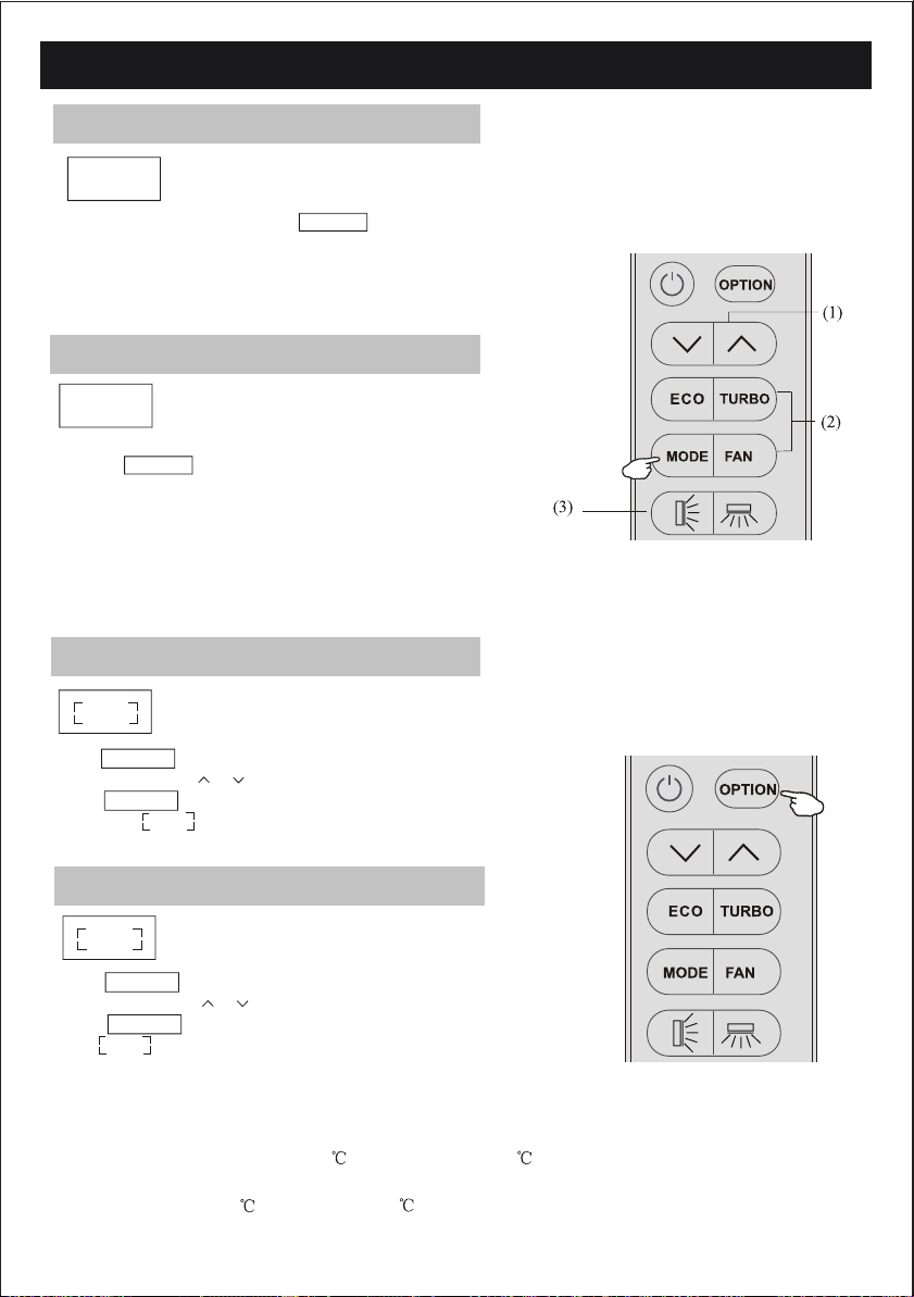
COOLING MODE
The cooling function allows the air condit-
COOL
To activate the cooling function ( COOL ) , press the
MODE button until the symbol COOL
appears on the display.
The cooling function is activated by setting the button
or at a temperature lower than that of the room.
To optimize the function of the air conditioner, adjust
the temperature (1) , the speed (2) and the direction
of the air flow (3) by pressing the button indicated.
ioner to cool the room and at the same time
reduces air humidity.
HEATING MODE
HEAT
To activate the heating function ( HEAT ) , press the
MODE button until the symbol HEAT
appears on the display.
With the button or set a temperature higher than
that of the room..
To optimize the function of the Air conditioner adjust
the temperature ( 1 ), the speed ( 2 ) and the direction
of the air flow ( 3 ) by pressing the button indicated.
In HEATING operation, the appliance can automatically
activate a defrost cycle, which is essential to clean the
frost on the outdoor heat exchanger so as to recover its
heat exchange function.This procedure usually lasts for 2-10
minutes during defrosting,indoor unit fan stop operation.
After defrosting ,it resumes to HEATING mode
automatically.
The heating function allows the air conditioner to heat the room.
DRY MODE
This function reduces the humidity of the
DRY
To set the DRY mode , Press MODE until
DRY appears on the display . An automatic
function of alternating cooling cycles and air
fan is activated.
air to make the room more comfortable.
13
Page 16
OPERATING INSTRUCTIONS
FAN MODE(Not FAN button)
FAN
To set the FAN mode , Press MODE until
FAN appears on the display.
To optimize the function of the air conditioner, adjust
the temperature(1), the speed (2) and the direction of the
air flow (3) by pressing the buttons indicated.
The air conditioner works in only
circulation.
AUTO MODE
AUTO
To activate the AUTO mode of operation,
press the MODE button on the remote controller until
the symbol AUTO appears on the display.
In AUTO mode the run mode will be set automatically
according to the room temperature.
To optimize the function of the air conditioner, adjust
the temperature(1), the speed (2) and the direction of the
air flow (3) by pressing the buttons indicated.
DISPLAY function (Indoor display)
DISPLAY
Press OPTION at the fist time , select the DISPLAY by
pressing the button or until symbol DISPLAY is flashing;
Press OPTION again to switch off the LED display on the
panel, and appears on the remote controller display.
Do it again to switch on the LED display.
Automatic mode.
Switch on/off the LED display on panel.
DISPLAY
SLEEP function
SLEEP
Press OPTION at the first time , select the SLEEP by
pressing the button or until symbol SLEEP is flashing;
Press OPTION again to activate the SLEEP function,
and appears on the display.
SLEEP
Do it again to deactivate this function.
When the SLEEP button is pressed, the air conditioner oper ates a s f ollowing :
1. The sleep lamp is on, the display of temperature will become dark.
2. When selecting CO OL IN G/DRY operation with SLEEP mode, the set
temperature will be raised by 1 1 hour later and by 2 2 hour later.
3. When selecting HEATING op er ation wi th SLEEP mod e, the set temperature
will be dropped by1 1 hour la te r and 2 2 hours lat er.
4. After the System operates in SLEEP mode for 10 hours, it will be c ancelled automatically.
14
Page 17

OPERATING INSTRUCTIONS
ECO function
ECO
In this mode the appliance automatically sets the operation to
achieve energy savings.
1. Press the "ON / OFF" button to turn on appliance and select
a COOLING / HEATING mode.
2. Press the "ECO" button, the appliance will run in ECO mode.
3. Press the "ECO" button again will cancel the mode, "ECO"
will no longer be shown on the display.
NOTE:
The ECO function is available in COOLING and HEATING modes.
Turbo function
To activate turbo function,press the button TURBO
or press the button FAN until symbol appears
on the display.
To cancel this function, press the FAN to switch
other fan speed or press the TURBO button again.
In AUTO/HEAT/COOL/FAN mode,
when you select TURBO feature, it will use the highest
fan setting to blow strong airflow.
the highest fan setting to blow strong airflow.
I FEEL FUNCTION
I FEEL function,
15
Page 18

OPERATING INSTRUCTIONS
TIMER function
TIMER
To set the automatic switch-on /off
of the air conditioner.
Timer setting/change/cancel:
1. Press OPTION at the first time , select the Timer by
pressing the button or until symbol TIMER
is flashing;
2. Press OPTION again, the data symbol like
and TIMER will be flashing;
3. To set the timer or change the timer:
(1)Press the button or to set the expected timer
(Increase or decrease at half-hour intervals)
the symbols h and TIMER both are flashing.
(2) Press OPTION or wait for 5 seconds without any
operation to confirm the timer , the pre-setting
timer like and symbol will be on the display.
TIMER
4. To cancel the timer(if TIMER is on)
Repeat step 1, step 2, then press OPTION or wait for 5
seconds without any operation to cancel the timer .
A sample for the Timer-on as Figure1, Timer-off as Figure2
Note:
All process should be operated in 5 seconds, otherwise
the process will be cancelled.
HEAT
TIMER
TIMER
DISPLAY
DISPLAY
CLEAN
CLEAN
Figure1,Timer-on
when switch off
HEAT
SLEEP
SLEEP
TIMER
TIMER
DISPLAY
DISPLAY
I FEEL
I FEEL
Figure2,Timer-off
when switch on
8 CH
8 CH
16
Page 19

OPERATING INSTRUCTIONS
SELF-CLEAN function
CLEAN
This function helps carry away the accumulated dirt,
bacteria,etc from the indoor hear exchanger.
Press OPTION at the first time while air conditioner is turned off,
select the CLEAN by pressing the button or until symbol
CLEAN
is flashing; Press OPTION again to activate the CLEAN function,
CLEAN
and appears on the display.Do it again to deactivate this
function.
1. This function help carry away the accumulated
dirt, bacteria, etc from the evaporator.
2. This function will run about 30 minutes, and it will return to the
pre-setting mode .You can press to cancel this function during
the process. You will hear 2 beeps when it's finished or cancelled.
3. It's normal if there are some noise during this function process,
as plastic materials expand with heat and contract with cold.
4. We suggest operating this function in the following ambient
condition to avoid certain safety protection features.
Room temp
Outdoor temp
Temp<30
5 <Temp<30
5. We suggest operating this function per 3 months.
8 heating function
8 H
1.Press OPTION at the first time , select the 8 H by
pressing the button or until symbol 8 H
is flashing; Press OPTION again to choose the
8 heating function, and appears on the display.
Do it again or change the mode to deactivate this function.
2.If the air conditioner is standby, this function enable the
air conditioner automatically start heating when the
indoor temperature is equal or lower than 8 , it will return
standby if the temperature is equal or higher than 18 .
It can be set in Cool/Heat/Dry/Fan/Auto mode,
but you need to turn off the unit to activate it.
8 H
17
Page 20

The air conditioner is programmed for comfortable and suitable living conditions as below
if used outside the conditions, certain safety protection features might come into effect.
18
Page 21

19
Page 22

20
Page 23

21
Page 24

22
Page 25

23
Page 26

Refrigerant piping connection
The piping can be run in the 3 directions indicated by
numbers in the picture . When the piping is run in
direction 1or3, cut a notch along the groove on the side
of the indoor unit with a cutter.
Run the piping in the direction of the wall hole and bind
the copper pipes , the drain pipe and the power cables
together with the tape with the drain pipe at the bottom,
so that water can flow freely.
Do not remove the cap from the pipe until connecting
it, to avoid dampness or dirt from entering.
If the pipe is bent or pulled too often , it will become
stiff . Do not bend the pipe more than three times at
one point.
When extending the rolled pipe, straighten the pipe by
unwinding it gently as shown in the picture.
Connections to the indoor unit
1. Remove the indoor unit pipe cap (check that there is
no debris inside).
2. Insert the fare nut and create a flange at the extreme
end of the connection pipe.
3. Tighten the connections by using two wrenches
working in opposite directions.
1
2
Shape the connection pipe
YES
Extending the rolled pipe
3
NO
torque wrench
Indoor unit condensed water drainage
The indoor unit condensed water drainage is fundamental for the success of the installation.
1. Place the drain hose below the piping, taking care not
to create siphons.
2. The drain hose must slant downwards to aid drainage.
3. Do not bend the drain hose or leave it protruding or
twisted and do not put the end of it in water . If an
extension is connected to the drain hose , ensure that
it is lagged when it passes into the indoor unit.
4. If the piping is installed to the right, the pipes, power
cable and drain hose must be lagged and secured onto
the rear of the unit with a pipe connection.
1) Insert the pipe connection into the relative slot.
2) Press to join the pipe connection to the base.
24
YES
NO NO
Page 27

25
Page 28

INSTALLATION MANUAL---Installation of the outdoor unit
ELECTRICAL CONNECTIONS
1. Remove the handle on the right side plate of outdoor unit.
2. Connect the power connection cord to the terminal board.
Wiring should fit that of indoor unit.
3. Fix the power connection cord with wire clamp.
4. Confirm if the wire has been fixed properly.
5. An efficient earth connection must be ensured.
6. Recover the handle.
CONNECTING THE PIPES
Screw the flare nuts to the outdoor unit coupling with
the same tightening procedures described for the indoor
unit.
To avoid leakage, pay attention to the following points:
1. Tighten the flare nuts using two wrenches. Pay atten tion not to damage the pipes.
2. If the tightening torque is not sufficient , there will
probably be some leakage. With excessive tightening
torque there will also be some leakage, as the flange
could be damaged.
3. The surest system consists in tightening the connecti on by using a fix wrench and a torque wrench:in this
case use the table on page 28.
outdoor unit
connection pipes
flare nuts
liquid tap
gas tap
indoor unit
gas valve
wiring diagram on the
back of the cover
screw
remove
the right
side plate
liquid valve
tap
BLEEDING
Air and humidity left inside the refrigerant circuit can
cause compressor malfunction. After having connected
the indoor and outdoor units, bleed the air and humidity
from the refrigerant circuit by using a vacuum pump.
26
service port nut
service port
protection caps
vacuum pump
Page 29

27
Page 30

INVERTER TYPE
MODEL capacity (Btu/h)
Liquid pipe diameter
Gas pipe diameter
Length of pipe with standard charge
Maximum distance between indoor and outdoor unit
Additional refrigerant charge
Max. diff. in level between indoor and outdoor unit
Type of refrigerant(1)
9k
1/4
(6)
3/8
( 9.52)
3m
15m 15m 15m
20g/m 30g/m 30g/m
5m 5m 5m
R32 R32 R32R32
12k
1/4
(6)
1/2
( 12)
4m
15m
20g/m
5m
18k
1/4
(6)
1/2
( 12)
(1) Refer to the data rating label sticked on the outdoor unit.
TIGHTENING TORQUE FOR PROTECTION CAPS AND FLANGE CONNECTION
PIPE
1/4
(6)
3/8
( 9.52)
1/2
( 12)
5/8
( 15.88)
TIGHTENING TORQUE
[N x m]
15 - 20
31 - 35
35 - 45
75 - 80
CORRESPONDING STRESS
(using a 20 cm wrench)
wrist strength
arm strength
arm strength
arm strength
Service port nut
Protection caps
TIGHTENING TORQUE
5m
24k
1/4
(6)
5/8
( 15.88)
[N x m]
7 - 9
25 - 30
5m
28
Page 31

Outdoor handle cover
Front panel
Wiring diagram
Wiring diagram
29
Page 32

30
Page 33

antidust filter
31
Page 34

32
Page 35

Page 36

 Loading...