

Page 1

64LHP4000
SERVICE MANUAL
S59H264LHP400
REAR PROJECTION HDTV
MODEL
In the interests of user-safety (Required by safety regulations in some countries) the set should be restored
to its original condition and only parts identical to those specified should be used.
OUTLINE
This model is based on Model 64LHP5000, but not equipped with the DTV unit. For servicing, refer to the
Service Manual (S29C764LHP5-P, S29C864LHP5-P) for the 64LHP5000 Projector Unit.
CONTENTS
» CHANGING PARTS LIST.............................................................................................................................2
» SPECIFICATIONS........................................................................................................................................3
» OPERATION MANUAL ................................................................................................................................4
» ADJUSTMENT...........................................................................................................................................10
» PARTS LIST ...............................................................................................................................................11
» PACKING OF THE SET .............................................................................................................................16
64LHP4000
Page
SHARP CORPORATION
This document has been published to be used for
after sales service only.
The contents are subject to change without notice.
1
Page 2

64LHP4000
CHANGING PARTS LIST
Ref. No. Description P art No. (64LHP5000) Part No. (64LHP4000) Note
ËË
Ë
ËË
PRINTED WIRING BOARD ASSEMBLIES
Tuner µ-COM Ass’y 9GJAWV1723 9GJAWV1755 Changed
Sub Video Ass’y 9GJAWV1726 9GJA WV1745 Changed
ËË
Ë
ËË
ELECTRICAL PARTS
» TUNER µ-COM ASS’Y
IC2201 TV System Control 9GJPD5462E9 9GJPD5537B9 Changed
IC2202 TV Control 9GJPD5463E9 9GJPD5463B9 Changed
» SUB VIDEO ASS’Y
R6187 9GJRS1/16S0R0J — Abolished
ËË
Ë
ËË
CABINET AND MECHANICAL PARTS
» FRONT VIEW (1/2) PARTS LIST
10 Door Ass’y 9GJAAN1446 9GJAAN1448 Changed
13 Front Panel Ass’y 9GJAMB2630 9GJAMB2639 Changed
26 LED Lens 9GJAAM2730
31 DTV Logo Label 9GJAAX2677 — Abolished
» REAR VIEW (1/2) PARTS LIST
11 Rear Cover (DTV) Ass’y 9GJANE1577 — Abolished
13 Screw 9GJPMB40P160FZ — Abolished
15 Screw 9GJABZ30P060FZ — Abolished
16 DTV Holder 9GJANG2318 — Abolished
» REAR VIEW (2/2) PARTS LIST
13 Special Screw 9GJABA1240 Abolished (1pc.)
24 Cabinet Wire Holder 9GJAEC1263 Abolished (2pcs.)
32 Binde Holder 9GJAEC1785 Abolished (1pc.)
33 Ferrite Core 9GJATX1033 — Abolished
35 AC Cord Holder B 9GJANG2311 — Abolished
36 Wire Harness C (J14) SGJADX2491 — Abolished
37 AC Power Cord B 9GJADG1181 — Abolished
39 Special Screw 9GJABA1271 Abolished (3pcs.)
40 Ferrite Core 9GJATX1031 — Abolished
41 Nylon Clamper 18N 9GJAEC1789 — Abolished
42 Nylon Binder 9GJAEC-093 — Abolished
44 Screw 9GJPMB40P250FZ — Abolished
45 Cabinet (64S) 9GJAMM2941 9GJAMM2980 Changed
» VIDEO BLOCK PARTS LIST
15 Lead Clamper M 9GJAEC1611 — Abolished
21 Model Plate
» PACKING PARTS LIST
1 Upper Carton (64WS) 9GJAHD2996 9GJAHD3020 Changed
11 Remote Control Unit RRMCG1486CESA RRMCG1509CESA Changed
16 Conv. Attention Card 9GJARM1153 9GJARM1161 Changed
17 Operation Manual (EN) 9GJARB1518 9GJARB1525 Changed
38 Barcode Label DLAB-1904EWV0 DLAB-2006WEV0 Changed
……
9GJAAL2296 Added
Quantity changed from
4 to 2.
2
Page 3

Specifications
64LHP4000
Display and amplifier section
Screen size .....................................................................64"
CRT.................................................. 7" High focus CRT x 3
Brightness (White peak) ......................... 400 Foot-Lambert
[White window signal input contrast Max.]
without protective screen
Horizontal resolution.......................... More than 1400 lines
[Input digital test pattern (1400 lines resolution)]
Input terminals ...............................................4 video inputs
4 S-VIDEO input jacks (Y/C separate INPUT)
2 COMPONENT VIDEO INPUT jacks (Y, C
CENTER INPUT jack
Output terminals ..................................... MONITOR/AUDIO
Input terminal signal ratings
Input signal
Video signal:
Composite and S-VIDEO(Y): 1.0 Vp-p (75 ohms
load)
COMPONENT (Y):1.0 Vp-p (75 ohms load)
(C
B/PB, CR/PR): 0.7 Vp-p (75 ohms load)
Audio signal (including CENTER): 500mV rms
Input impedance............................. Video input: 75 ohms
Audio input (including CENTER): 22 k-ohms
Input signal polarity (Video) ........ Synchronized negative
Output terminal signal ratings
Output signal .......... Video signal: 1 Vp-p (75 ohms load)
Audio signal: 500 mV rms (100 % modulation)
Output impedance ........................ Video output: 75 ohms
Audio output: Less than 1 k-ohms
Effective output
Front both channels driven............................. 15 W + 15 W
(THD. 1 % 1 kHz, 8 ohms)
Built-in speaker system ...... 16 cm (6-5/16 in) full range x 2
..............................................6.6 cm (2-9/16 in) tweeter x 2
IR-MOUSE G-LINK Terminal x 1
B/PB, CR/PR)
4 audio inputs
or more
Tuner section
Circuit type...................................... Video signal detection:
PLL full synchronous detection
PLL digital synthesizer system
NTSC Reception channel
VHF; CH2–CH13, UHF; CH14–CH69
CATV (STANDARD, IRC or HRC)
CATV 1-125 CH
Antenna terminal
................................... Antenna terminal, 75 ohms UNBAL,
F-type connector (VHF, UHF MIXED)
Electrical section, miscellaneous
Power requirements...................................120 V AC, 60 Hz
Power consumption ................................................... 343 W
External dimensions .... 1510 (W) x 698 (D) x 1425 (H) mm
59-7/16 (W) x 27-31/64 (D) x 56-1/8 (H) inch
Weight of main unit................................... 152 kg (334.8 lb)
NOTE:
Specifications and design are subject to possible modifications
without notice due to improvements.
3
Page 4

64LHP4000
POWER
STANDBY/ON
INPUT CH RETURN
POWER/
DOWN LOAD
TIMER OPC
Front Panel Functions
A flip-down door conceals the control panel. Push gently and
release, to open the door. To close the door, lift it back up into
place.
NOTE:
If you accidentally pull the door, it may not shut properly. Push the door
back in to shut it.
1 POWER/DOWNLOAD indicator
Lights when power is on. Flashes when downloading the
GUIDE Plus+ program information.
2 Timer indicator
Lights GUIDE Plus+ timer is set.
3 OPC sensor
Sensor to detect the room brightness.
4 POWER b utton (STANDBY/ON)
Press once to turn on the Rear Projection TV. Press again
to turn off the Rear Projection TV.
5 INPUT button
Press to select your program source. Each press of the
INPUT changes the selection to the next source.
TV INPUT 1
INPUT 4 INPUT 3 INPUT 2
6 CHANNEL buttons
Press plus ' or minus " to tune to a higher or lower
channel. Only the preset channels can be tuned in using
these buttons.
7 RETURN button
Press to set the Rear Projection TV to its initial mode.
In some cases, the door may only open slightly when
pushed.
In such cases, open the door with your finger as shown in
the figure at left.
41 2 3 5 6 7
4
Page 5
64LHP4000
VOL
S-VIDEO
INPUT 4
VIDEO L-AUDIO-R
(MONO)
Initial mode
Input selector: Set to TV.
TV channel: Remains at the last channel set.
VOLUME: Remains at the last setting.
MUTING: OFF
VIDEO
MODE: STD
Parameters: Set to 0.
3D Y/C LEVEL: 3
3D NR LEVEL: 3
CNR: OFF
FAV. COLOR: STD.
FLESH TONE: ON
AUDIO
MTS: MAIN
Parameters: Set to 0.
SURROUND: OFF
VIEW
AUTO VIEW: OFF
MODE: SMART STRETCH
V. POSITION: Set to 0.
CC: OFF
OPC: OFF
SYSTEM IN/OUT
SPEAKER: NORMAL
AUDIO OUT: FIXED
• When this button is pressed while adjusting the
outer point convergence, the outer point
convergence returns to the initial mode.
CA UTION:
Do not press any operation button on the Rear Projection
TV or the remote control unit while recording. Signals from
the MONITOR OUTPUT jacks may be temporarily
interrupted when a button is pressed.
ATTENTION
The Rear Projection TV Receiver will not function properly
in the following cases.
• An electrical discharge in the CRT.
• Lightning storms.
• High static electricity environment.
• Poor voltage regulation in the power source.
If the Rear Projection TV does not operate properly, reset it
as follows:
1. Unplug the AC cord.
2. After approximately 1 minute, turn on the power with
switch and 4 POWER button.
If the normal operation cannot be restored after the above
treatment, immediately unplug the power cord and call your
nearest SHARP-authorized service center.
NOTE:
On rare occasions, an electrical discharge may occur inside the
CRT. It makes a short, sharp pop and either no sound is produced
or the volume level changes by itself. The TWIN PICTURE and
SEARCH SCREEN function will be cancelled automatically if an
electrical discharge occurs when this function is engaged.
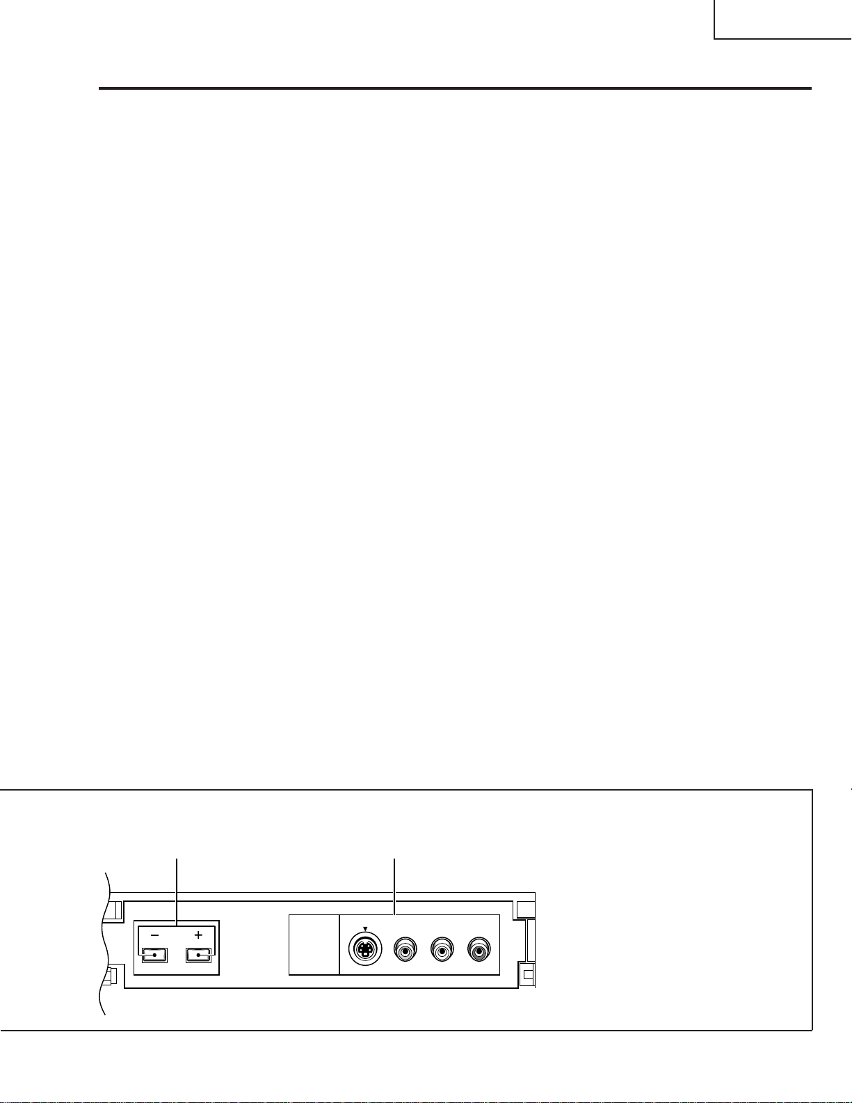
8 V OLUME b uttons
Press plus (+) button to increase the volume, press minus
(–) button to decrease it.
9 INPUT 4 jacks
These inputs are for Video Movie and VCR. Use RCA-type
pin plug cords (the same as those used in Hi-Fi systems)
and S-VIDEO cords for connections. When the audio
source to be connected is monaural, connect the source to
the L-(MONO) jack.
8 9
5
Page 6

64LHP4000
Remote Control Unit Functions
REMOTE CONTR OL UNIT SETTING BUTTONS
2
1
1
9
8
1 Remote control mode select buttons
Use to switch the remote control unit modes.
• This remote control can be used to operate the Rear Projection
TV, a DTV Decoder, and a cable TV box.
• By selecting one of the three mode select buttons, this remote
control can be used to adjust common functions, such as channel
selection, for that device.
2 Light button
When this button is pressed, some buttons on the remote control
unit will light. The lighting will turn off if no operations are performed
within about six seconds.
This button is used for performing operations in dark places.
REAR PROJECTION TV (MONITOR TV)
CONTROL BUTT ONS
1 POWER button
Turns the power of the Rear Projection TV on and off.
2 Input button (TV, INPUT 1 to INPUT 4)
Press the button to select the source you wish to watch. The screen
will display your selection.
5
2
4
7
6
3
3 VIEW MODE button
Press to select the VIEW MODE.
4 ANT-A/B button
Press to switch between ANTENNA-A and ANTENNA-B when you
wish to watch TV.
5 Direct channel selection buttons
Press the button (or buttons) that corresponds to the channel that
you wish to watch.
6 CH (channel)
Press plus or minus to tune in a higher or lower channel.
Only the preset channels can be tuned in using these buttons.
7 MUTE button
Press to temporarily turn off the sound. Press again to return to the
previous volume level.
8 Cursor/ENTER buttons (
, , , : Press to select or adjust items on the menu
ENTER: Press to activate the selected function.
9 FAVORITES buttons
These buttons call up the channels that have been assigned to
them.
, button
, , , , )
screen.
6
Page 7

o
i
64LHP4000
0 TWIN PICTURE/SEARCH screen buttons
TWIN PICTURE: Press to turn the TWIN PICTURE screen function
on and off.
STROBE: Press to turn the STROBE screen on and off.
SEARCH: Press to select the SEARCH screen mode.
SELECT: Selects the screen for switching the channel or
input source.*
FREEZE: When this button is pressed with the regular
screen, the screen will change to the TWIN
PICTURE screen and the picture at the time the
button was pressed will become the sub-picture,
displayed as a frozen image.
"-TWIN CH-': Used to switch the channel for the sub-picture of
the TWIN PICTURE screen.
1
p
e
0
y
u
t
r
q
w
q DISPLAY button
Turns the screen indicators for the input source, channel, setting,
and they will appear for a few seconds.
w FLASHBACK button
Press to switch between the current channel and the channel you
were watching immediately before.
e VOL (volume) +, – buttons
Press plus (+) button to increase the volume, press minus (–) button
to decrease it.
Volume level will appear on the screen as numbers and a bar graph.
The maximum volume level is “63”.
The display will disappear from the screen after 2 seconds.
r MENU button
Press to turn on the menu screen for use in function selection.
Press again to return to normal TV screen.
t GUIDE/TV button
y INFO button
u VCR Plus+ button
i ENTER button
o ACTION button
p
The buttons of t-p listed above are GUIDE Plus+ buttons.
*1 With the 9-SEARCH screen, the search picture’s input source
and channel cannot be switched.
button
7
Page 8

64LHP4000
SHARP DTV DECODER CONTROL BUTT ONS
1
3
2
1 POWER button
Turns the power of a connected Sharp DTV Decoder (such as the
DTV-TU1000) on and off.
2 CH (channel)
Press plus or minus to tune in a higher or lower channel.
3 Direct channel selection button
Press the button (or buttons) that corresponds to the channel that
you wish to watch.
, button
1
2
3
4
CABLE CONTROL BUTT ONS
Cable converters which are made by other makers and are not
preset can also be operated using the remote control unit if buttons
1 to 2 have learned the functions.
1 POWER buttxon
Turns the power of a connected cable converter on and off.
2 Direct channel selection buttons
Press the button (or buttons) that corresponds to the channel that
you wish to watch.
3 CH (channel)
Press plus
4 ENTER button *
Fix the selected channel with the direct channel selection buttons.
* Some manufacturers do not preset ENTER.
, buttons
or minus to tune in a higher or lower channel.
8
Page 9

64LHP4000
VCR CONTROL BUTT ONS
If the VCR is preset by OPERATION OF REMOTE CONTROL
(page 53), the remote control unit button will function as follows
when the mode switch of the remote control unit is set to VCR.
When the input button having the same number as the input
terminal connecting the VCR is pressed, the VCR can be operated
using buttons 1 to 9.
VCR which are made by other makers and are not preset can also
be operated using the remote control unit if buttons 1 to 9 have
learned the functions.
1 Numeric buttons
Use to enter two-digit code numbers when identifying your VCR.
2\\ REW
Press to rewind a tape. For some VCRs you may need to press
STOP first, then REWIND.
In Playback mode, hold button down to view picture moving
rapidly in reverse.
1
2
4
6
3
5
7
8
9
3| PLAY
Press to play back a tape.
4â PAUSE
Press to temporarily stop the tape during playback or recording.
Press again to release Pause.
5 ■ STOP
Press to stop the tape.
6Æ REC
Press to begin recording.
7 FF ||
Press to rapidly advance the tape. For some VCRs, you may
need to press STOP first, then FF.
In Playback mode, hold button down to view the picture moving
rapidly in forward direction.
8 VCR CHANNEL UP (')/ DOWN (")
Press to scan up or down through the channels on the VCR.
9 VCR POWER
Press to turn the VCR on and off.
9
Page 10

64LHP4000
ADJUSTMENT
Ë
Factory ADJ Mode
8
Others OFFSET Mode
Start
1st FAC
Picture quality mode
MOVIE OFFSET
–24
COLOR
Data value
Start
1st FAC
.................. Start adjusting
............ Select 1st factory adjustment mode, then adjust.
<Picture quality>
: COLOR (–64 to 63)
: TINT (–64 to 63)
: CONTRAST (–64 to 63)
: BRIGHT (–128 to 127)
: SHARPNESS (–128 to 127)
: DETAIL (–128 to 127)
: VM (–128 to 127)
: DRV-R (–64 to 63)
OFFSET MODE
Direct Key Screen Display Picture quality mode
(Blue) MOVIE MOVIE OFFSET MODE
(Green) GAME GAME OFFSET MODE
(Red) TV TV OFFSET MODE
COLOR TEMP (STD) COLOR TEMP LOW for STD &
COLOR TEMP (MOVIE)
Note: The 64LHP4000 remote controller does not have the DTV MENU key.
For adjusting the color temperature (movie), use the 64LHP5000
remote controller (RRMCG1486CESA).
(GAME) OFFSET MODE
COLOR TEMP LOW for MOVIE
OFFSET MODE
: DRV-B (–64 to 63)
: CUT-R (–128 to 127)
: CUT-G (–128 to 127)
: CUT-B (–128 to 127)
<Data value section>
or
10
Page 11

64LHP4000
Mark Ref. No. Part No. ★ Description Code Mark Ref. No. Part No. ★ Description Code
PARTS LIST
PARTS REPLACEMENT
Parts marked with "å" are important for maintaining the safety of the
set. Be sure to replace these parts with specified ones for maintaining the safety and performance of the set.
"HOW TO ORDER REPLACEMENT PARTS"
To have your order filled promptly and correctly, please furnish the
following informations.
1. MODEL NUMBER 2. MARK
3. REF. NO. 4. PART NO.
5. DESCRIPTION 6. CODE
7. QUANTITY
in USA: PWB and part assemblies are supplied through the
board exchange program, please contact your local
Regional Service Office for additional details.
MARK ★: SPARE PARTS-DELIVERY SECTION
Parts marked by "NSP" are generally unavailable because they are
•
not in our Master Spare Parts List.
The å mark found on some component parts indicates the
•
importance of the safety factor of the part.
Therefore, when replacing, be sure to use parts of identical
designation.
When ordering resistors, first convert resistance values into code
•
form as shown in the following examples.
Ex.1 When there are 2 effective digits (any digit apart from 0), such
as 560 ohm and 47k ohm (tolerance is shown by J=5%, and
K=10%).
560 Ω→56 × 101→ 561 .......... RD1/4PU 5 6 1 J
47k Ω→47 × 103→ 473 .......... RD1/4PU 4 7 3 J
0.5 Ω→R50 ................................. RN2H R 5 0 K
1 Ω→1R0 ................................. RS1P 1 R 0 K
Ex.2 When there are 3 effective digits (such as in high precision
metal film resistors).
5.62k Ω→ 562 × 101→ 5621........ RN1/4PC 5 6 2 1 F
Parts marked by ✩ are important parts which relate in X-rays
•
radiation.
If any of these parts need to be replaced, always replace with
specified parts.
Parts marked by × are important parts which relate in X-rays
•
radiation. If a failure occurs in any of these parts, replace the printed
circuit board assembly where the relevant part has already been
adjusted as a working component. Do not replace the actual part
itself. If any part marked by × is replaced, there is danger of being
exposed to X-rays.
NOTES
Mark Ref. No. Part No. ★ Description Code Mark Ref. No. Part No. ★ Description Code
PRINTED WIRING BOARD ASSEMBLIES
(NOT REPLACEMENT ITEM)
9GJAWV1710 – Power Supply Ass'y —
✩ 9GJAWV1731 –
9GJAWV1712 – Amp Ass'y —
NSP 9GJAWV1721 – CONV.DAC Ass'y —
9GJAWZ6333 – Conver. DAC Ass'y —
9GJAWZ6335 – Connector Ass'y —
9GJAWZ6337 – Front Control Ass'y —
9GJAWZ6339 – Front Input Ass'y —
9GJAWZ6348 – LED DPO Ass'y —
9GJAWZ6350 – SR Ass'y —
9GJAWZ6351 – SR BNC Ass'y —
9GJAWV1722 – AV I/O Ass'y —
9GJAWV1755 – Tuner µ-COM Ass'y —
9GJAWV1724 – Video Ass'y —
9GJAWV1725 – Signal Ass'y —
NSP 9GJAWV1733 –
9GJAWZ6344 – R CRT Drive Ass'y —
9GJAWZ6345 – G CRT Drive Ass'y —
9GJAWZ6346 – B CRT Drive Ass'y —
9GJAWZ6354 – AC IN Ass'y —
Deflection Service Ass'y
AC IN, CRT Service Ass'y
—
IC2201 9GJPD5537B9 M TV System Control BN
IC2202 9GJPD5463B9 M TV Control BU
FRONT VIEW (1/2) PARTS LIST
10 9GJAAN1448 M Door Ass’y BC
13 9GJAMB2639 M Front Panel Ass’y BF
—
9GJAWV1755
TUNER µ-COM ASS'Y
INTEGRATED CIRCUITS
9GJAWV1745 – Sub Video Ass'y —
9GJAXF1084 –
9GJAXF1098 – RF SW —
TV Front End System Unit
(No Servise Parts.)
(No Servise Parts.)
—
11
Page 12

64LHP4000
Mark Ref. No. Part No. ★ Description Code Mark Ref. No. Part No. ★ Description Code
13 9GJAXF1098 – RF Switch —
VIDEO BLOCK PARTS LIST
NSP 1 9GJANA1584 – Video Chassis —
2 9GJAWV1724 – Video Ass'y —
3 9GJAWV1722 – A V I/O Ass'y —
4 9GJANC2322 M Rear Panel (S) BB
7 9GJABN-087 M Hexagonal Duct Nut AB
8 9GJBBZ30P080FZ M Screw AB
9 9GJBBZ30P080FC M Screw AA
10 9GJAWV1723 – Tuner µ-Com Ass'y —
11 9GJAWV1725 – Signal Ass'y —
12 9GJAWV1726 – Sub Video Ass'y —
NSP 16 9GJAEP-214 – Purse Lock L —
NSP 17 9GJANG2305 – PWB Side Holder —
14 9GJWAX0F160N10 M Washer AA
18 9GJAWZ6351 – SR BNC Ass'y —
20 9GJADX2490 M
21 9GJAAL2296 M Model Plate AG
4P Housing Wire (J13)
AH
VIDEO BLOCK
Refer to Signal Ass'y block
12
Page 13

64LHP4000
Mark Ref. No. Part No. ★ Description Code Mark Ref. No. Part No. ★ Description Code
REAR VIEW (1/2) PARTS LIST
1 9GJAME2296 M Mirror Case(51) BF
2 9GJABA1240 M Special Screw AA
3 9GJPYC40T140FZ M Screw AB
4 9GJAMM2929 M Rear Cover BG
5 9GJAEC1622 M Blind Sheet (PVC) AD
6 9GJAEC1627 M Mirror Case Cushion AD
7 9GJABZ30P100FZ M Screw AB
NSP 9 9GJAEC1263 – Cabinet Wire Holder —
REAR VIEW (1/2)
8 9GJABA1269 M Screw AC
10 9GJAEC1778 M Screen Cushion 64 AL
13
Page 14

64LHP4000
Mark Ref. No. Part No. ★ Description Code Mark Ref. No. Part No. ★ Description Code
REAR VIEW (2/2)
14
Page 15

64LHP4000
Mark Ref. No. Part No. ★ Description Code Mark Ref. No. Part No. ★ Description Code
REAR VIEW (2/2) PARTS LIST PACKING PARTS LIST
✩ 1 9GJAWY1415 M
✩ 2 9GJAWY1413 M CRT Service Ass'y G CQ
✩ 3 9GJAWY1414 M
✩ 4 9GJAMR3121 M Lens Ass'y CA
5 9GJFBT40P120FZ M Screw AC
6 9GJABA1168 M Screw (Steel) AB
7 9GJAMZ40P080FZ M Screw AB
NSP 8 9GJANA1541 – CRT Front Frame (62) —
NSP 9 9GJANA1542 – CRT Rear Frame (62) —
10 9GJACZ40P080FM M Screw AK
NSP 11 9GJANG2118 – CRT Front Holder —
NSP 12 9GJANG2119 – CRT Rear Holder —
13 9GJABA1240 M Special Screw AA
14 9GJAEC1257 M Cord Holder AD
NSP 15 9GJAAX2497 – Tube Label —
16 9GJAEC-441 M Rivet AC
NSP 17 9GJANA1497 – CRT Stand Holder (R) —
NSP 18 9GJANA1496 – CRT Stand Holder (L) —
19 9GJPMB50P250FZ M Screw AC
20 9GJABA1121 M Special Screw AE
NSP 21 9GJAMM2939 – Back Cover Panel —
22 9GJAEC1779 M Back Cover Cushion AL
23 9GJABA1241 M Special Screw AD
NSP 24 9GJAEC1263 – Cabinet Wire Holder —
25 9GJABA1210 M Screw (Steel) AC
NSP 26 9GJANG1958 –
27 9GJAWZ6350 – R/C Receiver Ass'y —
NSP 28 9GJAMR2563 – Tray (PLS) —
NSP 29 9GJAAX2672 – Solder Warning Label —
NSP 31 9GJANG2307 – AC Cord Holder A —
NSP 32 9GJAEC1785 – Binde Holder —
å 34 9GJADG1180 M AC Power Cord AU
38 9GJBBZ30P080FZ M Screw AB
39 9GJABA1271 M Special Screw AA
43 9GJADX2505 M 1P Lead Wire AE
45 9GJAMM2980 M Cabinet (64S) DB
CRT Service Ass'y 64B
CRT Service Ass'y 64R
Remote Sensor Holder
CR
CR
—
1 9GJAHD3020 M Upper Carton (64WS) BU
2 9GJAHD2995 M Under Carton (64W) BD
3 9GJAHA2222 M Upper Pad L AS
4 9GJAHA2223 M Upper Pad R AS
5 9GJAHA2224 M Under Pad L AV
NSP 7 9GJAHG1288 –
NSP 8 9GJAHG1230 – Packing Sheet (60) —
NSP 9 9GJAHG1290 –
NSP 11 RRMCG1509CESA – Remote Control Unit —
NSP 13 – –
NSP 18 9GJARM1057 – Caution Card —
NSP 23 9GJAHG1076 – Wrapper Bag —
NSP 24 9GJAHG1222 – Literature Bag —
NSP 26 9GJAHG1286 – Packing Sheet (64W) —
NSP 30 9GJAAP1600 –
NSP 33 9GJAHA2228 – Under Cusion A —
NSP 34 9GJAHA2229 – Under Cusion B —
NSP 35 TGAN-1029MEZZ – Registration Card —
NSP 36 RRMCK0023CEZZ – IR Mouse —
6 9GJAHA2225 M Under Pad R AV
10 9GJAHG1289 M
14 9GJAHC1032 M CU Packing Case AN
15 9GJABA1239 M Special Screw AB
16 9GJARM1161 M Conv. Attention Card AH
17 9GJARB1525 M
22 9GJABA1226 M Screw AC
25 9GJAHB1202 M Panel Case (64W) BF
27 9GJAAK2729 M Contrast Screen 64W CL
28 9GJARH1161 M
29 9GJAAP1599 M
31 9GJAND1163 M Panel Frame H (64W) BE
32 9GJAND1164 M Panel Frame V (64W) BD
37 9GJAHC1024 M Packing Case A AM
38 DLAB-2006WEV0 M Barcode Label
Vinyl Sheet 64W Upper
Packing Sheet 64W Under
Vinyl Sheet 64W Under
Alkaline Dry Battery (LR6,AA)
Operation Manual (EN)
(Panel Frame Attaching Screw)
(for Panel)
Acrylic Caution Card (S)
Frame Cover H (64WS)
Frame Cover V (64WS)
—
—
AS
—
BH
AD
AS
—
OTHERS
9GJADX2231 M 1P Lead Wire (J3) BD
9GJADX2232 M 1P Lead Wire (J4) AT
9GJADX2233 M 1P Lead Wire (J5) AW
9GJADX2289 M 1P Lead Wire (J6) AF
9GJADX2290 M 1P Lead Wire (J7) AF
9GJADX2291 M 1P Lead Wire (J8) AF
9GJADX2484 M 4P Housing Wire (J2) AH
9GJADX2485 M Wire Harness A (J10) BU
9GJADX2487 M Wire Harness B (J11) BE
15
Page 16

64LHP4000
Mark Ref. No. Part No. ★ Description Code Mark Ref. No. Part No. ★ Description Code
PACKING OF THE SET
17,18,24,35
22x12
23
29-31
3
4
25-28,32
38
15
37
36
10
1
16
8
7
11
13
9
5
15
14
TQ0659-S
May. 1999 Printed in Japan
SY. KG
6
2
33
33
34
SHARP CORPORATION
A V Systems Group
Quality & Reliability Control Center
Yaita, Tochigi 329-2193, Japan
16
 Loading...