

SHARP 64LHP400, 64LHP4000 Service Manual

64LHP4000
SERVICE MANUAL
S59H264LHP400
REAR PROJECTION HDTV
MODEL
In the interests of user-safety (Required by safety regulations in some countries) the set should be restored
to its original condition and only parts identical to those specified should be used.
OUTLINE
This model is based on Model 64LHP5000, but not equipped with the DTV unit. For servicing, refer to the
Service Manual (S29C764LHP5-P, S29C864LHP5-P) for the 64LHP5000 Projector Unit.
CONTENTS
» CHANGING PARTS LIST.............................................................................................................................2
» SPECIFICATIONS........................................................................................................................................3
» OPERATION MANUAL ................................................................................................................................4
» ADJUSTMENT...........................................................................................................................................10
» PARTS LIST ...............................................................................................................................................11
» PACKING OF THE SET .............................................................................................................................16
64LHP4000
Page
SHARP CORPORATION
This document has been published to be used for
after sales service only.
The contents are subject to change without notice.
1

64LHP4000
CHANGING PARTS LIST
Ref. No. Description P art No. (64LHP5000) Part No. (64LHP4000) Note
ËË
Ë
ËË
PRINTED WIRING BOARD ASSEMBLIES
Tuner µ-COM Ass’y 9GJAWV1723 9GJAWV1755 Changed
Sub Video Ass’y 9GJAWV1726 9GJA WV1745 Changed
ËË
Ë
ËË
ELECTRICAL PARTS
» TUNER µ-COM ASS’Y
IC2201 TV System Control 9GJPD5462E9 9GJPD5537B9 Changed
IC2202 TV Control 9GJPD5463E9 9GJPD5463B9 Changed
» SUB VIDEO ASS’Y
R6187 9GJRS1/16S0R0J — Abolished
ËË
Ë
ËË
CABINET AND MECHANICAL PARTS
» FRONT VIEW (1/2) PARTS LIST
10 Door Ass’y 9GJAAN1446 9GJAAN1448 Changed
13 Front Panel Ass’y 9GJAMB2630 9GJAMB2639 Changed
26 LED Lens 9GJAAM2730
31 DTV Logo Label 9GJAAX2677 — Abolished
» REAR VIEW (1/2) PARTS LIST
11 Rear Cover (DTV) Ass’y 9GJANE1577 — Abolished
13 Screw 9GJPMB40P160FZ — Abolished
15 Screw 9GJABZ30P060FZ — Abolished
16 DTV Holder 9GJANG2318 — Abolished
» REAR VIEW (2/2) PARTS LIST
13 Special Screw 9GJABA1240 Abolished (1pc.)
24 Cabinet Wire Holder 9GJAEC1263 Abolished (2pcs.)
32 Binde Holder 9GJAEC1785 Abolished (1pc.)
33 Ferrite Core 9GJATX1033 — Abolished
35 AC Cord Holder B 9GJANG2311 — Abolished
36 Wire Harness C (J14) SGJADX2491 — Abolished
37 AC Power Cord B 9GJADG1181 — Abolished
39 Special Screw 9GJABA1271 Abolished (3pcs.)
40 Ferrite Core 9GJATX1031 — Abolished
41 Nylon Clamper 18N 9GJAEC1789 — Abolished
42 Nylon Binder 9GJAEC-093 — Abolished
44 Screw 9GJPMB40P250FZ — Abolished
45 Cabinet (64S) 9GJAMM2941 9GJAMM2980 Changed
» VIDEO BLOCK PARTS LIST
15 Lead Clamper M 9GJAEC1611 — Abolished
21 Model Plate
» PACKING PARTS LIST
1 Upper Carton (64WS) 9GJAHD2996 9GJAHD3020 Changed
11 Remote Control Unit RRMCG1486CESA RRMCG1509CESA Changed
16 Conv. Attention Card 9GJARM1153 9GJARM1161 Changed
17 Operation Manual (EN) 9GJARB1518 9GJARB1525 Changed
38 Barcode Label DLAB-1904EWV0 DLAB-2006WEV0 Changed
……
9GJAAL2296 Added
Quantity changed from
4 to 2.
2

Specifications
64LHP4000
Display and amplifier section
Screen size .....................................................................64"
CRT.................................................. 7" High focus CRT x 3
Brightness (White peak) ......................... 400 Foot-Lambert
[White window signal input contrast Max.]
without protective screen
Horizontal resolution.......................... More than 1400 lines
[Input digital test pattern (1400 lines resolution)]
Input terminals ...............................................4 video inputs
4 S-VIDEO input jacks (Y/C separate INPUT)
2 COMPONENT VIDEO INPUT jacks (Y, C
CENTER INPUT jack
Output terminals ..................................... MONITOR/AUDIO
Input terminal signal ratings
Input signal
Video signal:
Composite and S-VIDEO(Y): 1.0 Vp-p (75 ohms
load)
COMPONENT (Y):1.0 Vp-p (75 ohms load)
(C
B/PB, CR/PR): 0.7 Vp-p (75 ohms load)
Audio signal (including CENTER): 500mV rms
Input impedance............................. Video input: 75 ohms
Audio input (including CENTER): 22 k-ohms
Input signal polarity (Video) ........ Synchronized negative
Output terminal signal ratings
Output signal .......... Video signal: 1 Vp-p (75 ohms load)
Audio signal: 500 mV rms (100 % modulation)
Output impedance ........................ Video output: 75 ohms
Audio output: Less than 1 k-ohms
Effective output
Front both channels driven............................. 15 W + 15 W
(THD. 1 % 1 kHz, 8 ohms)
Built-in speaker system ...... 16 cm (6-5/16 in) full range x 2
..............................................6.6 cm (2-9/16 in) tweeter x 2
IR-MOUSE G-LINK Terminal x 1
B/PB, CR/PR)
4 audio inputs
or more
Tuner section
Circuit type...................................... Video signal detection:
PLL full synchronous detection
PLL digital synthesizer system
NTSC Reception channel
VHF; CH2–CH13, UHF; CH14–CH69
CATV (STANDARD, IRC or HRC)
CATV 1-125 CH
Antenna terminal
................................... Antenna terminal, 75 ohms UNBAL,
F-type connector (VHF, UHF MIXED)
Electrical section, miscellaneous
Power requirements...................................120 V AC, 60 Hz
Power consumption ................................................... 343 W
External dimensions .... 1510 (W) x 698 (D) x 1425 (H) mm
59-7/16 (W) x 27-31/64 (D) x 56-1/8 (H) inch
Weight of main unit................................... 152 kg (334.8 lb)
NOTE:
Specifications and design are subject to possible modifications
without notice due to improvements.
3

64LHP4000
POWER
STANDBY/ON
INPUT CH RETURN
POWER/
DOWN LOAD
TIMER OPC
Front Panel Functions
A flip-down door conceals the control panel. Push gently and
release, to open the door. To close the door, lift it back up into
place.
NOTE:
If you accidentally pull the door, it may not shut properly. Push the door
back in to shut it.
1 POWER/DOWNLOAD indicator
Lights when power is on. Flashes when downloading the
GUIDE Plus+ program information.
2 Timer indicator
Lights GUIDE Plus+ timer is set.
3 OPC sensor
Sensor to detect the room brightness.
4 POWER b utton (STANDBY/ON)
Press once to turn on the Rear Projection TV. Press again
to turn off the Rear Projection TV.
5 INPUT button
Press to select your program source. Each press of the
INPUT changes the selection to the next source.
TV INPUT 1
INPUT 4 INPUT 3 INPUT 2
6 CHANNEL buttons
Press plus ' or minus " to tune to a higher or lower
channel. Only the preset channels can be tuned in using
these buttons.
7 RETURN button
Press to set the Rear Projection TV to its initial mode.
In some cases, the door may only open slightly when
pushed.
In such cases, open the door with your finger as shown in
the figure at left.
41 2 3 5 6 7
4
64LHP4000
VOL
S-VIDEO
INPUT 4
VIDEO L-AUDIO-R
(MONO)
Initial mode
Input selector: Set to TV.
TV channel: Remains at the last channel set.
VOLUME: Remains at the last setting.
MUTING: OFF
VIDEO
MODE: STD
Parameters: Set to 0.
3D Y/C LEVEL: 3
3D NR LEVEL: 3
CNR: OFF
FAV. COLOR: STD.
FLESH TONE: ON
AUDIO
MTS: MAIN
Parameters: Set to 0.
SURROUND: OFF
VIEW
AUTO VIEW: OFF
MODE: SMART STRETCH
V. POSITION: Set to 0.
CC: OFF
OPC: OFF
SYSTEM IN/OUT
SPEAKER: NORMAL
AUDIO OUT: FIXED
• When this button is pressed while adjusting the
outer point convergence, the outer point
convergence returns to the initial mode.
CA UTION:
Do not press any operation button on the Rear Projection
TV or the remote control unit while recording. Signals from
the MONITOR OUTPUT jacks may be temporarily
interrupted when a button is pressed.
ATTENTION
The Rear Projection TV Receiver will not function properly
in the following cases.
• An electrical discharge in the CRT.
• Lightning storms.
• High static electricity environment.
• Poor voltage regulation in the power source.
If the Rear Projection TV does not operate properly, reset it
as follows:
1. Unplug the AC cord.
2. After approximately 1 minute, turn on the power with
switch and 4 POWER button.
If the normal operation cannot be restored after the above
treatment, immediately unplug the power cord and call your
nearest SHARP-authorized service center.
NOTE:
On rare occasions, an electrical discharge may occur inside the
CRT. It makes a short, sharp pop and either no sound is produced
or the volume level changes by itself. The TWIN PICTURE and
SEARCH SCREEN function will be cancelled automatically if an
electrical discharge occurs when this function is engaged.
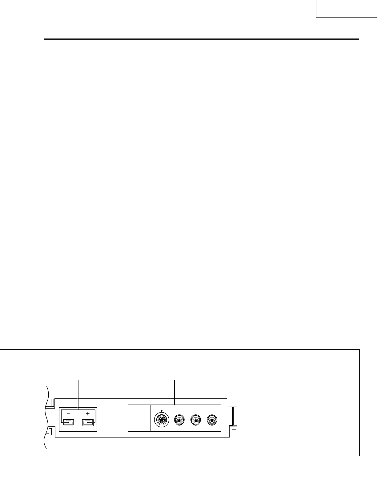
8 V OLUME b uttons
Press plus (+) button to increase the volume, press minus
(–) button to decrease it.
9 INPUT 4 jacks
These inputs are for Video Movie and VCR. Use RCA-type
pin plug cords (the same as those used in Hi-Fi systems)
and S-VIDEO cords for connections. When the audio
source to be connected is monaural, connect the source to
the L-(MONO) jack.
8 9
5
 Loading...