

Page 1
SHARP
SERVICE MANUAL
S81G314VT10X1
m
VIDEO TV
MODEL ‘I
In the interests of user-safety (Required by safety regulations
in some countries) the set should be restored to its original con-
dition and only parts identical to those specified should be used.
CONTENTS
.
SPECIFICATIONS
.
IMPORTANT SERVICE NOTES
i
.
DISASSEMBLY AND REASSEMBLY
.
FUNCTION OF MAJOR MECHANICAL PARTS
.
ADJUSTMENT, REPLACEMENTANDASSEMBLY OF MECHANICAL UNITS
.
ADJUSTMENT OF THE ELECTRICAL CIRCUITRY
l
TROUBLESHOOTINGGUIDE
. BLOCKDIAGRAM ..........................................................
l
SIGNAL FLOW SYMBOLS AT A GLANCE
. WAVEFORMS .............................................................
l
OVERALLDIAGRAM
.
SCHEMATICDIAGRAMS
. WlRlNGSlDEPWBs .........................................................
l
REPLACEMENT ELECTRICAL PARTS LIST
.
EXPLODEDVIEWS
.
PACKINGOFTHESET
............................................................
................................................
............................................
...................................
................................
.................................................
.......................................
........................................................
.....................................................
.......................................
..........................................................
.......................................................
4v
70x1
\
2
3
4
6
.........
B
34
49
69
go
91
95
97
115
121
137
141
SHARP
1
CORPORATION
Page 2
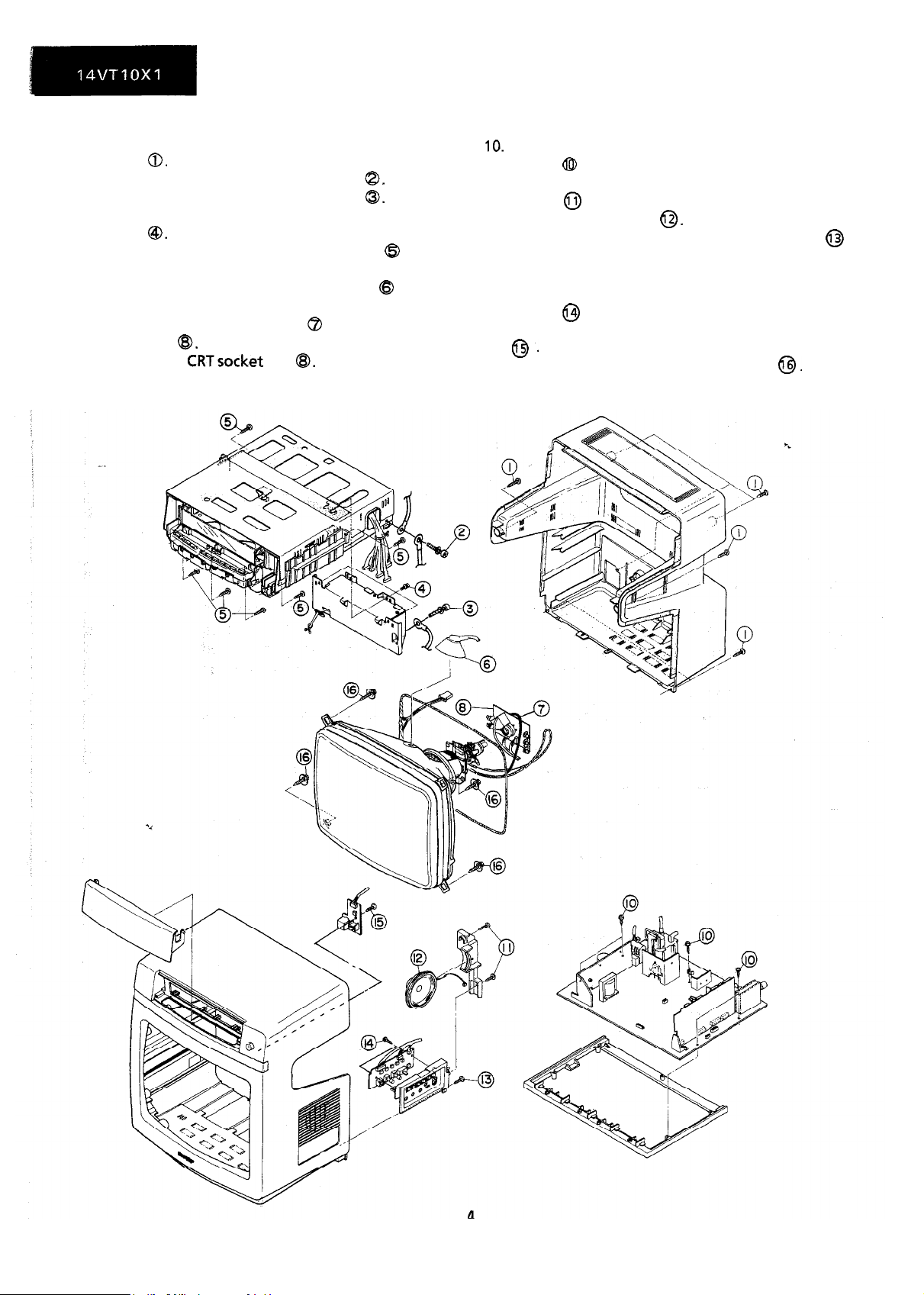
DISASSEMBLY AND REASSEMBLY
Remove the seven back cabinet fastening
1.
screws
Remove the one wire fastening screw
2.
Remove the one wire fastening screw
3.
4.
Remove the three VCR’s power unit fastening
screws @.
Remove the six VCR fastening screws 0 and
5.
remove the VCR with the VCR’s operation.
6.
Remove the CRT’s second anode cap @ from
the CRT.
7.
Remove the “L2” lead wire @ from the CRT
socket unit
8.
Remove the
9.
Remove the TV mother unit with the frame
from the front cabinet.
0.
@I.
CRTsocket
unit
8.
@.
@I.
10.
Remove the five TV mother unit fastening
screws 0 from the frame.
11.
Remove the two speaker holder fastening
screws 0 and remove the holder.
12.
Remove the speaker
13.
Remove the control unit fastening screw
and remove the control unit from the front
cabinet.
14.
Remove the two control unit fastening
screws @ .
15.
Removethe one control unit fastening screw
0.
16.
Remove the four CRT fastening screws
0.
0.
@
Page 3
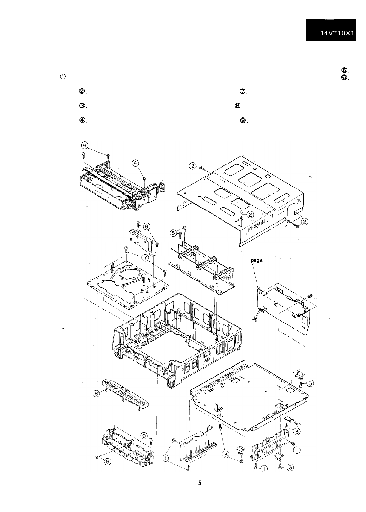
DISASSEMBLY AND REASSEMBLY OF THE VCR SECTION
1. Remove the eight VCR holder fastening screws
a.
2. Remove the four upper cabinet fastening
screws
8.
3. Remove the seven bottom plate fastening
screws
Q.
4. Remove the four cassette housing fastening
screws
@.
5. Remove the five main PWB fastening screws
6. Remove the two head amp fastening screws
@.
@.
7. Remove the four mechanism chassis fastening
screws
@.
8. Release the seven operation panel fastening
clips @ and remove the operation upper panel.
9. Remove the six operation holder fastening
screws
@.
The VCR power unit removal
is described in the
previous
Page 4
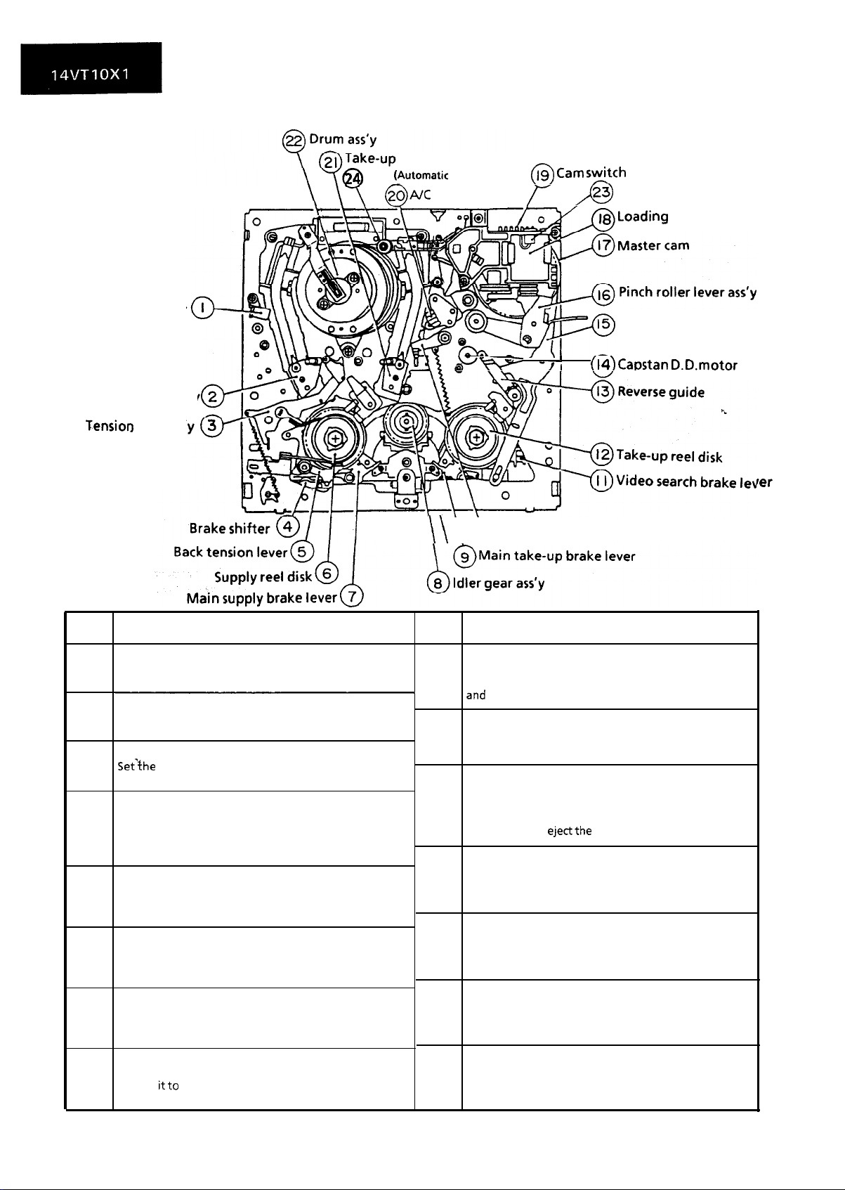
FUNCTION OF MAJOR MECHANICAL PARTS (TOP VIEW)
pole base ass’y
AHC
(fwtomatic
\
@A/C
head cleaner)
head ass’y
($) Cam stitch
23 Dew sensor
x)
Loadi
ng
motor
Full erase head ass’y
Supply pole base
Tension arm ass’
No.
1.
Full erase head ass’y
Erase the whole records on the tape in the recording
mode.
3.
Tension arm ass’y
Detects the tension of tape while running, and brakes
the supply reel disk via the tension band.
4.
Brake shifter
Set-the position of brake or the like in accordance with
the modes such as stop and playback.
5.
Back tension lever
Bakes the supply reel disk to a certain degree to
prevent tape slackening during “half-loading”,
“loading” and “shifting from playback to video search
rewind”.
7.
Main supply brake lever
Brakes the supply reel disk to prevent tape slackening
when the unit is stopped in fast forward or rewind
mode.
9.
Main take-up brake lever
Brakes the take-up reel disk to prevent tape slackening
when the unit is stopped in fast forward or rewind
mode.
10.
Half-loading lever
Bring the tape in contact with the A/C head, putting it
in half-loading state in the fast forward or rewind
mode.
11.
Video search brake lever
It is in contact with the take-up reel disk normally, and
brakes
itto
the videosearch rewind mode.
ass’y
Function
a certain degree. It applies larger brake in
au-
\ \
@Half-loading lever
No.
13.
Reverse guide
Pulls out the tape in the video search rewind mode,
and controls the tape drive train height with the upper
and
lower guides.
15.
Relay shifter lever
Transmits the operation of the master cam to the
brake shifter, and operates the reverse guide.
16.
Pinch roller lever ass’y
Press-fits the tape to the capstan during tape running.
The right protrusion switches the clutch of the cassette
housing control assembly in “tape eject”, and makes
the mechanism
17.
Master cam
Turns clockwise during loading, and counterclockwise
during unloading, and moves the shifter or the like in
accordance with each mode.
Loading motor
18.
A motive power which drives the mechanism. It
transmits the power to the master cam and cassette
housing control assembly via the belt.
19.
Cam switch
Rotates synchronously with the master cam, and
detects the position of each mode by means of the
internal switch
23. Dew sensor
An element which detects condensation inside the
unit. This element is activated, when it senses
condensation, to interrupt the mechanism.
-/I
ejectthe
I
(14) Caostan
Function
tape.
Relay
shifter lever
D.D.motor
rer
6
Page 5
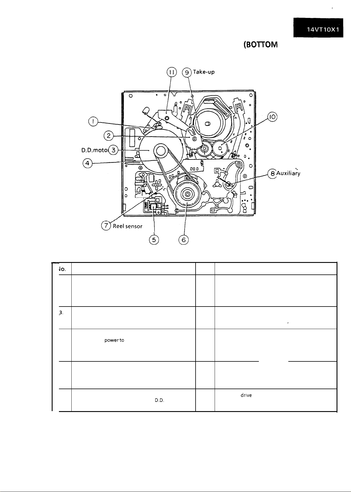
FUNCTION OF MAJOR MECHANICAL PARTS (BOmOM VIEW)
Slow brake lever
Loading relay gear 2
Capstan D.D.motor 3
Reel belt
@-
Relay gear drive lever
o-
0
@
@Take-up
loading gear
IO
Supply loading gear
D
8
-4
AuxiliaFy
brake lever
fast forward
Brake solenoid 5
powerto
Function
run the tape to the reel pulley.
IlO.
1.
Slow brake lever
Gets in contact with the capstan D.D. motor linking to
the master cam in the slow still mode, and brakes it to a
certain
Capstan D.D. motor
3.
A motive power which runs the tape. It transmits the
power via the reel belt.
4.
Reel belt
Transmits the
Brake solenoid
5.
Adsorbs and holds the brake shifter in the fast forward Shifts the supply pole base and guide roller via the
and rewind modes, and releases it in the stop mode.
6.
Reel pulley
Transmits the power of the capstan
reel disk via the reel idler.
degree.
0
D.D.
motor to the Transmits the movement of the master cam to the
6 Reel pulley
d
No.
7.
8.
9.
10.
11.
Function
Reel sensor
An element which sheds the light onto the reflection
plate affixed to the bottom side of the reel disk, and
detects the rotation of the reel disk through receiving
the reflected light.
Auxiliary fast forward brake lever
Brakes the supply reel disk to a certain degree in the
fast forward and rewind modes.
Take-up loading gear
Shifts the take-up pole base and guide roller via the
loading relay gear, and applies the tape around the
drum assembly, as well as transmits the power to the
supply loading gear.
Supply loading gear
take-up loading gear, and applies the tape around the
drum assembly.
Relay gear
take-up loading gear via the loading relay gear.
drove
lever
’
7
Page 6
ADJUSTMENT, REPLACEMENT AND ASSEMBLY
OF MECHANICAL UNITS
Here we will describe a relatively simple service
work in the field, not referring to the more
complicated repairs which would require the use of
special equipment and tools (drum assembly
We are sure that the easy-to-handle tools listed
below would be more than handy for periodical
maintenance to keen the machine in its oriainal
working condition.
replacement, for example).
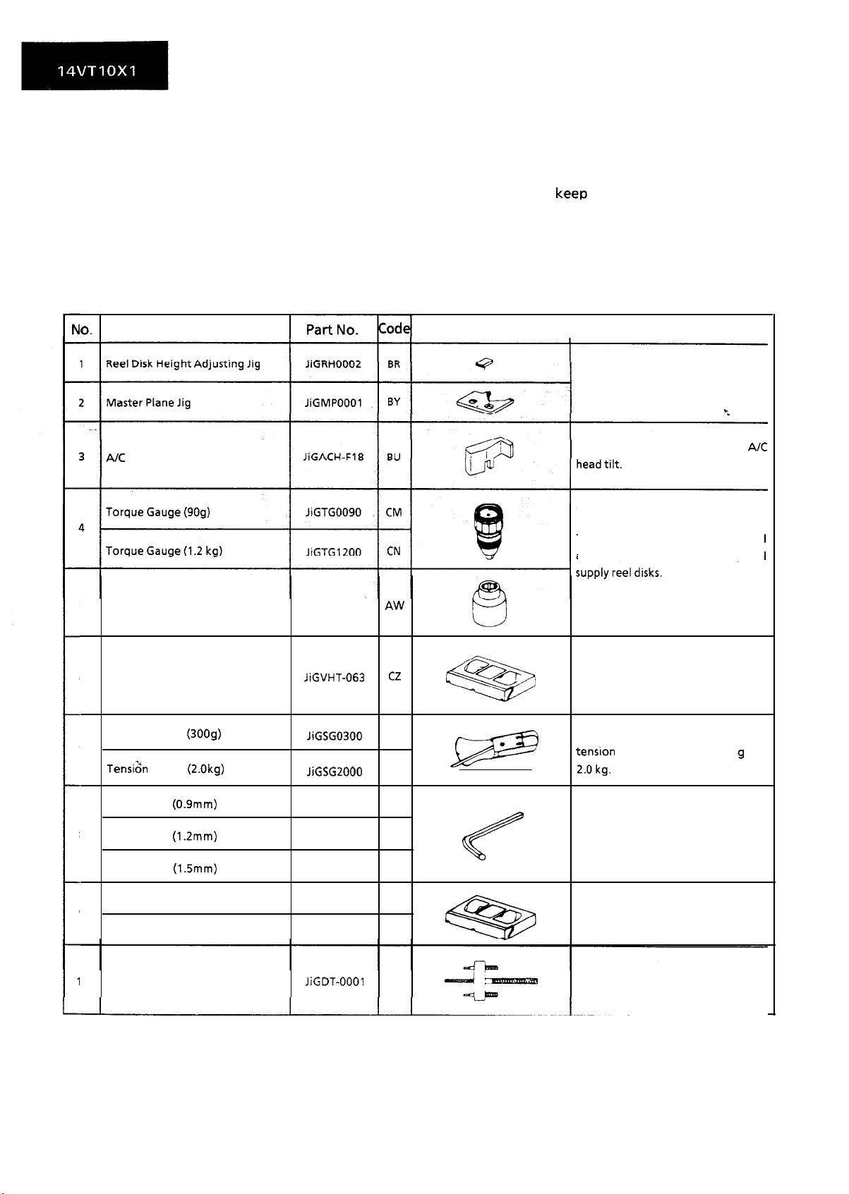
TOOLS NECESSARY FOR ADJUSTING THE MECHANICAL UNITS
The following tools are required for proper service and satisfactory repair.
0.
AK
Head Tilt Adjusting Jig
Jig Item Configuration
I
These Jigs are used for checking and
adjusting the reel disk height
This Jig is used for setting the
These Jigs are used for checking and
adjusting the torque
Remarks
c
of take-up and
A/C
Gauge Head
5
Cassette Torque Meter
6
Tension Gauge (3009)
7
Tens&
Gauge (2.0kg)
Hex Wrench (0.9mm) JiGHW0009 AE
8
Hex Wrench (1.2mm)
Hex Wrench (1.5mm) JiGHWOO15 AE
Alignment Tape (PAL) VROCPSV CD
9
Alignment Tape (NTSC) VROATSV CD
0
Drum Replacing Jig
JiGTH0006
JiGVHT-063 C2
JiGSG0300
JiGSG2000
JiGHWOO12 AE
JiGDT-0001
AW
BF
BS
BG
This cassette torque meter is used
%
Q
6
for checking and adjusting the
torque of take-up for measuring
tape back tension.
There are two Gauges used for the
tensron measurements, 300 g and
*.okg.
These Jigs are used for loosening or
tightening special hexagon type
screws.
These tapes are especially used for
electrical fine adjustment.
This is used for replacement of the
VCR’s upper drum.
8
Page 7
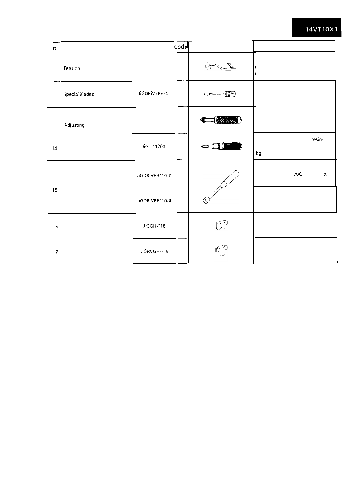
-
0.
1
rension Gauge Adapter
-
jpecial
2
Jig Item
Bladed Screwdriver
Part No.
JiGADP003
JiGDRiVERH-4
C-:odc
-
BK
-
AP
-
Configuration
Remarks
rhis Jig is used with the tension
gauge. Rotary Transformer
Clearance Adjusting Jig.
This Screwdriver is used for
adjusting the guide roller height.
Tension Band and Plate
3
9djusting
Torque Driver
14
Box Driver
15
Retaining Guide Height
16
Adjusting Jig
Reverse Guide Height
17
Adjusting Jig
Jig
JiGDRiVER-
JiGTDl200
JiGDRiVER 10-7
JiGDRiVER 10-4
JiGGH-F18
JiGRVGH-F18
-
-
-
-
BM
-
CB
AS
AV
BU
BU
-
c
;“.:;
This Jig is used for adjusting the
tension band and tension plate.
This is used to screw down resin-
made parts: the specified torque is 5
kg.
This Jig is used for height
adjustment of the
position.
This Jig is used for height
adjustment of the retaining guide.
This jig is used for height
adjustment of the retaining guide.
This Jig is used for height
adjustment of the reverse guide.
PJC
head and X-
9
Page 8
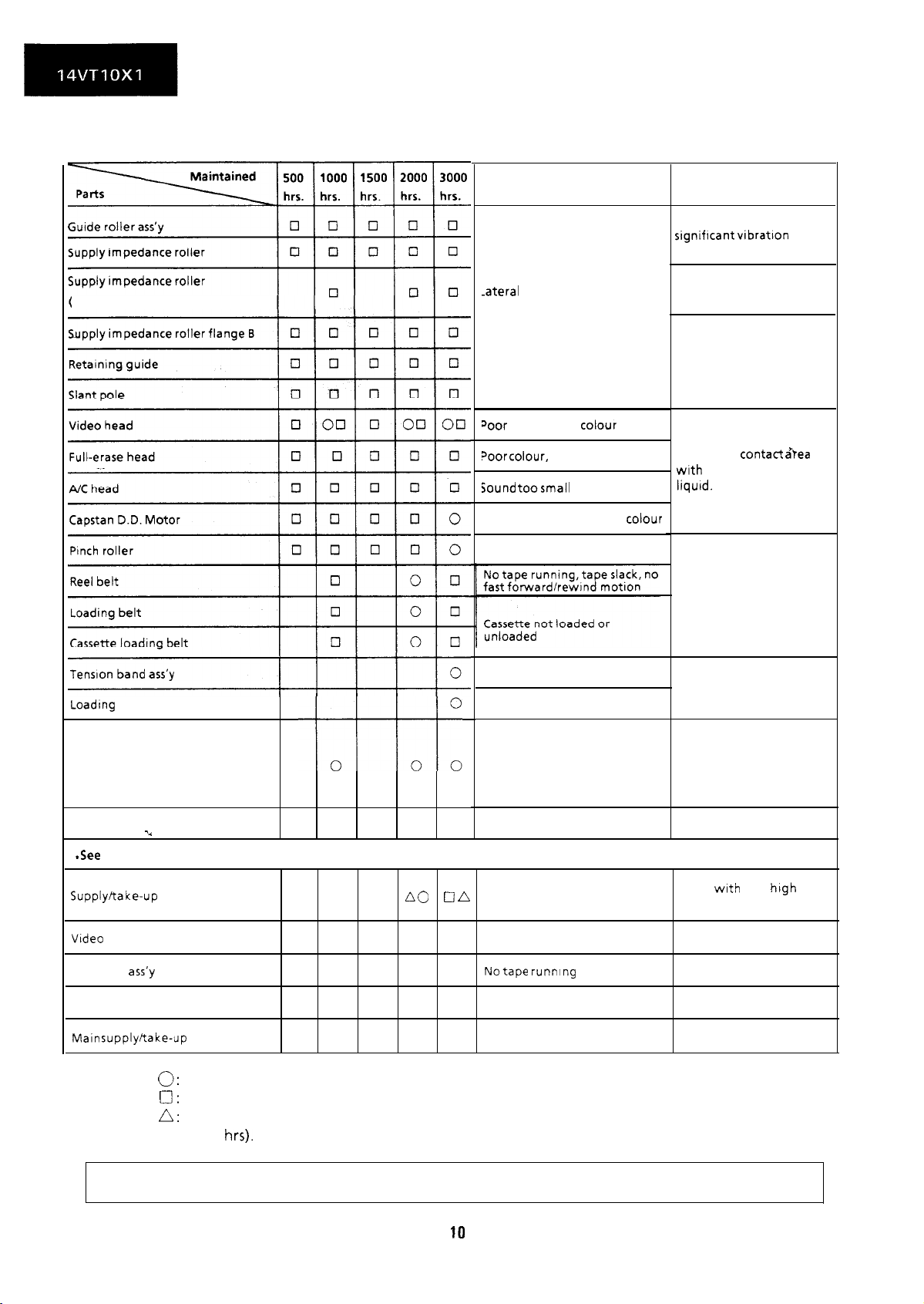
MECHANICAL PARTS REQUIRING PERIODICAL INSPECTION
Use the following table as a guide to maintain the mechanical parts in good operating condition.
inner hole and shaft)
Possible symptom encountered
-atera
noises
-lead occasionally blocked
Door
S/N ratio, no
Door colour,
Sound toosmall
No tape running, uneven
No tape running, tape slack
colour
beating
or distorted
colour
Remarks
Abnormal rotation or
significant vibration
requires replacement
Clean with pure high
quality isopropyl alcohol.
Clean tape contact part
with the specified cleaning
liauid.
Clean tape
with
liquid.
Clean rubber and rubber
contact area with the
specified cleaning liquid.
contact &ea
the specified cleaning
Loadfng Motor
Automatic Head Cleaner
Reel block*
*See
Supply/take-up
Vtdeo search brake lever
Idler gear
Reel Pulley
Maln
NOTE:
-4
the table below for servicing the reel block parts.
reel disks
ass’y
supply/take-up
brake levers
0:
Part replacement.
cl:
Cleaning (For cleaning, use a lint-free cloth dampened with pure isopropyl alcohol).
A:
Oil refilling (The indicated point should be lubricated with high quality spindle oil every
1000
hrs).
no
on
0 n
0
0
on no on
0
Lateral image swing
Cassette not loaded or unloaded
See the chart below
No tape running, tape slack
Notape running
Tape slack
Replace the roller of the
cleaner when it wears
down. Just change the
video head cleaner arm
assembly for new one.
Clean
with
quality Isopropyl alcohol.
pure htgh
If the reading is out of the specified value, clean or replace the part.
10
Page 9

R,EMOVAL AND REASSEMBLY OF
CASSETTE HOUSING CONTROL ASSEMBLY
0
Removal
1.
Set the cassette ejected condition in the cassette
eject mode.
2.
Unplug the recorder from the main source.
Follow the procedures below in the specified
3.
order.
a) Remove the cassette loading belt
b) Disconnect the FFC (full Flat Cable)
c) Remove the cassette housing installation
screws
0.
d) Slide and pull out the cassette housing control
assembly
upward @I.
~-I-
/==h
- _Q3
Cassette housing
setscrew
0.
8.
Place the unit in the eject mode in removal or
5.
reassembly of the cassette housing control
assembly.
6.
Load the cassette once onto the cassette housing
control
assembly
after reassembly. (If the
cassette housing control assembly normally
operates after this, the phases of mechanism and
the
cassette
controller are accurately adjusted
after ejection.)
MECHANICAL OPERATION CHECK
WITHOUT
When power is on, the general operations of the
mechanism can be checked without a cassette.
Note the following points.
1. Check video search rewind and rewind, rotating
the take-up reel disk @ by hand (in either
C1I.c G,\-LC ,,,““d.
2. When the stop button is pressed, the mechanism
does
to the eject mode and stops.
3. When the stop button is pressed in the playback,
video search rewind, and video search forward
modes, the supply reel disk 0 keeps on rotating
for several seconds for elimination of tape slack
in the course of shifting to the eject mode. In
such a case, rotate the take-up reel disk
somewhat by hand, and the supply reel disk
stops, which can reduce the working time.
CASSElTE
!rse
direction). If it is not rotated,
*
works to shift
not
stop at a normal stop position. It shifts
the’Lmechanism
to
@
0
Insert the tab of
the cassette hosing
control assembly to
the mechanism chassis.
-.
0
Reassembly
Figure 1-l.
1. Before installation of the cassette housing
control assembly, place the unit in the stop mode
with the power on, then unplug the power cord.
(The main body is placed in the eject mode.)
2. Follow the procedures for removal in the reverse
order.
Notes:
1. Be sure to unplug the power cord in removal and
reassembly.
2. Keep the cassette loading belt free from grease.
In case of its adhesion, clean the belt.
3. In using a magnet screw driver, be sure to keep it
away from
the
A/C
head, FE (Full Erase) head, or
the drum.
4. In removal and reassembly, take care not to hit
the
cassette
housing control assembly or tools
against the guide pin, drum, or the like
thereabout.
REpLAC~liACil’ fiC \Il,h”l” \“,,,rrl
ASSEMB
Cassette housing
Cassette housing frame
, E
LY
IVI c IY I
(R)
Figure
u r
l-2.
vv u n WI
VvnrcL
11
Page 10
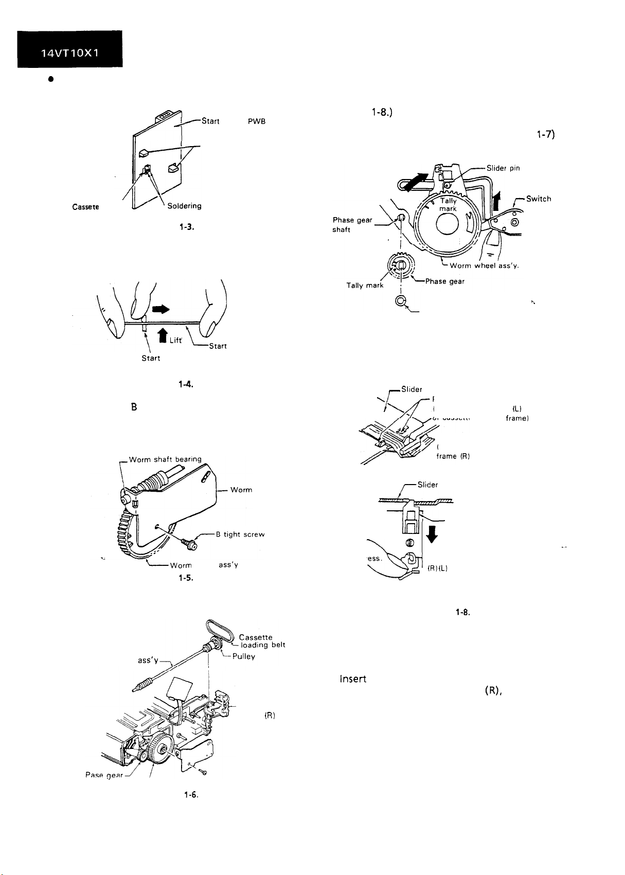
0
Removal
1. Unsolder the cassette switch connectors (No. 16,
17) from the stat-t sensor PWB.
/Start
sensor
PWB
r/7
Start sensor
fixing hook
Cassete
switch
connector
Figurer
l-3.
2. Lift the start sensor PWB pressing the two start
sensor PWB fixing hooks inward.
PWB
5. Place the slider pin just above the worm wheel
(Figure l-7). (The retainer of the slider is locked
at two positions hen. So unlock it as in the
Figure
6. Pull out the worm wheel assembly toward you
pressing the switch lever upward. (Figure
l-8.)
Cut washer
l-7)
-s
witc:h lever
-Qqd
Start
sensor PWB fixing hook
Figure
3. Unscrew one B tight screw to detach the worm
bracket.
Note: The worm shaft bearing can easily come
out of position. So be careful not to lose
it.
-Worm
Figure
4. Remove the worm shaft assembly, pulley, and
cassette loading belt all from the cassette
housing frame (R).
Worm shaft
ass’y
l-4.
wheel
l-5.
Start sensor PWB
bracket
ass’y
-Cassette
frame
hosing
(R)
Figure l-7.
_
Slider
Retainer opening
rSlider
(Also provided on the
of cassette housing frame)
Cassette housing
i,
Retainer
IL)
side
--Id
t
@
Press.
Cassette housing frame
i
(R) (Ll
side
59
Figure
1-8.
l
Reassembly
1. Turn the phase gear clockwise until the slider
comes to a halt in the cassette insertion
direction. (See the Figure l-9.)
2. Insert the set up worm wheel gear assembly into
the cassette housing frame
mark on the phase gear with the mark on the
worm wheel gear. Detach the cut washer on the
phase gear assembly and the phase gear for
easier installation of worm wheel assembly.
Note: Make sure that the slider pin is in the
groove of the drive gear arm.
(R),
matching the
Worm wheel
Figure
l-6.
ass’y
12
Page 11
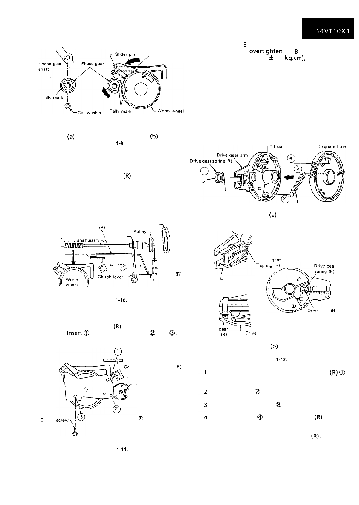
\
Drive gear arm
(4
Figure
l-9.
b)
3. install the pulley and the cassette loading belt on
the worm shaft assembly. Couple the clutch to
the clutch lever. And mount them together in
the cassette housing frame
(R).
Note: Keep in mind that the clutch switching
lever should be in the correct position.
The mechanism might malfunction if the
lever is slightly out of position. (See page
14.)
Cassette housing frame Ft)
.
worm
c
.,
shaft ass.“-. 1
Cassette loading belt
\
Clutch
\
7
Pullev
7
5. Tighten one B tight screw.
Note: Do not over-tighten the
B
tight screw (no
more than 5.0 t 0.5 kg.cm), because the
lower threads of the screw hole at the
resin-made boss can be broken.
6. Place the start sensor PWB on the cassette
housing frame (R).
Note: Check that the switch connectors (No. 16,
17) are in the cassette switch mounting
hole.
7. Finally resolder the cassette switch connector to
the start sensor PWB.
REASSEMBLY OF DRIVE GEAR
Worm wheel
Drive gear spring lR)
Reciprocating spring
(4
Drive gear arm
Cassette
‘housing
frame
(R)
shaft bearing
Figure
l-10.
4. Attach the worm bracket to the worm shaft
assembly. Place them onto the boss on the
cassette housing frame
Note:
B
tight
Inset-t 0
before screwing into 8 and
Worm bracket
Cassette housing frame
Figure
(R).
ssette housing frame
Switch lever
l-11.
(R)
0.
(RI
boss
Drive oear
L
Drive gear arm
Drive
spring
F
w
oea%
(RI
LDrive
#-
(Drive gear bottom view)
gear arm
Drive gear
spring shaft
(RI
b)
Figure
1-12.
Pass the tip of the drive gear spring
through the square hole of the drive gear (R) to
hook the spring in position.
Hook one end 0 of the reciprocating spring to
the catch of the drive gear(R).
Hook the other end Q of the reciprocating
spring to the catch of the worm wheel.
insert the pillar @ of the drive gear
square hole of the worm wheel. Turn the worm
wheel somewhat counterclockwise for insertion
of the worm wheel to the drive gear
(R),
the reciprocating spring is at work.
(R)
into the
because
(R) 0
13
Page 12

REPLACEMENT OF CASSETTE LOADING
BELT
Figure
1-13.
1. Remove the start sensor PWB 0 and worm
’
bracket Q from the cassette housing frame(R).
2. Remove the worm shaft assembly
3. Replace the cassette loading belt @ with a new
one.
Notes:
Do not
the worm bracket in position. The specified
torque is 5.0 + 0.5
Make sure that the cassette loading belt is free
from grease. If stained with grease, clean the
belt with the cleaning liquid.
Perform checking of the clutch switch lever for
proper action.
overtighten
the B tight screw which holds
kg.cm.
-
Worm shaft ass’y
t
sensor PWB
Worm bracket
8.
1. First make sure that the tip of the switch lever is
held at the rib of the drive gear (R).
2. Check that the rib of the cassette housing frame
(R)
and the concavity of the clutch lock lever are
engaged.
3. Finally be sure that the relationship between the
clutch lever and the clutch, as well as between
the clutch and the pulley, are correct as in the
Figure l-l 5.
Pulley
Check that the clutch is engaged
wtth
0
Resetting
the pulley through the
Figure
1-15.
coupling.
Take the following steps to reset the clutch if it is
unlocked or if the switch lever and the clutch lock
lever are unlocked.
lever
CHECKING THE CLUTCH SWITCH LEVER
l
Checking
Place the mechanism in the cassette eject mode
when removing and attaching the cassette housing
from and to the mechanism chassis.
Make
housing such as the clutch switch lever is in
position
Note
Figure
cassette eject mode.
sureenough
that each part in the cassette
If not, it causes malfunction.
:
1-14
shows the position of each part in the
Swtch
level
Rib 2’
Drove
f=Ilb
of cassktre
‘i
gear houslng frame
Figure l-14
‘- Clutch lock lever
(RI
Clutch release
se lever
.~
Figure
Clutch lock lever
l-16.
Rib
of cassette housmg frame
iK1
Shift the slider by turning the coupling in the
arrow direction (clockwise) until the slider pin is
at the bottom of the slider groove as shown in
the Figure
l-16.
(The loading mode)
Note: Note that the slider is equipped with a
lock mechanism. Unlock the locks on
cassette dousing frame
(L)
and
(R)
side
before shifting the slider.
When the position is set as shown in the Figure
l-
16, push the clutch release lever in the direction
of the arrow by hand until the clutch lock lever
becomes tightly locked by the rib of the cassette
housing frame
(R).
Then turn the coupling counterclockwise until
the slider reaches the cassette insertion opening
and the reciprocating spring is activated.
Note: There is no need to unlock the slider when
shifting the slider to the cassette insertion
opening. Just keep shifting the slider.
14
Page 13
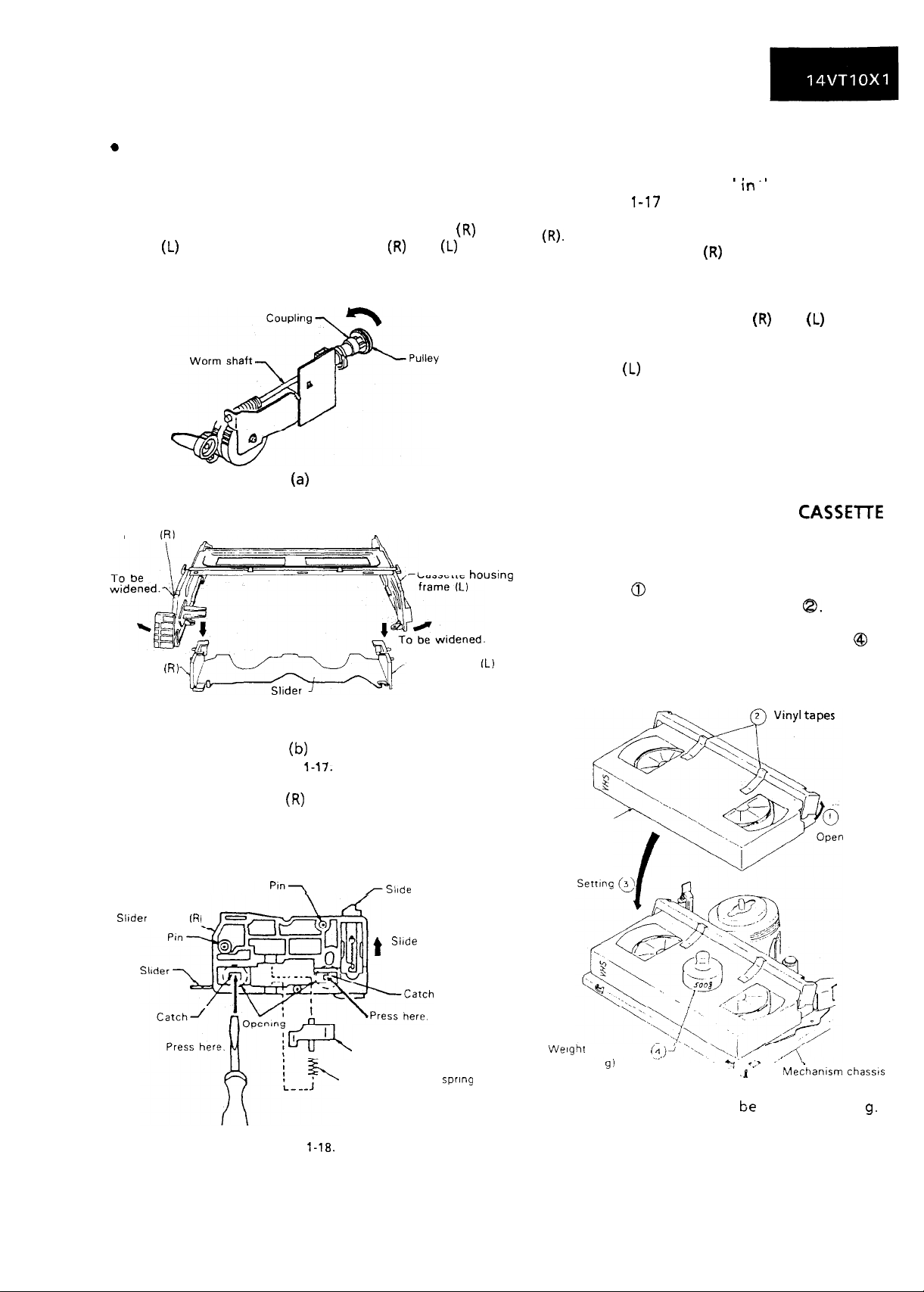
REPLACEMENT OF LOCK RELEASE LEVER
0
Removal
Place the slider in the cassette down position.
1.
(Turn the coupling on the worm shaft clockwise
until the slider is in the cassette down position.)
Note: Before shifting, unlock the slider.
Slightly widen the cassette housing frames
2.
and
(L)
to unhook the slider holders
(R)
and
(L)
(R)
of
the slider assembly off the grooves of the
cassette housing frames.
(4
4.
Remove the lock release lever
from the slider
holder(R)
l
Reassembly
1.
Follow the steps for removal In tne reverse order.
(See Figures
Attach the lock release lever to the slider holder
2.
1-17
and l-18.)
I. _I
(R).
Slide the slider holder
3.
(RI
downward so that the
two catches of the slider holder (R) fit the
opening of the slider.
4.
Slightly widen the cassette housing frames, and
set the pins of slider holders
(R)
and
(L)
into the
grooves of the cassette housing frames.
Note: Check if the pins of the slider holders (R)
and
(L)
fit the grooves of the cassette
housing frames, and if the drive gear arm
is sufficiently engaged with the slider
holders.
5.
Turn the coupling counterclockwise until the
slider is at the cassette insertion opening.
Cassette housing
frame (RI
Slider holder
(RI
(b)
Figure 1-17.
3. Lift the slider holder
the slider by pressing two catches with a thin tip
screw driver. Take care not to damage the
catches.
Slider holder
V?
(R)
upward about 2mm off
/Slide
Cassette houslng
Slider holder (Li
lock catch
Slide it upward
about 2 mm.
TO RUN A TAPE WITHOUT THE
CASSETTE
HOUSING CONTROLASSEMBLY
1. Plug in the power cord.
2. Turn on the power switch.
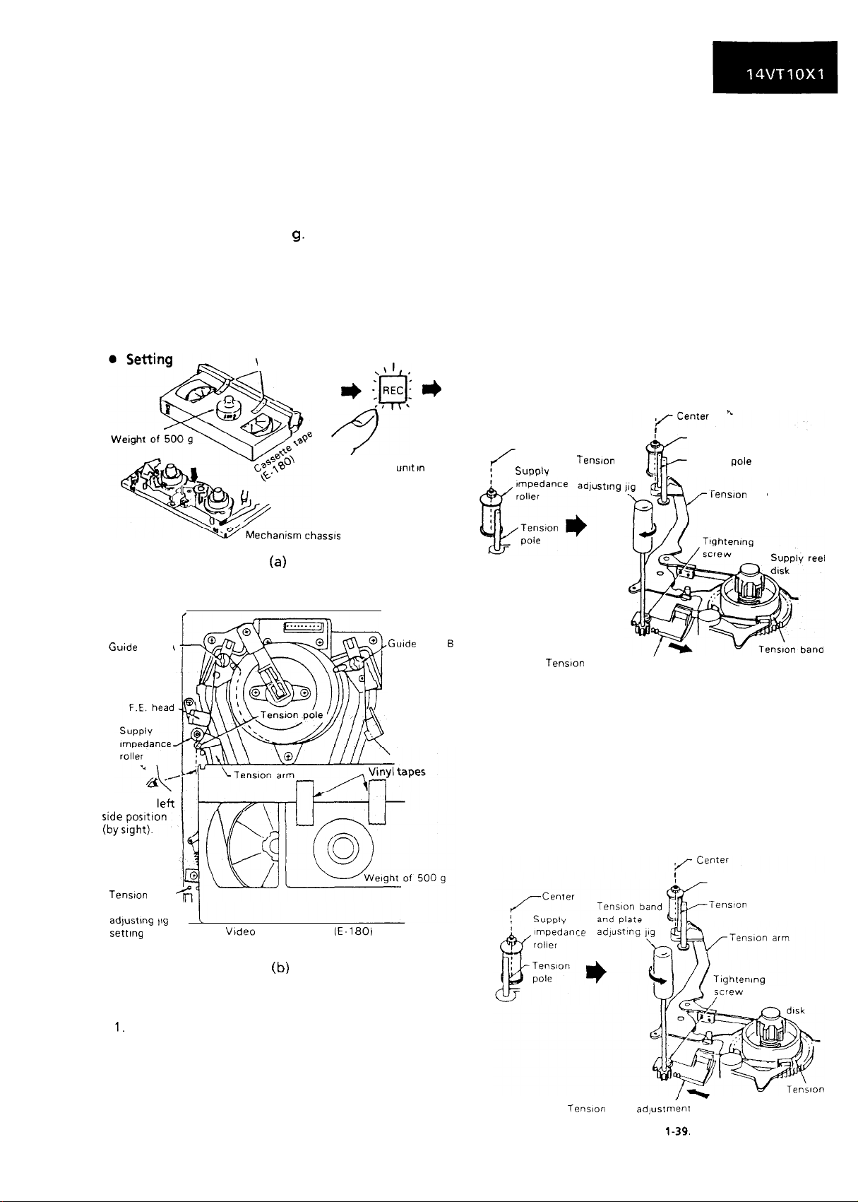
3. Open the lid 0 of a cassette tape by hand.
4. Hold the lid with a pair of vinyl tapes
5. Set the cassette tape in the mechanism chassis.
6. Weight the cassette tape with a weight @ to
prevent float.
7. Perform running test.
Cassette tape
8.
here
Figure
Lock release lever
Lock release lever spring
l-18.
15
Wetght to prevent i,,
1500 gi
float
Note:
The weight should not be more than 500
)J
Figure l-19.
.,T
,
. .
.y
.1
>
Mechanism
chassis
g.
Page 14
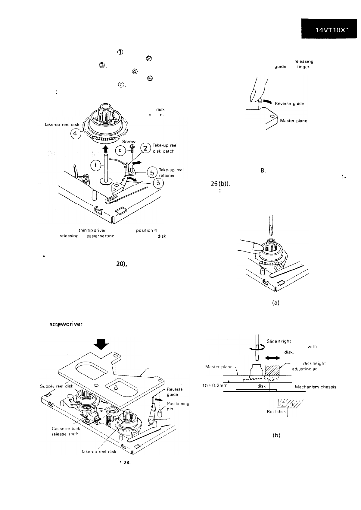
REPLACEMENT AND HEIGHT CHECKING
AND ADJUSTMENT OF REEL DISKS
Remove the cassette housing control assembly.
1.
Set the mechanism in the playback mode with no
2.
cassette tape in place. Unplug the power cord.
Set the idler gear in the center (neutral).
3.
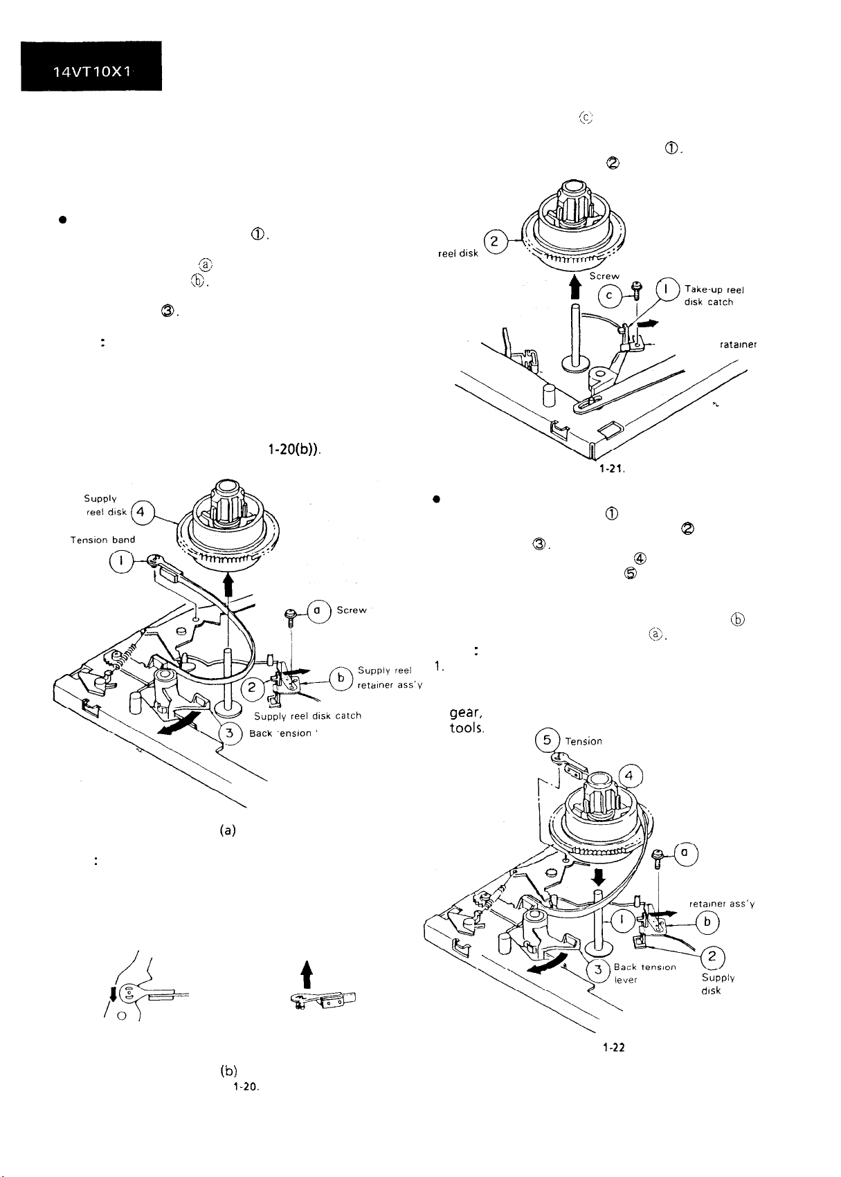
0
Removal (Supply reel disk)
Remove the tension band 0. (Take care not to
1.
deform it.)
Unscrew the screw @ and remove the supply reel
2.
retainer assembly
Release the supply reel disk catch and back
3.
tension lever
4.
Pull the supply reel disk upward.
Notes
:
1. Take care not to deform the tension band.
2. Check and adjust the tension pole position. (See
page 2 1.)
3. Be careful not to damage the gear and the idler
gear on the supply reel disk.
4. Press the tension band in the direction of the
arrow for removal (see Figure
(6>.
0.
1-20(b)).
enston ever
l
Removal (Take-up reel disk)
1. Unscrew the screw
cc/
and remove the take-up
reel retainer.
2. Release the take-up reel disk catch
0.
3. Pull the take-up reel disk Q upward.
-
Take-up
reel
disk
Take-up reel ratamer
Figure
l-21.
0
Reassembly (Supply reel disk)
1.
Clean the reel disk shaft 0 and apply oil to it.
2.
Release the supply reel disk catch 8 and back
tension lever
Install a new supply reel disk @ onto the shaft.
3.
Replace the tension band @ around the supply
4.
0.
reel disk, and insert it to the hole of the tension
arm.
5.
Replace the supply reel retainer assembly @ in
place, and tighten up the screw
Notes
:
1.
Take enough care not to deform the tension
(4.
band during installation of the supply reel disk.
2. Be careful not to damage the supply reel disk
aear,
back tension lever, catch, or the like with
Fool;.
ension band
Note
When the tension band is pressed in the
:
direction of the arrow for removal, the
catch is hard to be deformed.
t
v
b)
Figure
l-20.
16
/ 0
Q
L I-
rzl
&m
.-c
4
Figure
1-22
Supply reel disk
0
Screw
w
Supply reel
T’
retamer
S‘;bply
d!sk catch
ass’y
reel
Page 15
l
Reassembly (Take-up reel disk)
1. Clean the reel disk shaft @ and apply oil to it.
2. Release the take-up reel catch 8 and video
search brake lever
a.
3. Install a new take-up reel disk @I onto the shaft.
4. Replace the take-up reel retainer @ in position
and tighten up the screw
Note
:
0.
Take care not to damage the video search brake
lever.
Clean the reel disk shaft well.
and apply
PJ
011
to
It.
Video search
brake lever
Set the master plane releasmg
the reverse guide by a fmger.
Figure l-25.
2. Check that the reel disk is lower than part A but
higher than part B. If the height is not correct,
adjust the height adjusting screw (see Figure
26
(b)).
Note
:
Whenever replacing the reel disk, perform the
height checking and adjustment.
l-
Apply a thin ttp drwer to the arrow
releasing for easier
setting
of the take-up reel dtsk
Figure l-23.
posItton In
* After reassembly, check the video search rewind
back tension (see page
20),
and check the brake
torque (see page 22).
l
Height checking and adjustment
Note:
Place the master plane onto the mechanism unit,
taking care not to hit the drum (see Figure l-24)
1. For height adjustment, press the reel disk with a
finger, and turn. it right and left with a
screwdriver
(see Figure l-26 (a)).
Setting
Master plane
/-
lO%O.Zmm
(4
Slide It right and left.
and check contact
the reel disk.
r
_
I
&yg_im’+ ‘> .2
Reel disk
I
1
wth
Reel disk
adlustIng 119
height
Mechanism chassis
Figure
(b)
Figure l-26
1-24.
17
Page 16
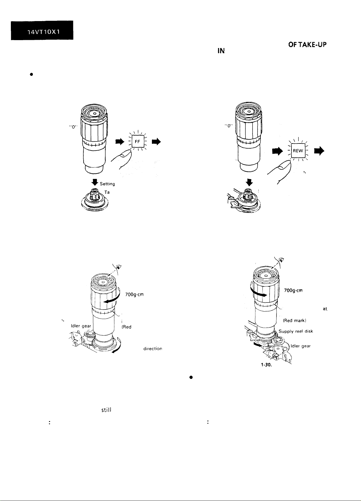
CHECKING AND ADJUSTMENT OF TAKE-UP
TORQUE IN FAST FORWARD MODE
l
Remove the cassette housing control assembly.
0
Setting
CHECKING AND ADJUSTMENT
OFTAKE-UP
TORQUE IN REWIND MODE
Remove the cassette housing control assembly.
l
l
Setting
Torque gauge
Set the scale to
l
Checking
Turn the torque gauge slowly
(one rotation every 2 to 3
seconds) by hand in the
take-up direction
“0”
Figure l-27.
Torque gauge
Set the scale to
Setting
+
ke-up reel disk
l
Checking
Turn
the torque gauge slowly
(one rotation every 2 to 3
seconds) by band in the
take-up direction
“0”
Setting
+
Supply reel disk
Figure l-29.
l
Adjustment
700g.cm
The gauge is held a
its maximum value.
(Red
Take-up
Figure l-28.
or more
mark)
dIrection
1. If the take-up torque is outside the range, clean
the capstan D.D. motor pulley, reel belt and reel
pulley with cleaning liquid, then recheck the
torque.
2. If the take-up torque
is
still out of range, replace
the reel belt.
Notes
:
1. Hold down the torque gauge so that it may not
fly off.
2. When checking the take-up torque, do not keep
the reel disk locked for a longer time.
0
Adjustment
Figure
700gfm
The gauge is held
its maximum value.
l-30.
or more
at-
w
1. If the take-up torque is outside the range, clean
the capstan D.D. motor pulley, reel belt and reel
pulley with cleaning liquid, then recheck the
torque.
2. If the take-up torque is still out of range, replace
the reel belt.
Notes
:
1. Hold down the torque gauge so that
it
may not
fly off.
2. When checking the take-up torque, do not keep
the reel disk locked for a longer time.
18
Page 17
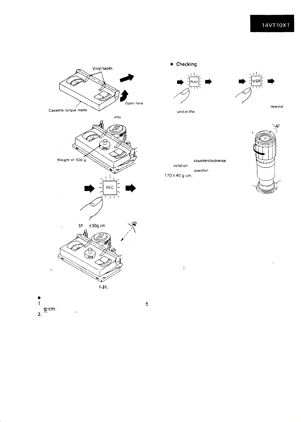
CHECKING AND ADJUSTMENT OF TAKE-UP
TORQUE IN PLAYBACK MODE
Remove the cassette housing control assembly.
1.
Open the lid of the cassette torque meter, and
2.
hold it with a pair of vinyl tapes.
CHECKING AND ADJUSTMENT OF TAKE-UP
TORQUE IN VIDEO SEARCH REWIND MODE
l
Remove the cassette housing control assembly.
Load a cassette torque meter
9
Set value SP 95 ?
30g.cm
Into
the unit
Push the play button to place Push the video
the
unit I” the
Place the torque gauge on the supply reel
disk, and turn it
lone
rotation
that the torque IS
170+40 g’cm.
playback mode. button to place the unit in the
counterclockwlse
every 2 to 3 seconds) and check
wlthln
the set value
video search rewind mode.
Torque gauge
very slowly
Supply reel disk
Figure l-32.
search rewmd
x;;>
CzY
Note:
Set the torque gauge securely on the supply reel
disk. If it is not secure, the measurement will be
incorrect.
l
Adjustment
Figure
1-31.
Checking
Check that the torque is in the range of 95 f 30
g-cm.
~.
&.
The toraue fluctuates due to the rotational
.~
deviation of the reel drive unit. Use the center of
the fluctuation as the value.
3. Place the unit in the SP record mode, and check
that the take-up torque is within the range.
l
Adjustment
If the take-up torque in the playback mode is
outside the range, replace the take-up reel disk.
Note: Weight the cassette torque meter to
prevent float.
If the take-up torque in video search rewind mode
is outside the range, replace the supply reel disk.
Note
:
The torque fluctuates due to the rotational
deviation of the supply reel disk. Use the center of
the fluctuation at the value.
19
Page 18
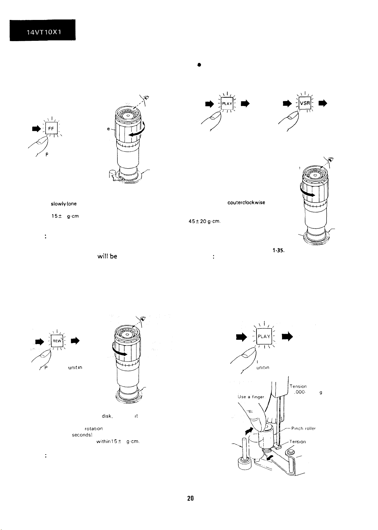
CHECKING THE FAST FORWARD BACK
CHECKING THE VIDEO SEARCH REWIND
TENSION BACK TENSION
l
Remove the cassette housing control assembly.
l
Checking
@
Remove the cassette housing control assembly.
l
Checking
‘I I\’
e :h’I
4
9
Note
*Torque gaug
‘I I\’
Place the unit in the
fast forward mode.
Place the torque gauge on the supply
reek disk, and turn it clockwise very
slowly (one
and check that the torque is within
152
rotation every 2 to 3 seconds)
5 g.cm
Figure l-33.
:
Supply reel disk
Set the torque gauge securely on the supply reel
disk. If the torque gauge is not securely set on the
reel disk, measurement
will‘be
incorrect.
CHECKING THE REWIND BACK TENSION
l
Remove the cassette housing control assembly.
l
Checking
3
Push the play button to place
the unit in the playback mode. button to place the unit in the
Place the torque gauge on the take-up reel
disk, and turn it
(one rotation every 2 to 3 seconds) and check
that the torque is within the set value
455 20
g.cm.
Note
couterclockwise
Take-up reel disk
Figure
:
4
Push the video search rewind
video search rewind mode.
Torque gauge
very slowly
u
kzh
l-35.
Set the torque gauge securely on the take-up reel
disk. If it is not secure, the measurement will be
incorrect.
CHECKING THE PINCH ROLLER PRESSURE
l
Remove the cassette housing control assembly.
Note
Place the
/
rewind mode.
:
unit
In the
Place the torque gauge on the
take-up reel
counterclockwise very slowly
(one
seconds)
torque is
disk.
and turn It
rotation
every 2 to 3
and check that the
wlthin 152
Figure l-34.
5
g’cm.
Take-up reel disk
Set the torque gauge securely on the take-up reel
disk. If it is not secure, the measurement will be
incorrect.
Capstan shaft
Push the play button to place the
unit In the playback mode.
Tension gauge
1
.aoo-
1,200
g
soon
gauge adapter
Figure l-36.
Page 19
Detach the pinch roller from the capstan shaft.
1.
Set the tension gauge by hooking the tension
2.
gauge adapter onto the pinch roller shaft.
Gradually release the pressure to allow the pinch
3.
roller to touch the capstan shaft. When the
pinch roller just touches the capstan shaft, read
the indication on the gauge.
4.
Check that the reading of the tension gauge is in
the range of 1000 to 1200
g.
CHECKING AND ADJUSTMENT OF TENSION
POLE POSITION
l
Remove the cassette housing control assembly.
Vinyl tapes
* :&
Place the unit
the record mode.
*
I”
2. At the beginning of the tape (E-180), check that
the tension pole’s left side is aligned with the
supply impedance roller’s left side by sight.
3. Check that the end of the tape is neither curled
against the flange of the supply impedance
roller nor over it.
4. During the video search rewind mode with no
cassette tape in place, check that the supply
reel disk is free from the tension band.
l
Position adjustment (record mode)
When the tension pole is at the right of the supply
impedance roller’s center:
Untighten the tightening screw, and shift the tension band adjustment bracket in the direction of
the arrow using a tension band and plate adjusting
jig until it is in the set value range (left side). Then
secure it with the tightening screw.
I
Center
SUPPlY
Tension band
and plate
sung
Supply impedance roller
Tension pole
I
ensjon arm
utde roller A
G
Check the
Tenston band
and plate
adjusting 119
settlng
hole
lef-t
echanism chassts
(4
Video
cassette tape
(E-1
80)
Guide roller
B
Tenston band adjustment bracket
Figure l-38.
l
Position adjustment (record mode)
When the tension pole is at the left of the supply
impedance roller’s center:
Untighten the tightening screw, and shift the tension band adjustment bracket in the direction of
the arrow using a tension band and plate adjusting
jig until it is in the set value range (left side). Then
secure it with the tightening screw.
I
Supply Impedance roller
TensIon pole
adI1
3e
(b)
Figure l-37.
l
Checking
1.
The guide rollers (A, B) operate to bring the tape
outside the cassette tape and simultaneously the
tension pole moves to the left, loading the tape.
At that time (loading completed), check the
position of the tension pole.
21
Tenston band adjusrment bracket
/ -
Figure
1-39.
Supply reel
band
Page 20
CHECKING AND ADJUSTMENT OF RECORD
I
PLAYBACK BACK TENSION
l
Remove the cassette housing control assembly.
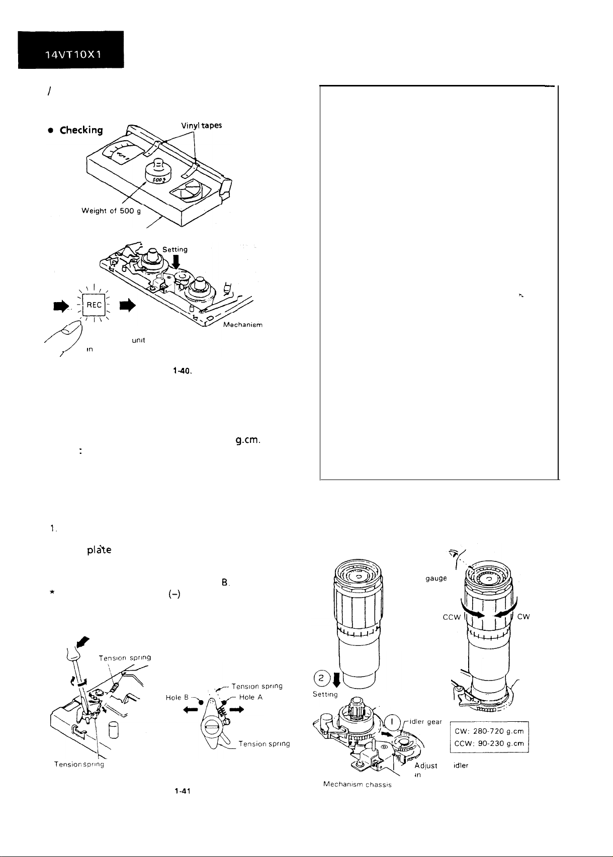
Open here
Cassette torque meter
Figure 142. Not used.
/
Push the record button
to place the
m
the record mode
unit
Figure
l-40.
chassis
1. Put a cassette torque meter into the unit.
2. Push the record button to place the unit in the
record mode.
3. Check that the back tension indicated by the
gauge is within the set range 31 to 36
Notes
:
g.cm.
1. Make sure that the video cassette tape is over
the retaining guide.
2. Make sure that the tape is not slack nor
damaged at either end.
l
Adjustment
1.
If the reading of the cassette torque meter is less
than specified, move the tip of the tension spring
hook
pIaYe
toward the hole A.
2. If the reading of the cassette torque meter is
more than specified, move the tip of the tension
spring hook plate toward the hole
*
Put a thin screw driver (-) in the shaft hole, lean
6.
it toward you, and turn it for easer shift of the
tension spring hook plate in the direction of A or
B.
CHECKING THE BRAKE TORQUE
l
Checking the brake torque at the supply side
Torque
gauge
/
LA
Tension spring
hook plate
Figure
1-41
Tenston spring
Tension swng
hook plate
Mechanism chassts
22
,-Supply reel disk
Adjust
in
the center
Figure
ti
-5:’
the Idler gear
143.
Supply reel
disk
--/
Page 21
1.
Remove the cassette housing control assembly.
2.
Place the mechanism in the stop mode by
unplugging the power cord in the fast forward
or rewind mode.
Slowly rotate the torque gauge in the clockwise
3.
(CW) direction and counterclockwise (CCW)
direction of the supply brake so that the reel disk
and the indicator of the torque gauge rotate at
an equal rate. Check that the values are within
the range of CW direction = 280 to 720
CCW direction
=
90 to 230
g-cm,
and that the
brake torque in the CW direction is at least twice
as high as that in the CCW direction.
0
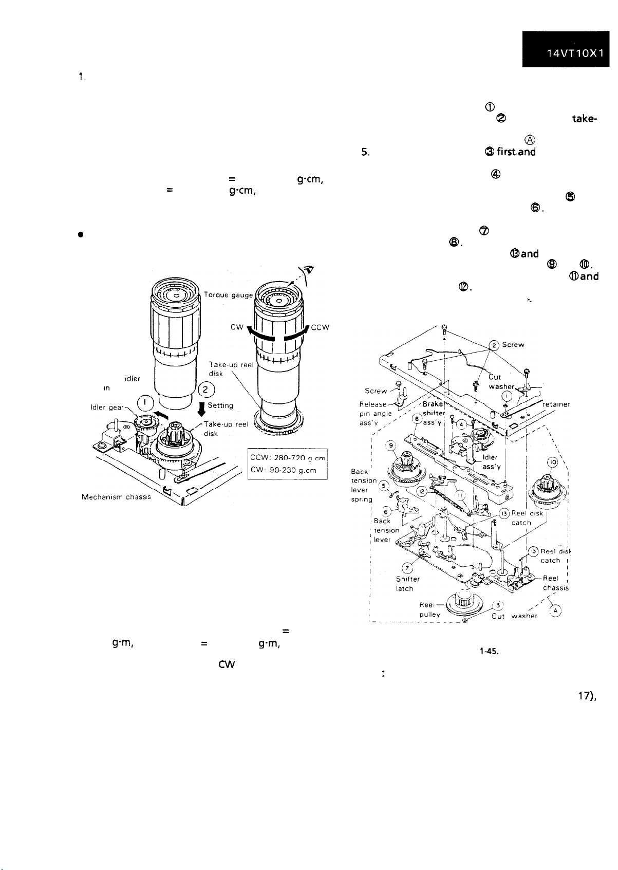
Checking the brake torque at the take-up side
g-cm,
REPLACEMENT OF MAIN BRAKE
1. Remove the reel belt and the reel block FFC.
2. Remove the cut washer 0 off the brake shifter.
3. Unscrew the four screws C3 and then the
take-
up reel retainer.
4. Remove the reel block assembly @ downward.
5.
Remove the cut washer 0
firstand
then the reel
pulley.
6. Unscrew the two screws @ and detach the idler
assembly.
7. Unhook the back tension lever spring
($9
and
remove the back tension lever @. (Undo the
hook under the reel chassis.)
8. Open the shifter latch 63 and remove the brake
shifter assembly
9. Release the reel disk catches
ED.
Oand
then remove
the left and right reel disk assemblies GD and
10. Finally remove the main brake levers
main brake spring
0.
@and
h
0.
Adjust the Idler
gear in the center.
Mechanism
1.
2.
chass
Figure l-44.
Remove the cassette housing control assembly.
Slowly rotate the torque gauge in the clockwise
(CW) direction and counterclockwise (CCW)
direction of the take-up brake so that the reel
disk and the indicator of the torque gauge
rotate at an equal rate. Check that the values
are within the range of CCW direction = 280 to
720
gem,
CW direction
=
90 to 230
g-m,
and that
the brake torque in the CCW direction is at least
twice as high as that in the CW direction.
l
Adjustment of the brake torque at the supply
side and the take-up side
1. If the supply or take-up brake torque is outside
the range, clean the supply or take-up reel disk
break lever felt, then recheck the torque.
2. If the supply or take-up brake torque is still
outside the range, replace the main brake or the
main brake spring.
Take-up
reel
retainer
Note
yqg wash/e;-
Figure
145.
:
3
Reel block ass’y
When the main brake is replaced, perform the
height checking and adjustment (see page
l7),
and the brake torque checking (see page 22).
23
Page 22
R&fCEMENT
Remove the cassette housing control assembly.
1.
Place the unit in the unloading mode, and
2.
unplug
0
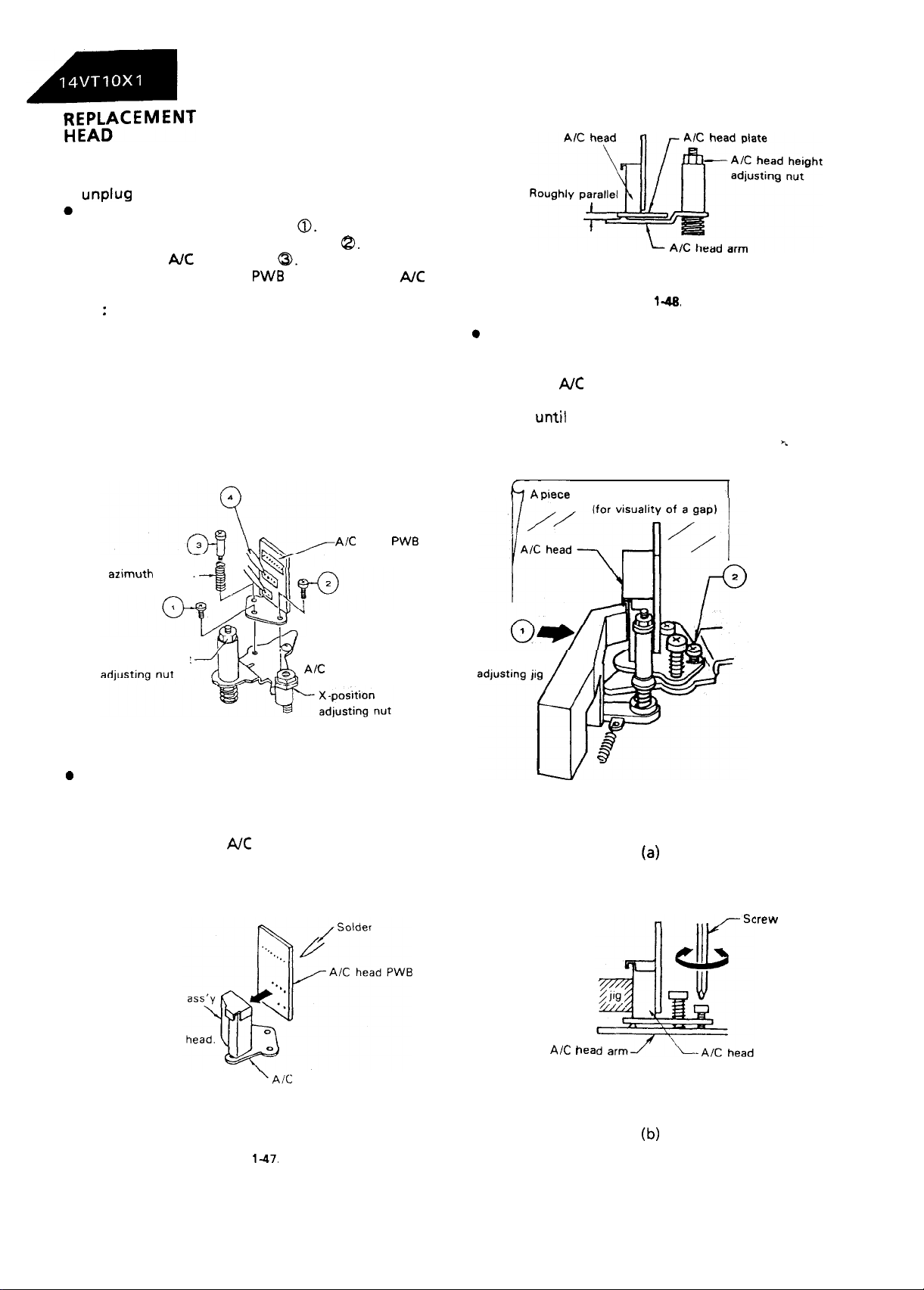
Removal
Loosen the tilt adjusting screw
1.
Remove the azimuth adjusting screw
2.
Remove the AK head screw
3.
Unsolder the A/C head
4.
the power cord.
OF A/C (Audio/Control)
0.
8.
a.
PWB
soldered to the
AK
head assembly.
Note
:
1. After replacement, be sure to perform the
adjustment of the tape drive train (see page 26).
Under any circumstances, avoid touching the
head. Clean the head, if touched with your
finger, with alcohol.
2. Take care that the azimuth spring does not fly
off when removing the NC head screw.
AK
head
PWB
Pay attention to
the azimuth spring.
Figure
14.
0
Adjustment
[A/C head tilt angle]
1. Set the mechanism to the loading mode.
2. Place the AK head tilt adjusting jig.
3. Slowly turn the tilt adjusting screw with a screw
driver
until
there is no gap between the jig and
the AJC head.
h -A
piecd of white paper
F.
Tilt adjusting
screw
A/C head height
0
Replacement
Figure 146.
AK
head arm
1. Solder the removed A/C head PWB onto a new
A/C head assembly.
2. The A/C head assembly is attached so that the
A/C head arm and AK head plate are roughly
parallel to each other.
New
A/C head
Never touch the
‘AK
head plate
A/C head tilt
A/C
tiea
I
(4
:rew
driver
Figure
1-47.
(b)
Figure l-49.
24
Page 23
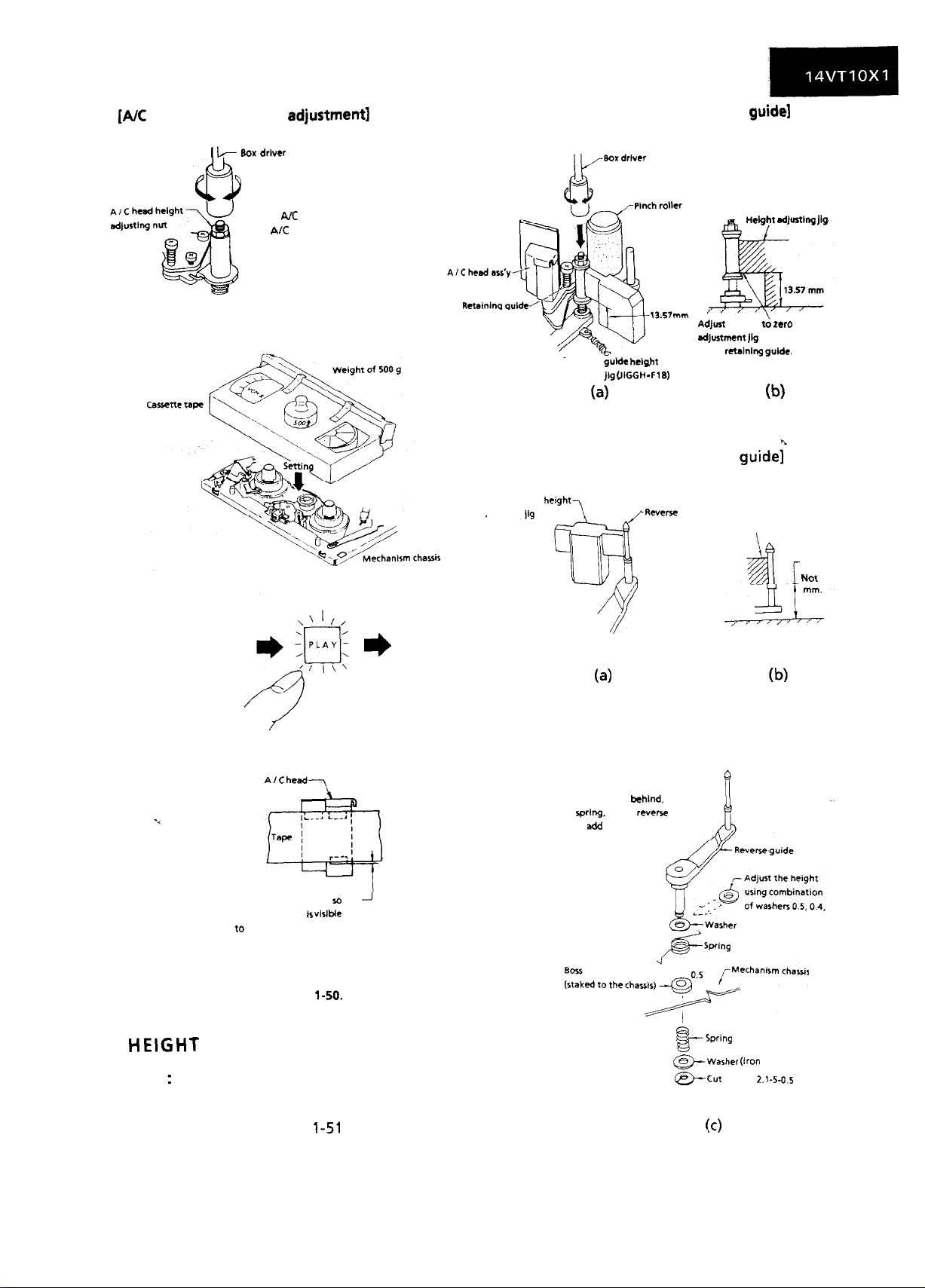
[AK
head height rough
1 k
adjustment)
80x driver
Roughly
adjust the height
of the AK head by turning
the AK head adjusting
hexagon nut with the
specialized box driver until
the tape is in the position
shown below.
[Height adjustment of retaining
AdJust
adjustment
Retaining
&de
adjusting Jg
height
(JiGGIl -
Fl8)
of the retainlnp
guide1
Hdght
the gap d zero between the
jig
(4
Figure l-51.
SdJurtlng
Jig
and the lower flange
guide.
(b)
A/C head-,
[Height adjustment of reverse
Reverse guide
adjusting jig
height?
(4
To readjust the height, remove
the cut washer from behind. take
out the
spring,
guide and
lift the reverse
sdd
a washer.
-Revewe
guide
guide;
Reverse guide height
adjusting jig
Go-end is 13.52 mm.
Not go-end is 13.38
(b)
Adjust the nut visually so that
the control head IS
to 0.5 mm below the bottom
of the tape.
Figure
visible
l-50.
J
0.3
HEIGHT ADJUSTMENT OF RETAINING
GUIDE AND REVERSE GUIDE
Note
:
Before the rough adjustment of the tape drive
train, check that the retaining guide height is
within the value in Figure
jigs.
1-51
by using the special
25
&-;arher
*Wing
-Spring
B
@-washer (iron
w Cut
washer
!d
Figure l-52.
0.25and0.13.
flat)
2.1-54.5
Page 24
ADJUSTMENT OF TAPE DRIVE TRAIN
1. Remove the cassette housing control assembly.
2. Check and adjust the position of the tension
pole. (See page 2 1.)
3. Check and adjust the video search rewind back
tension. (See page 20.)
4. Set the tilt angle of the A/C head. (See page 24.)
5. Rough adjustment of tape drive train.
a) Connect the oscilloscope to the test point for
PB CHROMA envelope output (TP501). Set the
synchronism of the oscilloscope to EXT. The
PB CHROMA signal is to be triggered by the
head switching pulse
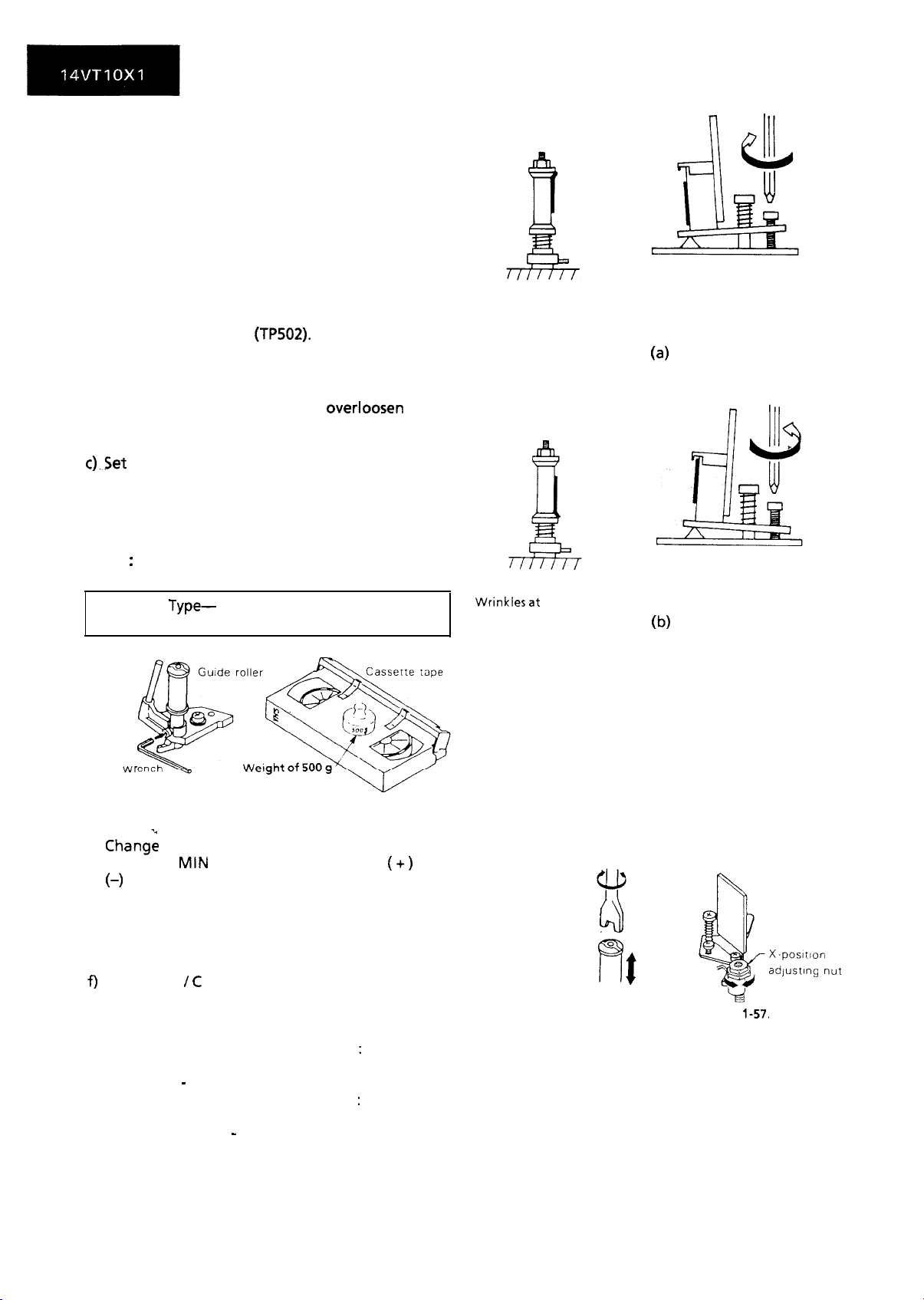
b) Loosen the setscrew at the lower part of the
guide roller, and adjust it with an adjusting
screw driver (JIGDRIVERH-4) so that the guide
roller turns smoothly. (Do not overloosen the
setscrew, which causes insecurity of the guide
roller.) (See Figure l-53.)
c).Set the alignment tape (See the Notes below)
on the reel disk, and place the unit in the
playback mode.
(Place a 500 g. weight on the cassette tape to
prevent floating of the cassette tape.)
Notes
:
1 Alignment tape.
2 Head
Type-
(TP502).
VROCPSV (PAL)
VROATSV (NTSC)
Wrinkles at upper flange
Wrinklesat
lower flange
Clockwise
(4
Counterclockwise
b)
Hexagon
d)
wr
Figure l-53.
Chang:
Figure l-54.
the envelope waveform from MAX to
MIN, and MIN to MAX by pushing the
(-) tracking button, and check a flat response
is obtained on the waveform.
e) If a flat response cannot be obtained, roughly
adjust the guide rollers on the supply side and
take-up side using an adjusting screw driver
until a flat response can be obtained.
f)
Turn the A / C head tilt adjusting screw with a
screwdriver to prevent the tape from
wrinkling at the upper and lower flanges of
the fixed guide.
1) Wrinkles at the upper flange : Turn the
above adjusting screw clockwise, as shown
in Fig. 1 - 55 (a)
2) Wrinkles at the lower flange : Turn the
above adjusting screw counterclockwise, as
shown in Fig. 1 - 55 (b)
(+)
or
Figure l-55.
Notes:
1. Place the tracking control in the center
position, and adjust the X-position
adjusting nut so that the PB CHROMA
envelop becomes maximum for easier
rough adjustment of the tape drive train.
2. In the rough adjustment, pay particular
attention to the outlet side.
Loosen theulsetscrew
Figure l-56.
Figure
1-57.
x-position
adjusting
nur
26
Page 25
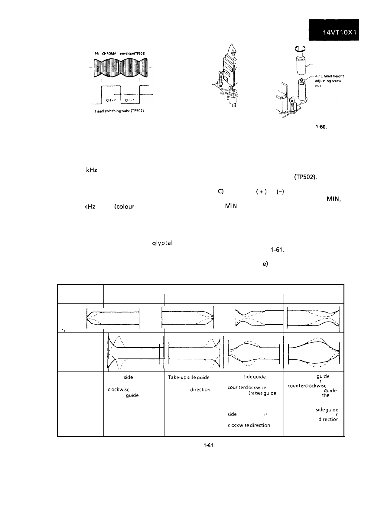
PB CHROMA l
nvel~f~
(TP501)
mad wnching pulse CTP502)
Figure l-58.
6. Adjustment of A/C head height and azimuth
a) Connect an oscilloscope to the audio output
terminal.
b) Use the alignment tape and play back its
audio 6
kHz
signal (monoscope pattern for
video signal). Adjust the azimuth adjusting
screw to obtain the maximum audio output
on an oscilloscope. (See Figure l-59.)
c) Use the alignment tape and play back its
audio 1
kHz
signal (colour bar for video signal)
and slowly rotate the A/C head height
adjusting nut with the special box driver to
obtain the maximum audio output.
d) Perform the adjustment in b) again.
e) After this adjustment, apply
glyptal
to the
screws and nuts to fix them.
i%
Box driver
Azimuth adjusting
screw
Figure l-59.
Figure
l-60.
7. Adjustment of tape drive train and X-Position.
a) Connect the oscilloscope to the test points
(TP501) for PB CHROMA envelope output. Set
the synchronism of the oscilloscope to EXT.
The PB CHROMA signal is to be triggered by
the head switching pulse
(TP502).
b) Play back the tape drive train alignment tape.
C)
Push the
envelope waveform from MAX to
(+)
or
(-)
button to change the
MIN,
MIN to MAX. Adjust the guide roller’s height
on the supply and take-up sides with an
adjusting screw driver, to obtain an envelop
waveform that is as flat as possible.
d) If the tape is above or below the helical lead,
the PB CHROMA waveform will take the shape
shown in Figure
1-61.
e) Adjust for maximum flatness of the envelope
as the step 5, e) in page 26.
and
4
kz/
Adjustment
When the tape is above the helical lead.
Supply side
Supply
stde
roller rotated in roller rotated in
clockwrse direction
(lowers gurde roller) to
flatten envelope
guide
Take-up side
it----y+
Take-upsrde gutde
clockwise dIrectron
(lowers guide roller) to
flatten envelope.
Figure
i-61.
When the tape is below the helical lead.
Supply side
%=&
Supply
roller rotated in
counterclockwtse
direction
roller) to make the
tape float above the
helical lead. The
srde
guide roller
then rotated in the
clockwrse
flatten the envelope.
side guide
(rarses
drrection to
gurde
supply
IS
Take-up side
it-y&j
Take-up side gurde
roller rotated
counterclockwlse
direction (raises
roller) to make
tape float above the
helical lead.
The take-up
roller is then rotated
the clockwise
to flatten the
envelope.
In
If
e
t
srde
gurde
directton
urde
rn
27
Page 26
f) Push the ( +) or (-) tracking button to check
that a flat response is obtained on the
envelope waveform.
g)
Secure the guide roller by tightening the
guide roller setscrew in the unloading mode.
h) Play back the tape drive train alignment tape
to check that the envelope waveform does
not change.
8. Adjustment of A/C head X-position.
Push the ( +) and (-) tracking buttons at the
a)
same time to the preset mode.
Rotate the X-position adjusting nut with an
b)
adjusting box driver, and adjust the A/C head
position for maximum head switching pulse
low side envelope.
Adjust the playback switching point.
d
d) Check the flatness of the envelope waveform
and sound by playing back a recorded tape.
X-posmon adlustfng nut
l-2mm
2!ilktk
Maw
Figure l-62.
II
chassis
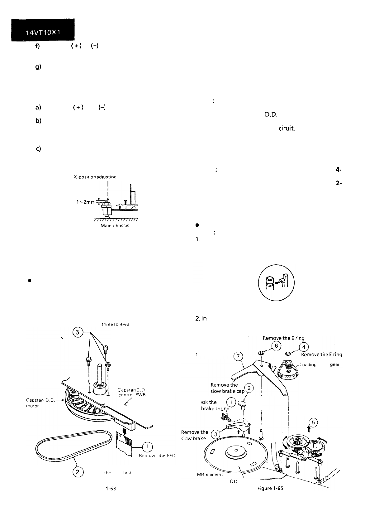
REPLACEMENT OF THE CAPSTAN D.D.
(DIRECT DRIVE) MOTOR
0
Remove the cassette housing control assembly.
l
Reassembly
1. Mount the capstan motor on the mechanism
chassis making sure not to allow the capstan
shaft to hit the mechanism chassis, and attach it
with the three screws.
2. Insert the FFC into the capstan D.D. motor
control PWB.
3. Attach the reel belt.
Notes
:
1.
After installing the capstan D.D. motor, be sure
to rotate the capstan
D.D.
motor and check the
movement.
2.
Check and adjust the servo
ciruit.
REMOVAL AND REASSEMBLY OF THE
LOADING GEAR BLOCK
Notes : The following explanation is based on
head models. (The slow brake spring and
slow brake lever are not provide&on
head models.)
1. Remove the cassette housing control assembly.
2. Remove the reel belt.
3. Remove the reel block.
0
Removal
Notes
:
Use care not to deform the parts hooked to the
slow brake shaft cap, take-up loading gear, and
supply loading gear as shown in Figure l-64.
42-
l
Removal (Follow the order of indicated
numbers.)
Remove the
2
Remove Ihe reel belt
0
Figure
Three
screws
Capsran D.D motor
l-63
L. In
roller with a rubber band or the like beforehand
for easier reassembly.
Remove the relay
gear drive lever
Unhook the
slow
brakesorinp 6
28
Figure l-64.
removing the loading gear, secure the guide
.Loadlng relay
Loading relay gear
Capstan D D motor
Page 27
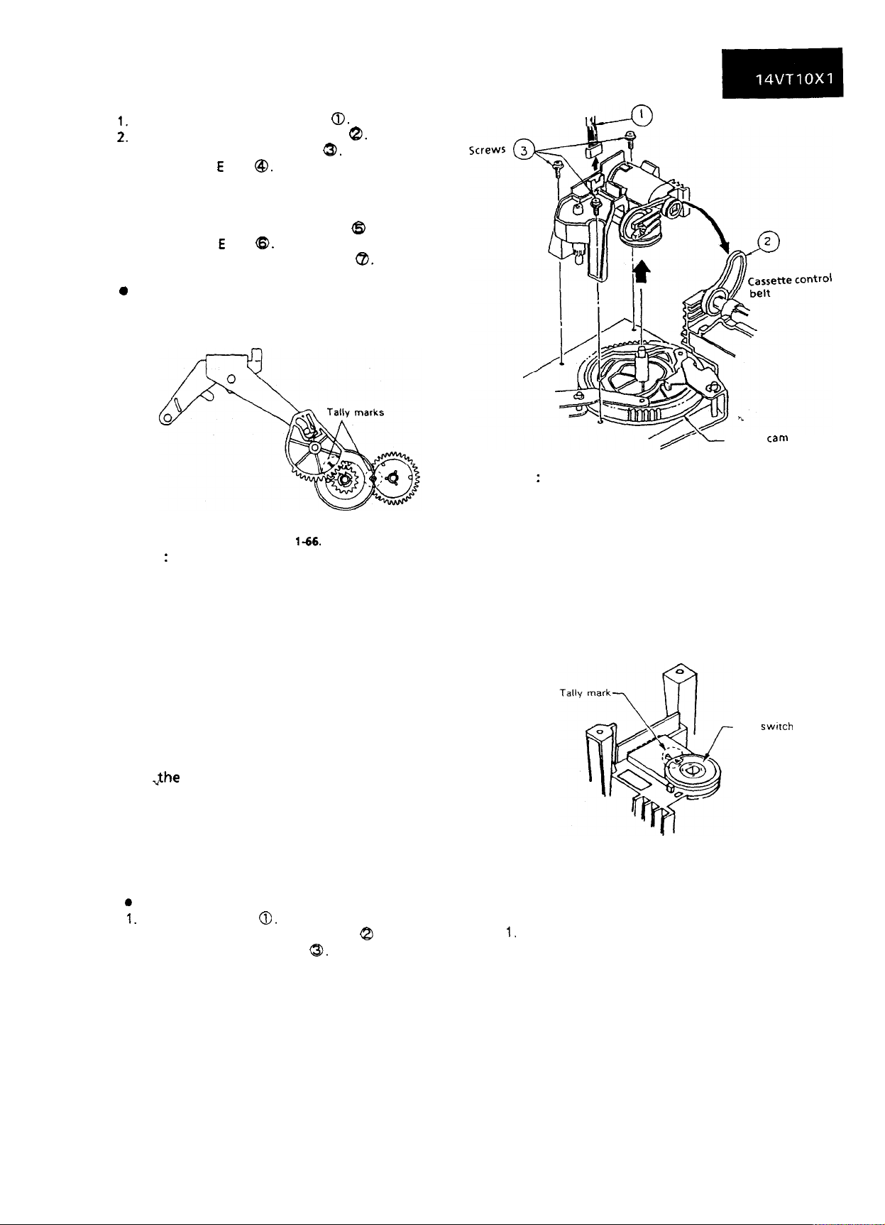
Remove the slow brake spring
Remove the slow brake shaft cap
::
Remove the slow brake lever
3.
Remove the E ring
4.
Rotate the take-up loading gear, take-up
5.
@.
0.
8.
a.
loading arm assembly, supply loading gear and
supply loading arm assembly slightly in the
loading direction, and take them @ all out.
Remove the E ring
6.
Remove the relay gear drive lever
7.
0
Reassembly
a.
a.
Reverse the procedure. Be sure to match the
tally marks on the gears.
Figure 1-66.
Notes
:
1. When reassembling, apply specified grease to
the following points; all the gear teeth, all the
gear shafts and the cam groove of loading
relay gear.
2. Be careful not the deform the supply/take-up
loading arms.
3. Be careful to keep clean the slow brake lever
felt.
4. Be also careful to keep the outer surface of
the capstan D.D. motor free from dust and
dirt. (If stained, the MR (Magnet Resistor)
element might be damaged.)
5. Take care not to deform the anti-fall hooks of
,the
slow brake shaft cap and supply/take-up
loading gears more than required.
Note
,&
:
Leads
Figure l-67.
Master
Can)
When using a magnetic screw driver in removal
of three screws, do not allow the magnetic driver
to hit the A/C head or drums.
l
Reassembly
1. Turn the master cam all the way counterclockwise.
2. Match the tally mark on the cam switch with the
mating mark. Fit the loading block and the
master cam
three screws.
with
each other. Tighten up the
Cam
swnch
REMOVAL AND REASSEMBLY OF LOADING
BLOCK
0
Removal
leads
1.
Remove the
2.
Remove the
3. Unscrew the three screws
4. Pull the loading
0.
cassette loading
a.
block upward.
belt
8
29
Figure l-68.
3. Finally connect the leads and apply the cassette
loading belt.
Notes:
1.
Be careful not to scratch the gear.
2. Be careful not to stain the belt. If dirty, clean it
up
with the specified
cleaning liquid.
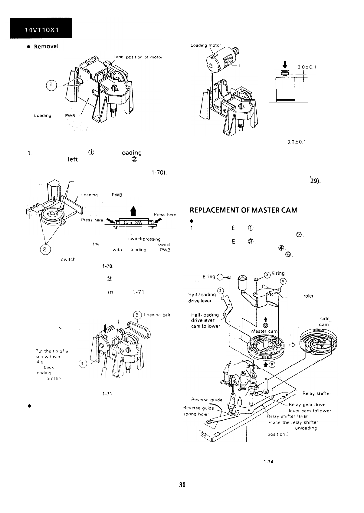
REPLACEMENT OF LOADING MOTOR
1. Set the cassette ejected condition by placing the
unit in the cassette eject mode.
2. Unplug the power cord.
3. Remove the loading block in accordance with
the statements and drawings above.
Page 28
Solder
I
o-
Unsolder here
Label
Loadmg
block
Figure l-69.
1.
Unsolder the leads 0 from the lpading motor.
2. Unlock the
left
and right catches
8
of the cam
switch off the loading block. Take out the cam
switch and loading block
Tally marks
,-Loading
2
8
Catches of cam
3. Take out the loading belt
4. Pry up the back end of the loading motor with a
screw driver or the like as In Figure
out the motor.
swttch
Figure
PWB (See Figure
block
PWB
Pull up the cam
the
catches Remove the cam SWliCh
together
with
the
switch pressmg
loading
l-70).
block
l-70.
C9.
1-71
and take
PWB
Note:
Figure l-72.
When press-fitting
motor pulley, keep the pressure
less than 5 kg, and the gap
between the motor and pulley
should be
Figure l-73.
3.020.1
the loading
mm.
3. Set the loading block PWB and the cam switch in
position.
4. Resolder the leads to the loading motor.
5. Finally place the loading block (See page
29).
6. Attach the loading belt.
REPLACEMENT OF MASTER CAM
0
Removal
1.
Remove the E ring
2. Remove the half-loading drive lever
3. Remove the E ring
4. Remove the pinch roller lever
5. Pull out the master cam upward
0.
@.
8.
@I.
6).
Pinch roller lever
Pinch
cam follower
roler
level
Motor label
Pa.,1 the :tp oi d
screwdrwcr
ilhe here Pry up
the
loadlny
take
0
Reassembly
1.
Remove the loading motor, and mount a new
baLk
end of the
motor and
nut the
or the
motor
Figure
l-71.
3
0
Loadq heir
I
loading motor as in Figure l-72.
2. Place the loading motor so that its label is visible
as shown in Figure l-72. Make sure that the
screw hole at the motor shaft, protuberance on
the loading block, and the motor’s back end
marked with the arrow are mated with each
other.
Enters the outermost
cam groove
30
lever to the
poslllon.~
Slow brake lever cam follower
Figure
l-74
Bottom side of
master
cam follower
unloading
cam-.
Page 29
Reassembly
Place the relay gear drive lever in the unloading
state.
Place the relay shifter so that it is in contact with
the reverse guide spring hole in the mechanism
chassis. Release the slow brake lever with a
finger to bring it away from the capstan (in the
direction of arrow). Then place the master cam
so that the D cut-off part of the master cam faces
the direction of arrow.
a,
Place the half- loading recipro lever’s cam
follower so that it fits in the master cam’s
circumferential cam groove (marked with
arrow), attach the E ring, then mount the half-
loading recipro lever.
4. Turn the master cam somewhat clockwise until
the pinch roller lever’s cam follower goes into
the master cam’s groove (marked with arrow).
Mount the pinch roller lever and then attach the
E
ring.
5. Rotate the master cam by hand to make sure all
~-
the four levers (relay gear drive lever,
half-
loading recipro lever, pinch roller lever, and relay
shifter lever) are in the cam grooves in place.
6. Mount the loading block.
Notes
:
(See
page 29.)
1. Be careful not to scratch the teeth and grooves
of the master cam.
2. After installation of the master cam, be sure to
rotate the master cam by hand before installing
the loading block. If the levers are in wrong
position, the master cam and the levers may get
damaged when the motor stares.
3. Apply specified grease to the master cam’s
grooves and teeth.
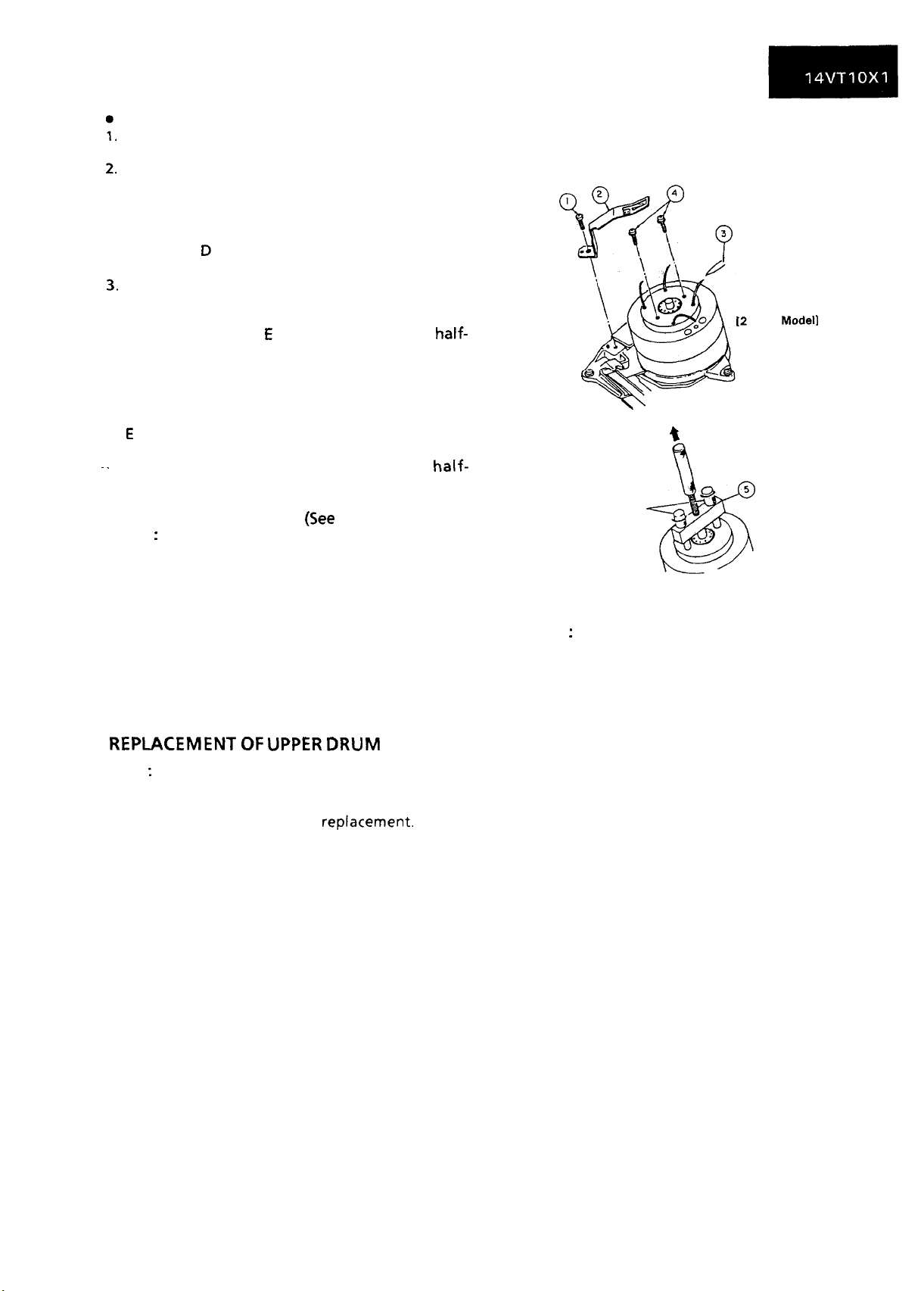
REPLACEMENT OF UPPER DRUM
Note
:
The gap between the lower drum and the upper
drum is very accurate, in the order of microns, and
care should be paid to their replacement. Even a
slight amount of foreign material will affect the
accuracy of their reassembly.
l
Replacement (Follow the order of the indicated
numbers.)
Unsolder the leads.
[2
Head Model1
*
Remove the upper drum by
pulling it with the upper
drum replacing jig.
Turn and tighten the
screws equally.
Figure l-75.
Notes
:
1. Avoid touching the drum surface with bare
hands.
2. Pull out the upper drum with care so that it may
not be tilted, and replace it with the upper drum
replacing jig using care not to damage the disk
circumference.
3. Do not hit the screws when tightening them.
31
Page 30
l
Reassembly
Notes :
1.
Before setting the drum, check that there are no
scratches or dust on the edge of the surface and
circumference of the disk.
2. Before setting the drum, check that there are no
scratches or dust on the internal surface and
edge of the surface of the upper drum.
3. On assembling these parts, insert the upper
drum onto the disk with care, so that the upper
drum is not tilted.
When assembling these parts, do not allow dust
4.
or dirt come between the disk and the upper
drum.
Do not use excessive force when driving in the
5.
screws.
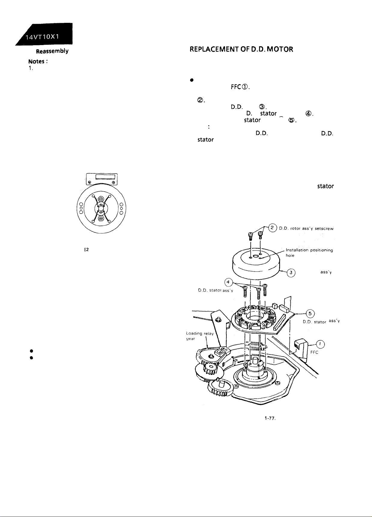
REPLACEMENT OF
Put the unit in the cassette eject position.
1.
Unplug the power cord.
2.
0
Removal (Reverse the order in reassembly.)
Remove the
1.
Remove the two D.D. rotor assembly setscrews
2.
FFC 0.
D.D.
MOTOR
8.
Pull out the
3.
Remove the three D. D.
4.
5. Remove the D.D.
Notes
:
When removing the
1.
stator
assembly, use care not to hit the loading
D.D.
rotor
stator
@,.
stator
setscrews
assembly
D.D.
Q.
rotor assembly or
@.
relay gear.
2.
Secure the D.D. rotor assembly so that the
installation positioning holes in the D.D. rotor
assembly and lower drum assembly match.
Be careful not to damage the upper drum or the
3.
video head.
4.
Be sure that the hall device and the D.D.
assembly are not damaged by the D.D. rotor
assembly or other parts.
After installation, adjust the playback switching
5.
point.
D.D.
stator
I2
Head Model]
Figure l-76.
1.
Set the new drum.
2.
Fasten the upper drum in place with the two
screws.
3.
Solder the leads.
Note: Soldering should be performed quickly
and carefully without touching adjacent
patterns.
4.
After replacement, be sure to check the tape
drive train adjustment (see page 26.) and the
following electric adjustments.
Adjustment of the playback switching point.
Checking and adjustment of the X-position
D.D.
stator
setscrew
Figure 1-77.
D.D. rotor
ass’y
ass’y
32
Page 31

REPLACING THE AHC
CLEANER)
(AUTOMATIC HEAD
Figure
l-78.
0
Removal
1. Unhook part 0 with a finger in the direction of
arrow.
Holir the rib (marked with an arrow) of the AHC
ass’y 8 with electrician’s pliers or the like, and
pull the ass’y upward in the direction of arrow
0.
Note:
To pull out the AHC ass’y, hold the AHC lever down.
l
Reassembly
1. Push down the AHC ass’y in the direction of arrow @. Make sure that the ass’y is secured in po-
sition by the hook of part
0.
Notes:
1. Be careful to keep the AHC ass’y out of contact
with the drum.
2. Be careful to keep the cleaner section of the ass’y
free of grease or contaminants.
33
Page 32

ADJUSTMENT OF THE VCR ELECTRICAL CIRCUITRY
Prior to the adjustment:
In most cases, necessity for electrical circuits will
arise from replacement of mechanical parts
including the video head.
adjustment of electrical circuits, check that
mechanical operation of the equipment is
complete (the mechanism are adjusted completely).
0
Instruments
l
VTVM
l
DC regulated power supply
ADJUSTMENT OF POWER CIRCUIT
l
Test points layout
Before starting
l
Oscilloscope
l
Audio generator
If the equipment fails electrically, locate a defect or
defects first of all using instruments. Then repair or
replace parts and make adjustment by the
procedures described below.
When required instruments are not available, do
not move controls indiscriminately.
l
Colour bar generator l Frequency counter
l
Alignment tape
0
Blank video tape (VHS)
n
ADJUSTMENT OF POWER CIRCUIT
Adjustment of power circuit
(AT6.5V)
1
Measuring
instrument
Mode
Test point
Control
Specification
(1) Connect a voltmeter to
connector PA) and ground.
(2) Adjust
R917
DC voltmeter
E-E
C921 $ LEAD
R917
8.W +
0.2
C921$
so that the voltmeter reads
(pin 4 of
8.5V.
Figure 2-O.
Adjustment of power circuit
Measuring
instrument
Mode
I
Test point
I
Control
I
Specification
(1) Connect a voltmeter to C919@ (pin 1 of
(2) Adjust R921 so that the voltmeter reads
(9V)
DC voltmeter
I
1
E-E
C919@
R921
9.4V 2
LEAD
0.1
I
I
connector PA) and ground.
I
I
I
9.4V.
34
Page 33

ADJUSTMENT OF SYSTEM CONTROUSERVO CIRCUIT
l
Test points layout
Figure
2-1.
SYSTEM CONTROUSERVO
-.W
ADJUSTMENT OF SERVO CIRCUIT
Adjustment of PAL System playback switching
point
Measuring
instrument
Mode
Oscilloscope
Playback
(tracking at center)
Tape used
Test point
Alignment
tape(VROCPSV)
CH-1; TP502
CH-2; Pin 8 of
IC201
(video
output). (CH-1 trigger slope
switch at ( + ), internal trigger at
CH-1 side)
PWB
Adjustment of NTSC System
point
Measuring
instrument
Mode
Oscilloscope
Playback
(tracking at center)
Tape used
Test point
Alignment
CH-1 ; TP502
CH-2; Pin 8 of
output). (CH-1 trigger slope
switch at (+ ), Internal trigger at
CH-1 side)
Control
R753
(60Hz
playbaik
switching
tape(VROATSV)
lC201
(video
SW. P. ADJ.)
Control
Specification
R751
6.5 2
(50Hz
SW. P. ADJ.)
0.5H
7.
1. Insert the PAL system alignment tape (VROCPSV)
and put the unit in the playback mode.
2. Press both tracking control button at the same
time to set the tracking in center.
3. Adjust
R751
(50Hz SW. P. ADJ.) so that the
waveform on the oscilloscope screen be as
shown in Figure 2-2.
w-2
(Video output)
CH-1
ediv
CH-2;
lV/div
50
pseddiv
Figure 2-2.
Specification
6.5 2
0.5H
1. Insert the NTSC system alignment tape
(VROATSV) and put the unit in the playback
mode.
2. Press both tracking control button at the same
time to set the tracking in center.
3. Adjust R753 (60Hz SW. P. ADJ.) so that the
waveform on the oscilloscope screen be as
shown in Figure 2-3.
CH-2
(Video output)
CH-1
ediv
CH-2; lV/div
Figure 2-3.
50
pseddiv
35
Page 34

Adjustment of PAL System slow tracking
Adjustment of PAL System still picture vertical sync
Measuring
instrument
Mode
Input signal
Test point
Adjusting point
Specification
1.
Play back the self-recorded tape in the PAL
System slow mode.
2. Make the resistor R1058 and R1060
circuited with diode in the timer PWB.
(Cathode of the diode is in R1060 side)
3. Be sure that the PB mode display
on-the screen.
4. Remove the short-circuit.
5. Adjust the tracking control using the TRACKING
button on the main unit or the remote controller
so that there is no noise on the screen.
Adjustment of NTSC System slow tracking
Measuring
instrument
Mode
I
Monitor TV
Recording and playback on
recording tape.
Commercial broadcast or video
signal.
Monitor screen
Tracking control button
No noise bar on the monitor TV
screen.
(b)
Monitor TV
I
I
1
Recording and playback on
1
recording tape.
Commercial broadcast or video
self-
(+),( -)
short-
disappears
self-
Measuring
instrument
Mode
Input signal
Test point
Adjusting point Tracking control button
Specification No noise jitter
1. Play back the self-recorded tape in the PAL
System still mode.
2. Using the TRACKING button on the main unit or
the remode controller, make adjustment so that
jitter becomes minimum.
3. Now press the STOP button to stop the tape.
Adjustment of NTSC System still picture
sync
Measuring
instrument
Mode
I
Input signal
Test point
Adjusting point Tracking control button ( + ),( -
I
Specification No noise jitter
1. Play back the self-recorded tape in the NTSC
System still mode.
2. Using the TRACKING button on the main unit or
the remode controller, make adjustment so that
jitter becomes minimum.
3. Now press the STOP button to stop the tape.
Monitor TV
Still
oicture
1
Self-recording tape
onitor
IM
Monitor TV
Still picture playback
I
Self-recording tape
Monitor screen
plavback
screen,
I
I
(+),( -)
vet&al
I
)
I
Specification
1. Play back the self-recorded tape in the NTSC
System slow mode.
2. Make the resistor R1058 and R1060
circuited with diode in the timer PWB.
(Cathode of the diode is in R1060 side)
3. Be sure that the PB mode display
on the screen.
4. Remove the short-circuit.
5. Adjust the tracking control using the TRACKING
button on the main unit or the remote controller
so that there is no noise on the screen.
No noise bar on the monitor TV
screen.
short-
(b)
disappears
36
Page 35

ADJUSTMENT OF Y/C CIRCUIT
l
Test point layout
Figure 2-4.
n
ADJUSTMENT OF Y/C CIRCUIT
Adjustment of EE level
f
Measuring
instrument
Mode
Input signal
I
Oscilloscope
I
Recording
Standard colour bar
(stair-case waveform)
Test point
Adjusting point
Specification
Pin 8 of
IC201
(video output)
R202 (EE level control)
2.0 + O.lVp-p (not terminated)
1. Set the unit in record mode.
2. Feed the colour bar signal to the video input
terminal. Observe the voltage of pin 8 of ~201
on the oscilloscope screen, adjust R202 (EE level
control) to obtain the value indicated in Figure 2-
5.
Y/C
PWB
Adjustment of white clip
Measuring
instrument
Mode
Input signal
Oscilloscope
I
Recording
Standard colour bar
(stair-case waveform)
1
Test point
Adjusting point
Specification
1.
Place the unit to the record mode.
2.
Feed the colour bar signal to the video input
1
TP201
R232 (white clip control)
80+4%
terminal
3.
Turn R227 clockwise to maximum position.
4.
Observing the output at
TP201,
adjust R232
(white clip control) so that the white peak
overshoot be 80 + 4%.
5.
Make sure that the dark peak overshoot is 50
10%.
.
2
Figure 2-5.
37
DARK
CLIP
50%
z-l
2Opseddiv
Figure 2-6.
Page 36

Adiustment of FM 3.8 MHz and 4.8
M
HZ
Measuring
instrument
Mode
Frequency
counter
Recording
Osci I
loscope
Self-recording/
plavback
I I
1
Adjusting
point
R227 (FM
carrier control) control)
Specification 3.8 2.0 +
Note
MHz +
:
50kHz
Carry out this adjustment only when
beenreplaced
or when the carrier setting (3.8 MHz)
.
R228 (Deviation
O.O8Vp-p
IC201
has
or the deviation (4.8 MHz) is found apparently out
of specification.
Make this adjustment after the EE level has been
completely adjusted.
1. First make sure that the EE video signal level is at
the specified level.
2. Place the unit in the record mode and get it
ready for external input.
Note
:
Do not connect anything to the external input
terminal.
3. Hook up the frequency counter to TP205 and
TP202. Adjust R227 (FM carrier control) so that
the counter reading be 3.8 MHz.
Note
:
Make sure the white clip control is not now
applied to the waveform.
4. Feed the
colour
bar signal and make
self-
recording and playback.
5. Observe the voltage of pin @ of
IC201
(video
output) on the oscilloscope screen. If the
playback video signal level is above 2.0 Vp-p,
turn R228 (deviation control) clockwise.
If below 2.0 Vp-p, turn the control counter-
clockwise. Now make self-recording and
playback again.
6. Repeat the above step 5 to finally get the
playback video signal level at 2.0 2 0.08 Vp-p, as
shown in Figure 2-7.
t
z.ovp-p
--
1
Figure 2-7.
Adjustment of recording current
Measuring
instrument
Mode
Input signal
Osci I
loscope
I
Recording
Standard colour bar
h
(stair-case waveform)
Test point
TP301
(GND at TP302)
External trigger
(video output terminal)
Adjusting
point
Specifica-
tion
R255
(recording FM
control)
Sync tip level:
R518
(recording
chroma control)
Red level:
140 + IOmVp-p 24 + ZmVp-p
Note:
TP301
and TP302 are located on the head amp
PWB.
1.
Place the unit to the record mode.
2. Feed the colour bar signal to the video input
terminal.
3. Observing the waveform on the oscilloscope
screen (external trigger at pin 8 of
IC201
(video-
output)), take the following steps.
a) Connect the oscilloscope’s ground and signal
leads to TP302 and
b)Turn
R255 (recording FM control) to min-
TP301,
respectively.
imum.
c) Adjust
R518
(recording chroma control) so
that the red level be 24 + ZmVp-p as shown in
Figure 2-9.
4. Adjust R255 (recording FM control) so that the
sync tip be
140 t
IOmVp-p as shown in Figure
2-10.
38
Page 37

Adiustment of delav level
Figure 2-9.
5OmVIdiv
I Opseci’div
Figure
2-10.
H
ADJUSTMENT OF Y/C PLAYBACK
CIRCUIT
Measuring
instrument
Adj usti ng point R240 (delay level control)
Specification
1. Insert the alignment tape and play it.
2. Adjust R240 (delay level control) so that the
levels of CH-I and CH-2 are the same as shown in
Figure 2-12.
CH-2
Dual-beam oscilloscope
CH-2 level = CH-I level
I
10 pseddiv
Adjustment of playback video signal level
,
Measuring
instrument
Mode
Tape used
r
Test point
Adjusting point
Specification
1. Insert the alignment tape and place the unit to
the playback mode.
2. Hook up the oscilloscope to pin 8 of
(video output) .
control) so that the on-screen waveform be
2.0 + 0.
IVp-p
Oscilloscope
I
I
1
Plavback
Alignment tape (VROCPSV)
(stair-case waveform)
I .
Pin 8 of
R209 (playback level control)
2.0 +- O.lVp-p (not terminated)
Adjust R209 (playback level
as shown in Figure 2-l 1.
IC201
(video output)
z.ovp-p
IC201
1
I
Adjustment of the APC (PAL)
I
Measuring
instrument
Mode
Tape used
Test point
Adjusting point C514
I Specification
1.
Inset-t
the alignment tape and place the unit to
the playback mode.
2. Connect the frequency counter to TP504. Adjust
C514 (APC control) so that the counter reading
be 4.433619MHz +
Figure 2-12.
I
Frequency counter
Playback
Alignment tape (VROCPSV)
(stair-case waveform)
TP504
(APC
control)
1
4.433619MHz f
20Hz.
2OHz
.~
I
Figure 2-l
1.
39
Page 38

djustment of the APC
Measuring
instrument
I
Mode
Tape used
Test point
Adjusting point
Specification
1. Insert the alignment tape and place,the unit to
the playback mode.
2. Connect the frequency counter to TP504. Adjust
C518
(APC
control) so that the counter reading
be 3.579545MHz +
n
ADJUSTMENT OF AUDIO CIRCUIT
(NT%)
I
Frequency counter
I
Playback
Alignment tape (VROATSV)
(stair-case waveform)
TP504
C5
18
(APC
control)
1
3.579545MHz It
20Hz.
20Hz
Checking of erase voltage and oscillation
frequency
I
Measuring
instrument
Mode
Input signal
Test point
Adjusting point
Specification
1. Place the unit to the record mode.
2. Hook up the oscilloscope to both ends of the
erase head.
3. Make sure the erase voltage is over 40 Vp-p.
4. Be sure that the oscillation frequency is
70 5 5kHz.
Oscilloscope
Recording
Both ends of the full-erase head
Erase voltage; Over 40 Vp-p
Oscillation frequency; 70 fi 5
kHz
full-
‘L
Figure 2-13.
Adjustment<of
Measuring
instrument
Mode
Input signal
Test point
Adjusting point
Specification
1. Play back the alignment tape
signal).
2. Hook up the VTVM to the audio output terminal.
3. Adjust R610 (playback level control) so that the
output level be - 9 + 1
playback level
AUDIO
PWB
VTVM
Playback
Alignment tape
(VROATSV)
(1
-kHz
level control signal)
Audio output signal
R610 (playback level control)
-9tldBs
(I-kHz
level control
dBs.
5 Useddiv
Figure 2-14.
Adjustment of bias current
Measuring
instrument
Mode
Input signal
Test point
Adjusting point
Specification
1. Place the unit to the record mode.
2. Connect the VTVM to TP601 (SIG) and TP602
(GND).
3. Adjust R630 (bias current control) so that the bias
current be 260 t 1 OyA (2.6 + 0.1
VTVM
Recording
TP601 (SIG), TP602 (GND)
R630 (bias current control)
260 + 1
OuA
(2.6mV + 0.1
mV).
mV)
40
Page 39

Checking of recording level
Adjustment of the AFT
Measuring
instrument
Mode
Input signal
Test point
VTVM
Self-recording/playback
1
kHz/-8dBs
Audio output terminal
Control
Specification
1. Feed 1
kHz,
-8 2 3dBs
-8
dBs
signal to the audio input
terminal. Make self-recording and playback of
the signal.
2. Make sure the output at the audio output
terminal is - 8 f 3
3. If out of
~.
bias current.
H
ADJUSTMENT OF THE IF CIRCUIT
spec,
dBs.
readjust the playback level and the
Adjustment of the RF AGC
Measuring
instrument
Oscilloscope
Signal generator
PIF
Input signal
frequency uniwave
Colour bar signal (70 dBu)
Test point
Pin@of
IF Pack(GND)
Pin @ of IF Pack (Video Output)
Adjusting point
TOO2 (AFT coil)
Specification
1.
Receive the
strength: 70
2.
Using the signal generator, feed the
frequency
colour
dell).
(36.87SMHz)
bar signal (input field
signal (sinewave) to the
tuner IF output terminal.
3.
Set the tuning switch to the VHF or UHF position.
Keep the tuning button
(+)
or ( - ) depressed
until the beating on the oscilloscope screen be
minimum. .
4.
Set the tuning switch on the normal position.
Adjust TOO2 (AFT coil) so that beating on the
oscilloscope screen be minimum.
PIF
Mode
Input signal
Test point
EE
Colour bar signal
Pin@of
IF Pack(GND)
Pin @ of IF Pack (Video Output)
Adjusting point
1. Receive the
VROOl (AGC
colour
bar signal (input field
control)
strength: 80 dBu).
2. Observe the video output terminal waveform on
the oscilloscope. Adjust
VROOI (AGC
control) in
the IF pack until the noise disappears from the
oscilloscope screen and the waveform nearly
comes into sync.
Just
before shrtnking
RF AGC
AFT
IF Pack
Figure 2-15.
41
Page 40

l
Chassis layout
(K
IO041
540 I
& SEkSw
ADJUSTMENT OF THE TV ELECTRICAL CIRCUITRY
I
I!
I
I i-l
DL4OI/ j )
II
(K
IO031
CZI J-y----
-
/
AUDIO IN
ICE0 I
I
.LI
Figure
3-1.
Mother PWB
I
CRT
Q
R-BIAS
G-BIAS
I
B-BIAS
3
Figure 3-2. CRT Socket PWB
42
G-DRIVE
B-DRIVE
Page 41

VIDEOKHROMA ADJUSTMENT
CRT cut-off and Sub-Brightness adjustment
l
R853: R- bias control
l
R859: G- bias control
l
R865: B- bias control
l
R857: G-drive control
l
R863: B- drive control
Note:
Prior to this adjustment, warm up the unit with
the beam current of more than
than 30 minutes
Receive “MONOSCOPE PATTERN” signal with
1.
pattern generator.
Set R857 (G-driver control) at CENTER
2
position
Set R863 (B-driver
contol)
position.
Set R853
Set
(R-biascontrol)
R859
(G-bias control) at
at MIN
Set R865 (B-bias control) at MIN
Set the control at the “Normal” position that
3.
contrast is Max (15x15), colour is center
and brightness is center (7/15) using control,
Aand v
Set the screen control at MIN (O/l 0) position.
4.
Turn on
5.
line
Connect the oscilloscope to TP852 (Red
6.
keys.
5401
position.
(service switch) at the horizontal
cathode).
7.
Adjust the sub-brightness control (R425) so that
the blanking pulse on oscillosope is 10 + 1 Vp-p.
, ,
nFl”p-p
600uA
for more
at CENTER (5/10)
(O/10)
position.
MiN (O/l 0)
(O/IO)
position.
position.
(5110)
(7/l
5)
3.
Set the brightness control at MAX position.
4.
Connect beam ammeter to TP601 and TP602.
(Full scale: 3mA)
5. Adjust the sub-contrast control (R436) so that
the beam current becomes approx.
0.8mA
(rough adjustment).
6. Adjust the drive-control
(R857,
R863) so that the
colour temperature is at 7500°K. (High beam:
0.8mA)
7. Adjust the contrast control and brightness
control so that the beam current is about
200pA, and check that the colour temperature
is at 7500°K. If the temperature is not at
7500”K,
go back to “CRT cut-off adjustment” and repeat
the adjustment.
(X =
0.300,Y 5 0.310)
h
Sub-contrast control: R436
Note:
Prior to this adjustment, warm up the unit
with the beam current of more than
600uA
for more than 30 minutes.
Receive “MONOSCOPE PATTERN” signal with
1.
pattern generator.
Set the Contrast controls at MAX position.
2.
Set the brightness control at MAX
3.
Connect beam ammeter to TP601
4.
TP602
Adjust R436 so that the beam current becomes
5.
(+).
(Full scale: 3mA)
positin.
(-)
and
0.8mA.
8.
Slowly turn the screen control clockwise and
stop
it where the horizontal raster appears
slightly, in one of the three colours.
9.
Carefully adjust the vias controls of the other
two colours until the horizontal raster becomes
white.
lO.Turn the screen control counterclockwise until
the horizontal rester disappears, and stop it.
White balance/Back ground
0
R857: G-drive control
0
R863: B-drive control
l
R436: Sub-Contrast control
Note:
Prior to this adjustment, warm up the unit
with the beam current of more than
600).1A
for more than 30 minutes.
1. Receive “MONOSCOPE PATTERN” signal with
pattern generator.
2. Set the Contrast control and MAX position.
43
PAL
chroma
adjustment
Note:
Before this adjustment, the
PIF/AFT/AGC
adjustment must have been completed.
l
R806: 1 H-delay amp control
l
T801: 1
H-delay phase control
Receive “PAL COLOUR BAR” signal with colour
1.
bar generator.
Connect the following resistance matrix to
2.
pins 0 and @ of the connector
(K),
to which
an oscilloscope is connected.
To osci”‘z\t
;::53
(pin @ of
2;!f
Resistance Matrix
K)
Page 42

3. Set service switch
S401
at the Video Cut position
to cut off the Y signal.
4. Adjust the colour control key so that the output
waveform of colour difference signal becomes
1.5 vp-p.
5. Adjust R806 and T801 so that the output
waveform shown in Fig. a is corrected to that
shown in Fig. b.
6. Return
5401
to CENTER (normal position).
PAL
Sub-colour
adjustment: R802
1. Receive “PAL COLOUR BAR” signal with colour
bar
generator.
2. Set the control at the “Normal” position that
contrast is Max.
and brightness is center
(15/15),
colour is center (7/15)
(7115)
using control, A
and v keys.
3. Connect oscilloscope to the TP852 (Red cathode).
l
Range:
l
Sweep time:
2OVIdiv
2Opseddiv
4. For PAL colour bar signal reception, adjust R802
so that the white output (75%) and red output
will have the same level.
CY
Mg
a
G
Figure
a. Waveform before the adjustment
Figure b. Waveform after the adjustment
Sub tint: R882
1. Feed “NTSC COLOUR BAR” signal to video in jack
with colour bar generator at the AV mode.
2.
Connectoscilloscope
3. Set the TINT VR
to TP853 (B-Y).
(R1098)
at the center
(5110)
position.
4. Set service switch
5401
at
the Video Cut position
to cut off the Y signal.
5. Adjust colour control key to obtain the output of
about 3 Vp-p.
6. Adjust sub tint control (R882) so that the output
waveform is as shown in figure below.
7. Return
5401
to CENTER (normal position).
Y
w
Same level for the
R
whbte
and ted outputs
Same level-,
8-Y
*,-’
‘w Y
I
.
-
cv c
-
I
’
MQR B
1
/
-
,
,
,
I
Page 43

ADJUSTMENT OF
Note:
l
During the adjustment, keep the unit facing the
east.
DEFLEmON
LOOP
Focus adjustment
1. Receive “MONOSCOPE PATTERN” signal.
2. Set Contrast control at NORMAL position.
3. Set Brightness control at NORMAL position.
4. Adjust Focus control to have best focus at the
central area of CRT.
Adjust
point
Horizontal
* This adjustment should be performed after the
purity and convergence adjustments.
1. Receive “MONOSCOPE PATTERN” signal.
2. Adjust R602 so that the horizontal center of
picture is at the position which gives the relation
of A = B shown below.
centering
control: R602
Vertical linearity control: R526
1. Receive “MONOSCOPE PATTERN”
2. Adjust R526 so that the vertical linearity of
picture is at best point.
signal.
Vertical size control: R503
1.
Receive “MONOSCOPE PATTERN” signal.
2.
Set the Brightness control and Contrast control
at MAX position.
3.
Adjust R503 so that the vertical size of picture is
at the same size as horizontal size.
0
Vertical size: 9% TYP (Max. 11%)
Vertical centering control:
*
This adjustment should be performed after the
purity and convergence adjustments.
1. Receive “MONOSCOPE PATTERN” signal.
2. Adjust
identical to CRT geometrical vertical center.
5501
so that the picture’s vertical center is
5501
45
Page 44

PURITY ADJUSTMENT
Note:
l
During the adjustment, keep the unit facing the
east.
Purity
adjustment
1.
Prior to the purity adjustment, warm
with beam current of more than
up
the unit
500pA,
for
more than 30 minutes.
2. Receive the green signal alone and adjust the
beam current to about 500uA.
3. Fully degauss the CRT with the degaussing coil.
4. Before the purity adjustment, It is needed to
roughly adjust the static convergence.
5. Set the purity magnet
at
the position which gives
zero (0) magnetic field.
Adjustment:
6. Observe the green spots
microscope as shown in Fig.
purity magnet so that they are at the specified
landing position.
(“a”
and “b”) with a
3-3.,
and adjust the
The beam landing IS shlhed
to right.
Figure 3-5.
The beam landing IS shifted
to
kfl
Figure 3-6.
RlQht
Figure 3-3.
7. If the right and left green spots are both
deviated outwards from their landing positions
as shown in Fig. 3-4 push the deflection yoke
forwards until their positions are corrected.
Left
,
#
I
1
I
,
,
\
The beam landing is shifted
outwards.
Figure 3-4.
9. Adjust the purity magnet so that the beam
landing is correct at either of the centeral part,
right and left parts of screen, then check that
the green beams at four corners of screen are
all correctly positioned.
Finally, check that the beam landing at any pat
of screen is satisfactory with the Rank “B”
specifications.
10.
If the green beam is positioned to mix with the
other
colour,
pull the deflection yoke
backward.
l
Outside of the specified landing: To front of the
deflection yoke
l
Inside of the specified -landing: To back of the
deflection yoke
11.
Receive
“MONOSCOPE PATTERN” signal or
“CROSSHATCH PATTERN” signal.
12. Set the raster rotation at
“0”
position (with the
unit fasing the east.)
13. Tighten the screws of the deflection coil.
Tightening torque: 11 kg + 2kg
8. If the beam landing is shifted to right or to left as
shown in Figs. 3-5. and
3-6.,
adjust the opening
degree of the purity magnet so that the beam
landing is correctly positioned.
46
Page 45

CONVERGENCE ADJUSTMENT
Note:
l
During the adjustment, keep the unit facing the
east.
Convergence adjustment
This adjustment should be performed after the
purity magnet adjustment.
1.2.Receive crosshatch pattern signal with pattern
generator.
Set the Brightness control at CENTER position.
Set the Contrast control at MAX position.
Wedge
magner
/
CRT neck
J
-
\
I-pole
IIHI
Convergence in Fig. 3-8.:
Insert wedges
(b)
and
(c)
between the deflection
yoke and CRT, and tilt the deflection yoke
downward until the mis-convergence shown in
Fig. 3-9. is corrected.
RGB
I
I
I
Convergence in Fig.
Insert wedge
(c)
deeply between the deflection
!
Figure 3-8.
3-9.:
yoke and CRT, and tilt the deflection yoke to
right until the mis-convergence shown in Fig.
3-
9. is corrected.
T-l--b
Lacquer
0
Static Convergence
3.
Adjust the opening degree of the 4-pole magnet
and rotate the magnet to converge red and blue
lines.
4.
Adjust the opening degree of the 6-pole magnet
and rotate the magnet to converge red, blue and
green lines.
0
Dynamic convergence
c
2.
Dynamic convergence (convergence of the three
colour
fields) at the edges of CRT screen is
accomplished in the following manner.
l
Convergence in Fig. 3-7.:
Inset-t
wedge (a) between the deflection yoke
and CRT, and tilt the deflection yoke upward
until the mis-convergence shown in Fig. 3-7. is
corrected.
BGR
\I,
Figure 3-9.
Convergence in Fig. 3-l 0:
Insert wedge
(b)
deeply between the deflection
yoke and CRT, and tilt the deflection yoke to left
until the mis-convergence shown in Fig.
3-10
is
corrected.
I
Figure 3-10.
II ‘1
6. Stick the three wedges onto the CRT, and apply
glass tapes thereon.
7. Apply lacquer to the deflection yoke screw,
magnet unit (made of purity, 4-pole and 6-pole
magnets) and magnet unit screw.
I
I
Figure 3-7.
Blue signal and check that there is no mixture with
the other colour signal.
47
After the adjustment, receive either the Red or the
Page 46

CRT DISPLAY ADJUSTMENT
Note
:
l
During the adjustment, keep the unit facing the
east.
Sign position control:
1. Select channel
RlOOl
“2”.
2. Receive “CROSSHATCH PATTERN” signal.
3. Press the Mode OSD button on the Remote Controller.
4. Adjust
shown below.
5. After adjustment, confirm that there is no defect
in the on-screen characters with no signal and
AV
*
The error in the settlement of charactor position
must be
RlOOl
to obtain the sign position as
mode.
b>a.
a: the range of the error in the settlement
b: range between two crosshatch vertical lines
Ailgn
the right edge of channel
number with crosshatch’s
vertical line from right.
third
48
Page 47

TROUBLESHOOTING FLOWCHART
MECHANISM OPERATION FLOWCHART
*
CASSETTE
Cassette
inserting
Half-loadmg
INSERTION *STOP
I
Loading
and
master
I
Does cassette control clutch
wthin 2.5 I~C.
turned
Are start/end ~“sors at
before c7wette
Half-loading
tape.
This flowchwtdcwrikr the
not
give
For cam switch poritlons. se4 Fig.42
Insert UIIene.
1
Turn
off
cassette switch.
+
motor
staN in normal direction
cam clockwise.
+
after
off?
lever
Is cam switch at FF position?
Loading motorstop~.
tome off
cassette switch has
high level
insertion?
YES
workstodrawout
its
details.
outline
of
the mechmirm’s operation. but
I
Cassette isejected and loading motor
rtopr.
I
loading
and master cam counterclockwise.
1
(Cassette is judged caught
NO
(Cassette LED or some
judged defective.)
1
does
t
4
Cassette
switch
turns
on.
t
motor turns in reverse dwectlon
t t
halfway
)
other part
is
STOP +
REUPIAY
I
Press REOPLAV key.
I
Loading
motor
Es
turns in normal direction
I
1
I
Tape loadmg
Pole base works
Pinch
I
Is cam switch
I
1
I
Capstan
motor
todraw outtape.
roller
comes
intotontwt.
at PE
positto”?
t VES
t
Loading motor stops.
YES
turns in normal direction.
I
NO
I
I
I
Unloading
7
t
I
+
Picture appears
I
I
I
Page 48

PLAY +STILL
PLAY + VSR
VSR + PLAY
Slow
brake
prewng
Press STILL key.
Loading motor turns in normal directtlon
1 and
mestercam
1
Slow brake comes into contact
chx;!se.
with
End
Press REW key.
I
Pmch roller
relearmg
Idler
wmging
Loading motor turns in
and master am clockwise.
Is tern switch
Turn capstan motor m reverse dIrectIon
{
1
Turn loading
1
notmsldirection
at PU
posItion?
lNO’
YES
Stop loadmg
motor in
motor
1
I
reverse dvection. 1
I
I
Loading motor turns in reverse direction
and master cam counterclockwise.
Press PLAY key.
4
+
Set
capstan motor to pleybeck
I
speed
+
Pinch roller
prerrmg
I
Press pinch roller.
YES
1
PLAY -3
VSF
Set capstan motor to search speed
I
Stop loading
Set cspnan
I
t
motor to
+
i
motor.
search speed.
YES
NO
I
Unloading
1
Page 49

REC /PLAY + STOP
PressSTOP
I
key.
1
STOP
--B FNREW
1
Is
cam
witch
at FF
I
position7
N
l-4
Tape unloading
Brakelatching (9)
Stop capstan motor in
about 5 sec.
f
stop capstan motor.
.
I
Stop loading motor.
Turn capstan motor in
reverse direction.
NO
Check 1 : Is
Release brake solenoid and
brake reel disk.
Turn loading motor in
reversedirectmn.
Release brake taking steps
‘brake
Turn capnan motor in
normaldirection.
Check 2 :
t
Stop drum motor.
1
*
YES
1
t
take-up
reel
puke outputted?
t YES
stop capstan motor.
4
t
1
t
latching (‘1)‘.
t
t
Irtake-up
reel
pulseoutputted
$
YES
stopcapstan motor.
End
,pe
slack
detecting
I
End
l Z:Tape is judged to be
.
I
I
and
EJECT and
be accepted. First check
take-up
see
detector functions.
The
when the output is
specified. This is
taper
End ‘2
any other key-in than
reel
ifthe tape
tape is
agamst damage.
slack
POWERcannot
pulse
output to
slack
ejected only
as
to
protect
the
Press FF/REW key.
FFIREW
and
mastercam~ounterclockwae.
L
Turn loading motor in normal direction.
YES
End
rake latching
’ I
operation
iid
FF/REW -s
I
Brake function
:
STOP
Stopcapstan motor.
Release brake solenoid and brake reel
disk.
T
End
1
+
J
1
Page 50

STOP + CASSETTE EJECT
Preu
EJECT key.
Half-loading
bringing-back
lever
Stop Ioadmg
t
End
I
motor.
Fia.4-1
cam switch pattern
The cam switch has
4-l. The circuit turns on when the signal comes
on the shaded zones on
pattern
system controller in order
mechanism modes.
t
olete
Clutch
change
FFREW(STOP)
0
signals
Main brake
the pattern as
are
judged
l
shown in Fig.
the
witch. The six
to bc on or off by
to
detect
ncrgiied
LO PLAY VS.REy
Master
the
the
360’
cam
Pinch
turning
roller
activated
El
Fia.4-2
The relationship
I*’
Rclrtionrhip
bctwcen the
q
between tam
7
cam witch positions
” [yQLL
fipu
witch positions
Cam
and
rnd the
mechanism movement is
mechanism
switch
pattern
\
Tcrmin*l
movement
No.
*how” in
Fig 4 -2
Page 51

1. FFIREW
MECHANISM
FAILURE (NO TAPE WINDING)
TROUBLESHOOTlNG
YES
:
2.
1
REVPlAY
Is brake shifter at
PLAY
position?
FAILURE (MODE RELEASE)
Remove cassette
controller, turn
power on and press
PB key.
(REC)
1
YES
NQ
Brake shifter is
deformed.
Replace.
Is brake shifter at NO
-
PLAY position? - shifter.
1
YES
Replace relay
’ [yH?h
overloaded due to
damage on tape.
Damaged tape is
deformed. Replace
Check for broken NO Clean solenoid
solenoid lead (turn
power off,
disconnect FFC and
check with tester).broken
YES
I
[ Replacesolenoid.
v
-+
while attracted, or
replace it.
No
lead)
1
1
Are idler gear and
reel disk PB gear in
mesh?
L
NO
H
I
Replace idler
assembly.
I
L.
Is take-up reel disk
pulse outputted 1 - turnmg
YES
Check main PWB.
NO
Is capsten
Is 5V applied at
reel PWB
1
t
DD
YES
?
I
I
NO
AreVco
- “cc 5V
1
ReDplace
NO
12Vand NO
applied
2--t
YES
‘I
capstan
Disconnect and
reconnect main
FFC.
Page 52

3. WINDING FAILURE AT VSR
4. UNUSUAL SOUND IN EACH MODE
I
:
I
Remove cassette
controller, turn
power on and press
PLAY key.
Go to 2.
Istake-u normal NO
during p
Is
VSR
ayback ? -
P
YES
Press VSR key. (Turn
take-up reel disk by
hand.)
brake shifter at
position
?
1
NO
--j
FAILURE routine.
shifter.
REUPIAY
Replace brake
--T=---1
t
Does idler gear
I
YES
lssuppl
reel disk
rl
torque etween
140 and 200 g-cm?
I-
1
YES
--f
NO
Replace supply
reel disk.
Insert cassette and press PLAY
and STOP keys repeatedly.
Check for rattling
loading/unloading.
I
Isreeldiskheightas
specified (using jig)
I
I
,
Is
no unusual sound
heard at FF
‘14’“““‘*”
NO .
1
YES
ower
ON
FF
keY
IN
1
JFe?s
REW key and turn take-
h;q;&;ey.
Replace L block sub
“,~%?l)&!~ing
Re;ii;.st
t-l
I I
Turn take-up reel disk
slowly with finger.
NO
Are take-up reel
stopper and
rubbino
_I
block)
reel
drsk
‘ear
PB
5,
each ot er
?
1
I
h
1
NO
Replace take-up reel
stopper.
H
-1-,-
Is no unusual sound
heard at REW?
YES
r
F
t
I
/ $s$,%$$s%
R Replacecapstan
DD.
If there is no unusual
sound heard again
each mode, go back to
the start of routine to
recheck.
in
Page 53

Unplug
the
AC
Replug it a
Is the
fuse resistor R904
Are the ATl2V
normal
Is the
Are the AT5V
properly connected
Is the PC
Is the PC 9V
at
pin
power
few
minutes
and
?
AT 5V line normal
and GND lines
JVFC
5V line normal
+YES
line normal
JYES
@of IC701
cord.
later.
t
lVEC
AT6.5V lines 1
YES
LVFC
with IC801 7
iYES
lVEC
(lX0972GE)
I
alright ?
?
?
?
?
VCR
POWER TROUBLESHOOTING
The
VCR is
dead.
I
NO
____L
ND
NO
Check
the
NO
I
NO
NO
*
+
*
Replace
the
fuse
resistor.
Check short I”
)
servo
transistor
etc.
AT 5V line and IC805
~
(AN78N05).
I
Check
Check
(TA8757AN)
adjacent
I
the
PWB,
Check poor soldering.
Replace
Check
main
fuse resistor and
trouble in the
ICBOl
and/or
4706
and Q9901.
9902
and lC902 (M5237L).
pin@, @of ICSOI
and X501,
parts.
(fsc
circuit)
PWB
Dower unit.
X502
FLOW CHART NO. l-1
and
FL801.
I
and
I
i
Is the
key switch in good contact
JYES
Is there
short-circuit in
input?
Are pulses
=I--]
Check iC801, IClOOl and signal line
recewed at pin
JYES
the
key
@of
t
Does
the infrared remote
function ?
remote
control
I
Is
“L” pulse given
the receiverwhen the infrared
remote
control is
I
away from the
Is there
input of
lC801
set
no
short-ciicuit in the
IClOOl (IX060BGE) or
(IX0806GE) ?
{YES
receiver ?
JYES
out
of pin
activated ?
YES
?
control
KEY-IN TROUBLESHOOTING
Key-in input is not received.
I
NO
?
(NO
INFRARED
No
infrared remote
@of
key
R/C
operation is
ND
I
NO
NO
TROUBLESHOOTING
possible
control.
I
1
.
Check the switch contact.
Check
IC801
w
(IX0608GE) and switches for poor
soldering
I
from the
Replace
control as required.
Check
I
Check pin
is
okay, replace
Reposition
exposed to strong light.
(IX0806GE), IClOOl
ChecklCB01,lC1001.
I
the infrared remote
the
AT 5V and GND
@of
IClOOl.
the
receiver.
the
set not to be
Check all
the
terminals.
FLOW CHART NO. l-2
I
1
FLOW CHART NO.
lines.
I
Ifthe
pin
1-3
Check
IClOOl,
IC801 and signal line
Page 54

Are
.
I
the
cam switch and cassette
slider properly positioned
)VES
Does
pin
@of IC801
change
from
the
Does
to
tape is
I
Does pin@of
level
inserted
Is the
loading
cassette
I
Does
IC801
to
“L”
is
loaded?
1.5V to OV level
cassette
tape is
YES
pin@
of IC803
“Ii”
level
when the
inserted
?
LVES
IC803 go to
when the
cassette
?
IYES
correct
voltage at the
terminal
when
tape is
inserted
JYES
Replace the loading motor.
J.
start
sensor
when
pulse at
the cassette
(IX0806GE) change from “H”
level
(IX0806GE)
inserted
(8A6209)
cassette
tape is
the
?
A
cassette
pin@
CASSETTE
A cassette
?
when
?
go
“II’
of
tape
CONTROL TROLlELESHOOTlNG
tape is
not
taken
in.
NO
NO
NO
I
NO
I
NO
tape is taken
NO
in, but ejected at once,
I
Check
thewayuptopina of
Check
pin@of
Check
loading motor.
Check
way up
I
i’
Check
the
cassette housing.
Reposition
the
the
cassette switch and all
IC801
and all
IC803.
Check IC803.
between
IC803 and
the
start sensor and all
to IC801.
FLOW CHART NO.
cam switch.
IC801.
theway
the
up
the
1-l
when the
EJECT button
Does
the take-up
when the
capstan
running
Is
reel pluse at pin
when the take-up
turning
7
to
Is
pulse at pin
(IXOB06GE)
disk is
Is ‘H’
(BA6209) when reel
inputted 1
Is “H’
Is the
loading
Replace
etc.
when the take-up
turning ?
level at pin
level at
correct
motor terminal ?
Does
the loading motor
the
cassette cam, gear,
LOADING MOTOR
)YES
reel disk
motor is
?
)YES
@of AM
reel disk
@of ICBOl
fYES
@of
IC803
pulse
)YES
pin@of ICE03 ?
YES
voltage at the
+YES
)YES
is pressed
turn
socket
is
reel
has
been
run
AND
EJECTTROUBLESHOOTlNG
A cassette tape fails to eject.
?
FNO
NO
vNo
NO
NO
NO
NO
?
I
See FLOW CHART NO.
Check the
reel
Check
Check
i
~
*
between
socket and all
and
4804.
Check IC801.
Check IC803.
Check between ICE03
way up to
Replace
disk and reel drive
the
reel
sensor.
pin @I of
the way
up to ICBOl,
and
the
loading
the
loading
FLOW CHART WO.
l-7.
AM
all the
motor.
motor.
,-a
-
Does
cassette switch
of
IC801
2.5V level
rb*/
change
when the
pulse at
from
1.5V to OV to
cassette
pin
tape is
@
Check the cassette switch and all
thewayuptolC801.
1
Page 55

SYSTEM CONTROLTROUBLESHOOTING
Are
serial clock pulse and
data
pulse applied to
@I of IC801 (IX0806GE)
IClOOl (IX0608GE)
pins @and
from
?
timer
YES
Are
system control
system control ready pulse applied NO
to
pins @and @of
data
pulse and
ICI001
from
IC801 ?
IYES
Does
power
control
(L)
@of IC801
“H” level
change
?
pulse at pin
from
“L’ to
+VES
from
“L”
to
“H’
?
I
change
from
“H’
to
YES
“L”
?
YES
No
power.
FLOW CHART NO.
1-6
CAPSTAN
I
MOTOR
TROUBLESHOOTING
The capstan motor fails to
run.
FLOW CHART NO.
1.,
I
I
NO
(IX0972GE) ?
Check IC701.
YES
Is PC
SV at pin
@of
41
Check IClOOl and IC801.
MC socket
7
Check
the PC
5V line.
I
+YES
Check R713
up to
1
Check
w
IC701, and
and lC801.
Check
NO
*
Check
way up to IC801.
Check IC801.
49909
properly and all
the
Is 2.5V at
I
socket
7
Is the voltage at
socket
about 2.W 7
pin
@of
+YES
YES
pin
+YES
MC socket
@of
MC
?
Itid
I
IsAT lZVatpin@of MCsocket?
NO
I
Checkthepin@of
I
Check
49902.
IClOOl.
1
Replace
the
YES
capstan
motor.
R714and
line.
MC socket and
all
the 2.5V
between the
between the
pins@, @ and@ of
Checkthe AT
12V line.
the way
MC socket
IC801.
1
I
Page 56

DRUM
MOTOR TROUBLESHOOTING
The drum
motor
fails to run.
d
FLOW cn*Kr NO. 1-a
fIX0972GE)
I
socket
IC701
I
Is PG MM
Is H. SW.
I
?
(IX0972GE)
signal at
pulse at
Replace IC701.
AYES
YES
$-YES
?
+YES
pin@
iYES
pin@
#YES
The drum
of IC7017
of
IC701 !NO-
I
motor
I
NO
NO
NO
runs
only for
a
*
I
Check
*
IC701, and
and
Y
I
few
seconds.
Check
all
(IX0972GE).
L
Check
MM
It801
Check
the way up
control).
Check IC701.
between the
Check the AT 12V line.
between the
IC701
between the
(IX0806GE).
the
drum motor.
to
pin@of iC701
Readjust
Check IC701.
MC socket and
MC socket
ME socket and
R751 (PG
I
I
1
Page 57

CAPSTAN SERVO
*
Capstan servo does not function.
TROUBLESHOOTlNG
FLOW CHART NO.
I-10
Only P8 mode inoperative.
mode inooerative
Check the pins 0,
and adjacent circuits (X501, X502, etc.) at Y/C NO
PWB, and check the line between Y/C PWB PAL
and pin@ of
lC701.
@of KS01
(TA8757AN)
Check the capstan
signal line between
the harness AM-MC
and
Q709.
H
FG
Is there the clock
input atPir
IC701 ? 4.1
in NTSC mode; level
about O.Mp-p).
Does there appear
t
biir-
i%$zin
mc
de. 3.58MHz
I
*YES
?
l
I
Does there appear
CTL
signal at pin
of
E
-
IC701 (IX0972GE) ?
*NO
Does CTL
amplifier
circuit of
to @) operate
normally
I
Adjust the height of
the AK head.
I
1~701
?
Do
pms@to @of IC701
operate normally
Does the A/C head
operate normally
NO
the circuits around
JVES
YES
(pins@ YES
YES
@
I
Check
-+
?
?
the line
between pins
pin@of IC701.
Replace A/C head.
@and
Is there capstan APC
Check the capstan
&,
I
I
I
Check
YES
“a’.
t
I
I
t
Check
I
‘@‘.
I
Only REC mode inoperative.
I
G
I
Does there appear
the composite sync.
at pin
+I
1
t
1
@at RI701 ?
+YES
I
N
t
I
Page 58

TAKE-UP
REEL PULSE
Insert
put the unit in FF
REW
GENERATOR TROUBLESHOOTlNG
the
cassette, and
or
mode.
FLOW CHART NO.
l-11
HEAD SWITCHING
PULSE
TROUBLESHOOTING
FLOW CHART NO.
See FLOW CHART NO.
Replace
IC701.
l-12
l-8. 1
Is there the
pulse at pin 0 of
connector
reel sensor
the
MF
?
IN0
Replace
the
(located in the
sensor PWE. F2977GE).
reel sensor
reel
Check
MF.
the
harness
AM-
about
0.45
Vp-P
about
25m Vp-p
Are the drum PG
drum FG
outputted to
@ of the
Check the harness AG-ME
and
then replace the
signals
pins
plug AG.
and
@and
1
Check
5
drum FG signal lines
between the
IQOZ?
the drum PC
plug AG and
and
Page 59

VCR RECORDING
MODE (LUMINANCE) TR~UBLESHO~IING
FLOW CHART NO.
l-13
VCR RECORDING
MODE (CHROMA)
TROUBLESHOOTING
FLOW
CHART NO. 1-14
t
Does a normal
appear in E-E mode ?
Is there a
of
IC201 ? (TP201)
Is there a
of
IC301 (BA7252S or
XRA7252) 7
Are pins@and @Of
IC301 at OV level and
level
I I
picture ND
YES
I
*
signal at pin @
signal at pin @NO
YES
v
?
YES
9V
ND
ND
IC201
of
IC201
Is there a
of
lC201
I
No record.
(AN3248NK) ?
+YES
?
YES
signal at pin @ND
?
t-l
I I
Check IC203 (AN78NOS)
and
the
PC9V line.
Check R202
ADJ.).
Change
Check R232 (W. clip ADJ.).
Check R255
t
ADJ.)
Check
Check
BIAS 9V
(E-E
level
FL201 (LPF).
(REC
YES
Q213andQ214.
the
AL PB 5V and
lines.
FM
LEV
Record is in black
Is there
a signal at pin
of
RI501
(TA8757AN) 1
(Video
signal)
1
of IC501
7
IYES
0
and white
Check
the
Colour
B
& W
PB mode -.--- 4.6V
heck
a of ICSOl?
b
Colour -.
B&W. . . . . . . .ov
(
I
DC
level at
mode-
mode - DCOV
$-YES
the
DC level at pin
2.4V
E-E
>
colour
pin
mode
).
Check IC203
and
the
PC9V lines.
Check
the E
(0505).
Check
Q503 emitter
- frequency4.433619 MHzPAL,
3579545
Check
the
IC501 and
(AN78N05)
5V line
MHz-NTSC.
ABNORMAL
pins 0, @
adjacent
of
Is there
a signal at pin
of
IC301
@A72525 or
XRA7252), when
(REC
FM ADJ.)
minimum.
to
R255
6-j
NO
t
Page 60

pals at
Ir-2rll
IYES
VCR PLAYBACK
I
pin
NO
MODE (LUMINANCE)
No
Playback. ,,
Is there
5V at pin
lC301
?
Is there H.
of ICI301 ?
Check
of 4301
SW.
Pat
YES
Replace IC301.
peripheral circuit
and
4302.
A
TROUBLESHOOTING
@of
pin @
N0
t-l
,
i
I
Check
line.
I
Check
(AN78N05)
FLOW CHART NO.
the H.
SW. pulse
Q201,
IC203
and PC9V lines.
(-15
vcR
PLAYBACK MODE (CHROMA)
Playback is
i
Is there a
signal at pin
of
IC301 CBA72525
XRA7252) ?
+YES
(TAB757AN) ?
of
I
IC501
I
I
I I
I I
?
of
lC501
NO
@
or
Check
* is
the
5V (AL PB 5V line) and
adjacent
Check
the
[XAJ torCE 1
I
.
Replace IC501.
I
Is there
a signal at pin
of
DL501 or
ntoumsHoonr4G
in black
and white.
I
pin 0 of IC301
circuit of IC301.
harness
from
JYES
aof
DL502.
FLOW CHART NO. l-16
J
I
I
I
N0
@
Check
4513
and D505.
I
of
lC201
Check
from
I
4401
ECJ to
?
YES
and harness
l
VCJ
Replace IC201.
I
I
Replace IC201.
I
1
Check
9401
from r ECJ to 1 VCJ
and harness
Replace lC501.
Replace IC201.
1
Page 61

r7yz-j
VCR
E-E MODE
Check
TROUBLESHOOTING
the
harness
from r
VC 1 to r
FLOW CHART NO.
ECI
and signal line.
l-17
) Is there SV at
lC201
?’
Is there
a signal at pin
of
lC201
?
pin
@of
NO Check
NO
@
4203 (AN7BN05)
and
the
PC9V line.
Check R202
Check
the
@ of
lC201 DC
(E-E
level
DC level at pin
“L’
level.
Page 62

VCR SOUND TROUBLESHOOTING
FLOW
CHART MO. I-111
<EE Sound is not heard>
EE
0
Check the
‘L’
IC601
level at pin
in
the=
EUREC
@
of
Check
5V line.
I
Is there Bias Oscillator
signal
of T601 (Bias Oscillator)
Check the
between
and Audio Head.
at
pinoof IC601 7
NO SOUND
REC
9
at pin
RECSignal
pin@of KS01
@and
1
YES
<
EE sound is heard
But Audio REC is not possible
NO
pin
YES
line
Check the Bias CTL 9V line,
@
-
about 7V at
and Bias Oscillator
?
Check the
pineof
Check the signal at pin
parts.
>
pin@of lC601
(4602).
‘L’
level at
IC601.
IYES
t
<PB Sound is not heard>
at pin
Checkthe Audio Mute
line.
@of IC601
and adjacent
@of
YES
IC6011
YES
pin@of lC601.
~~~~~~h~MainPWB.
1
Check the
IC351
(IX0241CE) and
Check the Audio mute circuit; Q6601 and 46602 on
IC352
(TDA7233) on
,
,”
Page 63

TV
.
II
TROUBLE SHOOTING TABLE
F701
Check
+
Normal
FLOW CHART NO.
Blown
+
Replace
the Fuse
out
2-l
Circuit to be
l.TUNER
2.
PIF
3.Automatic gain
control
4.9V
BVideoswitch
Check
adjacent
+ B2
ICBOl
power
and
parts.
checked:
source
NO
PICTURE, NO
I
Does
the
noise level increase at max. Contrast,
Brightness,
and
Sound Control?
SOUND
1
FLOW CHART NO. 2-2
m
r-------
I
1
f
I
L------------------J
--v --_----
CB54,
CB55
Check
c
the Tuner BL, Bn, Bu
+ B2 biases.
+
82 must be
8~ must be
band switch at VL position.
BH
must be
band switch at Vu position.
Bu
--~
I
I
I
I
must
band switch at Vu position.
approx. 9V.
approx. 9V with the
approx. 9V with the
the approx. 9V with the
Normal
i-i
i
Check
the
I
circuit.
L----------------l
Tuner
i 1 CheckthelFpack. i
t 1
and
L-------------..-A
r
(
-------:
Check
the
speaker,
lC352
and
JllOl
(Phone)
Page 64

Circuits to be checked:
l
IC801
and
l
itsAdjacent
R.G.B.
Output Circuit
:------------------’
I
:-x80_‘_[%&:_4_3..Hl)_l
1
IC801 (IX0969CENl)
Circuit
!
NO SPECIFIC
Is there a
signal at pin
ICE01 (IX0969CENl)
and at pin @
connector VC?
No 15 some coiour
produced in BMI
broadcast reception?
COLOUR (PAL)
chroma
Specific colours are not produced
colour broadcast reception.
I
Yes
Check
TROUBLE
“RECORD IS IN
AND
WHITE
mode)
1
@of
of
Yes
r------------------~
f
Readjust
I
balance.
L------------------d
the
VCR:
SHOOTING
1
t
the white
(EE
in
BLACK
colour
FLOW CHART NO. Z-3
4
1
I
,
Circuits to be checked:
l
ICE01
and
Circuit
l
R.G.B.
;--------------------.
f
I0301
j 4807
; X802 (NTSC358M) j
its Adjacent I
Output Circurt
-.
(IX0969CENl)
NO SPECIFIC
I
I
NO /;;;;r;;;;aytduced
j
i
COLOUR
Is there a chroma
at
pin @ of IC801
(IX0969CENl)
a of
connector
+YES
reception?
(NT-SC)
Specific
NTSC 3.58
signal
and at pin
VC?
I
I
1
coloun are not
reception
I
NO
-
YES
Is the white
I
YES
FLOW CHART NO.
produced in colour
from Video In Jack.
Check
the VCR TROUBLE
SHOOTING “RECORD
IN BLACKAND WHITE
(EE
colour mode)
balance properly adjusted?
r---________________-----~
i Readjustthe white
:------------------------:
IS
1
NO
+
balance
24
I
f
i”,qi
r------------------~
!
Check
Q8Sl
and
circuits.
its
! adjacent
L------------------A
pijzffy
1I Check
! i adjacent
L----------A
4852
circuits.
and
F!
I
Check Q851 and
1
adjacent
its
i
I
Check
4853
! adjacent
circuits.
L------------------d
and
its
!
I
I
L-------_______-_----~
circuits.
its
I I
I I
L_--__-_____________-~
Check
adjacent
Q852
circuits.
and
its
I I
I I
._______-_--_________:
Check
adjacent
4853
circuits.
and its:,
I
Page 65

NO VERTICAL SCAN
.
II
I
Normal
Q
IC801 (IX0969CENl) Pins @
and @
t
biascheck
FLOW
C”A.RT
NO.
FLOW CHART NO. Z-5
I
NO
Does
waveform appear
atpin@ofIFpack?
I.
1
I
f
Abnormal
r----------‘-----------
A-1
26
-
1
Normal
:--------------------------,
I
I
I
L__________-_-------_______1
C512
:--------------------------,
I
I
: - - - - - - - - _ _ _
,-------------------------,
,
I
I
L-~~~~~~~~~~~~~~~~~~~~~~~~~
I
#
8
I
lC801
_
T------
t
Abnormal
I
R625, D605
C622, C503
------1
i
:
Check
D713,
I
and R720
:____________________:
L705,
W52
i
;
7
r--------------------~
i
Check lC352 and
! adjacent
L-----~-~~~~~~~~~_~~~~
I
Check IC801 and
adjacent
“NO
1
parts.
NO
PLAYBACK PlCllJRE
parts as same
PICTURE’.
NO PLAYBACK SOUND
I
I
I
I
FLOW CHART NO. 2-7
I
as
FLOW CHART NO.
24
Page 66

OVERALL BLOCK DIAGRAM
69
Page 67

I
7
I
a
I
9
I
70
10
I
11
I
12
1
Page 68

SERVO PROCESS BLOCK DIAGRAM
A
0
‘------------------------------?
“-REF.
1
SERIAL
,CBOl 43PIN
AH
C
I
DECODER
-IF-
PB ON
G
H
1
1
2
I
3
I
4
I
5
I
6
i
Page 69

i
--------------------------------------------------------~
1
r--‘---‘----“-----------------------------------
T
I
i L-------------------~-~----~
I---,,-,---
I
------------------------------------------------,
---------1
:
‘<
I
7
I
a
I
9
I
72
10
I
11
I
12
1
Page 70

I
I
I
I
I
/ I
I_--------J
1---------y
Page 71

u
Page 72

RECORDING CHROMA BLOCK DIAGRAM
A
B
C
E
F
ED
5
VIDEO INPUT
10 5
BVFFER
REC/PE SW
0509
q
I
l----l
I
CARR. B.P.F.
NTSC
4.2 I
MHz
I
1
i--------____---__-______
L-----AL
I
COUNT
DOWN
EF
9
CHROMA
ROTATION 9
G
H
1 I
2
I
3
I
4
I
CB
5
I
6
I
Page 73

3 Pin IS
used 05 selector
ierrmnal on
--------------,
EE(RECVPB
FROM
/
BURST
30OmVp-p
R518
LUMINANCE BLOCK
REC FM
CE
I REC SIGNAL
TO HE0.D *UP
BLOCK
xn
I
-L
p.
“dD”J. CHRoMA
I
/
COUNT
DOWN
-+!+qTt
I
I
I
fSC
^...
TO BASE OF
0221
,
/ ,50,ihI
h
CB
7
COMPOSITE
SYNC
EF
IN 7
c513
TP504
CA
4 SERVO 60
1%
ED
4
Page 74

RECORDING LUMINANCE BLOCK DIAGRAM
5v
R202
EE
LEVEL
AILl.
cp
r-
4------------------
2
c20 I
171,
______~
yr
I
SERVO BLOCK
FROM
MAIN BLOCK
EG
h
1.8
H.SW.P.
FROM
MAIN BLOCK
EH
26 VIDEO ,NP”T W
/ 1 “p-p)
>20 I
r-----7
+&+a
jH.P.FHLIN
EE
(H)
FROb
EG
SK57
20
BLOC
CD
2
FROM
CD
24
L LEVEL LO-, “,
u LEVEL 12-3”) GRAY
H
LEVEL N-5”) :BLACK
.THROUGH
F” PVLSE
EH
24
SYSTEM CTL
BLOCK
1
I
2
I
3
I
4
I
5
I
6
I
Page 75

/
z--yJ-&-
ICE0 I
AN3248NK
“DE0 SIGNAL PROCESSOR
I
FROM
CHROMA BLOCK
,EM,TTER OF 0504,
I
7
I
8
I
9
I
78
10
I
11
I
12
1
Page 76

PLAYBACK
CHROMINANCE
BLOCK DIAGRAM
BURST I SDmVp-p
TO PIN12 OF ICZOI
PB CHROMA
BURST
300mVp-p
EF
FF CB
15 / MESECAM
IH)
BURST ZOOmVp-p
r____~_-----------,
I
I
I
t
/j-
CB
18
r/
) KILLER
I
I
I
I
,
I
I
I
/
L--------------------~~~~,
“J”L
INV.
Y
n7
H
jE
PB
AMP.
I
I-------,
I
------
’ E F./SW
1&14/512
SIGNAL
T
I
AMP.
’
Q510-I
I
I
1
I
I
/
,
I
I
L~~~~~~~~~~----------------------------~------
T
i
T
c505 I
IC50 I
VHITA8757N/- I
CHROMA
I
/
I
I
/
/
’
L MESECAM
$
/
I
DL50 I
NTSC AMP.
COMB FILTER
DL502
PAL
COMB
FILTER
PROCESSOR
ACK
B-ID
llFT
*i (
‘i
J
I
0513
E.F.
\
\
ID
LOGIC
TOBASEOF0211~
21s ICCD CLOCK)
ED
SERVO 60
4
1
I
. __ _.-
CA
4
2
I
3
79
I
.-_
i
i
T
4
I
5
I
._
6
I
.--
Page 77

50mvp-p
H
NTSC
ACC
DET
-FL
4.43
0508
EIURST I
OOmVp-p
FROM
HEAD AMP. BLOCK
PB CHROMA
COMPOSITE
XA
5
EF
SYNC. 7
I?502
‘4-J &03 c50’I
5
TP504
Fj+>
I
7
vco
--------------------------------~
R50 I
-&o,
‘:
I
T0
SERVO BLOCK
I
qk
I
I
I
a
I
9
0505
INV.
I
10
I
11
I
12
I
80
Page 78

PLAYBACK LUMINANCE BLOCK DIAGRAM
R240
DELAY
LEVEL
AOJ.
47
L.P.F
L207”v208
C234 -237
L LEVEL IO-I”, THROUGH
M
LEVEL 12-3”) GRAY
H
LEVEL 14-5”) SYNC
Ey$IJ
BLOCK
rTYP.z.oVP-P)
-----------
T pc5”
RZIZ
R21 I
h
lir I
____
----------------Q$-------------
MUTE
1
i
S”B
CLAMP
I
C-MIX
I
PB
I
I
---- -- -----------;
APT
CTL
NC
MIX
1
I
I
SUB-
TRUCTER
t
I
1
I
2
I
3
I
4
I
5
I
6
I
81
. . .
___ _
Page 79

% CCD Charge Cowled Devce
F---Y
:C251
71
h
,260mVp-p)
L---___-____-----__-____________________-------------------------
ICE0 I
-
IOC
n TP203
AN3246NK
VIDEO SIGNAL PROCESSOR
DOC
EN” DET
It
c227
PB FM
IJJOmVp-p)
‘7
R209
PB LEVEL
ADJ.
EE
IL)
INV.
0202
FROM
SYSTEM CTL
BLOCK
EG
2
*I
cc.
I
7
I
a
I
9
I
10
I
11
FROM
SYSTEM CTL
BLOCK
I
EG
2
12
I
82
.-
___.--..
Page 80

N
“’ “’ 1 , ~FC ,
w
P
m
.,.“,,.
..-,-
z I
- ?3?’ I
i
---------I
i
r-----i
r-----i
)%nna AMP.,
0)
u
Page 81

C306 ~304
K=+-
A C304
T
lC30 I
VIHBA72525/- I OR
HEAD
AM’
VHIXRA7252/-
x
4 AL PB 5”
I
xn
5 PEI CHROMA
CE
4
CE
3
CE
5
x*
7 PB FM
CE
7
CE
2
Page 82

TIMER BLOCK DIAGRAM
ici WI I~C1XoexGEZI
TlVER CONTROL
r-------------------------
2
r
----me-.
E
ii
I/
I
&-i---Ii
1
I
2
I
3
85
I
4
I
L-----------------------
5
I
_
6
. I _ ^.-.-
I
-----
8
N.C
I
Page 83

-
-
t
m m
11
I
88
10
I
I
7
I
8
I
9
I
12
1
l^_.-..
Page 84

J
BLOCK DIAGRAM
8
__--_------
{ a@ @I
@l(vA)
I ’
::
e
a
B
h
1
C
I(
VIDEO/Cl
D
E
F
G
H
1
1
I
2
I
3.
87
I
4
I
5
I
6
I
Page 85

IC35
I
AUDIO
ATT
5 7 3
I
Jl 1 I
KS0 I
VIDEO/CHROMA/JUNGLE
K
IO041
I
I
I
I
/
TMR
/
3
9
IC45 I
VIDEO
SWITCH
B
3
111
8
VW0
IN
I
OUT
I
7
AL010
I
&%’
SELECTOR
4 2
6
9
I
s
‘E-
PCS”
”
5--
BL
*E-
BH
“clBu
I
10
I
11
I
12
I
88
Page 86

SCHEMATIC DIAGRAM
SAFETY NOTES:
1. DlSCONNECT THE
OUTLET BEFORE REPLAClNG PARTS.
2. SEMICONDUCTOR
REGARDED AS POTENTIAL SHOCK HAZARDS
WHEN THE CASSIS IS OPERATING.
AC
PLUG FROM THE
HEAT
SINKS SHOULD BE
AC
NOTES:
7. The unit of
1000
2. All
resistors are
no ted.
3. The unit of
P
=J.w?.
4. The values in
PB mode; the values without parentheses
the
VOLTAGE MEASUREMENTCONDITIONS:
7. DC voltages
indicated and chassis ground
AC230/240V,
controls
unless
2.
Voltages are measured
or co/our
WAVEFORM MEASUREMENTCONDITIONS:
1OOOOjfV
signal is
resistance
ohm, M = 7 Meg ohm).
l/8 watt, unless otherwise
capacitance
parentheses
ones
in the
are set to
otherwise
87.5
fed into
REC
mode.
are measured
5OHz supplied to unit and all
normal viewing picture
no ted.
signal.
percent modulated co/our bar
tuner.
“ohm” is omitted (k=
“F” is omitted (p
are
the
ones in the
between points
by
VTVM, with
with IOOOOpV B &
=pF,
are
W
CAUTION:
This circuit diagram is original one.
there
may be a slight difference
a9
from
Therefore
yours.
Page 87

MAIN CIRCUIT
m
Playback Chrominance Signal
m
Playback Luminance Signal
0
E-E Signal
0
Audio Playback Signal
Y/C CIRCUIT
m
Playback Chrominance Signal
m
Playback Luminance Signal
m
E-E Signal (Video)
SYSTEM CONTROL, SERVO CIRCUIT
m
Drum Error Voltage
@
Drum Frequency Comparison Signal
m
a
a
a
m
@
a
Recording Chrominance Signal
Recording Luminance Signal
Audio Recording Signal
Recording Chrominance Signal
Recording Luminance Signal
Capstan Error Voltage
Capstan Frequency Comparison Signal
w
Drum Phase Comparison Signal
HEAD AMP CIRCUIT
m
Playback Chrominance Signal
(ps.y
Playback Luminance Signal
AUDIO CIRCUIT
0
Audio Playback Signal
m
Audio Recording Signal
m
Playback Control Comparison Signal
@
Recording Chrominance Signal
e
Recording Luminance Signal
0
E-E Signal (Audio)
Page 88

J: 1
C201
.ovp-p
PIN5
REVEE
Y/C
-u”
v:z.ovp-p
IC201
PIN9
VCR WAVEFORMS
J:O.EiVp-p
REUPB
C501
PIN 17
REUEE
v: 1
.ovp-p
lC201
PIN21 PB
V:700mVp-p
TP201
YIC
I,
V:350mVp-p
IC20 1
PIN28
REUEE
lV&
PB
Y/C
k---H -
V:240mVp-p
4504
EMITTER
PAL
Y/C
I
H:3.579545MHz
H:4.433619MHz
v:
l.zIVp-p
TP504 fsc
REVEE
(NTSC)
(PAL)
f/C
i/:
220mVp-p
2504 EMITTER REC’EE
NTSC
Y/C
V:4.8Vp-p
IC201 PIN1
COMPOSITE SYNC.
Y/C
LfH
V:800mVp-p
BURST
IC501 PIN12
Y/C
400mVp-p
PB
‘L
V:ZOOmVp-p
TPSOI PB
CHROMA
----+I
lV>
I
Y/C
l-14
d:440mVp-p
ZE
CONNECTOR
REC SIGNAL
PIN1
REC
HIA
I,
V:
14OmVp-p
TP301 REC
HIA
l--r
2v -
V:4.8Vp-p
HEAD SWITCHING PULSE
XA CONNECTOR PIN3
REUPB
91
Page 89

iERV0
SERVO
SERVO
SERVO
-
1:3.58MHz (NTSC)
-I:4.43MHz
J:O.3Vp-p
C701 PIN42 REUPB
SERVO
I: 1080Hz
-i:757Hz (PAL SP)
4:
1.7vp-p
4M
CONNECTORPIN
CAPSTAN
WDIO
(PAL)
(NTSC
FG
fsc
SP)
L---J --+I
v:o.ltvp-p
AG CONNECTOR PIN6 PB
DRUM PG
SERVO
V:3.2Vp-p
IC701
PIN36 PB CTL
AUDIO
l-2, -4
v:z.ovp-p
IC701
PIN7
REUPB
DRUM PG
SERVO
v:s.ovp-p
IC801
PIN4 EE (REC)
V-SYNC.
AUDIO
w
H:720Hz
H : 600Hz
v:
IC701
DRUM FG
AUDIO
H:70 + 5kHz
V:
TP60 I( + ),
REC
(NTSC)
(PAL)
1.9vp-p
PIN9 PB
7.35mVp-p
TP602( - )
H:lkHz
V:160mV
K602
PIN8
REUEE
w
H:lkHz
V:
160mV
K602
PIN1
REUEEIPB
1
w
H:70 t 5kHz
v:7ovp-p
BA CONNECTOR PIN4-5
REC
92
Page 90

TV WAVEFORMS
AOTHER
j) Z.OVp-p (H)
/lOTHER
MOTHER
@
8.8Vp-p (H)
MOTHER
m
MOTHER
@ z.ovp-p (V)
MOTHER
J7.h
MOTHER
@ 2.2vp-p (V)
MOTHER
il
il
‘:
3 55VP-P
dOTHER
3
13Vp-p
dOTHER
(V)
0-0
@
1 .ZVp-p (H)
MOTHER
@ 1 OVP-P
MOTHER
(H)
@ 165Vp-p (H)
MOTHER
(i?J
0.47Vp-p
(H)
MOTHER
@ 95OVp-p
MOTHER
@
0.56Vp-p
MOTHER
(H)
(H)
@
2.6Vp-p
(H)
@
0.42Vp-p (H)
@
93
0.92Vp-p
(H)
@
0.67Vp-p (H)
-1
.
_-l”_-l” ._--_ _-
Page 91

CRT CRT CRT
TTin
0 78Vp-P 0-O
@
78Vp-p (HI
J? Ll-T
@ 78Vp-P U-0
:
Page 92

OVERALL DIAGRAM
HEAD AMP
PWB-J
AUDIO UNIT
SERVOSYSCON
PM-K
cunx3(LBoT~
VCR. MAIN
Y/C
UNIT
PWR-c
oum(l*Z~TusO
Page 93

VCR POWER
PWB-P
RDENCWBDGELZ
CRT PWB
PWB-H
Page 94

-
SYSTEM CONTROL, SERVO CIRCUIT
D
A
UDIO/CONTROL
IF
G
I
PWB
.OAO,NG MOTOR PWB
L
0
‘yo901,
1
l
VOLTAGE MEASUREMENT MODE
PB
.......
REC
Parentheses (
......
Without Parentheses
I
1
2
I
3
I
4
I
5
I
6
I
97
Page 95

Page 96

MAIN CIRCUIT
(DUNTK:
1
VOLTAGE MEASUREMENT MODE
PB
.......
REC
Parentheses (
Wihout
......
I
)
Parentheses
I
2
I
3
I
99
4
I
5
I
6
I
Page 97

AUDIO MODULE
I
WJNTK0677GEZZ)
(F3626GE)
+
OPERATION
DUNTK3627HE50
(F3627GE)
I
Page 98

.-
H
Page 99

I
^^._
-..
Page 100

-
HEAD AMPLIFIER CIRCUIT
A
0
C
D
E
ROTARY TRANS
F
L E-A
G
VIDEO HEAD
RHEDVOO
R 1-A
I7GEZZ
H
1
*
VOLTAGE MEASUREMENT MODE
PB
. _ . . . .
REC . . . . . .
Parentheses (
W&hoi& Parentheses
I
1
2
I
3
I
4
I
5
I
6
I
103
 Loading...