

Page 1

14T1-L
TV14T1-LService Manual14T1-LMarketE
CHAPTER 1. IMPORTANT SERVICE SAFETY PRECAUTION
[1] IMPORTANT SERVICE SAFETY PRECAUTION
IMPORTANT SERVICE SAFETY PRECAUTION
Service work should be performed only by qualified service technicians who are
thoroughly familiar with all safety checks and the servicing guidelines which follow:
WARNING
1. For continued safety, no modification of any circuit
should be attempted.
2. Disconnect AC power before servicing.
3. Semiconductor heat sinks are potential shock
hazards when the chassis is operating.
4. The chassis in this receiver has two ground systems
which are separated by insulating material. The nonisolated (hot) ground system is for the B+ voltage
regulator circuit and the horizontal output circuit. The
isolated ground system is for the low B+ DC voltages
and the secondary circuit of the high voltage
transformer.
To prevent electrical shock use an isolation
transformer between the line cord and power
receptacle, when servicing this chassis.
SERVICING OF HIGH VOLTAGE SYSTEM
AND PICTURE TUBE
When servicing the high voltage system,
remove the static charge by connecting a
10k ohm resistor in series with an insulated
wire (such as a test probe) between the picture tube ground and the anode lead. (AC
line cord should be disconnected from AC
outlet.)
1. Picture tube in this receiver employs integral
implosion protection.
2. Replace with tube of the same type number for
continued safety.
3. Do not lift picture tube by the neck.
4. Handle the picture tube only when wearing
shatterproof goggles and after discharging the high
voltage anode completely.
X-RADIATION AND HIGH VOLTAGE LIMITS
1. Be sure all service personnel are aware of the
procedures and instructions covering X-radiation.
The only potential source of X-ray in current solid
state TV receivers is the picture tube. However, the
picture tube does not emit measurable X-Ray
radiation, if the high voltage is as specified in the
"High Voltage Check" instructions.
It is only when high voltage is excessive that Xradiation is capable of penetrating the shell of the
picture tube including the lead in the glass material.
The important precaution is to keep the high voltage
below the maximum level specified.
2. It is essential that servicemen have available at all
times an accurate high voltage meter.
The calibration of this meter should be checked
periodically.
3. High voltage should always be kept at the rated value
−no higher. Operation at higher voltages may cause
a failure of the picture tube or high voltage circuitry
and;also, under certain conditions, may produce
radiation in exceeding of desirable levels.
4. When the high voltage regulator is operating properly
there is no possibility of an X-radiation problem.
Every time a color chassis is serviced, the brightness
should be tested while monitoring the high voltage
with a meter to be certain that the high voltage does
not exceed the specified value and that it is regulating
correctly.
5. Do not use a picture tube other than that specified
or make unrecommended circuit modifications to the
high voltage circuitry.
6. When trouble shooting and taking test
measurements on a receiver with excessive high
voltage, avoid being unnecessarily close to the
receiver.
Do not operate the receiver longer than is necessary
to locate the cause of excessive voltage.
1 – 1
Page 2

IMPORTANT SERVICE SAFETY PRECAUTION
(Continued)
BEFORE RETURNING THE RECEIVER
(Fire & Shock Hazard)
Before returning the receiver to the user, perform
the following safety checks.
1. Inspect all lead dress to make certain that leads are
not pinched or that hardware is not lodged between
the chassis and other metal parts in the receiver.
2. Inspect all protective devices such as non-metallic
control knobs, insulating materials, cabinet backs,
adjustment and compartment covers or shields,
isolation resistor-capacity networks, mechanical
insulators, etc.
3. To be sure that no shock hazard exists, check for
leakage current in the following manner.
•
Plug the AC cord directly into a 110~220 volt AC
outlet, (Do not use an isolation transformer for this
test).
•
Using two clip leads, connect a 1.5k ohm, 10 watt
resistor paralleled by a 0.15µF capacitor in series
with all exposed metal cabinet parts and a known
earth ground, such as electrical conduit or electrical
ground connected to earth ground.
•
Use an AC voltmeter having with 5000 ohm per volt,
or higher, sensitivity to measure the AC voltage drop
across the resistor.
•
Connect the resistor connection to all exposed metal
parts having a return to the chassis (antenna, metal
cabinet, screw heads, knobs and control shafts,
escutcheon, etc.) and measure the AC voltage drop
across the resistor.
AII checks must be repeated with the AC line cord
plug connection reversed. (If necessary, a nonpolarized adapter plug must be used only for the
purpose of completing these check.)
Any current measured must not exceed 0.5 milliamp.
Any measurements not within the limits outlined
above indicate of a potential shock hazard and
corrective action must be taken before returning the
instrument to the customer.
DVM
AC SCALE
1.5k ohm
10W
14T1-L
SAFETY NOTICE
Many electrical and mechanical parts in television
receivers have special safety-related characteristics.
These characteristics are often not evident from visual
inspection, nor can protection afforded by them be
necessarily increased by using replacement components
rated for higher voltage, wattage, etc.
Replacement parts which have these special safety
characteristics are identified in this manual; electrical
components having such features are identified by "
and shaded areas in the Replacement Parts Lists and
Schematic Diagrams.
TO EXPOSED
METAL PARTS
For continued protection, replacement parts must be
identical to those used in the original circuit. The use of
substitute replacement parts which do not have the same
safety characteristics as the factory recommended
replacement parts shown in this service manual, may
create shock, fire, X-radiation or other hazards.
"
CONNECT TO
KNOWN EARTH
GROUND
1 – 2
Page 3
14T1-L
TV14T1-LService Manual14T1-LMarketE
CHAPTER 2. LOCATION OF USER'S CONTROL
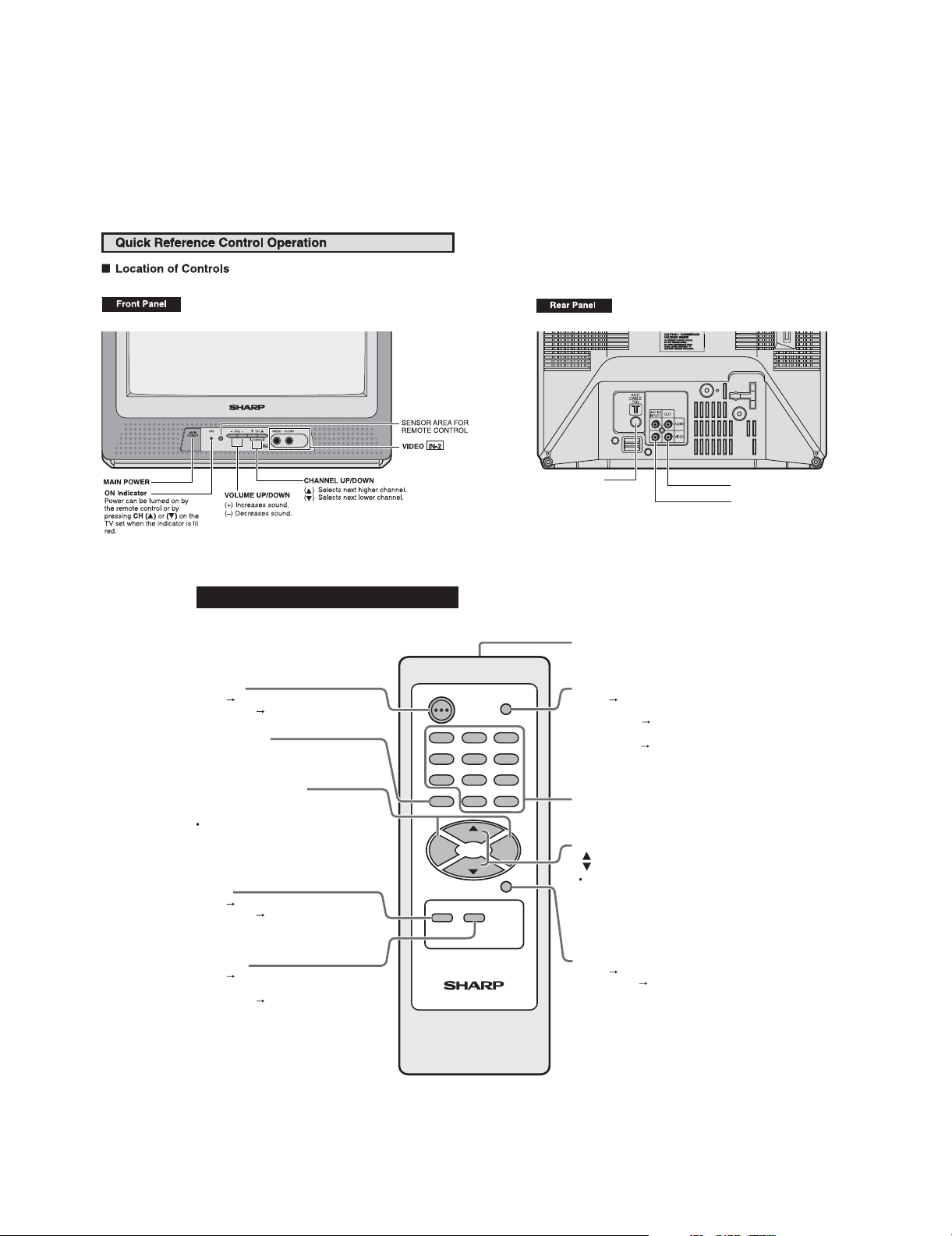
[1] LOCATION OF USER'S CONTROL
LOCATION OF USER'S CONTROL
Basic Remote Control Functions
POWER
On.
Press
Press again
FLASHBACK
Return to previous channel.
VOLUME UP/DOWN
(+) Increases sound.
(_) Decreases sound.
In menu mode, changes or selects
the TV adjustments.
MUTE
Press
Press again
Stand by..
Mutes sound.
Restores sound.
POWER
1
4
7
FLASHBACK
VOL
-
MUTE DISPLAY
CH
CH
2
5
8
0
MENU
INPUT
3
6
9
100
VOL
+
ANTENNA/CABLE
INPUT TERMINAL
Infrared Transmitter Window
INPUT
Press
Switch to external video
INPUT 1 mode..
Press 2 times Switch to external
video INPUT 2 mode.
Press 3 times Switch back to the
original TV mode.
REMOTE KEYPAD
Accesses any channel from keypad.
CHANNEL UP/DOWN
(
) Selects next higher channel.
(
) Selects next lower channel.
Moves the highlight bar of the
MENU screens.
AV OUT TERMINALS
AV-1IN/INPUT-1 TERMINALS
DISPLAY
Press Displays receiving channel
and Off Timer on the screen.
Press again Removes display.
2 – 1
TV
MENU
Press
Accesses MAIN MENU.
Press again
Exits MAIN MENU.
Page 4

TV14T1-LService Manual14T1-LMarketE
CHAPTER 3. INSTALLATION AND SERVICE INSTRUCTIONS
[1] INSTALLATION AND SERVICE INSTRUCTIONS
INSTALLATION AND SERVICE INSTRUCTIONS
Note: (1) When performing any adjustments to resistor controls and transformers use non-metallic
screwdrivers or TV alignment tools.
(2) Before performing adjustments, the TV set must be on at least 15 minutes.
14T1-L
CIRCUIT PROTECTION
The receiver is protected by a 3.15A fuse (F701),
mounted on PWB-A, wired into one side of the AC
line input.
X-RADIATION PROTECTOR CIRCUIT TEST
After service has been performed on the horizontal
deflection system, high voltage system, B+ system,
test the X-Radiation protection circuit to ascertain
proper operation as follows:
1. Apply 110~220V AC using a variac transformer for
accurate input voltage.
2. Allow for warm up and adjust all customer controls
for normal picture and sound.
3. Receive a good local channel.
4. Connect a digital voltmeter to C602 +ve Terminal
and make sure that the voltmeter reads 20 ±1.1V.
5. Apply external 27V DC at C602 +VE Terminal by
using an
6. To reset the protector, unplug the AC cord and
remove external 27V DC at C602 +VE Terminal.
Now make sure that normal picture appears on the
screen.
7. If the operation of the horizontal oscillator does not
stop in step 5, the circuit must be repaired before the
set is returned to the customer.
external DC supply, TV must shut off.
HIGH VOLTAGE CHECK
High voltage is not adjustable but must be checked
to verify that the receiver is operating within safe
and efficient design limitations as specified checks
should be as follows:
1. Connect an accurate high voltage meter between
ground and anode of picture tube.
2. Operate receiver for at least 15 minutes at 110~220V
AC line voltage, with a strong air signal or a properly
tuned in test signal.
3. Enter the service mode and set Y-mute ON by using
Service R/C.
4. The voltage should be approximately 24KV (at zero
beam).
If a correct reading cannot be obtained, check circuitry
for malfunctioning components. After the voltage test,
make Y-mute off to the normal m ode.
3 – 1
Page 5

14T1-L
conventional analog manner. The adjustments via the I2C bus control include preset-only items and
(c) Using the VOLUME UP/ DOWN key on the remote controller, the data can be modified.
TV14T1-LService Manual14T1-LMarketE
CHAPTER 5. ADJUSTMENT METHOD
[1] ADJUSTMENT METHOD
ADJUSTMENT PRECAUTIONS
This model's setting are adjusted in two different ways: through the I2C bus control and in the
variable data.
1. Setting the service mode by the microprocessor.
(a) Press and hold the local key "VOL DOWN" & "CH UP" and power on the main switch,
TV will enter into the SERVICE MODE. Or Key in service key of 40 (HEX) will enter the
service mode. The initial value of EEPROM are automatically preset when new EEPROM
is used. However, after the 1st time it will not be able to preset unless do the precedure
in section 2 as below.
(b) Press the CH DOWN / UP key on the remote controller to select the setting items
one by one.
(d) When press the local key "VOL DOWN" & "CH UP" at the same time or press service
key 40 (HEX), it will be released from the service mode.
2. Factory Presetting.
(1) Press remote controller key of code "B7" for 4 seconds, the initial values are
automatically preset.
(2) The initial data are preset as listed in page 2 until 7.
(3) Please modify the bus setup data.
Precaution
: If haven't done this initialization, malfunction might be happen.
3. For reference, please check with memory map RH-IXC227WJZZQ (See Attachment)
5 – 1
Page 6

There is three stage of Service Mode data
Setting Data (DEC)
Item
Setting Item
Setting Range
Default
IC
First stage data from V01 ~ V35
to go into second stage of service mode data, press MENU key
Second stage data from 008 ~ 1FF
Below is the contents of these data
Adjustment Mode Items
01 RF-AGC 0…63 UOC-TV 23 23
02 V-SLOPE 0…63 UOC-TV 31 31
03 S-COR 0…63 UOC-TV 16 16
04 DRI-RS 0…63 UOC-TV 32 32
05 DRI-GS 0…63 UOC-TV 32 32
06 DRI-BS 0…63 UOC-TV 32 32
07 CUT-RS 0…63 UOC-TV 16 16
08 CUT-GS 0…63 UOC-TV 16 16
09 CUT-BS 0…63 UOC-TV 16 16
10 SUB-BRI 0…63 UOC-TV 32 32
11 SUB-CON 0…63 UOC-TV 25
12 SUB-COL 0…63 UOC-TV 10 10
13 SUB-TINT 0…63 UOC-TV 36 36
14 SUB-SHARP 0…63 UOC-TV 32 32
15 DRI-RW 0…63 UOC-TV 38 38
16 DRI-GW 0…63 UOC-TV 32 32
17 DRI-BW 0…63 UOC-TV 19 19
18 DRI-RLW 0…63 UOC-TV 33 33
19 DRI-GLW 0…63 UOC-TV 32 32
20 DRI-BLW 0…63 UOC-TV 25 25
21 DRI-RC 0…63 UOC-TV 32 32
22 DRI-GC 0…63 UOC-TV 32 32
23 DRI-BC 0…63 UOC-TV 37 37
24 DRI-RLC 0…63 UOC-TV 32 32
25 DRI-GLC 0…63 UOC-TV 32 32
26 DRI-BLC 0…63 UOC-TV 34 34
27 V-SHI-60 0…63 UOC-TV 32 32
28 V-AMP-60 0…63 UOC-TV 32 32
29 H-SHI-60 0…63 UOC-TV 45 45
30 VSD 0/1 UOC-TV 0 0
31 CUT OFF 0…63 UOC-TV 27 27
32 DCXO 0…4 UOC-TV 2 1
33 ISP MODE 0/1 UOC-TV 0 0
34 BLOC 0…15 UOC-TV 6 6
35 SUB-VOL 0…60 UOC-TV 60 60
14T1-L
45 (BUS SETUP)
5 – 2
Page 7
14T1-L
ADJUSTMENT
ITEM
ADJUSTMENT
POSITION
CONTROL
PRE-ADJUST
REQUIREMENT
CONTENT
INPUT
CONDITION
OUTPUT
ADJUSTMENT
PROCEDURE
MAX - 0.1V dc
SYMBOL
RF INPUT
FIELD STRENGTH
56dBµV
(FIX)
TUNER AGC TERMINAL (JA352) OR CRT DISPLAY CONFIRMAT ION
(AT SELF ADJUSTMENT MODE)
1.GO TO SERVICE MODE
2.GO TO SERVICE DATA "RF-AGC" ITEM IN THE ADJUSTMENT, PRESS R/C TO OPERATE AUTOAGC KEY AND CONFIRM THE OK DISPLAY ON THE SCREEN .
3.BLUE DISPLAY WITH OK SIGN INDICATES T HE ADJUSTMENT IS WORKING PROPERLY.
(AT MANUAL ADJUSTMENT MODE)
[CHECKING CONFIRMATION ]
14T1-L
I2C CONTROL
BUS SET UP
US10CH HALF COLOR BAR
RF-AGC
01
STEP RANGE
0-63
HISTORY
OF REVISION
REVISED CONTENT .
MODEL NAME
1. SELECT "RF-AGC" ITEM IN THE ADJUSTMENT MODE. ADJUST THE "RF-AGC" BUS
DATA TO OBTAIN THE TUNER OUTPUT PIN DROP 0.1V~1.0V BELOW MAXIMUM
VOLTAGE.
2. CHANGE T HE ANTENNA INPUT SIGNAL TO 63~67 dBuV, AND MAKE SURE THERE IS NO
NOISE
3. CHANGE T HE ANTENNA INPUT SIGNAL TO 90~95 dBuV TO BE SURE THAT THERE IS NO
CROSS MODULATION BEAT.
5 – 3
Page 8

ADJUSTMENT
ITEM
ADJUSTMENT
POSITION
CONTROL
PRE-ADJUST
REQUIREMENT
CONTENT
INPUT
CONDITION
AC 220 V, RF INPUT, ZERO MAGNETIC FIELD
CRT DISPLAY CONFIRMATION
ADJUST THE V-SLOPE BUS DATA UNTILL THE OVERSCAN BECOME AS SPECIFIED BELOW.
CAUTION:- PLEASE AGING TV MORE THAN 10 MINUTES BEFORE ADJUSTMENT.
[CHECKING CONFIRMATION ]
14T1-L
I2CCONTROL
BUS SET UP,CRT PURITY
US 4 CH LION HEAD
V-SLOPE
02
STEP RANGE
0~63
HISTORY
OF REVISION
REVISED CONTENT .
MODEL NAME
A = Outofspec
B=OK
C = Out of spec
OUTPUT
14T1-L
ADJUSTMENT
PROCEDURE
SYMBOL
5 – 4
Page 9
14T1-L
ADJUSTMENT
ITEM
ADJUSTMENT
POSITION
CONTOROL
PRE-ADJUST
REQUIREMENT
INPUT
CONDITION
AC 220 V, RF INPUT, ZERO MAGNETIC FIELD
CRT DISPLAY CONFIRMATION
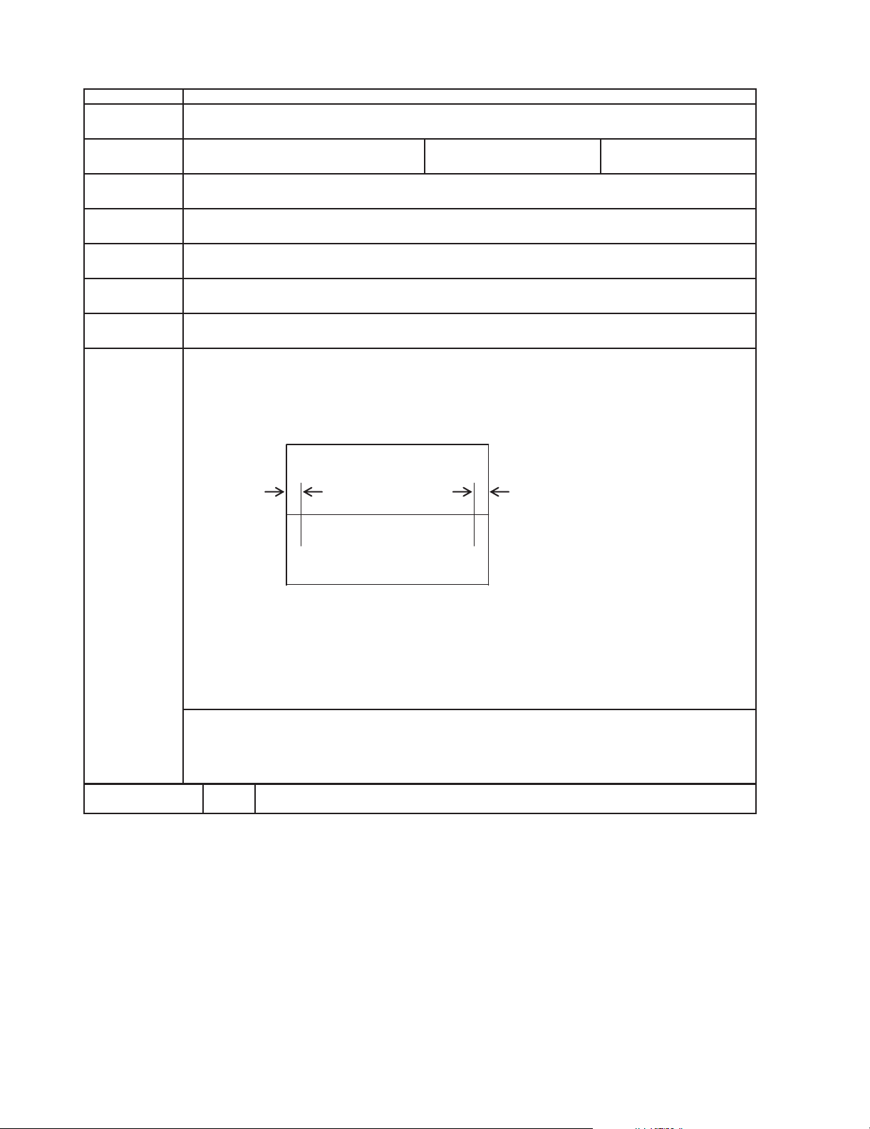
ADJUST V-SHIFT BUS DATA TO HAVE A MOST ACCEPTABLE VERTICAL POSITION.
THE MONOSCOPE PATTERN SHOULD BE BALANCE IN VERTICAL POSITION
[CHECKING CONFIRMATION ]
14T1-L
I2C CONTROL
BUS SET UP, CRT PURITY, V-SLOPE
US4CHLIONHEAD(MONOSCOPEPATTERN)
V-SHIFT-60
27
STEP RANGE
0-63
HISTORY
OFREVISION
REVISED CONTENT .
MODEL NAME
CONTENT
OUTPUT
ADJUSTMENT
PROCEDURE
SYMBOL
5 – 5
Page 10
ADJUSTMENT
ITEM
ADJUSTMENT
POSITION
CONTROL
PRE-ADJUST
REQUIREMENT
CONTENT
INPUT
CONDITION
ADJUST THE V-AMP-60 BUS DATA UNTILL THE OVERSCAN BECOME AS SPECIFIED BELOW .
[CHECKING CONFIRMATION ]
OVERSCAN 10 ± 2.5%
HISTORY
OF REVISION
REVISED CONTENT .
BUS SET UP,CRT PURITY, V-SLOPE, V-SHIFT 60
US 4 CH LION HEAD (MONOSCOPE PATTERN)
AC 220 V, RF INPUT, ZERO MAGNETIC FIELD
CRT DISPLAY CONFIRMATION
28
STEP RANGE
0~63
I2C CONTROL
MODEL NAME
14T1-L
V-AMP-60
OUTPUT
14T1-L
ADJUSTMENT
PROCEDURE
SYMBOL
5 – 6
Page 11
14T1-L
ADJUSTMENT
ITEM
ADJUSTMENT
POSITION
CONTROL
PRE-ADJUST
REQUIREMENT
INPUT
CONDITION
I2C BUS CONTROL
BUS SET UP,CRT-PURITY
MODEL NAME
H-SHIFT-60
STEP RANGE
29
0-63
14T1-L
AC 220 V, RF INPUT, ZERO MAGNETIC FIELD
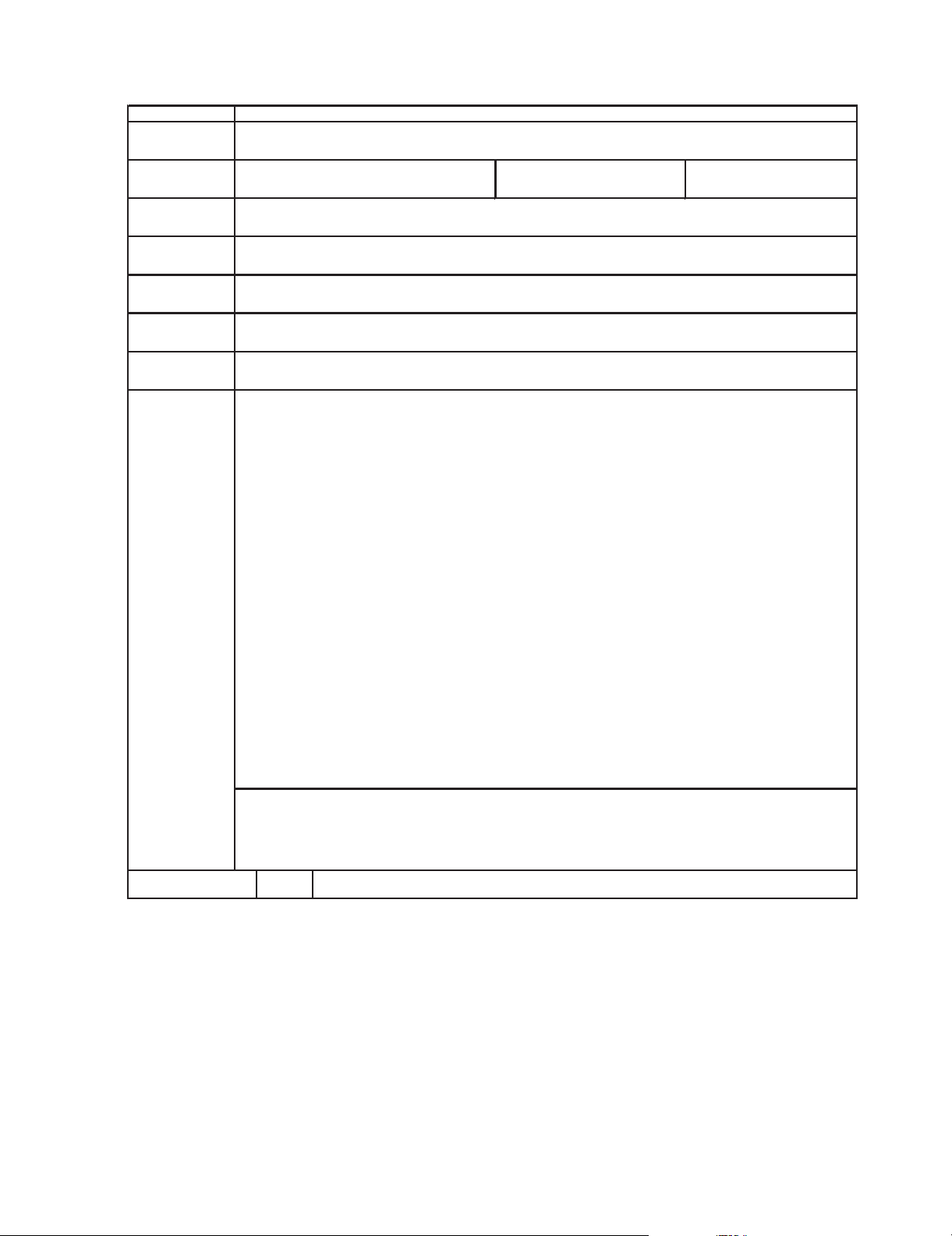
1.ADJUST THE
H-SHIFT
BUS DATA TO HAVE A BALANCE POSITION TO SPEC OF
A=B
[CHECKING CONFIRMATION ]
CONFIRMATION BY CRT SCREEN
HISTORY
OFREVISION
REVISED CONTENT .
US4CHLIONHEAD(MONOSCOPE)
B
A
CONTENT
OUTPUT
ADJUSTMENT
PROCEDURE
LEFT AND RIGHT SYMMETRICAL
SYMBOL
5 – 7
Page 12
ADJUSTMENT
ITEM
ADJUSTMENT
POSITION
CONTROL
PRE-ADJUST
REQUIREMENT
CONTENT
INPUT
CONDITION
MODEL NAME
CRT CUT OFF ADJUSTMENT
30 (VSD)
STEP RANGE
14T1-L
I2C CONTROL
BUS SET UP
AV MODE (WITHOUT SIGNAL) WITH BLUEBACK OFF
AC 220 V, AV INPUT
CONFIRMATION ON CRT DISPLAY.
[CHECKING CONFIRMATION ]
1) IN SERVICE MODE, SET CUT OFF TO 27, SUB-CON TO 45, SUB-BRI TO 32 AND DRI-RS, DRI-RS&
DRI-BS TO 32; CUT-RS, CUT-GS & CUT-BS TO 16 , SWITCH TV TO VIDEO MODE, BLUE BACK OFF,
WITHOUT SIGNAL.
2) GO TO ADJUSTMENT MODE ITEM VSD AND PRESS VOLUME UP AT R/C. ADJUST THE SCREEN
VR OF FBT SO THAT CUT-OFF LINE APPEAR IN LOW BRIGHT, THEN JUDGE THAT W HETHER THE
CUT-OFF LINE APPEAR IN RED OR GREEN OR BLUE COLOR. FIX THE CUT OFF DATA OF THE
COLOR APPEAR IN CUT-OFF LINE AND USE R/C TO ADJUST THE OTHER TWO AMONG CUT-RS,
CUT-GS & CUT-BS UNTIL COLOUR BECOME WHITE.
3)TURN THE SCREEN VR OF FBT SO THAT CUT-OFF LINE JUST DISAPPEAR.
HISTORY
OFREVISION
REVISED CONTENT .
OUTPUT
14T1-L
ADJUSTMENT
PROCEDURE
SYMBOL
5 – 8
Page 13
14T1-L
ADJUSTMENT
ITEM
ADJUSTMENT
POSITION
CONTROL
PRE-ADJUST
REQUIREMENT
INPUT
CONDITION
MODEL NAME
WHITE BALANCE
4,5,6,7,8,9
STEP RANGE
0~63
14T1-L
I2C BUS CONTROL
BUS SET UP,CRT PURITY, SCREEN
AV; W/B PATTERN 1 (PATTERN GENERATOR SX- 1006)
AC 220 V, AV INPUT
CONFIRMATION ON CRT DISPLAY.
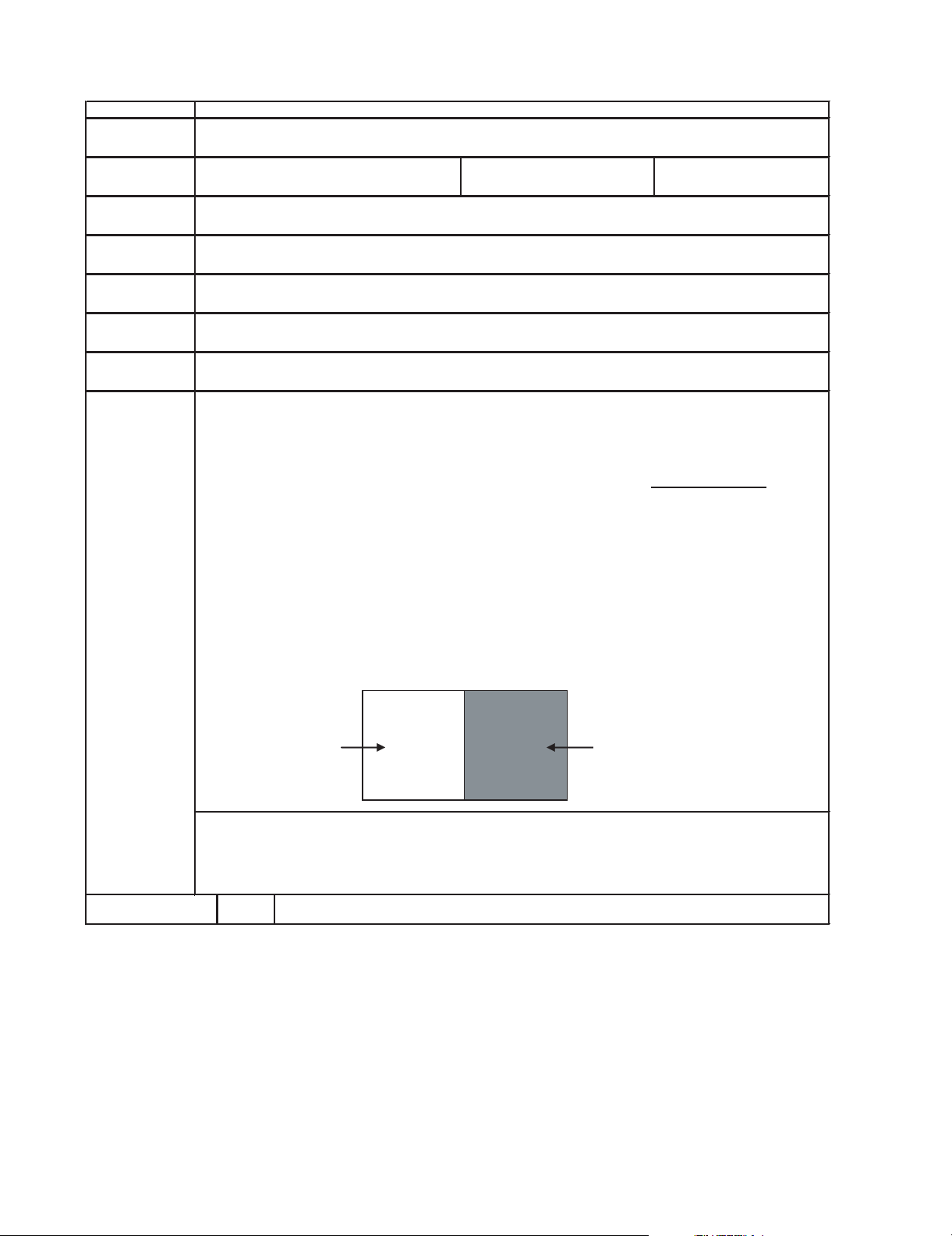
1)
WHITE
(HIGH BEAM)
FIRST LET THE GUN POINT AT
WHITE
POSITION (AS DRAWING ATTACH), ADJ
THE
PATTERN GENERATOR UPPER VR
UNTILYBECOME
150 cd/m
2
.
AFTER THAT, LET THE
GUN POINT AT WHITE POSITION AGAIN AND ADJUST THE BUS DATA OF DRI-RS AND
DRI-BS UNTLL THE AXIS OF COLOUR TEMPERATURE BECOME
X=0.273,Y=0.280
.
2)
DARK
(LOW BEAM)
LET THE GUN POINT AT DARK POSITION (AS DRAWING ATTACH),ADJUST THE
PATTERN GENERATOR LOWER VR UNTIL Y BECOME 5 cd/m2. ADJUST THE
TWO
SERVICE DATA
(AMONG CUT-RS, CUT-GS AND CUT-BS) WHICH HAVE CHOSEN AT CUT
OFF ADJUSTMENT SO THAT TO OBTAIN THE SIMILAR AXIS OF COLOUR TEMPERATURE
AS ABOVE.
*FOR ADJUSTMENT IN 1 & 2, MUST ALWAYS MAINTAIN THE Y AT 150cd/m2 (WHITE) AND
AT 5cd/m2 (DARK) WITH ADJUSTING THE UPPER AND LOWER VR OF PATTERN
GENERATOR.
**REPEAT STEP 1),2) TO GET A REGULATED LEVEL.
[CHECKING CONFIRMATION ]
X=0.273,Y=0.280 (11,600° K+1 MPCD)
HISTORY
OF REVISION
REVISED CONTENT .
WHITE
DARK
CONTENT
OUTPUT
ADJUSTMENT
PROCEDURE
SYMBOL
5 – 9
Page 14
ADJUSTMENT
ITEM
ADJUSTMENT
POSITION
CONTROL
PRE-ADJUST
REQUIREMENT
CONTENT
INPUT
CONDITION
REVISED CONTENT .
HISTORY
OF REVISION
[CHECKING CONFIRMATION ]
I2C CONTROL
BUS SET UP, CUT OFF, WHITE BALANCE
AV; WINDOW PATTERN (PATTERN GENERATOR SX- 1006)
AC 220 V, AV INPUT
MODEL NAME
BLOC
34
STEP RANGE
0~15
14T1-L
CONFIRMATION ON CRT DISPLAY.
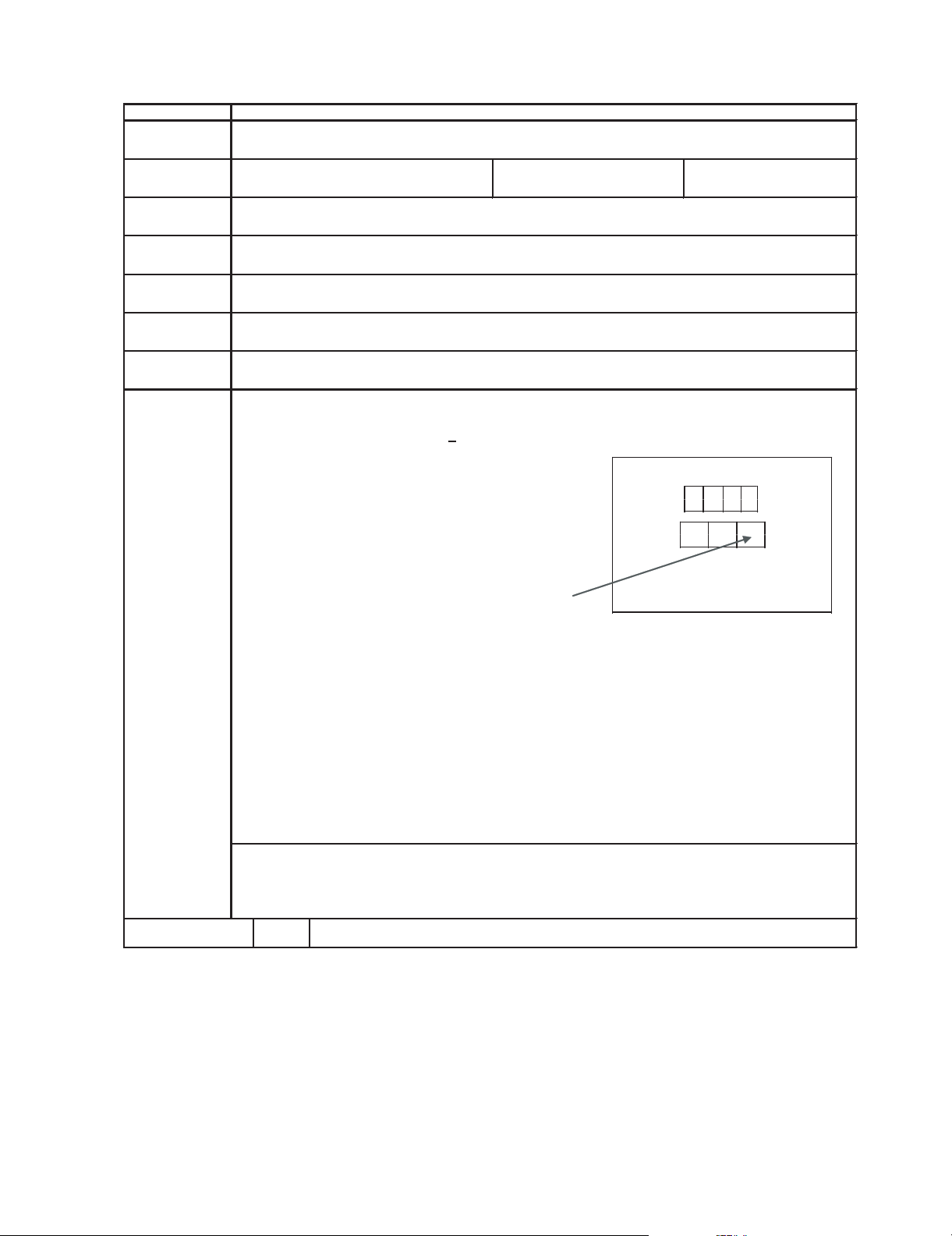
1)LET THE GUN POINT AT BLACK POSITION(AS ATTACH DRAWING), ADJUST
BLOC
BUS DATA
UNTIL LUMINANCE Y = 0.43cd/m
2
+ 0.1
BLACK
OUTPUT
14T1-L
ADJUSTMENT
PROCEDURE
SYMBOL
5 – 10
Page 15

14T1-L
ADJUSTMENT
ITEM
ADJUSTMENT
POSITION
CONTROL
PRE-ADJUST
REQUIREMENT
INPUT
CONDITION
MODEL NAME
SUB COLOUR
12
STEP RANGE
0~63
14T1-L
I2C BUS CONTROL
BUS SET UP, RF-AGC, CUT OFF, WHITE BALANCE
US 10 CH HALF COLOR BAR PATTERN
AC 220 V, RF INPUT
R-AMPTRBASE(JA801ORTP851)
CONFIRM WITH OSCILLOSCOPE
1)CONNECT THE OSCILLOSCOPE TO TP 851 RED TO OBTAIN WAVEFORM AS BELOW.
2)ADJUST THE 100% WHITE & RED PORTIONS OF COLOR BAR UNTIL THE SAME LEVEL
[CHECKING CONFIRMATION ]
HISTORY
OFREVISION
REVISED CONTENT .
W
Y
Cy
G
100% WHITE
MgRB
CONTENT
OUTPUT
ADJUSTMENT
PROCEDURE
SYMBOL
5 – 11
Page 16

ADJUSTMENT
ITEM
ADJUSTMENT
POSITION
CONTROL
PRE-ADJUST
REQUIREMENT
CONTENT
INPUT
CONDITION
MODEL NAME
SUB-TINT
13
STEP RANGE
0~63
14T1-L
I2C CONTROL
BUS SET UP, RF-AGC, CUT OFF, WHITE BALANCE, SUB-COLOUR
US 10 CH HALF COLOR BAR PATTERN
AC 220 V, RF INPUT
B-AMP TR BASE (JA810 OR TP853)
CONFIRRM WITH OSCILLOSCOPE
1)RECEIVE THE US 10 CH HALF COLOR BAR PATTERN.
2)CONNECT THE OSCILLOSCOPE TO TP 853 BLUE OUT.
[CHECKING CONFIRMATION ]
HISTORY
OFREVISION
REVISED CONTENT .
Range : 100mV/ Div USE PROBE 10:1
SWEEP TIME : 10 usec/Div
3) SELECT THE "SUB-TINT" ITEM IN THE ADJUSTMENT MODE. ADJUST THE "SUB-TINT" DATA
TO OBTAIN THE WAVEFORM AS SHOWN AS BELOW (W & MG SAME LEVEL)
G
G
Mg
R
B
Y
Cy
W
OUTPUT
14T1-L
ADJUSTMENT
PROCEDURE
SYMBOL
5 – 12
Page 17

14T1-L
ADJUSTMENT
ITEM
ADJUSTMENT
POSITION
CONTROL
PRE-ADJUST
REQUIREMENT
INPUT
CONDITION
MODEL NAME
X-RAY PROTECTION OPERATING CONFIRMATION
ˉ
STEP RANGE
ˉ
14T1-L
AC 220V, RF INPUT
CONFIRMATION BY THE CRT
[CHECKING CONFIRMATION ]
[VOLTAGE CONFIRMATION]
CHECK THE VOLTAGE OF C602 +VE TERMINAL AS SPECIFIED BELOW.
[OPERATION CONFIRMATION]
SUPPLY THE DC VOLTAGE (27V AS BELOW) TO C602 +VE TERMINAL AND MAKE SURE THE
PROTECTOR IS FUNCTIONED , HORIZONTAL OSCILATION STOP AND PICTURE DISAPPEAR.
[RECOVER INFORMATION]
PULL OUT THE AC CORD .
[CAUTION]
FROM THE RECOVER CONFIRMATION MENTIONED ABOVE,THE AC CODE MUST BE PULLED
OUT AT LEAST 5 SECONDS BEFORE PLUGGING IN AGAIN. (IN ORDER TO MAKE SURE THE CON HAS BEEN RESET.)
27V
HISTORY
OF REVISION
REVISED CONTENT .
TP VOLTAGE
20.6 ± 1.1V DC
PROTECTOR OPERATION VOLTAGE
ˉ
AFTER ALL ADJUSTMENT FINISHED.
US 4 CH LION HEAD (MONOSCOPE PATTERN)
CONTENT
OUTPUT
ADJUSTMENT
PROCEDURE
MODEL
14T1-L
SYMBOL
5 – 13
Page 18

ADJUSTMENT
ITEM
ADJUSTMENT
POSITION
CONTROL
PRE-ADJUST
REQUIREMENT
CONTENT
INPUT
CONDITION
MODEL
HISTORY
OF REVISION
REVISED CONTENT .
[CHECKING CONFIRMATION ]
CRT ANODE VOLTAGE
CONFIRM THE VOLTAGE OF CRT ANODE BY HIGH VOLTAGE METER AND MAKE SURE THE
READINGISASBELOW.
HIGH VOLTAGE
BELOW 25.5kV
ˉ
AFTER ALL ADJUSTMENT FINISHED.
US 4 CH LION HEAD (MONOSCOPE PATTERN)
AC 220V, RF INPUT
MODEL NAME
14T1-L
HIGH VOLTAGE
ˉ
STEP RANGE
ˉ
OUTPUT
14T1-L
ADJUSTMENT
PROCEDURE
14T1-L
SYMBOL
5 – 14
Page 19

14T1-L
(1) 1.79 Vp-p (H)
(2) 2.85 Vp-p (H)
(3) 2.42 Vp-p (H)
(4) 2.75 Vp-p (H)
(5) 2.60 Vp-p (H)
(6) 6.00 Vp-p (H)
(7) 1.06 Vp-p (V)
(8) 1.32 Vp-p (H)
(9) 39.30 Vp-p (H)
(10) 1190.0Vp-p (H)
(11) 52.10 Vp-p (V)
(12) 2.20 Vp-p (v)
(13) 121.40 Vp-p (H)
(14) 477.0Vp-p
(15) 4.90Vp-p (V)
(16) 83.60Vp-p (H)
(17) 57.80Vp-p (H)
(18) 82.2 Vp-p (H)
(19) 1.91 Vp-p (V)
TV14T1-LService Manual14T1-LMarketE
CHAPTER 6. WAVEFORMS
[1] WAVEFORMS
WAVEFORMS
6 – 1
Page 20

TV14T1-LService Manual14T1-LMarketE
CHAPTER 7. CHASSIS LAYOUT
[1] CHASSIS LAYOUT
*
)
14T1-L
(
'
&
%
$
7 – 1
Page 21

14T1-L
TV14T1-LService Manual14T1-LMarketE
CHAPTER 8. BLOCK DIAGRAM
[1] BLOCK DIAGRAM: MAIN UNIT
H
G
F
E
D
C
B
A
1
2
3
54
6
7
8
109
8 – 1
Page 22

14T1-L
1110
12
13
14
15
16
17
18
19
8 – 2
Page 23

TV14T1-LService Manual14T1-LMarketE
CHAPTER 9. DESCRIPTION OF SCHEMATIC DIAGRAM
[1] DESCRIPTION OF SCHEMATIC DIAGRAM
DESCRIPTION OF SCHEMATIC DIAGRAM
14T1-L
NOTES:
1. The unit of resistance "ohm" is omitted.
Ω
=1000Ω,M=MΩ)
(K=k
2. All resistors are 1/16 watt, unless otherwise noted.
3. All capacitors are
µµ
(P=pF=
4. (G) indicates
indicates line isolated ground.
5.
VOLTAGE MEASUREMENT CONDITIONS:
1. All DC voltages are measured with DVM connected
between points indicated and chassis ground, line
voltage set at 120V AC and all controls set for normal
picture unless otherwise indicated.
2. All voltages measured with 1000
signal.
F)
µ
F, unless otherwise noted.
±
2% tolerance may be used.
µ
V B & W or Color
WAVEFORM MEASUREMENT CONDITIONS:
1.
Photographs taken on a standard gated color bar
signal, the tint setting adjusted for proper color. The
wave shapes at the red, green and blue cathodes of
the picture tube depend on the tint, color level and
picture control.
2.
indicates waveform check points (See chart,
waveforms are measured from point indicated to
chassis ground.)
AND SHADED ( ) COMPONENTS
= SAFETY RELATED PARTS.
MARK= X-RAY RELATED PARTS.
DRGANNES MARQUES ET HACHRES ( ):
PIECES RELATIVES A LA SECURITE.
MARQUE : PIECS RELATIVE AUX RAYONS X.
This circuit diagram is a standard one, printed circuits
may be subject to change for product improvement
without prior notice.
9 – 1
Page 24

14T1-L
TV14T1-LService Manual14T1-LMarketE
CHAPTER 10. SCHEMATIC DIAGRAMS
[1] SCHEMATIC DIAGRAM: MAIN UNIT
+
*
)
(
'
&
%
$
10 – 1
Page 25

14T1-L
10 – 2
Page 26

14T1-L
[2] SCHEMATIC DIAGRAM: CRT UNIT
+
*
)
(
'
&
%
$
10 – 3
Page 27

14T1-L
[2] BLOCK DIAGRAM: CRT UNIT
+
*
)
(
'
&
%
$
8 – 3
Page 28

TV14T1-LService Manual14T1-LMarketE
CHAPTER 11. PRINTED WIRING BOARD ASSEMBLIES
[1] PWB-A: MAIN UNIT (Wiring Side)
+
*
14T1-L
)
(
'
&
%
$
11 – 1
Page 29

14T1-L
[2] PWB-A: MAIN UNIT (Chip Parts Side)
+
*
)
(
'
&
%
$
11 – 2
Page 30

[3] PWB-B: CRT UNIT (Wiring Side)
+
*
14T1-L
)
(
'
&
%
$
11 – 3
Page 31

14T1-L
[4] PWB-B: CRT UNIT (Chip Parts Side)
+
*
)
(
'
&
%
$
11 – 4
Page 32

PartsGuide
PARTS GUIDE
No. XXXXXXXXXXXX
S878314T1L
XXXXXXXX
14T1-L
[1] PICTURE TUBE
[2] PRINTED WIRING BOARD
ASSEMBLIES
[3] MAIN UNIT
[4] CRT UNIT
MODEL
CONTENTS
14T1-L
[5] SUPPLIED ACCESSORIES
[6] CABINET PARTS
[7] PACKING PARTS
INDEX
Parts marked with " " are important for maintaining the safety of the set. Be sure to replace these
parts with specified ones for maintaining the safety and performance of the set.
This document has been published to be used
for after sales service only.
The contents are subject to change without notice.
Page 33

14T1-L
NO. PARTS CODE
[1] PICTURE TUBE
!
!
VB370BVBK1S9E R SEMI-ITC Picture Tube
RCILGA114WJZZ R Degaussing Coil
QEARC1422PEZZ R Ground-Part
PMAGF3045CEZZ R Magnet
[2] PRINTED WIRING BOARD ASSEMBLIES
DUNTKE161WEA1 - - MAIN Unit
DUNTKE162WEA1 - - CRT Unit
[3] MAIN UNIT
TU201 RTUNQA037WJZZ R Tuner
!
!
!
!
IC301 VHILA42031E-1 R LA4203E-1
IC501 VHISTV9302B-1 R STV9302B
IC701 VHISTRW5453-1 AM R I.C.
IC801 RH-IXC227WJZZQ R I.C.
IC1003 VHIBR24L08F-1Y AE R BR24L08F-WE2
Q201 VS2SC2735//1EY R 2SC2735//1E
Q302 VS2SA1530AR-1Y AB R 2SA1530AR
Q601 VS2SC2235Y/1E+ AE R 2SC2235
Q602 VSTT2140+++-F AG R TT2140
Q603 VS2SC3198-G-1+ AA R 2SC3198
Q751 VS2SD468-C/-1+ AD R 2SD468
Q754 VS2SC3198-G/-1+ AD R 2SC3198
Q755 VS2SC3198-G/-1+ AD R 2SC3198
Q801 VS2SC3928AR-1Y AB R 2SC3928AR
Q803 VS2SC3928AR-1Y AB R 2SC3928AR
Q1070 VS2SC3928AR-1Y AB R 2SC3928AR
D201 VHEZJ33C+++1EY AA R Zener Diode , 33V
D203 VHDHSS4148+-1Y AA R Diode
D204 VHDHSS4148+-1Y AA R Diode
D301 VHEZJ12B+++1EY AA R Diode
D302 VHDHSS4148+-1Y AA R Diode
D303 VHDHSS4148+-1Y AA R Diode
D393 RH-DX0302CEZZ AE R Diode , DX0302CE
D503 RH-EX0612GEZZY AB R Zener Diode , 5.1V
D505 RH-DX0441CEZZY AC R Diode , DX0441CE
D510 RH-DX0131CEZZY AC R Diode , DX0131CE
D511 RH-DX0131CEZZY AC R Diode , DX0131CE
D602 VHD1SS244//-1Y AB R Diode , 1SS244
D603 VHEZJ27B+++1EY AA R Zener Diode , 27V
D605 VHDHSS4148+-1Y AA R Diode
D606 RH-DX0131CEZZY AC R Diode , DX0131CE
D607 VHDHSS4148+-1Y AA R Diode
D608 VHEZJ5R6B++1EY AA R Zener Diode , 5.6V
D701 RH-DX0476CEZZ AG R Diode , DX0476CE
D706 RH-DX0066GEZZY AC R Diode , DX0066GE
D707 RH-DX0066GEZZY AC R Diode , DX0066GE
D709 RH-DX0066GEZZY AC R Diode , DX0066GE
D710 VHDHSS4148+-1Y AA R Diode
D715 VHEZJ5R6B++1EY AA R Zener Diode , 5.6V
D720 RH-DX0131CEZZY AC R Diode , DX0131CE
D721 RH-DX0066GEZZY AC R Diode , DX0066GE
D722 VHEZJ27D+++1EY AA R Zener Diode , 27V
D723 VHEZJ12B+++1EY AA R Zener Diode , 12.03V
D724 VHEZJ4R3B++1EY R Zener Diode , 4.3V
D725 VHDHSS4148+-1Y AA R Diode
D732 VHEZJ8R2A++1EY AB R Zener Diode , 8.2V
D736 VHEZJ36C+++1EY AB R Zener Diode , 36V
D751 RH-DXA044WJZZ R Diode , DXA044WJ
D752 RH-DX0247CEZZ AE R Diode , DX0247CE
D754 VHEZJ5R1A++1EY R Zener Diode , 5.1V
D758 VHEZJ3R3A++1EY R Zener Diode , 3.3V
D759 VHDHSS4148+-1Y AA R Diode
D760 VHEZJ8R2B++1EY AB R Zener Diode , 8.2V
D764 VHDHSS4148+-1Y AA R Diode
D801 RH-EX0277TAZZY AA R Zener Diode
D802 RH-EX0277TAZZY AA R Zener Diode
D803 RH-EX0277TAZZY AA R Zener Diode
D804 VHDHSS4148+-1Y AA R Diode
D805 VHDHSS4148+-1Y AA R Diode
D806 RH-EX1393CEZZY AB R Zener Diode , 5.1V
D807 VHEZJ5R1B++1EY AC R Zener Diode , 5.1V
D808 VHEZJ12B+++1EY AC R Zener Diode , 12V
D1001 RH-PX0013PEZZ AC R Photodiode
D1003 RH-EX1393CEZZY AB R Zener Diode , 5.1V
D1004 RH-EX1393CEZZY AB R Zener Diode , 5.1V
D1005 VHDHSS4148+-1Y AA R Diode
D1007 VHDHSS4148+-1Y AA R Diode
D1008 VHDHSS4148+-1Y AA R Diode
VA701 RH-VXA182WJZZ R Varistor
X801 RCRSAA058WJZZ R Crystal
L203 VP-DF270K0000Y AB R Peaking 27mH
L204 VP-XF1R2K0000Y AB R Peaking 1.2mH
L205 VP-XF2R7K0000Y AB R Peaking 2.7mH
PRICE
RANK
NEW
MARK
PAR T
DELIVERY
DESCRIPTION
2
Page 34

NO. PARTS CODE
PRICE
RANK
NEW
MARK
PAR T
DELIVERY
[3] MAIN UNIT
L701 RCILFA187WJZZ AD R Coil
L802 VP-XF4R7K0000Y AB R Peaking 4.7mH
L804 VP-DF100K0000Y AB R Peaking 10mH
L805 VP-DF100K0000Y AB R Peaking 10mH
L807 VP-DF100K0000Y AB R Peaking 10mH
L808 VP-XF100K0000Y AB R Peaking 10mH
L809 VP-XF100K0000Y AB R Peaking 10mH
L810 VP-XF100K0000Y AB R Peaking 10mH
L812 VP-XF4R7K0000Y AB R Peaking 4.7mH
L813 VP-XF4R7K0000Y AB R Peaking 4.7mH
SF201 RFILCA055WJQZS R Coil
T602 RTRNFA140WJZZ R H-Volt Transformer
T603 RTRNZA058WJZZ AD R Transformer
T702 RTRNWA287WJZZ R Transformer
C202 VCEA0A1AW108M+ AC R 1000 10V Electrolytic
C203 VCKYCY1HF103ZY AA R 0.01 50V Ceramic
C206 VCEA0A1HW106M+ AB R 10 50V Electrolytic
C207 VCKYCY1HB103ZY AA R 0.01 50V Ceramic
C208 VCKYCY1HB103ZY AA R 0.01 50V Ceramic
C209 VCKYCY1HB103ZY AA R 0.01 50V Ceramic
C210 VCKYCY1HB103ZY AA R 0.01 50V Ceramic
C211 VCEA0A1HW475M+ AB R 4.7 50V Electrolytic
C301 VCEA0A1EW476M+ AB R 47 25V Electrolytic
C304 VCEA0A1HW105M+ AB R 1 50V Electrolytic
C305 VCKYCY1HB153KY AA R 0.15 50V Ceramic
C306 VCEA0A1CW336M+ AB R 33 16V Electrolytic
C307 VCEA0A1AW108M+ AC R 1000 10V Electrolytic
C308 VCEA0A1EW477M+ AD R 470 25V Electrolytic
C309 VCFYFA1HA474J+ AE R 0.47 50V Mylar
C314 VCEA0A1HW475M+ AB R 4.7 50V Electrolytic
C370 VCEA0A1CW106M+ AB R 10 16V Electrolytic
C372 VCE9GA1HW225M+ AB R 2.2 50V Electrolytic
C383 VCEA0A1CW106M+ AB R 10 16V Electrolytic
C391 VCKYPA1HB102K+ AA R 1000p 50V Ceramic
C393 VCEA0A1EW108M+ AD R 1000 25V Electrolytic
C395 VCE9GA1HW225M+ AB R 2.2 50V Electrolytic
C451 VCEA0A1CW477M+ AC R 470 16V Electrolytic
C505 VCEA0A1HW107M+ AB R 100 50V Electrolytic
C508 VCFYAA2AA224J+ AD R 0.22 100V Mylar
C511 VCEA0A1VW477M+ AB R 470 35V Electrolytic
C512 VCKYPA2HB102K+ AA R 1000p 500V Ceramic
C515 VCKYPA2HB102K+ AA R 1000p 500V Ceramic
C516 VCEA0A1CW477M+ AC R 470 16V Electrolytic
C601 VCQYTA1HM563J+ AB R 0.56 50V Mylar
C602 VCEA0A1HW475M+ AB R 4.7 50V Electrolytic
C604 VCEA0A2EW336M+ AD R 33 250V Electrolytic
C606 VCKYPA2HB102K+ AA R 1000p 500V Ceramic
C607 VCFPVC3ZA612H AD R 6.1 1.8KV Metalized Polypro Film
C608 VCQYTA1HM472J+ AB R 4.7 50V Mylar
C611 VCFPVC2EB334J AD R 0.33 200V Metalized Polypro Film
C650 VCKYPA2HB101K+ AB R 100p 500V Ceramic
C701 RC-FZ032SCEZZ AD R 220 275V Metalized Plastic Film
C702 RC-KZ0029CEZZ+ AC R 0.01 250V Ceramic
C703 RC-KZ0029CEZZ+ AC R 0.01 250V Ceramic
C704 RC-KZ0029CEZZ+ AC R 0.01 250V Ceramic
C705 RC-EZA095WJZZ AM R 220 400V Electrolytic
C706 VCFYFA1HA105J+ AE R 1 50V Mylar
C708 VCKYPA1HB221K+ AB R 220p 50V Ceramic
C709 VCQYTA1HM103J+ AB R 0.01 50V Mylar
C710 VCQYTA1HM222J+ AB R 2.2 50V Mylar
C711 VCKYPA1HB222K+ AB R 2200p 50V Ceramic
C713 RC-KZ0102GEZZ AC R 2kV Ceramic
C719 VCEA0A1HW476M+ AB R 47 50V Electrolytic
C720 VCKYPA2HB102K+ AA R 1000p 500V Ceramic
C721 VCEA0A1CW477M+ AC R 470 16V Electrolytic
C722 VCEA0A1CW476M+ AC R 47 16V Electrolytic
C750 VCKYPA2HB102K+ AA R 1000p 500V Ceramic
C752 VCKYPH3DB561K AC R 560p 2KV Ceramic
C753 RC-EZA235WJZZ AD R 100 160V Electrolytic
C754 RC-EZA522WJZZ AD R 33 160V Electrolytic
C756 VCEA0A1EW228M+ AE R 2200 25V Electrolytic
C758 VCEA0A1AW107M+ AB R 100 10V Electrolytic
C759 VCKYCY1HB104KY AA R 0.1 50V Ceramic
C784 VCKYPH3DB561K AC R 560p 2KV Ceramic
C808 VCEA0A1HW475M+ AB R 4.7 50V Electrolytic
C809 VCKYCY1HB104KY AA R 0.1 50V Ceramic
C810 VCEA0A1CW106M+ AB R 10 16V Electrolytic
C812 VCKYCY1HB104KY AA R 0.1 50V Ceramic
C815 VCKYCY1HB104KY AA R 0.1 50V Ceramic
C816 VCEA0A1CW476M+ AB R 47 16V Electrolytic
C817 VCKYCY1HB103KY AA R 0.01 50V Ceramic
C818 VCEA0A1CW476M+ AB R 47 16V Electrolytic
C820 VCKYCY1AB105KY AA R 1 10V Ceramic
C822 VCKYCY1AB105KY AA R 1 10V Ceramic
C825 VCEA0A1HW475M+ AB R 4.7 50V Electrolytic
14T1-L
DESCRIPTION
3
Page 35

14T1-L
NO. PARTS CODE
[3] MAIN UNIT
C826 VCKYCY1HB104KY AA R 0.1 50V Ceramic
C827 VCEA0A1CW106M+ AB R 10 16V Electrolytic
C828 VCKYCY1HB104KY AA R 0.1 50V Ceramic
C829 VCEA0A1CW106M+ AB R 10 16V Electrolytic
C830 VCKYCY1HB104KY AA R 0.1 50V Ceramic
C831 VCEA0A1CW106M+ AB R 10 16V Electrolytic
C832 VCKYCY1HB103KY AA R 0.01 50V Ceramic
C833 VCEA0A1CW106M+ AB R 10 16V Electrolytic
C835 VCFYFA1HA154J+ AA R 0.15 50V Mylar
C836 VCKYCY1HB102KY AA R 1000p 50V Ceramic
C837 VCKYCY1HB102KY AA R 1000p 50V Ceramic
C839 VCKYCY1HB223KY AA R 0.22 50V Ceramic
C840 VCFYFA1HA224J+ AA R 0.22 50V Mylar
C841 VCQYTA1HM682J+ AB R 6.8 50V Mylar
C842 VCKYCY1AB105KY AA R 1 10V Ceramic
C843 VCEA0A1HW475M+ AB R 4.7 50V Electrolytic
C844 VCFYFA1HA103J+ AA R 0.01 50V Mylar
C845 VCKYCY1CF224ZY AB R 0.22 16V Ceramic
C846 VCEA0A1AW107M+ AB R 100 10V Electrolytic
C847 VCEA0A1CW106M+ AB R 10 16V Electrolytic
C848 VCKYCY1HB104KY AA R 0.1 50V Ceramic
C1001 VCEA0A1AW107M+ AB R 100 10V Electrolytic
C1003 VCEA0A1CW106M+ AB R 10 16V Electrolytic
C1004 VCKYCY1CF474ZY AB R 0.47 16V Ceramic
C1005 VCCCCY1HH101JY AA R 100p 50V Ceramic
C1016 VCKYCY1EF104ZY AA R 0.1 25V Ceramic
C1081 VCFYFA1HM104J+ AA R 0.1 50V Mylar
C1852 VCKYCY1HF224ZY AA R 0.22 50V Ceramic
C1853 VCEA0A1HW104M+ AB R 0.1 50V Electrolytic
C1859 VCEA0A1HW106M+ AB R 10 50V Electrolytic
RJ14 VRS-CY1JF000JY AA R 0 1/16W Metal Oxide
RJ17 VRS-CY1JF000JY AA R 0 1/16W Metal Oxide
RJ22 VRS-CY1JF000JY AA R 0 1/16W Metal Oxide
RJ23 VRS-CY1JF000JY AA R 0 1/16W Metal Oxide
R201 VRD-RA2BE101JY AA R 100 1/8W Carbon
R202 VRD-RA2BE101JY AA R 100 1/8W Carbon
R205 VRS-CY1JF680JY AA R 68 1/16W Metal Oxide
R206 VRS-CY1JF272JY AA R 2.7K 1/16W Metal Oxide
R207 VRS-CY1JF221JY AA R 220 1/16W Metal Oxide
R208 VRS-CY1JF221JY AA R 220 1/16W Metal Oxide
R209 VRS-CY1JF392JY AA R 3.9K 1/16W Metal Oxide
R213 VRS-CY1JF103JY AA R 10K 1/16W Metal Oxide
R214 VRS-CY1JF563JY AA R 56K 1/16W Metal Oxide
R216 VRS-RG3LB393J+ AC R 39K 3W Metal Film
R220 VRS-CY1JF221JY AA R 220 1/16W Metal Oxide
R301 VRD-RA2BE822JY AA R 8.2 1/8W Carbon
R303 VRS-CY1JF473JY AA R 47K 1/16W Metal Oxide
R304 VRD-RA2BE223JY AA R 22K 1/8W Carbon
R305 VRS-CY1JF274JY AA R 270K 1/16W Metal Oxide
R314 VRS-CY1JF561JY AA R 560 1/16W Metal Oxide
R315 VRS-CY1JF122JY AA R 1.2K 1/16W Metal Oxide
R322 VRS-CY1JF104JY AA R 100K 1/16W Metal Oxide
R323 VRD-RA2BE101JY AA R 100 1/8W Carbon
R324 VRS-CY1JF102JY AA R 1K 1/16W Metal Oxide
R325 VRD-RM2HD1R0JY AA R 1 1/2W Carbon
R365 VRS-CY1JF103JY AA R 10K 1/16W Metal Oxide
R366 VRS-CY1JF682JY AA R 6.8K 1/16W Metal Oxide
R372 VRS-CY1JF103JY AA R 10K 1/16W Metal Oxide
R383 VRS-CY1JF103JY AA R 10K 1/16W Metal Oxide
R384 VRS-CY1JF682JY AA R 6.8K 1/16W Metal Oxide
R391 VRN-RL3ABR10J+ AA R 10 1W Metal Film
R431 VRD-RA2BE151JY AA R 150 1/8W Carbon
R432 VRS-CY1JF221JY AA R 220 1/16W Metal Oxide
R458 VRS-CY1JF103JY AA R 10K 1/16W Metal Oxide
R459 VRD-RA2EE750JY AA R 75 1/4W Carbon
R461 VRS-CY1JF750JY AA R 75 1/16W Metal Oxide
R462 VRS-CY1JF151JY AA R 150 1/16W Metal Oxide
R503 VRN-RL3DB2R7J+ AB R 2.7 2W Metal Film
R506 VRS-RG3AB331J+ AB R 330 1W Metal Oxide
R507 VRD-RM2HD1R0JY AA R 1 1/2W Carbon
R508 QJUM-0001AJFWY R Jumper wire
R509 QJUM-0001AJFWY R Jumper wire
R513 VRS-CY1JF222JY AA R 2.2K 1/16W Metal Oxide
R515 VRS-CY1JF183JY AA R 18K 1/16W Metal Oxide
R520 VRS-CY1JF272JY AA R 2.7K 1/16W Metal Oxide
R601 VRS-VV3AB121J AA R 120 2W Metal Oxide
R602 VRD-RA2BE393JY AA R 39K 1/8W Carbon
R603 VRD-RA2BE273JY AA R 27K 1/8W Carbon
R604 VRD-RA2BE563JY AA R 56K 1/8W Carbon
R605 VRD-RM2HD154JY AA R 150K 1/2W Carbon
R606 VRN-RL3LBR18J+ AD R 18 3W Metal Film
R607 VRS-VV3AB101J AA R 100 2W Metal Oxide
R608 VRN-RL3LBR22J+ AD R 22 3W Metal Film
R609 VRD-RM2HD270JY AA R 27 1/2W Carbon
R611 VRN-RL3AB1R2J+ AB R 1.2 1W Metal Film
PRICE
RANK
NEW
MARK
PAR T
DELIVERY
DESCRIPTION
4
Page 36

NO. PARTS CODE
PRICE
RANK
NEW
MARK
PAR T
DELIVERY
[3] MAIN UNIT
R612 VRD-RM2HD270JY AA R 27 1/2W Carbon
R614 VRS-CY1JF154JY AA R 150K 1/16W Metal Oxide
R615 VRS-CY1JF102JY AA R 1K 1/16W Metal Oxide
R616 VRS-CY1JF102JY AA R 1K 1/16W Metal Oxide
R617 VRS-CY1JF123JY AA R 12K 1/16W Metal Oxide
R618 VRS-CY1JF222JY AA R 2.2K 1/16W Metal Oxide
R621 VRN-RG2HC150J+ AB R 15 1/2W Metal Oxide
R622 VRS-RG3DB682J+ AB R 6.8K 2W Metal Film
R625 VRD-RM2HD184JY AA R 180K 1/2W Carbon
R626 VRS-CY1JF472JY AA R 4.7K 1/16W Metal Oxide
R627 VRD-RA2BE222JY AA R 2.2K 1/8W Carbon
R631 VRS-RG3LB391J+ AC R 390 3W Metal Film
R637 VRD-RA2BE103JY AA R 10K 1/8W Carbon
R638 VRS-CY1JF101JY AA R 100 1/16W Metal Oxide
R639 VRD-RM2HD471JY AA R 470 1/2W Carbon
R702 VRS-RG3AB124J+ AB R 120K 2W Metal Oxide
R704 VRD-RA2BE221JY AA R 220 1/8W Carbon
R705 VRN-RL3DBR82J+ AA R 82 2W Metal Film
R706 VRN-RL3DBR22J+ AB R 22 2W Metal Film
R710 VRD-RM2HD5R6JY AA R 5.6 1/2W Carbon
R720 VRD-RA2EE472JY AA R 4.7K 1/4W Carbon
R721 VRD-RA2BE683JY AA R 68K 1/8W Carbon
R726 VRN-RL2HCR47J+ AB R 47 1/2W Metal Oxide
R727 VRD-RA2EE102JY AA R 1K 1/4W Carbon
R733 VRD-RA2BE273JY AA R 27K 1/8W Carbon
R751 VRD-RA2BE273JY AA R 27K 1/8W Carbon
R752 RR-DZ0049CEZZY R 39M 1/2W Carbon Film
R753 VRD-RM2HD124JY AA R 12K 1/2W Carbon
R754 VRS-RG3AB151J+ AB R 150 2W Metal Oxide
R755 VRN-RL3AB3R9J+ AB R 3.9 1W Metal Film
R758 VRD-RA2BE471JY AA R 470 1/8W Carbon
R761 VRD-RA2EE821JY AA R 820 1/4W Carbon
R763 VRN-RL3AB8R2J+ AB R 8.2 1W Metal Film
R764 VRD-RM2HD100JY AA R 10 1/2W Carbon
R765 VRD-RM2HD100JY AA R 10 1/2W Carbon
R766 VRD-RM2HD100JY AA R 10 1/2W Carbon
R803 VRD-RA2BE101JY AA R 100 1/8W Carbon
R804 VRD-RA2BE101JY AA R 100 1/8W Carbon
R805 VRD-RA2BE101JY AA R 100 1/8W Carbon
R806 VRD-RA2BE101JY AA R 100 1/8W Carbon
R807 VRS-CY1JF222JY AA R 2.2K 1/16W Metal Oxide
R808 VRD-RA2BE471JY AA R 470 1/8W Carbon
R810 VRS-CY1JF100JY AA R 10 1/16W Metal Oxide
R811 VRD-RA2BE391JY AA R 390 1/8W Carbon
R812 VRD-RA2BE223JY AA R 22K 1/8W Carbon
R813 VRD-RA2BE470JY AA R 47 1/8W Carbon
R814 VRS-CY1JF391JY AA R 390 1/16W Metal Oxide
R815 VRS-CY1JF103JY AA R 15K 1/16W Metal Oxide
R816 VRD-RA2BE101JY AA R 100 1/8W Carbon
R817 VRD-RA2BE101JY AA R 100 1/8W Carbon
R818 VRD-RA2BE101JY AA R 100 1/8W Carbon
R819 VRS-CY1JF101JY AA R 100 1/16W Metal Oxide
R820 VRD-RA2BE470JY AA R 47 1/8W Carbon
R821 VRS-CY1JF102JY AA R 1K 1/16W Metal Oxide
R822 VRS-CY1JF101JY AA R 100 1/16W Metal Oxide
R824 VRS-CY1JF103JY AA R 15K 1/16W Metal Oxide
R825 VRS-CY1JF333JY AA R 33K 1/16W Metal Oxide
R827 VRD-RM2HD151JY AA R 150 1/2W Carbon
R828 VRS-CY1JF391JY AA R 390 1/16W Metal Oxide
R829 VRD-RA2BE393GY AA R 39K 1/8W Carbon
R830 VRD-RA2BE101JY AA R 100 1/8W Carbon
R831 VRD-RA2BE101JY AA R 100 1/8W Carbon
R833 VRS-CY1JF123JY AA R 12K 1/16W Metal Oxide
R834 VRS-CY1JF101JY AA R 100 1/16W Metal Oxide
R837 VRD-RA2BE332JY AA R 3.3K 1/8W Carbon
R839 VRS-CY1JF104JY AA R 100K 1/16W Metal Oxide
R845 VRD-RA2BE103JY AA R 10K 1/8W Carbon
R848 VRD-RA2BE181JY AA R 180 1/8W Carbon
R862 VRD-RA2BE101JY AA R 100 1/8W Carbon
R1004 VRD-RA2BE101JY AA R 100 1/8W Carbon
R1005 VRD-RA2BE101JY AA R 100 1/8W Carbon
R1006 VRS-CY1JF332JY AA R 3.3K 1/16W Metal Oxide
R1007 VRD-RA2BE101JY AA R 100 1/8W Carbon
R1008 VRD-RA2BE101JY AA R 100 1/8W Carbon
R1010 VRD-RA2BE101JY AA R 100 1/8W Carbon
R1011 VRD-RA2BE101JY AA R 100 1/8W Carbon
R1012 VRD-RA2BE101JY AA R 100 1/8W Carbon
R1013 VRD-RA2BE101JY AA R 100 1/8W Carbon
R1014 VRD-RA2BE101JY AA R 100 1/8W Carbon
R1015 VRS-CY1JF332JY AA R 3.3K 1/16W Metal Oxide
R1016 VRS-CY1JF332JY AA R 3.3K 1/16W Metal Oxide
R1017 VRS-CY1JF101JY AA R 100 1/16W Metal Oxide
R1019 VRD-RA2BE101JY AA R 100 1/8W Carbon
R1020 VRS-CY1JF152JY AA R 1.5K 1/16W Metal Oxide
R1021 VRS-CY1JF561JY AA R 560 1/16W Metal Oxide
14T1-L
DESCRIPTION
5
Page 37

14T1-L
NO. PARTS CODE
PRICE
RANK
NEW
MARK
[3] MAIN UNIT
R1022 VRS-CY1JF181JY AA R 180 1/16W Metal Oxide
R1023 VRS-CY1JF222JY AA R 2.2K 1/16W Metal Oxide
R1024 VRS-CY1JF101JY AA R 100 1/16W Metal Oxide
R1025 VRS-CY1JF152JY AA R 1.5K 1/16W Metal Oxide
R1026 VRS-CY1JF681JY AA R 680 1/16W Metal Oxide
R1027 VRS-CY1JF104JY AA R 100K 1/16W Metal Oxide
R1028 VRD-RA2BE181JY AA R 180 1/8W Carbon
R1029 VRD-RA2BE103JY AA R 10K 1/8W Carbon
R1031 VRS-CY1JF101JY AA R 100 1/16W Metal Oxide
R1032 VRD-RA2BE680JY AA R 68 1/8W Carbon
R1035 VRD-RA2BE103JY AA R 10K 1/8W Carbon
R1036 VRS-CY1JF122JY AA R 1.2K 1/16W Metal Oxide
R1037 VRS-CY1JF103JY AA R 10K 1/16W Metal Oxide
R1038 VRS-CY1JF101JY AA R 100 1/16W Metal Oxide
R1039 VRS-CY1JF101JY AA R 100 1/16W Metal Oxide
R1078 VRS-CY1JF332JY AA R 3.3K 1/16W Metal Oxide
R1079 VRS-CY1JF332JY AA R 3.3K 1/16W Metal Oxide
S701 QSW-P0612CEZZ AG R Switch , POWER
S1001 QSW-KA019WJZZ+ AC R Switch , CH UP
S1002 QSW-KA019WJZZ+ AC R Switch , CH DOWN
S1003 QSW-KA019WJZZ+ AC R Switch , VOL UP
S1004 QSW-KA019WJZZ+ AC R Switch , VOL DOWN
F701 QFS-C3225CEZZ AC R Fuse , 3.15A 250V
FH701 QFSHD1013CEZZ+ AC R Fuse Holder
!
FH702 QFSHD1014CEZZ+ AC R Fuse Holder
J402 QJAKEA056WJ04 R Jack
J403 QJAKEA056WJ09 R Jack
J405 QJAKH0044AJZZ R Jack
J1404 QJAKE0210CE02 R Jack
P301 QPLGNA107WJZZ R Plug
P601 QPLGN0660CEZZ AC R Plug ,6Pin(F)
P602 LHLDW1104PEZZ AB R Plug
P701 QPLGN0260CEZZ AC R Plug ,2Pin(M)
P702 QPLGN0269GEZZ AB R Plug ,2Pin
P1001 LHLDW1105PEZZ AB R Plug
P1003 QPLGNA110WJZZ R Plug
PR702 RMPTP0028CEZZ R
RMC1001 RRMCUA050WJZZ R Remote Receiver
RDA301 PRDARA420WJFW R Heat Sink for IC301
RDA501 PRDARA121WJFW AD R Heat Sink for IC501
RDA602 PRDAR0337PEFW R Heat Sink for Q602
RDA701 PRDARA119WJFW AF R Heat Sink for IC701
[4] CRT UNIT
Q853 RH-TX0110BMZZ+ AC R TX0110
Q854 RH-TX0110BMZZ+ AC R TX0110
Q855 RH-TX0110BMZZ+ AC R TX0110
Q894 VS2SA1530AR-1Y AB R 2SA1530AR
D859 VHDHSS4148+-1Y AA R Diode
D896 VHEZJ5R6C++1EY AA R Zener Diode , 5.6V
D898 VHDHSS4148+-1Y AA R Diode
L851 VP-MK820K0000+ AB R Peaking 82mH
C851 VCKYPA1HB681K+ AA R 680p 50V Ceramic
C852 VCKYPA1HB681K+ AA R 680p 50V Ceramic
C853 VCKYPA1HB471K+ AA R 470p 50V Ceramic
C880 RC-KZ0016CEZZ AC R 10000p 1.5KV Ceramic
C893 VCEA0A1CW336M+ AB R 33 16V Electrolytic
R849 VRS-CY1JF271JY AA R 270 1/16W Metal Oxide
R850 VRS-CY1JF470JY AA R 47 1/16W Metal Oxide
R854 VRS-CY1JF271JY AA R 270 1/16W Metal Oxide
R855 VRS-CY1JF271JY AA R 270 1/16W Metal Oxide
R856 VRS-CY1JF470JY AA R 47 1/16W Metal Oxide
R857 VRS-CY1JF470JY AA R 47 1/16W Metal Oxide
!
!
!
!
R859 VRS-VV3DB183J AA R 18K 12W Metal Oxide
R861 VRS-VV3DB183J AA R 18K 12W Metal Oxide
R863 VRS-VV3DB183J AA R 18K 12W Metal Oxide
R864 VRD-RA2BE470JY AA R 47 1/8W Carbon
R876 VRS-CY1JF121JY AA R 120 1/16W Metal Oxide
R877 VRS-CY1JF121JY AA R 120 1/16W Metal Oxide
R878 VRS-CY1JF121JY AA R 120 1/16W Metal Oxide
R880 VRD-RM2HD332JY AA R 3.3K 1/2W Carbon
R881 VRD-RM2HD332JY AA R 3.3K 1/2W Carbon
R882 VRD-RM2HD332JY AA R 3.3K 1/2W Carbon
R891 VRS-CY1JF821JY AA R 820 1/16W Metal Oxide
R892 VRS-CY1JF391JY AA R 390 1/16W Metal Oxide
R894 VRS-CY1JF152JY AA R 1.5K 1/16W Metal Oxide
R895 VRD-RA2BE561JY AA R 560 1/8W Carbon
P860 LHLDW1104PEZZ AB R Plug 4Pin (H)
P880 LHLDW1105PEZZ AB R Plug 5Pin (K)
SC882 QSOCVA022WJZZ AE R Socket , 12Pin
ACC701
SP301 QACCZA079WJPZ R AC Cord
VSP9050PA02WA AH R SPEAKER 16 OHM
QCNW-2206PEZZ R SP WIRE (+--+)
PAR T
DELIVERY
DESCRIPTION
6
Page 38

NO. PARTS CODE
[4] CRT UNIT
QCNW-A343WJZZ R H-WIRE
QCNW-A721WJZZ R K-WIRE
[5] SUPPLIED ACCESSORIES
RRMCGA257WJSB R Infrared Remote Control Unit
TINS-D308WJZZ R Operation Manual
UBATUA004WJZZ R Battery
PRICE
RANK
NEW
MARK
PAR T
DELIVERY
14T1-L
DESCRIPTION
7
Page 39

14T1-L
[6] CABINET PARTS
1-1
1
1-31-2
1-4
1-5
2 2-1
NO. PARTS CODE
PRICE
RANK
NEW
MARK
PAR T
DELIVERY
[6] CABINET PARTS
1 CCABAB906WEV0 - R Front Cabinet Ass'y
1-1 Not Available - - Front Cabinet
1-2 JBTN-A689WJSA - R Power Button
1-3 MSPRCA067WJFW - R Power Button Spring
1-4 GCOVAC351WJSA - R R/C & LED Cover
1-5 JBTN-A678WJSA - R Control Button
2 CCABBA134WEV1 - R Rear Cabinet Ass'y
2-1 Not Available - - Rear Cabinet
8
DESCRIPTION
Page 40

[7] PACKING PARTS
PACKING OF THE SHEET
SSAKA0001PEZZ
6
*Polyethylene Bag
14T1-L
Operation Manual
Batteries
4
SPAKP0056PEZZ
* Miramat Sheet
Infra Red R/C Unit
SPAKXB557WJZZ
5
*Buffer Material
SPAKCD667WJZZ
3
* Packing Case
MARK *: Not replacement items
NO. PARTS CODE
PRICE
RANK
NEW
MARK
PAR T
DELIVERY
[7] PACKING PARTS
3 SPAKCD667WJZZ - - Packing Case
4 SPAKP0056PEZZ - - Miramat Sheet
5 SPAKXB557WJZZ - - Buffer Material
6 SSAKA0001PEZZ - - Polyethylene Bag
USE 2 PACKING TAPES
FIX THE PACKING CASE
DESCRIPTION
9
Page 41

14T1-L
INDEX
PRICE
NEW
PARTS CODE No.
[ C ]
CCABAB906WEV0 6-1 - R
CCABBA134WEV1 6-2 - R
[ D ]
DUNTKE161WEA1 2- - DUNTKE162WEA1 2- - -
[ G ]
GCOVAC351WJSA 6-1-4 - R
[ J ]
JBTN-A678WJSA 6-1-5 - R
JBTN-A689WJSA 6-1-2 - R
[ L ]
LHLDW1104PEZZ 3-P602 AB R
"4-P860ABR
LHLDW1105PEZZ 3-P1001 AB R
"4-P880ABR
[ M ]
MSPRCA067WJFW 6-1-3 - R
[ N ]
Not Available 6-1-1 - -
"6-2-1--
[ P ]
PMAGF3045CEZZ 1- R
PRDAR0337PEFW 3-RDA602 R
PRDARA119WJFW 3-RDA701 AF R
PRDARA121WJFW 3-RDA501 AD R
PRDARA420WJFW 3-RDA301 R
[ Q ]
QACCZA079WJPZ 4-SP301 R
QCNW-2206PEZZ 4- R
QCNW-A343WJZZ 4- R
QCNW-A721WJZZ 4- R
QEARC1422PEZZ 1- R
QFS-C3225CEZZ 3-F701 AC R
QFSHD1013CEZZ+ 3-FH701 AC R
QFSHD1014CEZZ+ 3-FH702 AC R
QJAKE0210CE02 3-J1404 R
QJAKEA056WJ04 3-J402 R
QJAKEA056WJ09 3-J403 R
QJAKH0044AJZZ 3-J405 R
QJUM-0001AJFWY 3-R508 R
"3-R509 R
QPLGN0260CEZZ 3-P701 AC R
QPLGN0269GEZZ 3-P702 AB R
QPLGN0660CEZZ 3-P601 AC R
QPLGNA107WJZZ 3-P301 R
QPLGNA110WJZZ 3-P1003 R
QSOCVA022WJZZ 4-SC882 AE R
QSW-KA019WJZZ+ 3-S1001 AC R
"3-S1002ACR
"3-S1003ACR
"3-S1004ACR
QSW-P0612CEZZ 3-S701 AG R
[ R ]
RC-EZA095WJZZ 3-C705 AM R
RC-EZA235WJZZ 3-C753 AD R
RC-EZA522WJZZ 3-C754 AD R
RC-FZ032SCEZZ 3-C701 AD R
RCILFA187WJZZ 3-L701 AD R
RCILGA114WJZZ 1- R
RC-KZ0016CEZZ 4-C880 AC R
RC-KZ0029CEZZ+ 3-C702 AC R
"3-C703ACR
"3-C704ACR
RC-KZ0102GEZZ 3-C713 AC R
RCRSAA058WJZZ 3-X801 R
RFILCA055WJQZS 3-SF201 R
RH-DX0066GEZZY 3-D706 AC R
"3-D707ACR
"3-D709ACR
"3-D721ACR
RH-DX0131CEZZY 3-D510 AC R
"3-D511ACR
"3-D606ACR
"3-D720ACR
RH-DX0247CEZZ 3-D752 AE R
RH-DX0302CEZZ 3-D393 AE R
RH-DX0441CEZZY 3-D505 AC R
RH-DX0476CEZZ 3-D701 AG R
RH-DXA044WJZZ 3-D751 R
RANK
MARK
PAR T
RANK
10
Page 42

PRICE
NEW
PARTS CODE No.
RH-EX0277TAZZY 3-D801 AA R
"3-D802AAR
"3-D803AAR
RH-EX0612GEZZY 3-D503 AB R
RH-EX1393CEZZY 3-D806 AB R
"3-D1003ABR
"3-D1004ABR
RH-IXC227WJZZQ 3-IC801 R
RH-PX0013PEZZ 3-D1001 AC R
RH-TX0110BMZZ+ 4-Q853 AC R
"4-Q854ACR
"4-Q855ACR
RH-VXA182WJZZ 3-VA701 R
RMPTP0028CEZZ 3-PR702 R
RR-DZ0049CEZZY 3-R752 R
RRMCGA257WJSB 5- R
RRMCUA050WJZZ 3-RMC1001 R
RTRNFA140WJZZ 3-T602 R
RTRNWA287WJZZ 3-T702 R
RTRNZA058WJZZ 3-T603 AD R
RTUNQA037WJZZ 3-TU201 R
[ S ]
SPAKCD667WJZZ 7-3 - SPAKP0056PEZZ 7-4 - SPAKXB557WJZZ 7-5 - SSAKA0001PEZZ 7-6 - -
[ T ]
TINS-D308WJZZ 5- R
[ U ]
UBATUA004WJZZ 5- R
[ V ]
VB370BVBK1S9E 1- R
VCCCCY1HH101JY 3-C1005 AA R
VCE9GA1HW225M+ 3-C372 AB R
"3-C395ABR
VCEA0A1AW107M+ 3-C758 AB R
"3-C846ABR
"3-C1001ABR
VCEA0A1AW108M+ 3-C202 AC R
"3-C307ACR
VCEA0A1CW106M+ 3-C370 AB R
"3-C383ABR
"3-C810ABR
"3-C827ABR
"3-C829ABR
"3-C831ABR
"3-C833ABR
"3-C847ABR
"3-C1003ABR
VCEA0A1CW336M+ 3-C306 AB R
"4-C893ABR
VCEA0A1CW476M+ 3-C722 AC R
"3-C816ABR
"3-C818ABR
VCEA0A1CW477M+ 3-C451 AC R
"3-C516ACR
"3-C721ACR
VCEA0A1EW108M+ 3-C393 AD R
VCEA0A1EW228M+ 3-C756 AE R
VCEA0A1EW476M+ 3-C301 AB R
VCEA0A1EW477M+ 3-C308 AD R
VCEA0A1HW104M+ 3-C1853 AB R
VCEA0A1HW105M+ 3-C304 AB R
VCEA0A1HW106M+ 3-C206 AB R
"3-C1859ABR
VCEA0A1HW107M+ 3-C505 AB R
VCEA0A1HW475M+ 3-C211 AB R
"3-C314ABR
"3-C602ABR
"3-C808ABR
"3-C825ABR
"3-C843ABR
VCEA0A1HW476M+ 3-C719 AB R
VCEA0A1VW477M+ 3-C511 AB R
VCEA0A2EW336M+ 3-C604 AD R
VCFPVC2EB334J 3-C611 AD R
VCFPVC3ZA612H 3-C607 AD R
VCFYAA2AA224J+ 3-C508 AD R
VCFYFA1HA103J+ 3-C844 AA R
VCFYFA1HA105J+ 3-C706 AE R
VCFYFA1HA154J+ 3-C835 AA R
VCFYFA1HA224J+ 3-C840 AA R
RANK
MARK
PART
RANK
14T1-L
11
Page 43

14T1-L
PRICE
NEW
PARTS CODE No.
PARTS CODE No.
VCFYFA1HM104J+ 3-C1081 AA R
VCKYCY1AB105KY 3-C820 AA R
"3-C822AAR
"3-C842AAR
VCKYCY1CF224ZY 3-C845 AB R
VCKYCY1CF474ZY 3-C1004 AB R
VCKYCY1EF104ZY 3-C1016 AA R
VCKYCY1HB102KY 3-C836 AA R
"3-C837AAR
VCKYCY1HB103KY 3-C817 AA R
"3-C832AAR
VCKYCY1HB103ZY 3-C207 AA R
"3-C208AAR
"3-C209AAR
"3-C210AAR
VCKYCY1HB104KY 3-C759 AA R
"3-C809AAR
"3-C812AAR
"3-C815AAR
"3-C826AAR
"3-C828AAR
"3-C830AAR
"3-C848AAR
VCKYCY1HB153KY 3-C305 AA R
VCKYCY1HB223KY 3-C839 AA R
VCKYCY1HF103ZY 3-C203 AA R
VCKYCY1HF224ZY 3-C1852 AA R
VCKYPA1HB102K+ 3-C391 AA R
VCKYPA1HB221K+ 3-C708 AB R
VCKYPA1HB222K+ 3-C711 AB R
VCKYPA1HB471K+ 4-C853 AA R
VCKYPA1HB681K+ 4-C851 AA R
"4-C852AAR
VCKYPA2HB101K+ 3-C650 AB R
VCKYPA2HB102K+ 3-C512 AA R
"3-C515AAR
"3-C606AAR
"3-C720AAR
"3-C750AAR
VCKYPH3DB561K 3-C752 AC R
"3-C784ACR
VCQYTA1HM103J+ 3-C709 AB R
VCQYTA1HM222J+ 3-C710 AB R
VCQYTA1HM472J+ 3-C608 AB R
VCQYTA1HM563J+ 3-C601 AB R
VCQYTA1HM682J+ 3-C841 AB R
VHD1SS244//-1Y 3-D602 AB R
VHDHSS4148+-1Y 3-D203 AA R
"3-D204AAR
"3-D302AAR
"3-D303AAR
"3-D605AAR
"3-D607AAR
"3-D710AAR
"3-D725AAR
"3-D759AAR
"3-D764AAR
"3-D804AAR
"3-D805AAR
" 3-D1005 AA R
" 3-D1007 AA R
" 3-D1008 AA R
"4-D859AAR
"4-D898AAR
VHEZJ12B+++1EY 3-D301 AA R
"3-D723AAR
"3-D808ACR
VHEZJ27B+++1EY 3-D603 AA R
VHEZJ27D+++1EY 3-D722 AA R
VHEZJ33C+++1EY 3-D201 AA R
VHEZJ36C+++1EY 3-D736 AB R
VHEZJ3R3A++1EY 3-D758 R
VHEZJ4R3B++1EY 3-D724 R
VHEZJ5R1A++1EY 3-D754 R
VHEZJ5R1B++1EY 3-D807 AC R
VHEZJ5R6B++1EY 3-D608 AA R
"3-D715AAR
VHEZJ5R6C++1EY 4-D896 AA R
VHEZJ8R2A++1EY 3-D732 AB R
VHEZJ8R2B++1EY 3-D760 AB R
RANK
PRICE
RANK
MARK
NEW
MARK
PAR T
RANK
PAR T
RANK
PRICE
NEW
PARTS CODE No.
VHIBR24L08F-1Y 3-IC1003 AE R
VHILA42031E-1 3-IC301 R
VHISTRW5453-1 3-IC701 AM R
VHISTV9302B-1 3-IC501 R
VP-DF100K0000Y 3-L804 AB R
"3-L805ABR
"3-L807ABR
VP-DF270K0000Y 3-L203 AB R
VP-MK820K0000+ 4-L851 AB R
VP-XF100K0000Y 3-L808 AB R
"3-L809ABR
"3-L810ABR
VP-XF1R2K0000Y 3-L204 AB R
VP-XF2R7K0000Y 3-L205 AB R
VP-XF4R7K0000Y 3-L802 AB R
"3-L812ABR
"3-L813ABR
VRD-RA2BE101JY 3-R201 AA R
"3-R202AAR
"3-R323AAR
"3-R803AAR
"3-R804AAR
"3-R805AAR
"3-R806AAR
"3-R816AAR
"3-R817AAR
"3-R818AAR
"3-R830AAR
"3-R831AAR
"3-R862AAR
"3-R1004AAR
"3-R1005AAR
"3-R1007AAR
"3-R1008AAR
"3-R1010AAR
"3-R1011AAR
"3-R1012AAR
"3-R1013AAR
"3-R1014AAR
"3-R1019AAR
VRD-RA2BE103JY 3-R637 AA R
"3-R845AAR
"3-R1029AAR
"3-R1035AAR
VRD-RA2BE151JY 3-R431 AA R
VRD-RA2BE181JY 3-R848 AA R
"3-R1028AAR
VRD-RA2BE221JY 3-R704 AA R
VRD-RA2BE222JY 3-R627 AA R
VRD-RA2BE223JY 3-R304 AA R
"3-R812AAR
VRD-RA2BE273JY 3-R603 AA R
"3-R733AAR
"3-R751AAR
VRD-RA2BE332JY 3-R837 AA R
VRD-RA2BE391JY 3-R811 AA R
VRD-RA2BE393GY 3-R829 AA R
VRD-RA2BE393JY 3-R602 AA R
VRD-RA2BE470JY 3-R813 AA R
"3-R820AAR
"4-R864AAR
VRD-RA2BE471JY 3-R758 AA R
"3-R808AAR
VRD-RA2BE561JY 4-R895 AA R
VRD-RA2BE563JY 3-R604 AA R
VRD-RA2BE680JY 3-R1032 AA R
VRD-RA2BE683JY 3-R721 AA R
VRD-RA2BE822JY 3-R301 AA R
VRD-RA2EE102JY 3-R727 AA R
VRD-RA2EE472JY 3-R720 AA R
VRD-RA2EE750JY 3-R459 AA R
VRD-RA2EE821JY 3-R761 AA R
VRD-RM2HD100JY 3-R764 AA R
"3-R765AAR
"3-R766AAR
VRD-RM2HD124JY 3-R753 AA R
VRD-RM2HD151JY 3-R827 AA R
VRD-RM2HD154JY 3-R605 AA R
VRD-RM2HD184JY 3-R625 AA R
VRD-RM2HD1R0JY 3-R325 AA R
RANK
MARK
PART
RANK
12
Page 44

PRICE
NEW
PARTS CODE No.
"3-R507AAR
VRD-RM2HD270JY 3-R609 AA R
"3-R612AAR
VRD-RM2HD332JY 4-R880 AA R
"4-R881AAR
"4-R882AAR
VRD-RM2HD471JY 3-R639 AA R
VRD-RM2HD5R6JY 3-R710 AA R
VRN-RG2HC150J+ 3-R621 AB R
VRN-RL2HCR47J+ 3-R726 AB R
VRN-RL3AB1R2J+ 3-R611 AB R
VRN-RL3AB3R9J+ 3-R755 AB R
VRN-RL3AB8R2J+ 3-R763 AB R
VRN-RL3ABR10J+ 3-R391 AA R
VRN-RL3DB2R7J+ 3-R503 AB R
VRN-RL3DBR22J+ 3-R706 AB R
VRN-RL3DBR82J+ 3-R705 AA R
VRN-RL3LBR18J+ 3-R606 AD R
VRN-RL3LBR22J+ 3-R608 AD R
VRS-CY1JF000JY 3-RJ14 AA R
"3-RJ17AAR
"3-RJ22AAR
"3-RJ23AAR
VRS-CY1JF100JY 3-R810 AA R
VRS-CY1JF101JY 3-R638 AA R
"3-R819AAR
"3-R822AAR
"3-R834AAR
"3-R1017AAR
"3-R1024AAR
"3-R1031AAR
"3-R1038AAR
"3-R1039AAR
VRS-CY1JF102JY 3-R324 AA R
"3-R615AAR
"3-R616AAR
"3-R821AAR
VRS-CY1JF103JY 3-R213 AA R
"3-R365AAR
"3-R372AAR
"3-R383AAR
"3-R458AAR
"3-R815AAR
"3-R824AAR
"3-R1037AAR
VRS-CY1JF104JY 3-R322 AA R
"3-R839AAR
"3-R1027AAR
VRS-CY1JF121JY 4-R876 AA R
"4-R877AAR
"4-R878AAR
VRS-CY1JF122JY 3-R315 AA R
"3-R1036AAR
VRS-CY1JF123JY 3-R617 AA R
"3-R833AAR
VRS-CY1JF151JY 3-R462 AA R
VRS-CY1JF152JY 3-R1020 AA R
"3-R1025AAR
"4-R894AAR
VRS-CY1JF154JY 3-R614 AA R
VRS-CY1JF181JY 3-R1022 AA R
VRS-CY1JF183JY 3-R515 AA R
VRS-CY1JF221JY 3-R207 AA R
"3-R208AAR
"3-R220AAR
"3-R432AAR
VRS-CY1JF222JY 3-R513 AA R
"3-R618AAR
"3-R807AAR
"3-R1023AAR
VRS-CY1JF271JY 4-R849 AA R
"4-R854AAR
"4-R855AAR
VRS-CY1JF272JY 3-R206 AA R
"3-R520AAR
VRS-CY1JF274JY 3-R305 AA R
VRS-CY1JF332JY 3-R1006 AA R
"3-R1015AAR
"3-R1016AAR
"3-R1078AAR
"3-R1079AAR
VRS-CY1JF333JY 3-R825 AA R
RANK
MARK
PART
RANK
14T1-L
PRICE
NEW
PARTS CODE No.
VRS-CY1JF391JY 3-R814 AA R
" 3-R828 AA R
" 4-R892 AA R
VRS-CY1JF392JY 3-R209 AA R
VRS-CY1JF470JY 4-R850 AA R
" 4-R856 AA R
" 4-R857 AA R
VRS-CY1JF472JY 3-R626 AA R
VRS-CY1JF473JY 3-R303 AA R
VRS-CY1JF561JY 3-R314 AA R
" 3-R1021 AA R
VRS-CY1JF563JY 3-R214 AA R
VRS-CY1JF680JY 3-R205 AA R
VRS-CY1JF681JY 3-R1026 AA R
VRS-CY1JF682JY 3-R366 AA R
" 3-R384 AA R
VRS-CY1JF750JY 3-R461 AA R
VRS-CY1JF821JY 4-R891 AA R
VRS-RG3AB124J+ 3-R702 AB R
VRS-RG3AB151J+ 3-R754 AB R
VRS-RG3AB331J+ 3-R506 AB R
VRS-RG3DB682J+ 3-R622 AB R
VRS-RG3LB391J+ 3-R631 AC R
VRS-RG3LB393J+ 3-R216 AC R
VRS-VV3AB101J 3-R607 AA R
VRS-VV3AB121J 3-R601 AA R
VRS-VV3DB183J 4-R859 AA R
" 4-R861 AA R
" 4-R863 AA R
VS2SA1530AR-1Y 3-Q302 AB R
"4-Q894ABR
VS2SC2235Y/1E+ 3-Q601 AE R
VS2SC2735//1EY 3-Q201 R
VS2SC3198-G/-1+ 3-Q754 AD R
"3-Q755ADR
VS2SC3198-G-1+ 3-Q603 AA R
VS2SC3928AR-1Y 3-Q801 AB R
"3-Q803ABR
"3-Q1070ABR
VS2SD468-C/-1+ 3-Q751 AD R
VSP9050PA02WA 4- AH R
VSTT2140+++-F 3-Q602 AG R
RANK
MARK
PART
RANK
13
Page 45

14T1-L
14
 Loading...