

Page 1

14LM-40ERU
SERVICE MANUAL
SE0014LM40R00
Issued: 15 Feb. 2006
AK- 36 CHASSIS
PAL SECAM B/G, L, L’, D/K SYSTEM COLOUR TELEVISION
MODEL
14LM-40ERU
In the interests of user safety (required by safety
regulations in some countries) the set should be restored to its original condition and only parts identical to those specified should be used.
In order to service the model 14LM-40ERU, refer
to the AK-36 Chassis Service Manual
(SE00AK36CHA00).
CONTENTS
ELECTRICAL SPECIFICATIONS ........................................................................................ 3
IMPORTANT SERVICING NOTES ...................................................................................... 4
CONTROLS & TERMINALS ................................................................................................ 5
PRINTED WIRING BOARD LAYOUT ................................................................................. 6
PARTS LISTING ................................................................................................................... 7
HOW TO UPDATE THE TECHNICAL INFORMATION ...................................................... 11
SHARP CORPORATION
1
This document has been published to
be used for after sales service only.
Page 2

14LM-40ERU
SERVICE MANUAL UPDATE LOG SHEET
Technical Report No.
T echnical Bulletin No.
Cause / Solution
Part No.
Page No.
Application
Data /Serial No.
Use this page to keep any special servicing information as Technical Report (Bulletin), Technical Information, etc.
If only part number changes are required, just change part number directly the part number in the Parts Listing Section.
If you need more information, please refer to the Technical Report (Bulletin).
2
Page 3
ELECTRICAL SPECIFICATIONS
14LM-40ERU
•Power Input .................... 220V-240 Volts AC 50 Hz
•Power Consumption
Normal Operation (Method IEC60107) .............. 40 W
Stand-by Operation ........................................ < 10 W
•Audio Power Output Rating (MPO) / Impedance
Internal Speaker ................................ 5 W, 16 Ω
•Speakers
Speaker (1 pc) ........................................ 50 x 90 mm
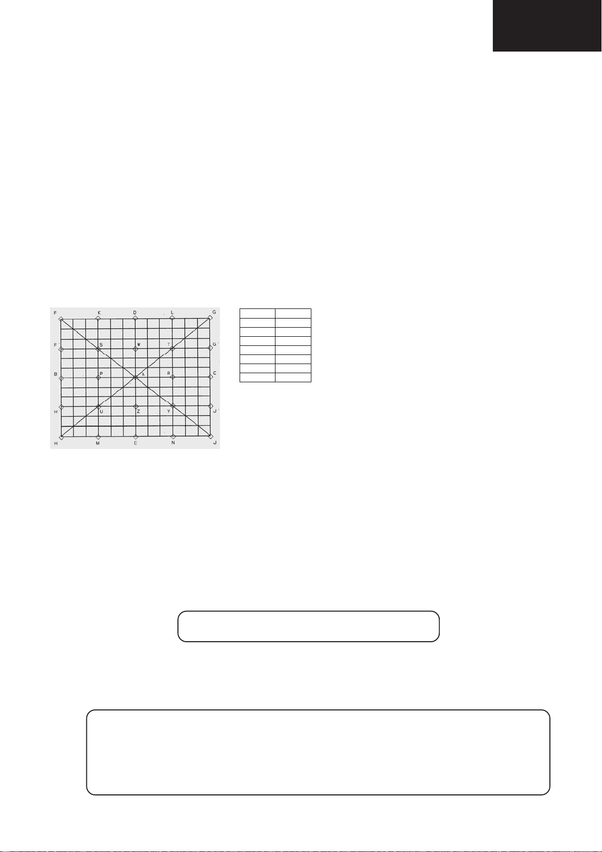
•Convergence (Maximum Misconvergence)
AREA 14”
A 0.3
BC 0.8
DE 0.8
FGHJ 1.3
KLMN 1.0
F’G’H’J’ 1.0
STUV 0.9
mm
•Picture Intermediate frequency
L’ ................................................ 33.9MHz
L, B/G, D/K .............................. 38.9MHz
•Sound Carrier Trap
L’ ................................................ 40.4MHz
L, D/K ......................................... 32.4MHz
B/G ............................................ 33.4MHz
•Adjacent Sound Carrier Trap
L’ ................................................ 32.4MHz
L, D/K, B/G ................................ 40.4MHz
•Adjacent Picture Carrier Trap
L’ ................................................ 41.9MHz
L, D/K ...................................... 30.9MHz
B/G ............................................ 31.9MHz
•Aerial Input Impedance
VHF/UHF ................. 75 ohm Unbalanced
•Tuning Ranges ..... 48.25MHz thru 855.25 MHz
VHF: S1 - S41 CH (Hiperband)
E2 - E12 / F2 - F10
UHF: E21 - E69
VHF: OIRT R1-R12
•White Level
Apply the rated voltage at the rated frequency to the TV set, while it is receiving full white pattern RF signal of 60
dB/μV from its RF input via the pattern generator.
Turn all picture controls to maximum value. Measure the colour temperatures at the center of the screen by
using the colour analyzer.
X=0.304 ± 0.015 Y=0.306 ± 0.015
Specifications are subject to change without prior notice.
WARNING
The chassis in this receiver is partially hot. Use an isolation transformer between the line cord plug
and power receptacle, when servicing this chassis.
To prevent electric shock, do not remove cover. No user-serviceable parts inside. Refer servicing to
qualified service personnel.
3
Page 4

14LM-40ERU
Only qualified service personnel are allowed to carry out maintenance and repair of this receiver.
Servicing of High Voltage System and CRT
It is important that the static charge is removed from the high voltage system when carrying out work on the
receiver. This can be achieved by connecting a 10K resistor (with a suitably insulated lead) from the CRT
cavity connector to the CRT ground tag. This must be carried out with the AC supply disconnected from the
receiver.
Note the following:
•
The CRT in this receiver employs Integral Implosion Protection.
• If the CRT has to be changed it MUST be replaced with the correct type for continued safe working.
• DO NOT lift the CRT by its neck.
• When handing the CRT, ensure that shatterproof goggles are worn.
• Ensure that the CRT is discharge before handling.
IMPORTANT SERVICING NOTES
X-Ray
This receiver is designed to keep any x-ray emission to an absolute minimum. Some fault conditions and
servicing procedures may produce potentially hazardous x-ray radiation levels. This is a problem when in
close proximity to the receiver for long periods of time. To reduce any risks associated with this, please
observe the following precautions:
1. When undertaking any servicing on this chassis, DO NOT increase the EHT to more than 27.5 KV, (at a
instantaneous beam current of 1000 μA).
2. Ensure that during normal operation the EHT does not exceed 23.1 KV (at a beam current of 800 μA). This
level has been preset in the factory. Always check that this level has not been exceeded after carrying out
any repair on the receiver.
3. DO NOT replace the CRT with any other type than that specified in the parts listing as this may cause
excessive x-ray radiation.
Before returning the receiver to the customer
In addition to the above checks, the following should also be carried out before returning the receiver to the
customer.
1. Inspect all the leads to ensure that they are dressed correctly and that they are not obstructed or pinched
by any other parts.
2. Ensure that all protective devices are in good condition. These will include nonmetallic control knobs,
insulating fish papers, cabinets backs, compartment covers or shields, mechanical insulators, etc.
4
Page 5

CONTROLS & TERMINALS
14LM-40ERU
Speaker
= Power On / Off
= Volume -/+
= Stand By
= Cursor Up
= Cursor Right
OK = OK
= Info (Program Menu)
0 - 9 = Direct Program
-/-- = Double Digit
= Wide mode button
P/CH+ = Program +
+ = Volume +
= TV / Quit Menu
(;7
= EXT button
(SCART, RGB)
Yellow = Feature Menu
Blue = Installation Menu
= Hold
= Update
= Index Page
= Reveal
= Expand
= Mix
= Teletext
= Time
Red = Sound Menu
Green = Picture Menu
= Mute
I-II = No function
- = - Volume
- P/CH = -Program
= Flash back button
M = Menu
= Cursor Down
= Cursor Left
0(18
REMOTE CONTROL
CH = Program -/+
MENU = Menu
5
Page 6

14LM-40ERU
Mother Unit
CHASSIS LAYOUT
CRT Unit
Front Unit
6
Page 7

14LM-40ERU
PARTS LISTING
Replacement parts which have special safety characteristics are identified in
this manual. Electrical components having such features are identified by
in the Replacement Parts Listing.
The use of a substitute replacement part which does not have the same safety
characteristics as the factory recommended is not permitted.
Replacement parts not shown in this service manual may create shock fire, or
other hazards.
To have your order completed promptly and correctly please supply the following information.
(*) When ordering any part, a “V” should be added before the Part No.
HOW TO ORDER REPLACEMENT P ARTS
1. MODEL NUMBER 2. REF. NO.
3. PART NO. (*) 4. DESCRIPTION
5. CODE 6. QUANTITY
(*)
REF No. PARTS DESCRIPTION SN CODE EX CODE
!
!
30002747 14" CRT TUBE SAFE RoHS BL CC
30042048 14"DEG COIL&EARTH CB. SAFE (SHARP) RoHS AG AR
TU201 30009637 TUNER WSP (PLL) CTF5510ARoHS AR BC
IC1 30001669 PREAMPLIFIER TFMS1380 RoHS AD AM
IC403 30026922 IC STV2248H (SHRINK56) ROHS AR BC
IC404 30001612 IC TDA2822M RoHS AD AN
IC500 20159398 IC 24C08 X67815030110122104(SHARP)
IC501 20170086 PR.IC.36/44-SHARP 36_44_B31 AS BD
IC600 30015306 IC TDA8174AW RoHS AD AN
IC810 30001668 IC LM317T ROHS RoHS AC AH
IC841 30034683 IC UC3842AN ROHS AC AH
IC842 30001622 IC 7805 (1A) RoHS AB AF
Q103 30001457 TR BC848B SMD RoHS AA AC
Q104 30001457 TR BC848B SMD RoHS AA AC
Q458 30001457 TR BC848B SMD RoHS AA AC
Q459 30001457 TR BC848B SMD RoHS AA AC
Q460 30001457 TR BC848B SMD RoHS AA AC
Q501 30001458 TR BC858B SMD RoHS AA AB
Q601 30013656 TR POWER STX112-AP ROHS AA AE
Q602 30001448 TR BU808DFI ROHS AF AQ
Q603 30001457 TR BC848B SMD RoHS AA AC
Q801 30001385 TR MTP3N60E (PLASTøK) RoHS AE AP
Q803 30001457 TR BC848B SMD RoHS AA AC
Q805 30014346 IC 78L05 TO-92 (100mA). RoHS AA AE
Q901 30001461 TR 2SC2482 ROHS AA AD
Q902 30001461 TR 2SC2482 ROHS AA AD
Q903 30001461 TR 2SC2482 ROHS AA AD
Q904 30001426 TR BF421 ROHS AA AD
Q905 30001426 TR BF421 ROHS AA AD
Q906 30001426 TR BF421 ROHS AA AD
D1 30001279 LED RED/GREEN LTL293SJ RoHS AC AH
D1 30001329 DIODE 1N4007 1A/1000V 30A ROHS AA AB
D102 30038472 DIODE ZENER SMD C5V1 SOD123 ROHS AA AA
D103 30038472 DIODE ZENER SMD C5V1 SOD123 ROHS AA AA
D104 30038472 DIODE ZENER SMD C5V1 SOD123 ROHS AA AA
D105 30038472 DIODE ZENER SMD C5V1 SOD123 ROHS AA AA
D106 30038472 DIODE ZENER SMD C5V1 SOD123 ROHS AA AA
D107 30038472 DIODE ZENER SMD C5V1 SOD123 ROHS AA AA
D108 30038476 DIODE ZENER C12V SMD SOD123 ROHS AA AA
D109 30038472 DIODE ZENER SMD C5V1 SOD123 ROHS AA AA
D110 30038472 DIODE ZENER SMD C5V1 SOD123 ROHS AA AA
D111 30038480 DIODE ZENER C5V6 SMD SOD123 ROHS AA AA
D402 30038472 DIODE ZENER SMD C5V1 SOD123 ROHS AA AA
D403 30001285 DIODE 1N4148 SMD ROHS AA AB
REPLACEMENT PARTS
PICTURE TUBE
TUNER
INTEGRATED CIRCUITS
TRANSISTORS
DIODES
REF No. PARTS DESCRIPTION SN CODE EX CODE
D406 30001285 DIODE 1N4148 SMD ROHS AA AB
D407 30001285 DIODE 1N4148 SMD ROHS AA AB
D410 30038477 DIODE ZENER C8V2 SMD SOD123 ROHS AA AA
D411 30038477 DIODE ZENER C8V2 SMD SOD123 ROHS AA AA
D412 30038477 DIODE ZENER C8V2 SMD SOD123 ROHS AA AA
D413 30038476 DIODE ZENER C12V SMD SOD123 ROHS AA AA
D414 30038476 DIODE ZENER C12V SMD SOD123 ROHS AA AA
D501 30001285 DIODE 1N4148 SMD ROHS AA AB
D502 30038479 DIODE ZENER SMD C3V6 SOD123 ROHS AA AA
D503 30001284 DIODE 1N4148 0.15A/100V 0.5A ROHS AA AB
D504 30001284 DIODE 1N4148 0.15A/100V 0.5A ROHS AA AB
D505 30001377 DIODE ZENER 33V UZT 33B ROHS AB AF
D601 30001329 DIODE 1N4007 1A/1000V 30A ROHS AA AB
D602 30001285 DIODE 1N4148 SMD ROHS AA AB
D604 30001318 DIODE BA159 1A/800V 20A ROHS AA AB
D605 30001318 DIODE BA159 1A/800V 20A ROHS AA AB
D606 30001318 DIODE BA159 1A/800V 20A ROHS AA AB
D609 30001284 DIODE 1N4148 0.15A/100V 0.5A ROHS AA AB
D610 30038476 DIODE ZENER C12V SMD SOD123 ROHS AA AA
D611 30030809 DIODE ZENER SMD BZT55B10V ROHS AA AA
D616 30000594 RES CF 1/4W 22K J. ROHS AA AB
D801 30001285 DIODE 1N4148 SMD ROHS AA AB
D802 30001318 DIODE BA159 1A/800V 20A ROHS AA AB
D803 30001331 DIODE 1N4937 1A/600V 30A ROHS AA AD
D804 30001288 DIODE BYV27-200 2A/200V 50A ROHS AA AD
D805 30001301 DIODE BYM26D 2.3A/800V 45-150A RoHS AB AF
D806 30001288 DIODE BYV27-200 2A/200V 50A ROHS AA AD
D811 30001318 DIODE BA159 1A/800V 20A ROHS AA AB
D813 30001318 DIODE BA159 1A/800V 20A ROHS AA AB
D837 30001318 DIODE BA159 1A/800V 20A ROHS AA AB
D838 30001318 DIODE BA159 1A/800V 20A ROHS AA AB
D839 30038472 DIODE ZENER SMD C5V1 SOD123 ROHS AA AA
D840 30001285 DIODE 1N4148 SMD ROHS AA AB
D841 30031925 DIODE BA159 1A/1000V DO214AC (SMD) ROHS AA AC
D842 30031925 DIODE BA159 1A/1000V DO214AC (SMD) ROHS AA AC
D901 30001284 DIODE 1N4148 0.15A/100V 0.5A ROHS AA AB
D902 30001284 DIODE 1N4148 0.15A/100V 0.5A ROHS AA AB
D903 30001284 DIODE 1N4148 0.15A/100V 0.5A ROHS AA AB
D904 Jumper Wire
D905 Jumper Wire
D906 Jumper Wire
D907 30000583 RES CF 1/4W 220R J ROHS AA AB
D908 30000583 RES CF 1/4W 220R J ROHS AA AB
D909 30000583 RES CF 1/4W 220R J ROHS AA AB
D910 30001318 DIODE BA159 1A/800V 20A ROHS AA AB
D911 30001318 DIODE BA159 1A/800V 20A ROHS AA AB
D912 30001318 DIODE BA159 1A/800V 20A ROHS AA AB
PACKAGED CIRCUITS
X401 30001749 XTAL 4.433619 Series HC49U ROHS AC AK
X402 30015592 XTAL 3.579545 (WO/LOAD CAP) ROHS AB AG
X501 30002851 XTAL 4.000 30p HC49U ROHS AC AH
COILS
L101 30001971 FERRITE SMD600R/100MHz200mA1.1R(805)ROHS AA AD
L107 30001734 JUMPER SMD (0805) ROHS AA AB
L108 30001734 JUMPER SMD (0805) ROHS AA AB
L109 30013412 FERRITE SMD1.5K/100MHz200mA0.4R(805)RoHS AA AA
L110 30013412 FERRITE SMD1.5K/100MHz200mA0.4R(805)RoHS AA AA
L111 30001971 FERRITE SMD600R/100MHz200mA1.1R(805)ROHS AA AD
L201 30001992 FIXEDCOIL AXI10uH500mAQ85K0.58R4x9.8ROHS AA AB
L202 30001971 FERRITE SMD600R/100MHz200mA1.1R(805)ROHS AA AD
L204 30001984 FIXEDCOIL AXI2.2uH230mAQ55M1.2R2.7x7ROHS AA AB
L205 30006712 FERRITE BEAD AXI 3.5x4.7x0.8 ROHS AA AB
L206 30001971 FERRITE SMD600R/100MHz200mA1.1R(805)ROHS AA AD
L207 30001971 FERRITE SMD600R/100MHz200mA1.1R(805)ROHS AA AD
L402 30001992 FIXEDCOIL AXI10uH500mAQ85K0.58R4x9.8ROHS AA AB
L403 30001990 FIXEDCOILAXI6.8uH550mAQ75K0.48R4x9.8ROHS AA AB
L404 30001987 FIXEDCOIL AXI4.7uH620mAQ70K0.4R4x9.8ROHS AA AB
L406 30001971 FERRITE SMD600R/100MHz200mA1.1R(805)ROHS AA AD
7
Page 8

14LM-40ERU
REF No. PARTS DESCRIPTION SN CODE EX CODE
L407 30001992 FIXEDCOIL AXI10uH500mAQ85K0.58R4x9.8ROHS AA AB
L408 30001971 FERRITE SMD600R/100MHz200mA1.1R(805)ROHS AA AD
L409 30001971 FERRITE SMD600R/100MHz200mA1.1R(805)ROHS AA AD
L410 30001992 FIXEDCOIL AXI10uH500mAQ85K0.58R4x9.8ROHS AA AB
L411 Jumper Wire
L602 Jumper Wire
!
L801 30031103 LINE FILTER SAFE 2*27MH RoHS AA AE
L802 30001971 FERRITE SMD600R/100MHz200mA1.1R(805)ROHS AA AD
L803 30001984 FIXEDCOIL AXI2.2uH230mAQ55M1.2R2.7x7ROHS AA AB
L804 30001971 FERRITE SMD600R/100MHz200mA1.1R(805)ROHS AA AD
L805 30001971 FERRITE SMD600R/100MHz200mA1.1R(805)ROHS AA AD
L806 30031101 FIXED COIL 150UH 0.82A RAD 8*12 RoHS AA AB
L810 30001971 FERRITE SMD600R/100MHz200mA1.1R(805)ROHS AA AD
L811 30001990 FIXEDCOILAXI6.8uH550mAQ75K0.48R4x9.8ROHS AA AB
CERAMIC FILTERS
Z401 30001728 TRIPLE TRAP TPT02B ROHS AG AT
Z403 30012544 FILTER SAW K2966 ROHS AH AU
TRANSFORMERS
!
TR601 30017788 TRF FBT SAFE 90(AK30-36 LAYER TYPE)RoHS AT BE
!
TR801 30015302 TRF SMPS SAFE AK36 90° (170-270V) RoHS AF AR
CAPACITORS
C1 30000371 CAP EL 22UF 50V M ROHS AA AB
C103 30000345 CAP EL 10UF 50V M ROHS AA AB
C104 30012591 CAP SMD 5.6NF 50V K (0603) ROHS AA AA
C109 30012589 CAP SMD 4.7NF 50V K (0603) ROHS AA AB
C110 30012589 CAP SMD 4.7NF 50V K (0603) ROHS AA AB
C111 30000345 CAP EL 10UF 50V M ROHS AA AB
C201 30000400 CAP EL 47UF 50V M ROHS AA AB
C203 30012985 JUMPER SMD 0603 ROHS AA AB
C206 30000371 CAP EL 22UF 50V M ROHS AA AB
C207 30012610 CAP SMD 10NF 50V J (0603) ROHS AA AB
C208 30012610 CAP SMD 10NF 50V J (0603) ROHS AA AB
C401 30000345 CAP EL 10UF 50V M ROHS AA AB
C402 30000289 CAP SMD 10NF 50V K R (0805) ROHS AA AB
C403 30012610 CAP SMD 10NF 50V J (0603) ROHS AA AB
C404 30016654 CAP SMD 100NF 16V K R (0603) ROHS AA AB
C405 30016654 CAP SMD 100NF 16V K R (0603) ROHS AA AB
C406 30012586 CAP SMD 22NF 50V K (0603) ROHS AA AB
C408 30000074 CAP MKT 100NF 63V J RoHS AA AC
C409 30000384 CAP EL 2.2UF 50V M ROHS AA AB
C411 30000074 CAP MKT 100NF 63V J RoHS AA AC
C412 30012586 CAP SMD 22NF 50V K (0603) ROHS AA AB
C413 30016654 CAP SMD 100NF 16V K R (0603) ROHS AA AB
C415 30000362 CAP EL 1UF 50V M. ROHS AA AB
C416 30012586 CAP SMD 22NF 50V K (0603) ROHS AA AB
C417 30000362 CAP EL 1UF 50V M. ROHS AA AB
C418 30000362 CAP EL 1UF 50V M. ROHS AA AB
C419 30000074 CAP MKT 100NF 63V J RoHS AA AC
C420 30000345 CAP EL 10UF 50V M ROHS AA AB
C421 30012581 CAP SMD 1NF 50V K R (0603) ROHS AA AB
C422 30000100 CAP MKT 330NF 63V J ROHS AA AD
C423 30012586 CAP SMD 22NF 50V K (0603) ROHS AA AB
C424 30000109 CAP MKT 470NF 63V J ROHS AA AD
C425 30000074 CAP MKT 100NF 63V J RoHS AA AC
C427 30000362 CAP EL 1UF 50V M. ROHS AA AB
C428 30000362 CAP EL 1UF 50V M. ROHS AA AB
C429 30012586 CAP SMD 22NF 50V K (0603) ROHS AA AB
C431 30016654 CAP SMD 100NF 16V K R (0603) ROHS AA AB
C432 30016654 CAP SMD 100NF 16V K R (0603) ROHS AA AB
C433 30016654 CAP SMD 100NF 16V K R (0603) ROHS AA AB
C434 30012586 CAP SMD 22NF 50V K (0603) ROHS AA AB
C435 30012585 CAP SMD 2.2NF 50V K R (0603) ROHS AA AB
C436 30007082 CAP MKT 680NF 63V J ROHS AA AD
C438 30000384 CAP EL 2.2UF 50V M ROHS AA AB
C440 30012589 CAP SMD 4.7NF 50V K (0603) ROHS AA AB
C441 30016654 CAP SMD 100NF 16V K R (0603) ROHS AA AB
C442 30000362 CAP EL 1UF 50V M. ROHS AA AB
REF No. PARTS DESCRIPTION SN CODE EX CODE
C443 30000345 CAP EL 10UF 50V M ROHS AA AB
C455 30000345 CAP EL 10UF 50V M ROHS AA AB
C458 30012567 CAP SMD 220PF 50V J (0603) ROHS AA AB
C459 30000345 CAP EL 10UF 50V M ROHS AA AB
C460 30000371 CAP EL 22UF 50V M ROHS AA AB
C465 30012575 CAP SMD 4.7PF 50V C CH (0603) ROHS AA AA
C466 30000345 CAP EL 10UF 50V M ROHS AA AB
C468 30012574 CAP SMD 470PF 50V J (0603) ROHS AA AA
C470 30000074 CAP MKT 100NF 63V J RoHS AA AC
C501 30000074 CAP MKT 100NF 63V J RoHS AA AC
C502 30000396 CAP EL 47UF 16V M ROHS AA AB
C503 30016654 CAP SMD 100NF 16V K R (0603) ROHS AA AB
C504 30012589 CAP SMD 4.7NF 50V K (0603) ROHS AA AB
C508 30012586 CAP SMD 22NF 50V K (0603) ROHS AA AB
C511 30000371 CAP EL 22UF 50V M ROHS AA AB
C512 30012586 CAP SMD 22NF 50V K (0603) ROHS AA AB
C516 30012586 CAP SMD 22NF 50V K (0603) ROHS AA AB
C518 30012560 CAP SMD 100PF 50V J (0603) ROHS AA AB
C519 30012562 CAP SMD 15PF 50V J (0603) ROHS AA AA
C520 30012562 CAP SMD 15PF 50V J (0603) ROHS AA AA
C522 30012985 JUMPER SMD 0603 ROHS AA AB
C523 30012566 CAP SMD 22PF 50V J (0603) ROHS AA AB
C526 30012589 CAP SMD 4.7NF 50V K (0603) ROHS AA AB
C529 30012586 CAP SMD 22NF 50V K (0603) ROHS AA AB
C532 30012586 CAP SMD 22NF 50V K (0603) ROHS AA AB
C534 Jumper Wire
C535 Jumper Wire
C538 30012560 CAP SMD 100PF 50V J (0603) ROHS AA AB
C539 30000400 CAP EL 47UF 50V M ROHS AA AB
C540 30000315 CAP SMD 220NF 25V Z (0805) ROHS AA AB
C541 30012590 CAP SMD 47NF 50V K (0603) ROHS AA AA
C542 30010571 CAP EL 10UF 16V M ROHS AA AA
C602 30000107 CAP MKT 47NF 250V J RoHS AA AD
C603 30000100 CAP MKT 330NF 63V J ROHS AA AD
C604 30018416 CAP EL 470UF 16V M 105° ROHS AA AB
C605 30000354 CAP EL 100UF 35V M ROHS AA AC
C606 30000092 CAP MKT 220NF 63V J ROHS AA AD
C607 30000078 CAP MKT 1UF 100V M ROHS AB AF
C609 30000371 CAP EL 22UF 50V M ROHS AA AB
C610 30000360 CAP EL 1000UF 25V M. RoHS AA AE
C611 30029804 CAPMKPSAFE12NF1600Vdc/1250Vpp%5RRoHS AB AF
C613 30000350 CAP EL 10UF 250V M. ROHS AA AD
C616 30000172 CAP MKP SAFE 680NF 250V J (P=15) ROHS AC AH
C617 30007750 CAP EL 470UF 35V (H/R 1150MA) ROHS AA AD
C618 30000092 CAP MKT 220NF 63V J ROHS AA AD
C619 30000384 CAP EL 2.2UF 50V M ROHS AA AB
C620 30000315 CAP SMD 220NF 25V Z (0805) ROHS AA AB
C641 30000345 CAP EL 10UF 50V M ROHS AA AB
C642 30012985 JUMPER SMD 0603 ROHS AA AB
C643 30000394 CAP EL 3.3UF 160V M ROHS AA AC
C644 30000345 CAP EL 10UF 50V M ROHS AA AB
C645 30000362 CAP EL 1UF 50V M. ROHS AA AB
C646 30012581 CAP SMD 1NF 50V K R (0603) ROHS AA AB
C647 30000116 CAP MKT 68NF 63V J ROHS AA AC
C648 30012609 CAP SMD 68NF 50V K (0603) ROHS AA AB
C649 30012573 CAP SMD 47PF 50V J (0603) ROHS AA AB
C650 30000294 CAP SMD 100NF 50V K (0805) ROHS AA AB
C651 30000294 CAP SMD 100NF 50V K (0805) ROHS AA AB
C652 30016126 CAP SMD 220NF 16V K R (0603) ROHS AA AB
!
C801 30000094 CAP MKT SAFE 220NF 275V M AC RoHS AA AB
!
C802 30000084 CAP MKT SAFE 150NF 275V M AC P=15 ROHS AC AG
C804 30007708 CAP CER 1NF 1KV K (PULSE) ROHS AA AD
C805 30012585 CAP SMD 2.2NF 50V K R (0603) ROHS AA AB
C806 30012581 CAP SMD 1NF 50V K R (0603) ROHS AA AB
C807 30000090 CAP MKT 22NF 100V J ROHS AA AB
C808 30000418 CAP EL 100UF 400V M ROHS AH AU
C810 30000315 CAP SMD 220NF 25V Z (0805) ROHS AA AB
C811 30000345 CAP EL 10UF 50V M ROHS AA AB
C812 30000161 CAP MKP SAFE 47NF 630Vdc / 622Vpp J ROHS AB AE
8
Page 9

14LM-40ERU
A
REF No. PARTS DESCRIPTION SN CODE EX CODE
C813 30007308 CAP CER 220PF 1KV K (PULSE) ROHS AA AD
!
C814 30000440 CAP CER SAFE 2.2NF 4KV M RoHS AA AC
C815 30000294 CAP SMD 100NF 50V K (0805) ROHS AA AB
C816 30013533 CAP CER 100PF 1KV K (PULSE) ROHS AA AC
C817 30000431 CAP CER 100PF 1KV M RoHS AA AC
C818 30000433 CAP CER 1NF 1KV M B ROHS AA AB
C819 30000382 CAP EL 2200UF 16V M ROHS AB AF
C820 30036924 CAP EL 100UF 200V M (HR) SHARP AK36 AC AH
C821 30000294 CAP SMD 100NF 50V K (0805) ROHS AA AB
C822 30018416 CAP EL 470UF 16V M 105° ROHS AA AB
C823 30000407 CAP EL 470UF 16V M. ROHS AA AC
C824 30000352 CAP EL 100UF 16V M ROHS AA AB
C825 30000352 CAP EL 100UF 16V M ROHS AA AB
C826 30000092 CAP MKT 220NF 63V J ROHS AA AD
C827 30006909 CAP EL 100UF M 250V ROHS AC AG
C829 30012586 CAP SMD 22NF 50V K (0603) ROHS AA AB
!
C836 30000440 CAP CER SAFE 2.2NF 4KV M RoHS AA AC
C839 30000294 CAP SMD 100NF 50V K (0805) ROHS AA AB
C840 30000294 CAP SMD 100NF 50V K (0805) ROHS AA AB
C841 30000345 CAP EL 10UF 50V M ROHS AA AB
C842 30012586 CAP SMD 22NF 50V K (0603) ROHS AA AB
C905 30000213 CAP CER 180PF 50V J CH RoHS AA AB
C907 30000213 CAP CER 180PF 50V J CH RoHS AA AB
C909 30000213 CAP CER 180PF 50V J CH RoHS AA AB
C910 30000434 CAP CER 1NF 2KV K B ROHS AA AB
C915 30000266 CAP CER 560PF 50V J SL ROHS AA AB
C916 30000266 CAP CER 560PF 50V J SL ROHS AA AB
C917 30000266 CAP CER 560PF 50V J SL ROHS AA AB
C918 30000266 CAP CER 560PF 50V J SL ROHS AA AB
C919 30000266 CAP CER 560PF 50V J SL ROHS AA AB
C920 30000266 CAP CER 560PF 50V J SL ROHS AA AB
C921 30000436 CAP CER 10NF 1KV ZE ROHS AA AC
C923 30000436 CAP CER 10NF 1KV ZE ROHS AA AC
RESISTORS
R1 Jumper Wire
R1 30001123 RES MO 2W 220R J ROHS AA AC
R101 30012509 RES SMD 1/16W 100K J (0603) ROHS AA AB
R110 30012713 RES SMD 1/16W 75R J (0603) ROHS AA AB
R111 30012713 RES SMD 1/16W 75R J (0603) ROHS AA AB
R113 30012713 RES SMD 1/16W 75R J (0603) ROHS AA AB
R115 30012713 RES SMD 1/16W 75R J (0603) ROHS AA AB
R117 30012986 RES SMD 1/16W 68R J (0603) ROHS AA AA
R118 30012713 RES SMD 1/16W 75R J (0603) ROHS AA AB
R119 30012713 RES SMD 1/16W 75R J (0603) ROHS AA AB
R122 30012713 RES SMD 1/16W 75R J (0603) ROHS AA AB
R123 30012713 RES SMD 1/16W 75R J (0603) ROHS AA AB
R125 30012713 RES SMD 1/16W 75R J (0603) ROHS AA AB
R126 30012695 RES SMD 1/16W 470R J (0603) ROHS AA AB
R127 30012713 RES SMD 1/16W 75R J (0603) ROHS AA AB
R128 30012510 RES SMD 1/16W 100R J (0603) ROHS AA AB
R129 30012641 RES SMD 1/16W 10K J (0603) ROHS AA AB
R130 30012641 RES SMD 1/16W 10K J (0603) ROHS AA AB
R131 30012985 JUMPER SMD 0603 ROHS AA AB
R132 30012985 JUMPER SMD 0603 ROHS AA AB
R2 30000526 RES CF 1/4W 1.5K J ROHS AA AB
R201 30012674 RES SMD 1/16W 27K J (0603) ROHS AA AB
R203 30000583 RES CF 1/4W 220R J ROHS AA AB
R204 30012692 RES SMD 1/16W 4.7K J (0603) ROHS AA AB
R206 30000583 RES CF 1/4W 220R J ROHS AA AB
R3 30000689 RES CF 1/4W 3.9K J ROHS AA AB
R4 30000712 RES CF 1/4W 470R J RoHS AA AB
R401 30014076 RES SMD 1/16W 4.7R J (0603) ROHS AA AA
R402 30014076 RES SMD 1/16W 4.7R J (0603) ROHS AA AA
R408 30000466 RES CF 1/4W 1K J ROHS AA AB
R409 30012510 RES SMD 1/16W 100R J (0603) ROHS AA AB
R410 30012707 RES SMD 1/16W 680R J (0603) ROHS AA AB
R411 30012657 RES SMD 1/16W 1K J (0603) ROHS AA AB
R412 30012667 RES SMD 1/16W 220K J (0603) ROHS AA AB
REF No. PARTS DESCRIPTION SN CODE EX CODE
R413 30000712 RES CF 1/4W 470R J RoHS AA AB
R414 30012649 RES SMD 1/16W 150R J (0603) ROHS AA AB
R415 30012683 RES SMD 1/16W 330K J (0603) ROHS AA AB
R416 30012713 RES SMD 1/16W 75R J (0603) ROHS AA AB
R417 30012650 RES SMD 1/16W 15K J (0603) ROHS AA AB
R418 30012510 RES SMD 1/16W 100R J (0603) ROHS AA AB
R419 30012510 RES SMD 1/16W 100R J (0603) ROHS AA AB
R420 30000466 RES CF 1/4W 1K J ROHS AA AB
R421 30012674 RES SMD 1/16W 27K J (0603) ROHS AA AB
R422 30012641 RES SMD 1/16W 10K J (0603) ROHS AA AB
R423 30012714 RES SMD 1/16W 820R J (0603) ROHS AA AA
R424 30012714 RES SMD 1/16W 820R J (0603) ROHS AA AA
R425 30012714 RES SMD 1/16W 820R J (0603) ROHS AA AA
R426 30000718 RES CF 1/4W 4.7K J ROHS AA AB
R427 30000717 RES SMD 1/10W 470R J (0805) RoHS AA AB
R428 30012696 RES SMD 1/16W 47K J (0603) ROHS AA AB
R429 30000466 RES CF 1/4W 1K J ROHS AA AB
R430 30000466 RES CF 1/4W 1K J ROHS AA AB
R431 30000466 RES CF 1/4W 1K J ROHS AA AB
R432 30000590 RES CF 1/4W 2.2K J. ROHS AA AB
R433 30000712 RES CF 1/4W 470R J RoHS AA AB
R434 30012657 RES SMD 1/16W 1K J (0603) ROHS AA AB
R435 30012659 RES SMD 1/16W 2.2K J (0603) ROHS AA AB
R436 30012674 RES SMD 1/16W 27K J (0603) ROHS AA AB
R437 30012642 RES SMD 1/16W 120K J (0603) ROHS AA AA
R460 30012698 RES SMD 1/16W 5.6K J (0603) ROHS AA AB
R469 30012683 RES SMD 1/16W 330K J (0603) ROHS AA AB
R470 30000670 RES CF 1/4W 330K J. ROHS AA AB
R474 30000748 RES CF 1/4W 5.6K J RoHS AA AB
R477 30012662 RES SMD 1/16W 2.7K J (0603) ROHS AA AB
R478 30014022 RES SMD 1/16W 47R J (0603) ROHS AA AA
R479 30012510 RES SMD 1/16W 100R J (0603) ROHS AA AB
R480 30012510 RES SMD 1/16W 100R J (0603) ROHS AA AB
R481 30012510 RES SMD 1/16W 100R J (0603) ROHS AA AB
R482 30012657 RES SMD 1/16W 1K J (0603) ROHS AA AB
R5 30000770 RES CF 1/4W 680R J ROHS AA AB
R503 30012707 RES SMD 1/16W 680R J (0603) ROHS AA AB
R507 30012657 RES SMD 1/16W 1K J (0603) ROHS AA AB
R508 30014022 RES SMD 1/16W 47R J (0603) ROHS AA AA
R509 30012641 RES SMD 1/16W 10K J (0603) ROHS A
R510 30012673 RES SMD 1/16W 270R J (0603) ROHS AA AB
R511 30012508 RES SMD 1/16W 1.8K J (0603) ROHS AA AB
R512 30000459 RES CF 1/4W 100R J. ROHS AA AB
R513 30000459 RES CF 1/4W 100R J. ROHS AA AB
R514 30012657 RES SMD 1/16W 1K J (0603) ROHS AA AB
R515 30012692 RES SMD 1/16W 4.7K J (0603) ROHS AA AB
R516 30012692 RES SMD 1/16W 4.7K J (0603) ROHS AA AB
R517 30012692 RES SMD 1/16W 4.7K J (0603) ROHS AA AB
R520 30012698 RES SMD 1/16W 5.6K J (0603) ROHS AA AB
R526 30012985 JUMPER SMD 0603 ROHS AA AB
R528 30012668 RES SMD 1/16W 220R J (0603) ROHS AA AA
R529 30000590 RES CF 1/4W 2.2K J. ROHS AA AB
R531 30012698 RES SMD 1/16W 5.6K J (0603) ROHS AA AB
R533 30012698 RES SMD 1/16W 5.6K J (0603) ROHS AA AB
R534 30000500 RES CF 1/4W 12K J. ROHS AA AB
R535 30012506 RES SMD 1/16W 1.5K J (0603) ROHS AA AB
R537 30000471 RES CF 1/4W 10K J ROHS AA AB
R541 30000500 RES CF 1/4W 12K J. ROHS AA AB
R542 30012508 RES SMD 1/16W 1.8K J (0603) ROHS AA AB
R546 30012692 RES SMD 1/16W 4.7K J (0603) ROHS AA AB
R547 30012641 RES SMD 1/16W 10K J (0603) ROHS AA AB
R549 30012692 RES SMD 1/16W 4.7K J (0603) ROHS AA AB
R560 30000525 RES CF 1/2W 1.5K J ROHS AA AB
R561 30012985 JUMPER SMD 0603 ROHS AA AB
R564 30012641 RES SMD 1/16W 10K J (0603) ROHS AA AB
R565 30012641 RES SMD 1/16W 10K J (0603) ROHS AA AB
R568 30000459 RES CF 1/4W 100R J. ROHS AA AB
R6 30000622 RES CF 1/4W 270R J RoHS AA AB
R601 30000723 RES CF 1/4W 47K J ROHS AA AB
AB
9
Page 10

14LM-40ERU
(
)
REF No. PARTS DESCRIPTION SN CODE EX CODE
R602 30012642 RES SMD 1/16W 120K J (0603) ROHS AA AA
R603 30012711 RES SMD 1/16W 75K J (0603) ROHS AA AA
R604 30000718 RES CF 1/4W 4.7K J ROHS AA AB
R605 30012641 RES SMD 1/16W 10K J (0603) ROHS AA AB
R607 30015578 RES SMD 1/16W 2.2R J (0603) ROHS AA AA
R608 30000597 RES SMD 1/10W 22K J ROHS AA AB
R609 30001146 RES MO 2W 33R J ROHS AA AB
R610 30000519 RES CF 1/4W 150R J. ROHS AA AB
R611 Jumper Wire
R612 30012508 RES SMD 1/16W 1.8K J (0603) ROHS AA AB
R613 30000828 RES CF 1/4W 8.2M J ROHS AA AB
R614 30000471 RES CF 1/4W 10K J ROHS AA AB
R615 30012510 RES SMD 1/16W 100R J (0603) ROHS AA AB
R616 30001146 RES MO 2W 33R J ROHS AA AB
R617 30012677 RES SMD 1/16W 3.3K J (0603) ROHS AA AA
R618 30000769 RES CF 1/2W 680R J. ROHS AA AB
R619 30000910 RES MF 1/2W 1.8R G ROHS AA AB
R620 30012692 RES SMD 1/16W 4.7K J (0603) ROHS AA AB
R623 30000869 RES MF 1/4W 12K J ROHS AA AB
R624 30000594 RES CF 1/4W 22K J. ROHS AA AB
R625 30000466 RES CF 1/4W 1K J ROHS AA AB
!
R626 30001227 RES FUSE SAFE 1W 0.22R J RoHS AA AC
R627 30000660 RES CF 1/4W 3.3K J. ROHS AA AB
R628 30014941 RES CF 1/4W 16K J ROHS AA AA
R631 30012508 RES SMD 1/16W 1.8K J (0603) ROHS AA AB
R632 30012641 RES SMD 1/16W 10K J (0603) ROHS AA AB
R633 30000564 RES CF 1/4W 18K J. ROHS AA AB
R634 30012692 RES SMD 1/16W 4.7K J (0603) ROHS AA AB
R635 30012659 RES SMD 1/16W 2.2K J (0603) ROHS AA AB
R636 30001162 RES MO 1W 390R J ROHS AA AB
R637 Jumper Wire
R638 30001192 RES MO 1W 680R J ROHS AA AB
R640 30002731 RES SMD 1/10W 68R J ROHS AA AB
R641 30012641 RES SMD 1/16W 10K J (0603) ROHS AA AB
R801 30000983 RES MF 1/4W 4.7K F ROHS AA AB
R802 30012642 RES SMD 1/16W 120K J (0603) ROHS AA AA
R803 30007207 RES SMD 1/10W 22K F ROHS AA AA
R804 30000466 RES CF 1/4W 1K J ROHS AA AB
R805 30000466 RES CF 1/4W 1K J ROHS AA AB
R807 30003638 RES MO 1W 270K J ROHS AA AA
R808 30000452 RES CF 1/4W 10R J. ROHS AA AB
R809 30001201 RES MO 2W 75K J AA AA
R810 30017136 RES MO 1W 0.56R J ROHS AA AA
R811 30001257 RES MG SAFE 1/2W 4.7M J ROHS AA AD
R813 30000470 RES CF 1/2W 10K J ROHS AA AA
R814 30000649 RES CF 1/2W 33R J. ROHS AA AB
R815 30000524 RES SMD 1/10W 150R J (0805) ROHS AA AB
R816 30000470 RES CF 1/2W 10K J ROHS AA AA
R817 30000594 RES CF 1/4W 22K J. ROHS AA AB
R820 30000469 RES SMD 1/10W 1K J 0805 ROHS AA AB
R821 30001215 RES FUSE SAFE 1W 1R J ROHS AA AC
R828 Jumper Wire
R829 30012714 RES SMD 1/16W 820R J (0603) ROHS AA AA
R830 30001245 RES FUSE SAFE 1/4W 0.47R J ROHS AA AC
R831 30012677 RES SMD 1/16W 3.3K J (0603) ROHS AA AA
R832 30018085 CAP VAR SAFE 510V K MFCN14D511 ROHS AA AD
R833 20187584 MD.ASY.KTL36-11KTL36 AB AF
R901 30000683 RES CF 1/4W 390R J ROHS AA AB
R902 30000683 RES CF 1/4W 390R J ROHS AA AB
R903 30000683 RES CF 1/4W 390R J ROHS AA AB
R904 30000560 RES CF 1/4W 1.8K J ROHS AA AB
R905 30000560 RES CF 1/4W 1.8K J ROHS AA AB
R906 30000560 RES CF 1/4W 1.8K J ROHS AA AB
R907 30000706 RES CF 1/4W 47R J ROHS AA AB
R908 30000706 RES CF 1/4W 47R J ROHS AA AB
R909 30000706 RES CF 1/4W 47R J ROHS AA AB
R910 30000655 RES CF 1/4W 330R J. ROHS AA AB
R911 30000655 RES CF 1/4W 330R J. ROHS AA AB
R912 30000655 RES CF 1/4W 330R J. ROHS AA AB
REF No. PARTS DESCRIPTION SN CODE EX CODE
R913 30001105 RES MO 1W 15K J ROHS AA AB
R914 30001105 RES MO 1W 15K J ROHS AA AB
R915 30001105 RES MO 1W 15K J ROHS AA AB
R916 30000660 RES CF 1/4W 3.3K J. ROHS AA AB
R917 30000660 RES CF 1/4W 3.3K J. ROHS AA AB
R918 30000660 RES CF 1/4W 3.3K J. ROHS AA AB
R919 30000526 RES CF 1/4W 1.5K J ROHS AA AB
R920 30000526 RES CF 1/4W 1.5K J ROHS AA AB
R921 30000526 RES CF 1/4W 1.5K J ROHS AA AB
R925 30000526 RES CF 1/4W 1.5K J ROHS AA AB
PRINTED WIRING BOARD MODULES
Not Replacement Item
20228935 CHS.ASSY.36-161S11142118V (Mother Unit+CRT Unit) BE BV
20148313 MD.ASY.TP46I-8 IRICO (AK30/36) (RC-LED Unit) AG AS
MISCELLANEOUS PARTS
!
F801 30001731 FUSE SAFE 2.5A 250V 5*20MM AA AC
B-B A-A 30009832 CABL 1P/130 SISRoHS AA AB
J100 Jumper Wire
J103 30001984 FIXEDCOIL AXI2.2uH230mAQ55M1.2R2.7x7ROHS AA AB
J104 Jumper Wire
J105 Jumper Wire
J108 Jumper Wire
J112 Jumper Wire
J113 Jumper Wire
J114 Jumper Wire
J115 Jumper Wire
J118 Jumper Wire
J119 Jumper Wire
J123 Jumper Wire
J125 Jumper Wire
J126 Jumper Wire
J128 30002002 FIXEDCOIL AXI47uH340mAQ60K1.22R4x9.8RoHS AA AB
J132 Jumper Wire
J135 Jumper Wire
J136 Jumper Wire
J137 Jumper Wire
J138 Jumper Wire
J139 Jumper Wire
J141 Jumper Wire
J142 30000459 RES CF 1/4W 100R J. ROHS AA AB
J145 Jumper Wire
J148 Jumper Wire
J149 Jumper Wire
J153 Jumper Wire
J154 Jumper Wire
J155 30012985 JUMPER SMD 0603 ROHS AA AB
J157 Jumper Wire
J158 Jumper Wire
J160 Jumper Wire
J161 Jumper Wire
J162 Jumper Wire
J163 Jumper Wire
J165 Jumper Wire
J166 Jumper Wire
J167 30006712 FERRITE BEAD AXI 3.5x4.7x0.8 ROHS AA AB
J168 30001992 FIXEDCOIL AXI10uH500mAQ85K0.58R4x9.8ROHS AA AB
J173 Jumper Wire
J174 Jumper Wire
J176 Jumper Wire
J177 Jumper Wire
J178 Jumper Wire
J180 Jumper Wire
J181 Jumper Wire
J182 30012985 JUMPER SMD 0603 ROHS AA AB
J183 Jumper Wire
J184 30012985 JUMPER SMD 0603 ROHS AA AB
J186 30012985 JUMPER SMD 0603 ROHS AA AB
J187 Jumper Wire
10
Page 11

14LM-40ERU
REF No. PARTS DESCRIPTION SN CODE EX CODE
J191 Jumper Wire
J192 Jumper Wire
J194 Jumper Wire
J194 Jumper Wire
J195 Jumper Wire
J195 Jumper Wire
J196 30012985 JUMPER SMD 0603 ROHS AA AB
J197 30012985 JUMPER SMD 0603 ROHS AA AB
J198 Jumper Wire
J200 Jumper Wire
J201 Jumper Wire
J202 30012985 JUMPER SMD 0603 ROHS AA AB
J207 Jumper Wire
J208 Jumper Wire
J210 Jumper Wire
J221 Jumper Wire
J222 30012985 JUMPER SMD 0603 ROHS AA AB
J223 Jumper Wire
J224 30012985 JUMPER SMD 0603 ROHS AA AB
J225 Jumper Wire
J228 Jumper Wire
J230 Jumper Wire
J233 30012985 JUMPER SMD 0603 ROHS AA AB
J234 30012985 JUMPER SMD 0603 ROHS AA AB
J235 30012985 JUMPER SMD 0603 ROHS AA AB
J237 30012985 JUMPER SMD 0603 ROHS AA AB
J238 30012985 JUMPER SMD 0603 ROHS AA AB
J239 30012985 JUMPER SMD 0603 ROHS AA AB
J240 30012985 JUMPER SMD 0603 ROHS AA AB
J245 30012985 JUMPER SMD 0603 ROHS AA AB
J246 30012985 JUMPER SMD 0603 ROHS AA AB
L901 Jumper Wire
P-H 30009846 CABL 1P/40 SISRoHS AA AB
PL1 30016521 CNAS 2P/150 TB FLT W/C W/UL2468AWG24RoHS AA AE
PL102 30015053 SOCKET SCART NEW TYPE RoHS AB AF
PL2 30002243 CNAS 5P/220 FLT UL2468 AWG24 ROHS AA AE
PL2 30009846 CABL 1P/40 SISRoHS AA AB
PL403 30031051 CONN HEADER 2P 2.5MM TOP WHT SD RoHS AA AA
PL404 30018456 CNAS 5P/300 SIS W/C+BRT UL1007AWG24RoHS AB AF
PL504 30001783 CONN HEADER 5P 2.5MM TOP GRAY BD AA AC
PL506 30031051 CONN HEADER 2P 2.5MM TOP WHT SD RoHS AA AA
PL507 30019101 CABL 1P/350 DIS UL1672AWG22 RoHS AA AB
PL508 30007732 CNAS 1P/300 AQUA DIS W/CLIPS AA AB
PL509 30031582 CONN HEADER 5P 2.5MM TOP WHT SD RoHS AA AA
PL601 30031051 CONN HEADER 2P 2.5MM TOP WHT SD RoHS AA AA
PL602 30018455 CNAS 3P-4/300 SIS W/C+BRTUL1007AWG24RoHS AA AE
PL603 30031046 CONN HEADER SAFE 2P(V0)7.5MM TOP WHTRoHS AA AA
PL802 30031046 CONN HEADER SAFE 2P(V0)7.5MM TOP WHTRoHS AA AA
PL803 30031050 CONN HEADER SAFE3P(V0)5/7.5MM TOPWHTRoHS AA AA
PL901 30031582 CONN HEADER 5P 2.5MM TOP WHT SD RoHS AA AA
PL902 30001857 SOCKET CRT SAFE B12-262 RoHS AF AR
S1 Jumper Wire
S102 30012985 JUMPER SMD 0603 ROHS AA AB
S203 30012985 JUMPER SMD 0603 ROHS AA AB
S406 30012985 JUMPER SMD 0603 ROHS AA AB
S407 30012985 JUMPER SMD 0603 ROHS AA AB
S408 30012985 JUMPER SMD 0603 ROHS AA AB
S410 Jumper Wire
S508 30012985 JUMPER SMD 0603 ROHS AA AB
S804 30012985 JUMPER SMD 0603 ROHS AA AB
SW1 30032684 SWITCH TACT(4) ROHS AA AA
SW2 30032684 SWITCH TACT(4) ROHS AA AA
SW3 30032684 SWITCH TACT(4) ROHS AA AA
SW4 30032684 SWITCH TACT(4) ROHS AA AA
SW5 30032684 SWITCH TACT(4) ROHS AA AA
SW801 30017848 SWITCH SAFE ON/OFF 4A/128A JVC(PAN)RoHS AC AH
TH800 30001270 PTC SAFE 9 OHM RoHS AC AK
VL405 30026042 ADJ.COIL VIF 44MHZ Q=64 C=39pF RoHS AA AD
30001954 SPEAKER 16R 3W 3'' AE AP
REF No. PARTS DESCRIPTION SN CODE EX CODE
!
!
!
30027591 CNAS 2P/350 SPK 90° DIS W/C AWG24 RoHS AA AD
20140518 BACK CVR.1462 EKO2GRAY (I) AH AT
20140991 BUTTON ASSY 1462(FUNC.SILV-ON/OF O.BLUE) AB AF
20152042 BUTTON ON/OFF 1462 OCEAN BLUE(P) AC AK
35008861 SPRING ON/OFF SWITCH 1462 SHARP(SHARP) AA AA
40024077 FOOT RUBBER 3730/31/40/4120141192 SNOW BOX ASSY 1462 (SHARP) AC AH
20141193 SCR.ASSY.1462 gr AB AF
20151304 PWR CORDASSY.(2.2MT W/FTZ)(LONGWELL)SAFE AD AM
20152039 FRONT 1462 W/H WO/J SLV285S(P) AP AZ
20067215 PCB GUIDE RAIL (HIGH SMALL)
40017363 CABLE HOLDER 2162_SF SHARP AA AC
40024075 CABLE HOLDER CRT (I) AA AA
40024080 PCB GUIDE RAIL (HIGH BIG) (I) AA AC
40026851 BRACKET POWER SWITCH (I
40026990 PW&AK36 BRAKETI (I)
20152095 MD.ASY.TK140-WO/HP 5SW 1462 AK36 AF AR
30017782 CNAS SAFE 2P/350 HRZ DIS W/C UL1672AWG24 AA AD
30032022 CNAS 2P/400 SIS W/C+FER UL1007AWG24 RoHS AA AE
35000014 EARTH SPRING (2CM) AA AB
50064760 CARTON BOX SHARP SHARP (1462)(2) AF AR
35000136 FUSE HOLDER SAFE TK79-A (GRAY)RoHS AA AD
40026380 FIRE BARRIER (I)(NATURAL-V.0) (AK36).
20143026 R/C 1548 SHARP (EKO2GRAY/I) (GRAY/S) AM AY
20142231 R/C KIT 1548 SHARP AN AY
50075280 I/B SHARP 14LM-40E(RU) 92195/1548/EN/RU AA AB
30002005 FIXED COIL 65UH 4A RAD 8*12 ROHS AA AE
40016816 LOGO SHARP (W/P-SøLVER BRUSH-HST) SMALL AB AF
How to update the Technical Information
appeared on this Service Manual
1. Web site: https://www.vestelservice.com
2. Select: Technical Support
3. User Name: 101278
4. Password: SHPII278
By this access you can consult the latest schematic diagram or request the Parts Listing of a concrete Production Date / Serial Number.
By this way it can be also consulted the issued Technical Reports (Service Bulletins).
11
Page 12

14LM-40ERU
COPYRIGHT © 2006 BY SHARP CORPORATION
No part of this publication may be reproduced,
stored in a retrieval system, or transmitted in any
form or by any means, electronic, mechanical,
photocopying, recording, or otherwise, without
prior written permission of the publisher.
Technical information and Production:
Vestel Electronik AS
ALL RIGHTS RESERVED.
Technical information re-issued:
SHARP ELECTRONICA ESPAÑA S.A.
Service Manual Group
Engineering Dept.
Polígono Industrial Can Sant Joan
08190 Sant Cugat del Vallès
Barcelona
Spain
Think Ecology, please use
RECYCLED PAPER
12
 Loading...