

Page 1

Page 2

CONTENTS
DESCRIPTION PAGE
Instalation----------------------------------------------------------------------Foundation---------------------------------------------------------------------Lifting the machine-----------------------------------------------------------Cleaning------------------------------------------------------------------------Leveling------------------------------------------------------------------------Inspection----------------------------------------------------------------------Lubrication---------------------------------------------------------------------Vertical lubrication-----------------------------------------------------------Carriage lubrication----------------------------------------------------------Gear box & clutch lubrication----------------------------------------------Headstock lubrication-------------------------------------------------------Electrical connections-------------------------------------------------------Spindle control levers--------------------------------------------------------Free spindle-------------------------------------------------------------------Quick change gear box------------------------------------------------------Auto thread length control--------------------------------------------------Spindle brake-----------------------------------------------------------------Brake adjustment------------------------------------------------------------Brake replacement-----------------------------------------------------------Belt adjustment---------------------------------------------------------------Collet closer removal--------------------------------------------------------Replace the collet closer----------------------------------------------------Collet closer adjustment----------------------------------------------------Carriage indicating ring----------------------------------------------------Carriage lock-----------------------------------------------------------------Carriage clutches------------------------------------------------------------Cross slide indicating ring-------------------------------------------------Quick action tool post compound slide assembly----------------------Power feed unit--------------------------------------------------------------Coolant-----------------------------------------------------------------------Tailstock assembly----------------------------------------------------------Tailstock spindle lock-------------------------------------------------------Tailstock lock----------------------------------------------------------------Thread cutting---------------------------------------------------------------Outside change gears-------------------------------------------------------English threads (Outside change gears)----------------------------------Metric threads (Outside change gears)-----------------------------------DVS Pictures-----------------------------------------------------------------Conversion table surface speed to R. P. M.-----------------------------Thread charts-----------------------------------------------------------------
2
2
2
3
3
4
4
4
5
5
5
5
6
6
7
7
8
8
8
9
9
9
10
10
10
10
11
11
11
12
12
12
12
13
14
15
16
18-20
21
22-27
Page 3
This manual has been specifically written for the SHARP 1118H precision tool room
lathe.
This manual will help you obtain the best results and accuracy from the lathe.
In order to provide the best possible product we are continuously conducting research and
development to improve our prod uct, therefore improvements in desig n and
specifications may change at any time without notice.
This manual applies only to the machine with which it is issued.
The serial number of your machine is:______________
1
Page 4
INSTALLATION
1. Foundation:
In order to achieve the accuracy from the 1118H TOOLROOM LATHE, it is
essential that the machine be installed on a solid concrete base t o eliminate any
possible vibration and be properly leveled. Should the machine be used free-standing
it is important to check regularly to be sure the machine is level
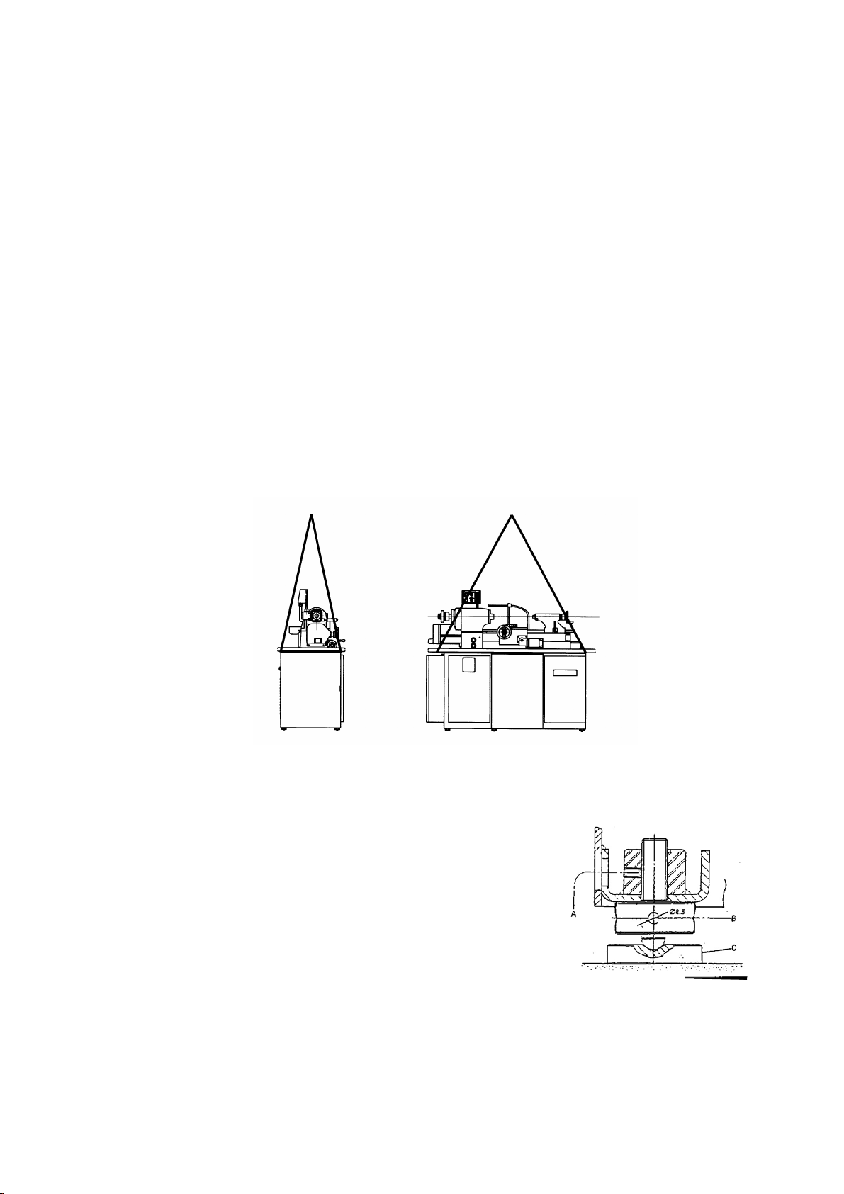
2. Lifting the machine:
The gross weight of the lathe is approxim ately 830kgs. This should be taken into
consideration when choosing the equipment for lifting the lathe.
It is recommended that the machine be lifted using a rope or cable placed ar o u nd the
bedpan as shown in Fig. A. The carriage s h ould be moved towards the tailstock for
balance and padding put between the edges of the ma chine and the rope or cable.
2
Page 5
3. Cleaning:
Each lathe is coated with a rust proofing grease prior to shipping. This grease should
be removed with white spirit or kerosen e before moving the cross slide, carriage or
tailstock. DO NOT USE CELLULOSE SOLVENTS FOR CLEANING AS IT WILL
DAMAGE THE PAINT.
When cleaning, pay particular attention to the slides and spindle nose. It is important
that the end guard is removed. After cleani ng, all parts should be dried with a soft
cloth and coated with a thin film of oil .
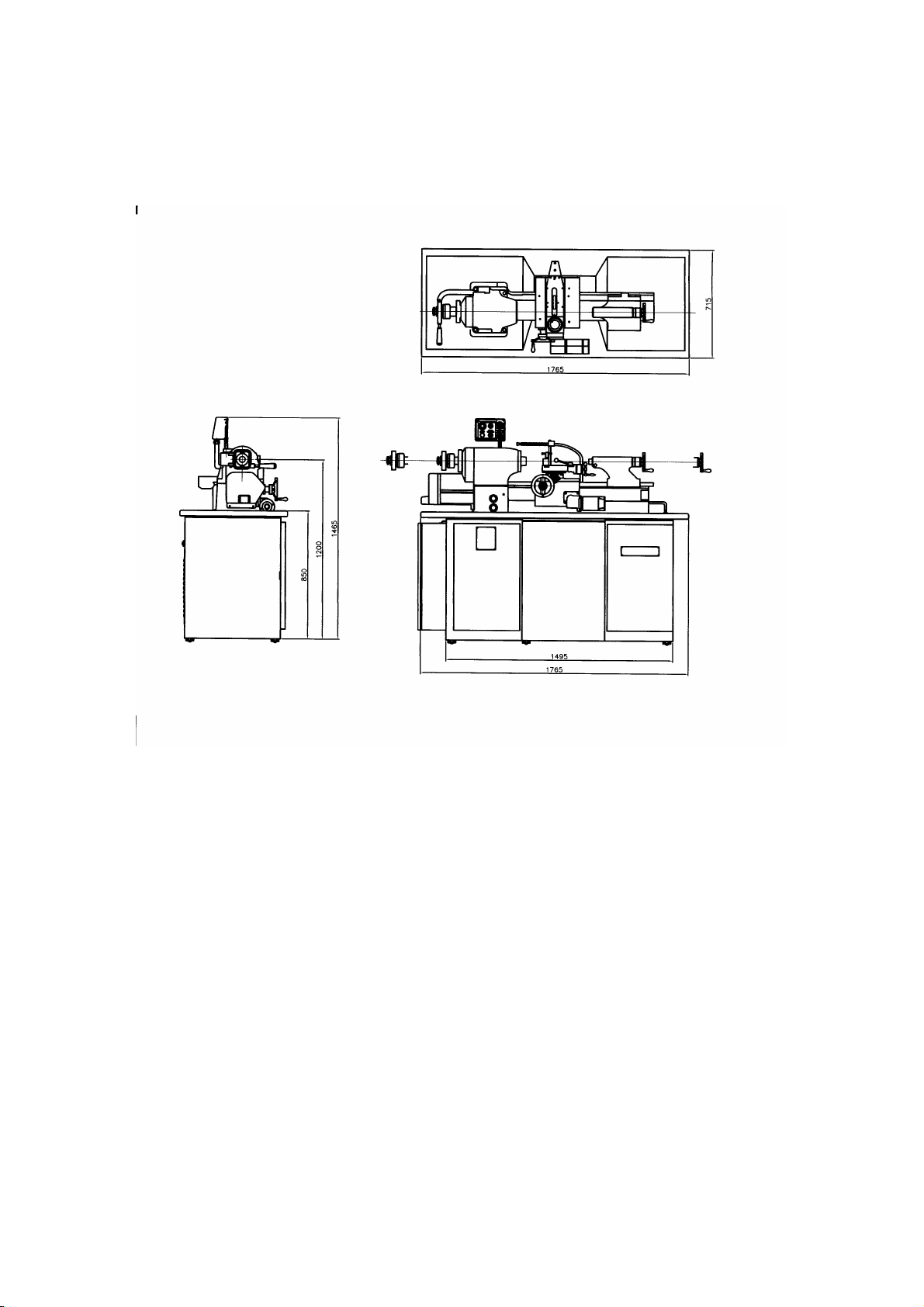
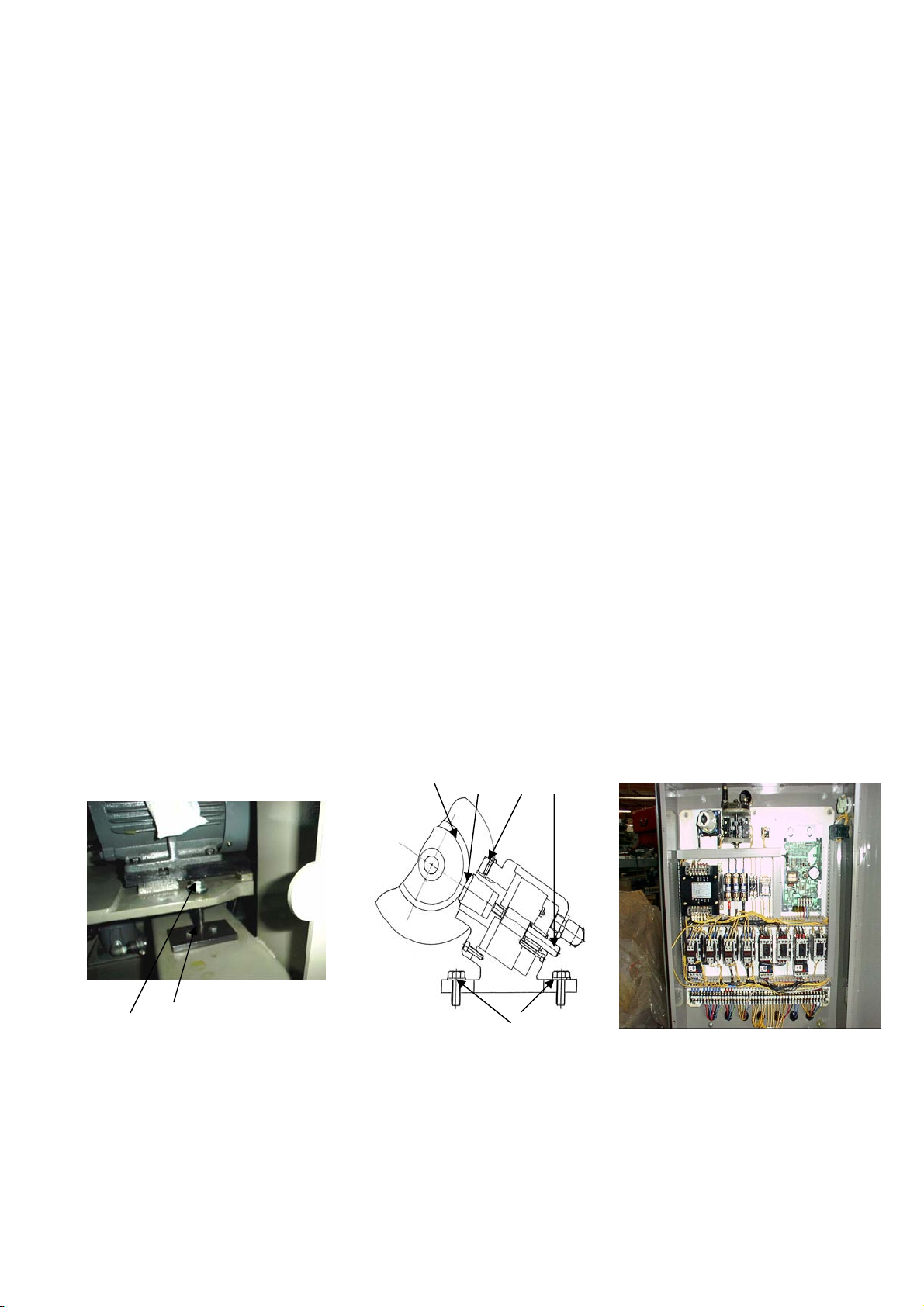
4. Leveling: Fig. 2
After the lathe is placed on its foundation it must be properly leveled. There are six
adjustable feet located under the corners of the pedestal base.
a. Place one pad under each of the feet
b. Loosen the setscrew “A” and use a pinwrench to raise or lower each foot as
appropriate for leveling.
c. Be sure all feet resting firmly on the pads.
d. When leveling is completed, tighten setscrews “A” and recheck the lathe to be
sure it is still level.
Figure 1 Lifting Machine
Figure 1 Lifting Machine
Figure 2 foundation
3
Page 6
A
C
5. INSPECTION:
When you take delivery of the lathe, be sure to check for any possible damage caused
by shock or vibration during tr a nsportation. Also check to be sure tha t all pa rts, tools
and accessories are with the lathe.
6. LUBRICATION:
Once the lathe is in place, leveled and ready for use, proper lubrication is critica l.
Please follow the recommended daily, weekly and monthly lu brication instructions.
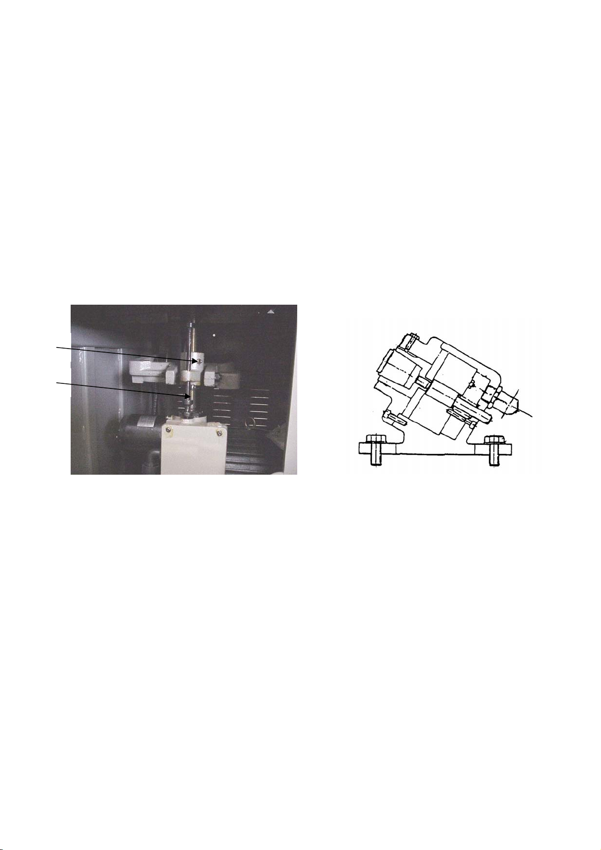
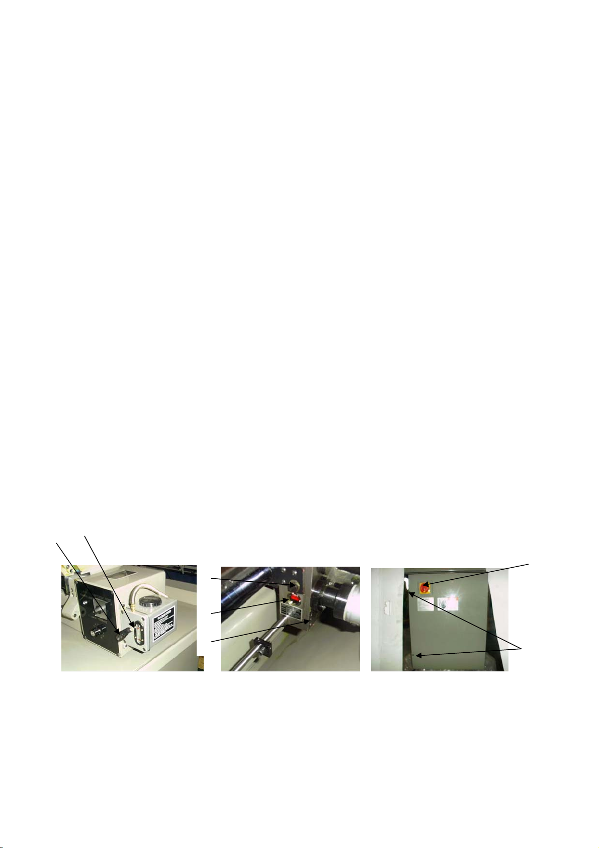
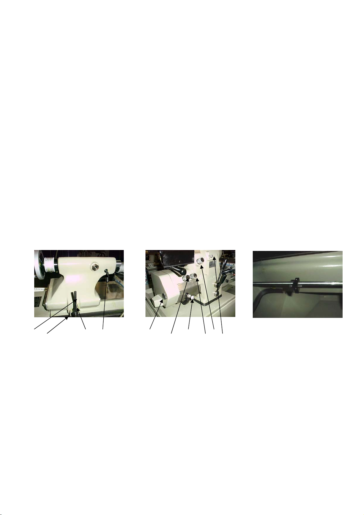
a. Vertical Screw:
Lubricate the vertical screw “C” via grease fitting “A” (Fig. 4) monthly or as
needed. Add a few drops of light oil in the vertical screw “C” (Fig.4) and the
brake cor k “B” (Fig. 5).
Figure 4 Vertical Screw Figure 5 Brake Assembly
4
Page 7
Q
b. Carriage Lubrication:
Fill the reservoir with Mobil Vactra Oil No. 2 or its equivalent. Maintain oil level
in sight window “P” (Fig) 6.
c. Gear Box and Clutch Lubrication:
Maintain oil level in sight window “S ” (F ig. 7). Carriage gearbox can be filled
by removing plug “R” (Fig. 7). Use automatic transmission fluid Mobil 20 0
(Esso ATF or its equivalent). Oil should be changed every 400 hrs. The oil drain
Plug “T” is located under the carriage gearbox (Fig. 7).
CAUTION: Use of any other type of oil in t he ge a r b ox may result in damage to the
Clutch surfaces.
d. Headstock Lubrication:
To absorb the radial and axial forces, the headstock spindle has precision
Preloaded angular contact ball bearings. These bearings a re packed with grease
for the life of the bearing a nd require no further lubrication.
7. ELECTRICAL CONNECT IONS;
The 1118H is shipped completely wired. To connect the power, do the following:
a. Turn the main switch “A” (Fig. 8) to “off” or “O”.
b. Check the voltage required which is indicated on the label at the rear of the
electrical panel.
c. Loosen screws “B” (Fig.8) to gain access to the electrical connections.
d. Connect the power source to the terminals identified as, R.S.T. and the ground
“G” in the electrical p anel (Fig. 9).
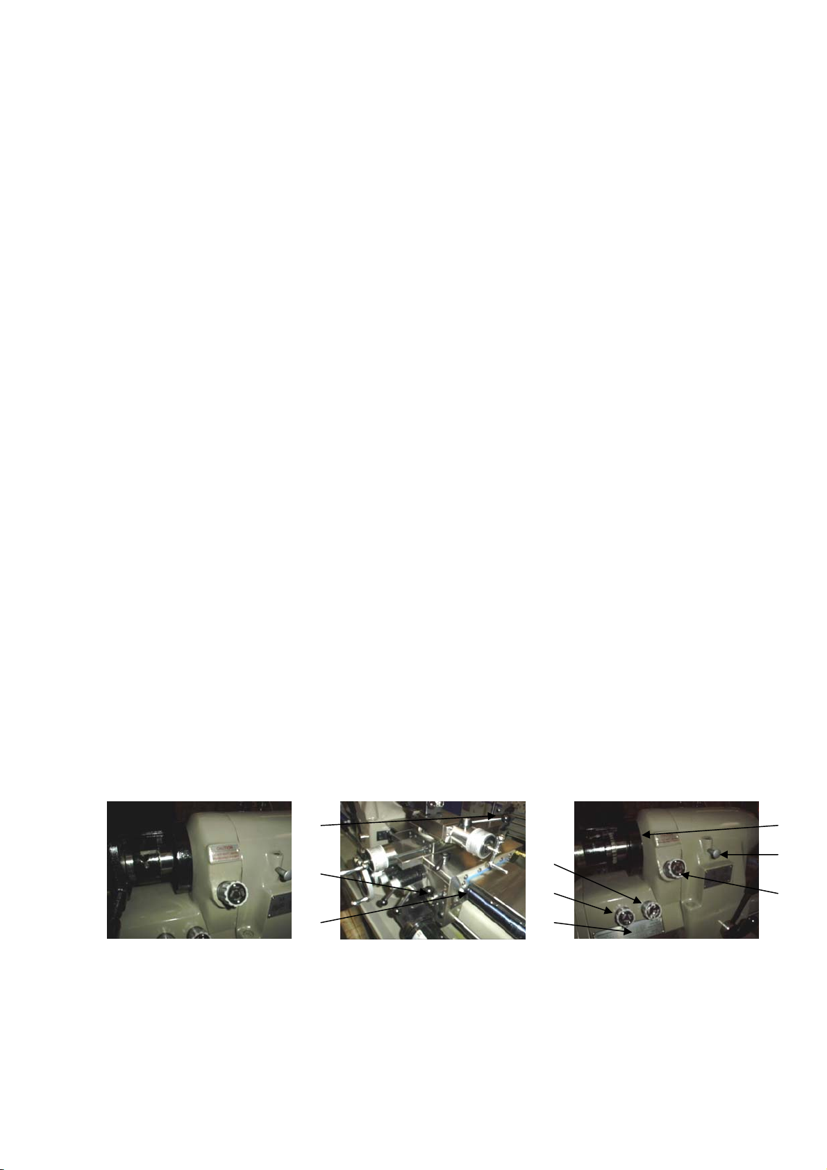
e. To check for proper rotation, place control lever “H” (Fig. 11) to the “LOW”
position, pull out spindle locking pin “E” (Fig. 11) and turn “C” (Fig.10) to the
forward position. The spindle rota tion is counter clockwise when view e d from the
supply and interchange any two leads of the R.S.T. connections and re-connect
the power. The rotation should now be correct.
CAUTION: Running the lathe in the wrong direction will result in damage to the
P
spindle speed change unit.
R
A
S
T
B
Figure 6 Carriage Figure. 7 Gearbox & Clutch Figure. 8 Electrical
Lubrication Lubrication Panel
5
Page 8
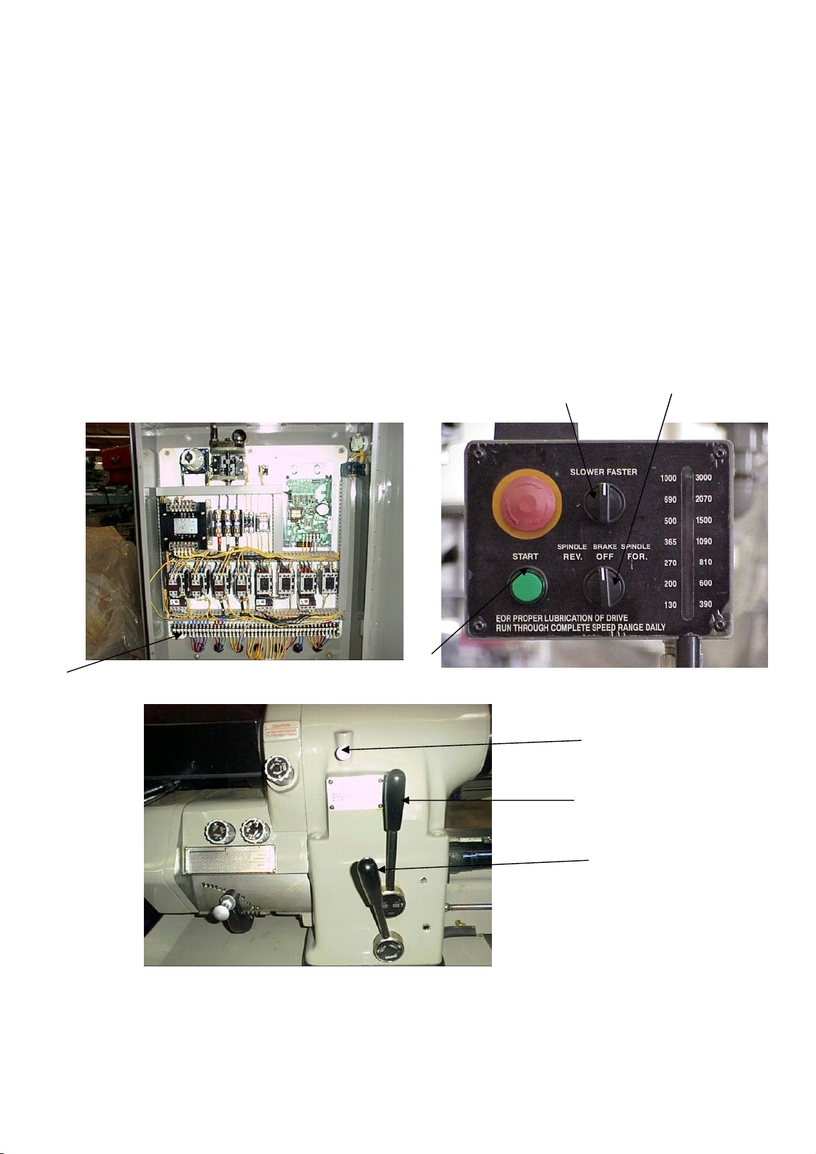
8. SPINDLE CONTROL LEVERS:
The 1118H has a high and low speed range, that is activated by moving lever “H”
(Fig. 11) to the high or low posit ion. To change speeds move lever “H” to high or low,
push the start button “B” (Fig. 10) and turn knob “C” (Fig. 10) to the forward or
reverse position. You can now change the speed by moving knob “D” (Fig. 10) to the
right to increase speed or left to reduce speed. The speed is indicated on the sight
window.
9. FREE SPINDLE
To free up the spindle so it can be turned by hand, move lever “H” (Fig.11) to the
stop position, turn knob “C” (Fig. 10) to the brake off position. At this point the spindle
will rotate by hand. To have the spindle rotate more freely you can run the machine
momentarily at 1200 RPM.
D C
R,S,T
B
Figure 9 Electrical Panel Figure 10 Spindle Speed
Indicator
E
F
H
Figure 11 Spindle Speed Control Levers
6
Page 9
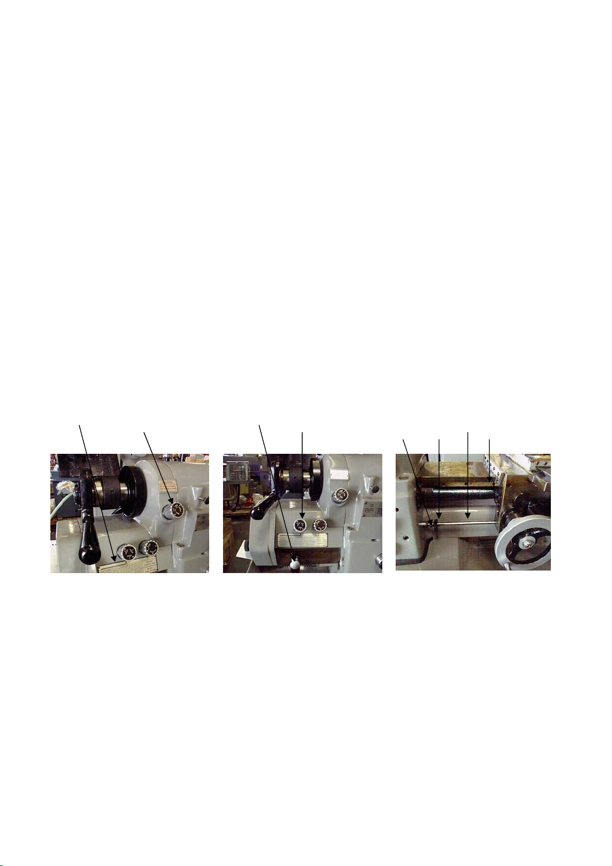
10. QUICK CHANGE GEAR BOX:
K
For conventional machining feed rate knob “I” (Fig.12) is turned to the right and to
the left for threading. Settings for threading and feed rates are located on chart “J”
(Fig.) 12. When selecting feed rate or TPI gear change arm “K” and speed change
knob “L” (Fig. 13) must be moved to the proper settings for the desired feed rate or
thread. Threads up to 250 TPI are available though the gear box ant the use of the
outside change gears. (5 change gear assembly).
CAUTION: DO NOT SHIFT GEARS WHEN THE LATHE IS RUNNING.
11. AUTO THREAD LENGTH CONTROL:
Left and right hand threads are controlled by lever “F” (Fig. 11). This lever is
connected to the control bar “M” (Fig. 14). When the carriage contacts the adjusting
screw "O” (Fig. 14) it will move the control lev er “F” (Fig.11) to the stop position.
This function when used in conjunction with the QUICK ACTING TOOL POST
COOMPOUND SLIDE ASSEMBLY described on page 11 will allow threading into
a blind hole or against a shoulder without a thread relief.
J I
L
O M P N
Figure 12 Quick Change Figure 13 Quick Change Figure 14 Thread
Gear Box I Gear Box II Length Control
7
Page 10
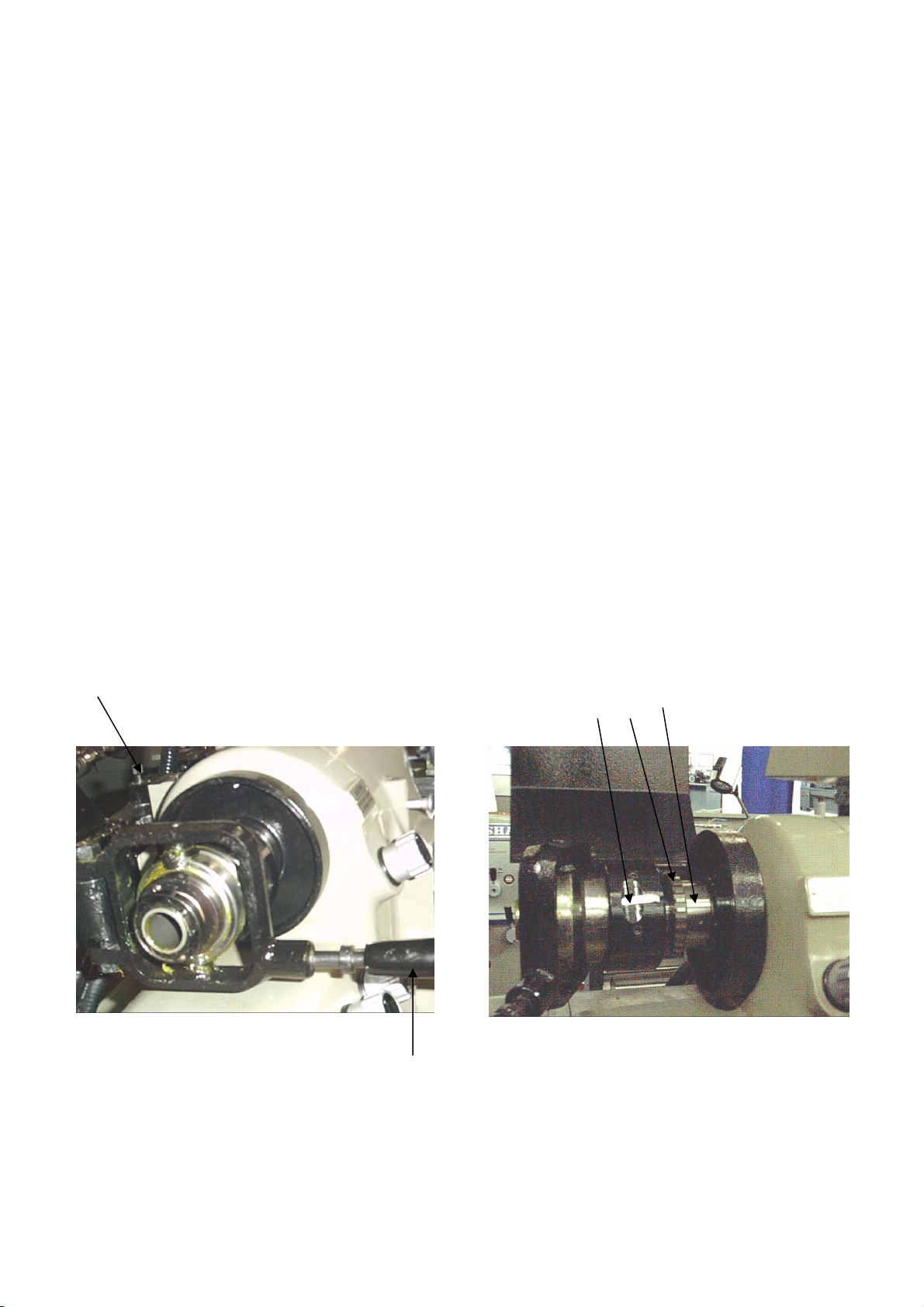
12. SPINDLE BRAKE:
The brake has been designed to stop the spindle quickly when lever “H” (Fig. 11) is
in the “BRAKE” position. The brake is actuated when the brake cork “B” (Fig. 16) is
forced against the brake drum (Fig.16) by spring tension and is release by a solenoid.
NOTE: TO PROLONG THE LIFE OF THE BRAKE, A FEW DROPS OF
SPINDLE OIL SHOULD BE APPLIED TO THE BRAKE CORK.
13. BRAKE ADJUSTMENT:
1. Loosen hex nut and setscrew “E” (Fig. 16).
2. Run the spindle at 1500 RPM.
3. While the lathe is running, turn the adjusting screw “A” on the brake solenoid
(Fig. 16) clockwise until the brake cork contacts the drum.
4. Then turn counter clockwise until the noise disappears. The brake is now
properly adjusted. (At 1500 RPM the brake should stop the spindle in
approximately 3 seconds).
NOTE: THE CLEARANCE BETWEEN THE BRAKE CORK AND THE DRUM IS
O.25mm TO 0.33mm.
14. BRAKE REPLACEMENT:
1. Disconnect wires 25 and 26 (Fig. 17) from the terminal strip and remove conduit
(C) (Fig. 15).
2. Remove bolts “S” (Fig. 16) and remove brake unit.
3. Loosen hex nut and setscrew “E” (Fig. 16).
4. Remove adjusting screw “A” (Fig. 16). Using a pin punch through the adjusting
hole remove brake cork.
5. Reverse above procedure for re-assembly.
D E B A
N F
S
Figure 15 Brake assembly Figure 16 Brake Adjustment Figure 17 Electrical
& Belt Adjustment Panel
15. BELT ADJUSTMENT:
8
Page 11
1. Run spindle at approximately 1200 RPM.
2. Move switch “C” (Fig. 10) to the “STOP” position and let the spindle coast to a
stop. (This is done to equalize the belt tension).
3. Move lever “H” (Fig.11) to the “HIGH” or “LOW”.
4. Loosen lock nut “N” (Fig. 15) and adjust w ith adjusting screw “F” (Fig. 15).
(Clockwise tightens the belts).
5. Stop the lathe and check the belt tension. (There should be approxim a tely 1” of
play in the belts. If tension is satisfactory re-tighten lock nut “N” (Fig. 15).
16. COLLET CLOSER REMOVAL:
To avoid damage to the collet closer when using chucks, face pate s or other nose
type fixtures the unit should be removed from the machine. The unit should also be
removed periodically for clea nin g to prevent the loading of chips be twe en the collet
tube, the inside of the spindle and the collet threads.
To remove the collet closer:
1. Remove pin “P” (Fig. 18). (Pin is finger tight and no tool is required).
2. Slide unit straight out of the back of the sp indle. Do not turn the adjusting nut
“Q” (Fig. 19) or any other screws. They are set at the factory.
17. REPLACING THE COLLET CLOSER:
1. Make sure the inside of the headstock spindle and outside diameter at the rear of
the spindle is clean.
2. Apply a film of light oil on the inside of adjustin g nut “Q” (Fig. 19).
3. Clean collet tube inside and out, a p pl y a film of light oil and slide into the end of
the spindle. Do not force it.
P
4. Replace pin “P” (Fig. 18).
L Q R
Figure 18 Collet Closer Figure 19 Collet Closer
A
9
Page 12
18. COLLET CLOSER ADJUSTMENT:
1. Clean inside of spindle nose and the collet.
2. Push in lock pin “E” (Fig. 11). (To engage lock pin, turn spindle until pin lines up
with the notch.
3. Disengage Adjusting Finger “L” (Fig. 19).
4. Place collet in the tube making sure the slot in the collet lines up with the pin in
the spindle.
5. Apply light pressure to collet while turn ing Shell Guard “U” (Fig. 18) making
sure the threads engage. Do not use force. If the collet does not go in smoothly,
check for burs or damaged threads.
6. Insert workpiece in the collet, move lev er “A” (Fig. 18) to the left or closed
position and turn shell guard “U” (Fig. 18) toward the operator until the collet
seats.
7. Move lever “A” (Fig. 18) to the right or release d p os i tion and turn shell guard
“U” (Fig. 18) two notches toward the operato r o n the a dj us ting finger “L”.
8. Move lever “A” (Fig. 18) to the left or closed position and test the workpiece for
correct tightness, if not correct, make any adjustments needed and lock the
adjusting finger “L”.
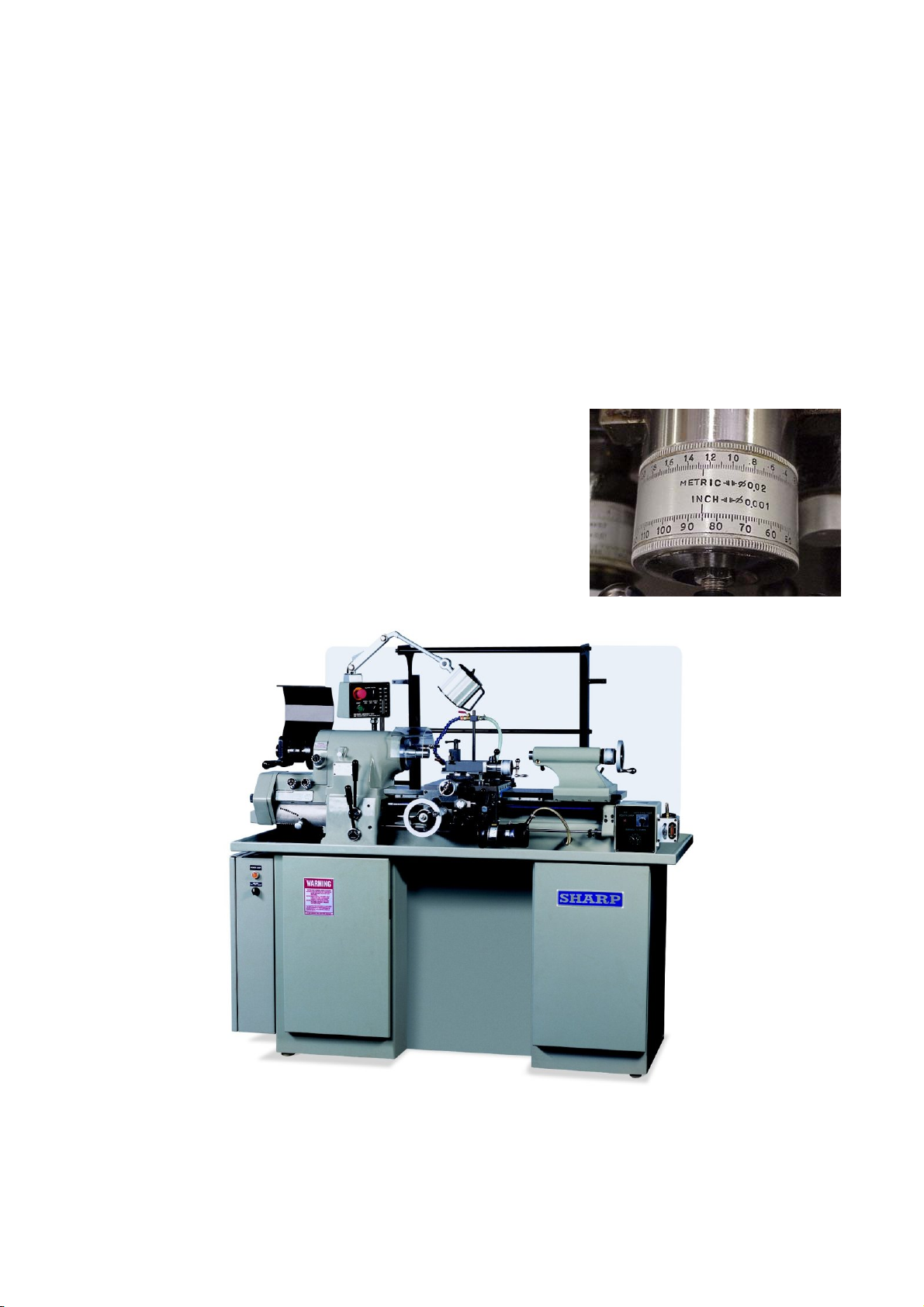
19. CARRIAGE INDICATING RING:
For convenience the handwheel dial “D” (Fig. 20) is graduated in both inch and
metric increments. (Increments are .001” and 0.02mm. The dial is spring loaded to
simplify moving to a desired position.
20. CARRIAGE LOCK:
To lock the carriage, turn handle “H” (fig. 20) clockwise, (Toward the operator) to
unlock turn counter clockwise (Away from the operator).
21. CARRIAGE CLUTCHES:
To prevent damage to the machine the carriage clutches are designed to slip when
the slide or carriage comes in contact with a feed stop. The clutches are a spring loaded arrangement and made of a friction type material. The clutches are set for
maximum torque and are not adjustable. Slippage during machining is usually an
indication of a dull tool, improper or excessive feed rate.
B
D
R
Figure 20 Carriage Figure 21 Carriage
H
10
Page 13
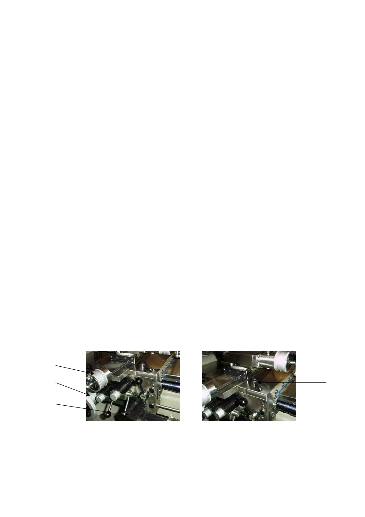
22. CROSS SLIDE INDICATING RING:
For convenience the indicating ring “B” (Fig. 20) on t he cr oss slide is graduated in
both inch and metric increments. (Increments are .001” and 0.02mm). The dial is
spring loaded to simplify moving to a desired location. Type ad operation of the
clutches are the same as the carriage. To use the taper attachment (if installed) nut
“N” (Fig. 22) must be loosened.
23 QUICK ACTION TOOL POST COMPOUND SLIDE ASSEMBLY:
The compound is equipped with a quick action slide assembly, when used in
conjunction with the auto thread le n gth control described on page 7 will allow cut ting
threads into a blind hole or against a shoulder. Handle “K” (Fig. 23) is used to operate
the quick action slide assembly. When making a cut for threads the handle is in the
forward position and moved back toward the operator at the end of the thread. Feed
for the thread depth is similar to a convention al lathe. The compound dial “J” (Fig 23)
Is graduated in .001” and 0.02mm increments and is sprin g loa de d to simplify moving
to desired location.
23. POWER FEED UNIT:
The carriage power feed unit is mounted on the carriage and is powered by a direct
current motor. (See Fig. 23).
The power feed can only be operated when the machine is running. To start t he power
feed turn cam switch “A” (Fig. 24) to the desired position. (This switch has three
positions to control the direction of travel, “STOP” “LEFT” and “RIGHT”). The feed
knob “B” (Fig. 24) controls the feed rate for both the carriage and the cross slide.
N
K
J
DC Motor
Figure 22 Compound Slide Figure 23 Compound Slide
Figure 24 Power Feed Unit
11
Page 14
The feed rate should be pre-selected to suit each particular job depending on the type
of material being machined, diameter of material, type of cut and tooling being used.
Note: The numbers on the feed control do not represent thousandths per revolution
or inches per minute. It is recommended tha t test cuts be taken to determ ine the
proper feed rate and RPM for a particular job and the results recorded for future
reference.
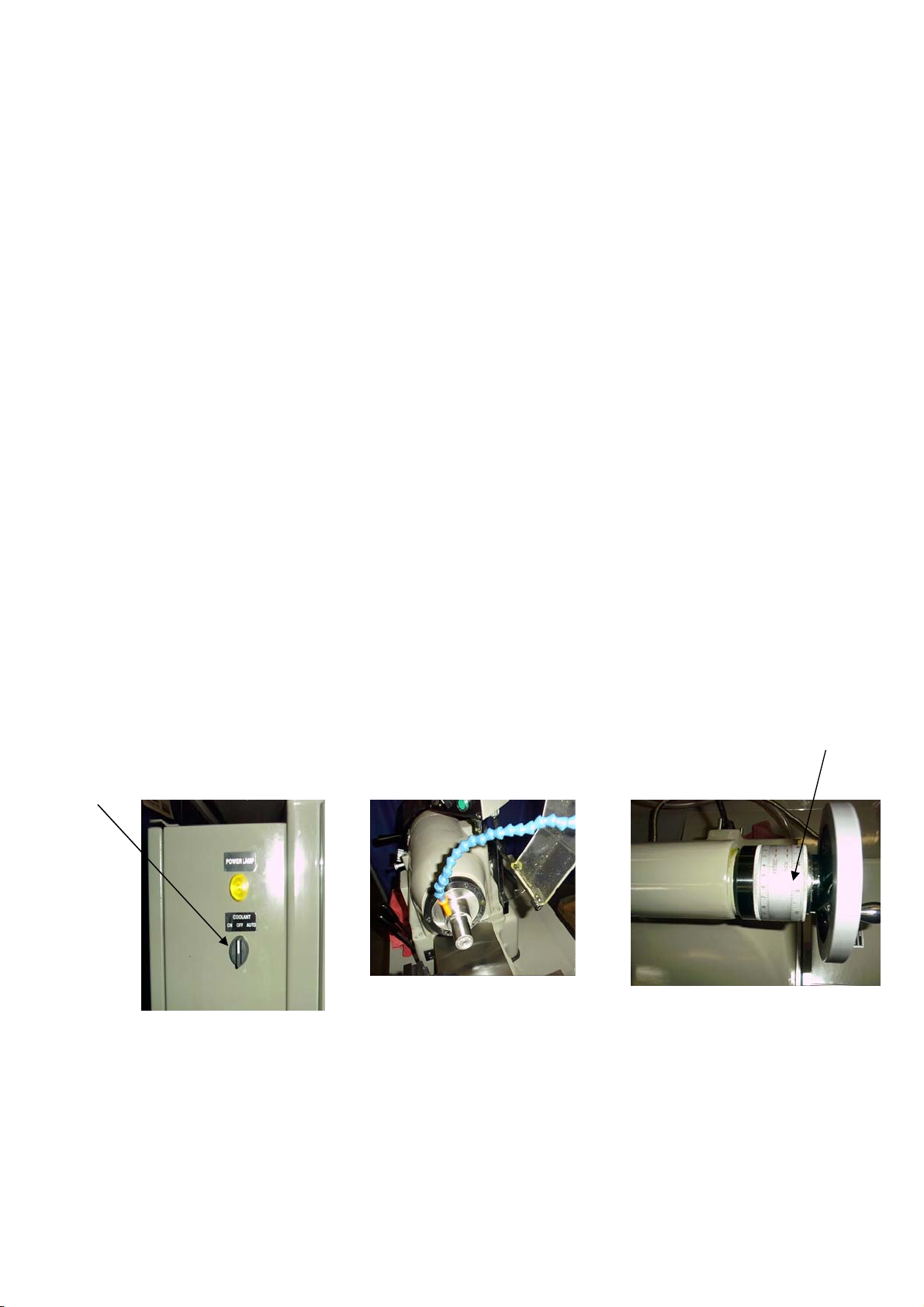
25: COOLANT:
The coolant pump is controlled by Switch “C” (Fig. 25) and has three positions,
“ON” “OFF” and “AUTO” When in the on position the coolant is consta nt an d it th e
“AUTO” position the coolant is only on when the machine is running. The sump
should be cleaned on a regular basis.
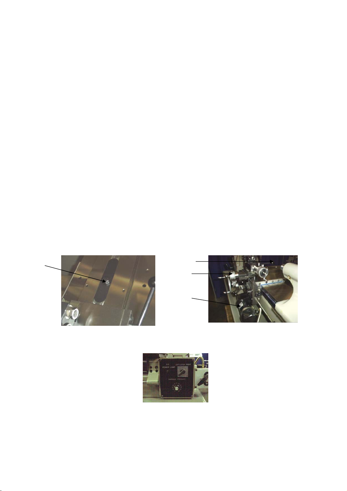
26. TAILSTOCK ASSEMBLY:
Pre-loaded ball bearings have be e n i ns ta lle d t o support the load between the tai l stoc k
and the spindle. The tailstock spindle is graduated in both inches and metric. (1/8”
and 1mm increments). The total travel is 3 ¾” or 92.25mm. The dial ring “D”
(Fig.27) is spring loaded and graduated in both inch and metric. (0.001” and 0.02mm
increments).
27. TAILSTOCK SPINDLE LOCK:
To lock the tailstock spindle move lever “H” (Fig.28) toward the spindle and awa y
from the spindle to unlock.
C
28. TAILSTOCK LOCK:
The tailstock can be locked in place using lever “E” (Fig. 28). Lever “E” should be
adjusted between clamp stops “F” and “G” (Fig. 28) so that when fully clamped it
does not touch stop pin “F”.
Figure 25 Coolant switch Figure 26 Coolant Nozzle Figure 27 Tailstock Dial
D
12
Page 15
THREADING
CAUTION: DO NOT RUN THE SPINDLE IN REVERSE WHEN THREADING.
The Tool Room Lathe is designed to cut threads quickly and accurately. The quickchange gearbox permits instant selec tio n of up to 36 different English and Metric threads.
Threads can be cut to a shoulder by setting the automatic stop to a predetermined point in
either direction. Before cutting a thread, select the proper cutting speed for the size of the
thread and material to obtain the desired finish. MAXIMUM RECOOMMENDED
THREADING SPEED IS 1000 RPM.
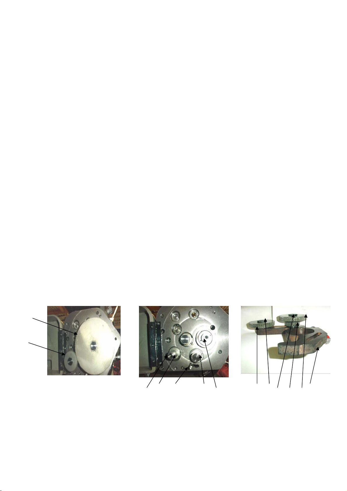
To set the quick-change gearbox for a desired pitch, pull the spring loaded knob “A” (Fig.
29) out as far ass it will go and lower it until can be moved sideways to the desired notch
directly under the thread required. Raise the handle so the plunger can drop into the hole.
If the handle cannot be raised far enough for the plunger to drop into the hole, loosen
knob “F” (Fig.29), open the gearbox d oor and rotate gear “B” (Fig. 34) until the gears
mesh allowing the handle to be raised.
Set ENGLISH / METRIC knob “B” (Fi g. 29) so thread system to be cut is at t he top, if it
does no engage loosen knob “F” (Fig. 29) open gearbox door and rotate gear “B” (Fig.34)
until it engages. To engage gearbox turn knob “D” (Fig. 29) to the treading position. If
the sliding gear in the gearbox does n ot mesh with the headstock spindle gear it m ay be
necessary to turn the headst oc k s pindle by hand using the handwheel “ P ” (Fig. 31) until a
definite click is heard.
E G F H F C A B D E
Figure 28 Figure 29 Figure 30
Tailstock body & Headstock & gearbox Thread
Spindle Lock Length control
13
Page 16
Set compound at 61º and position cutting tool in compound slide tool post. Position the
carriage so the tool is in the center of the part to be threaded.
Lever “F” (Fig. 11) is used to control direction of feed. When moved to the left carriage
travel is to the left, when moved to the right travel is to the right and when in the center
position the carriage is stoped.
NOTE: CARRIAGE POWER FEED UNIT IS NO USED FOR THE THREADING
OPERATION.
Place lever “F” (Fig.11) in the center position and engage lead screw nut “Q” (Fig.32) by
moving lever “R” (Fig. 32) clockwise. Set the two carriage stops “I” (Fig. 30) by
loosening set screw “H” (Fig.30) to appr ox imate thread length and re-tighten set screw
“H”. Final adjustment of the stops can be m ade with adjusting screw “G” (Fig. 30). Make
a trial run with th e tool away from the work to pick up the shou lder or end of the triad by
using the tool post slide. The tool should clear the right side of the thread by
approximately 6.5nn.
NOTE: LOCK CARRIAGE STOPS SECURELY BEFORE STARTING THE
THREADING OPERATION. DO NOT RELEASE CARRI AGE NUT “ Q” (Fig.32)
UNTIL THE THREADING OPERATION IS COMPLETED.
Once the stops are set, move the carriage to the right using lever “F” (Fig.11) and adjust
the tool by use of the cross-feed.
Left hand threading can be done wit h the spin d le running in the “FORWARD” direct io n,
except the threading will be done from left to right.
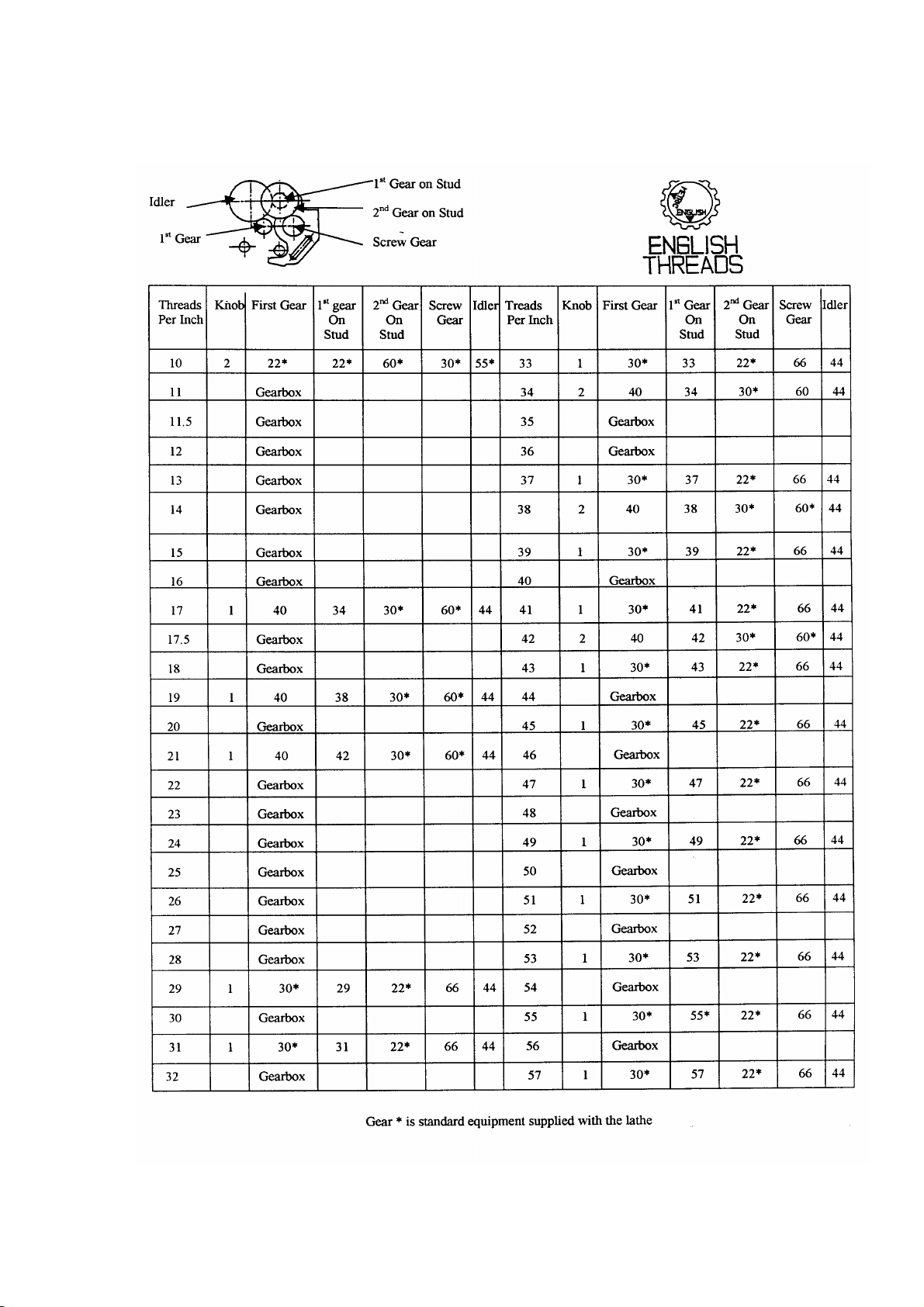
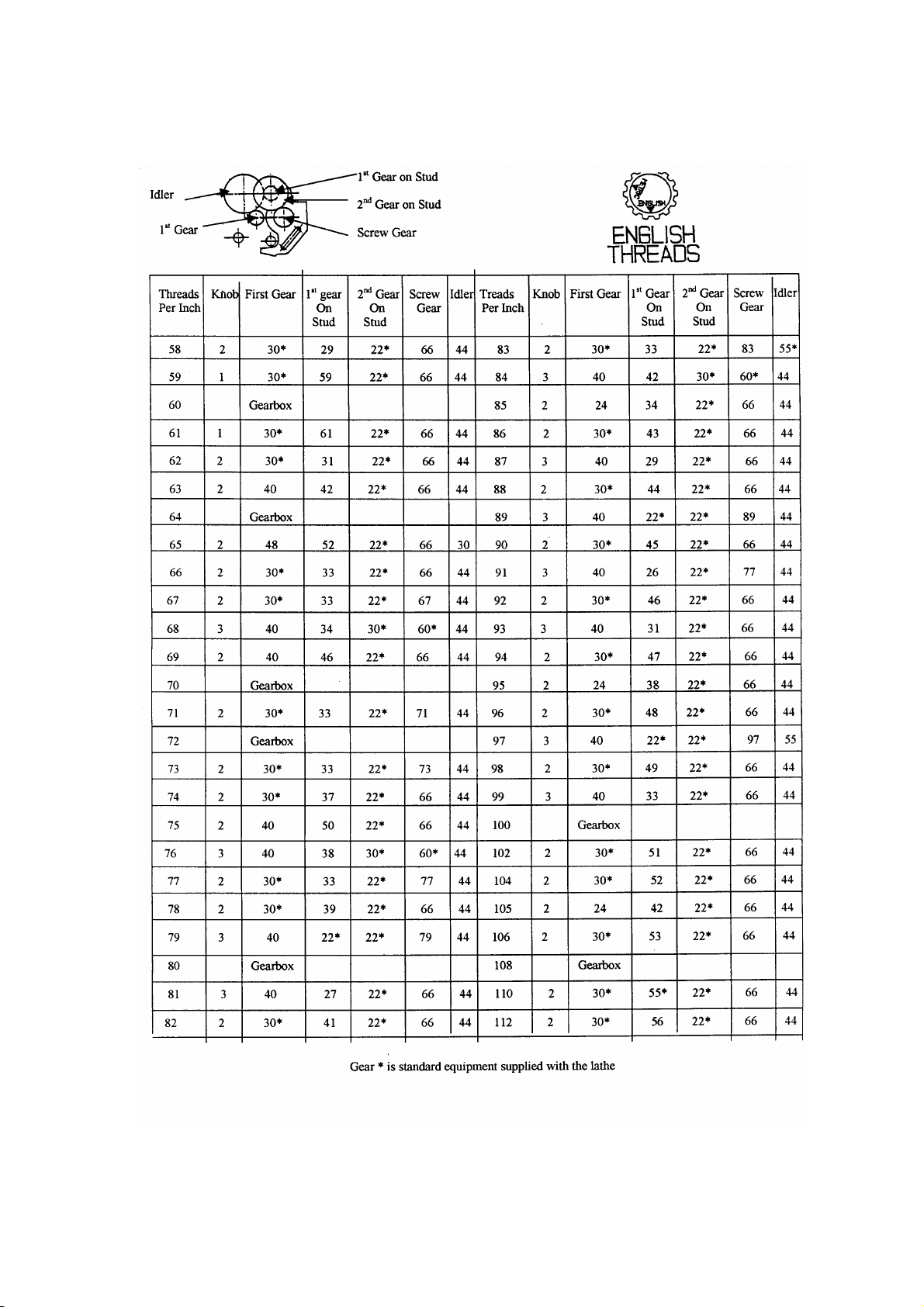
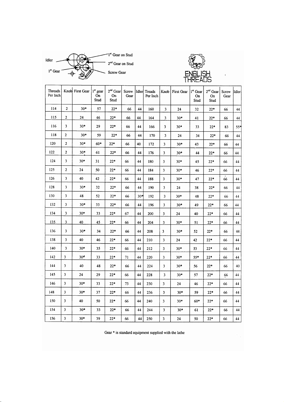
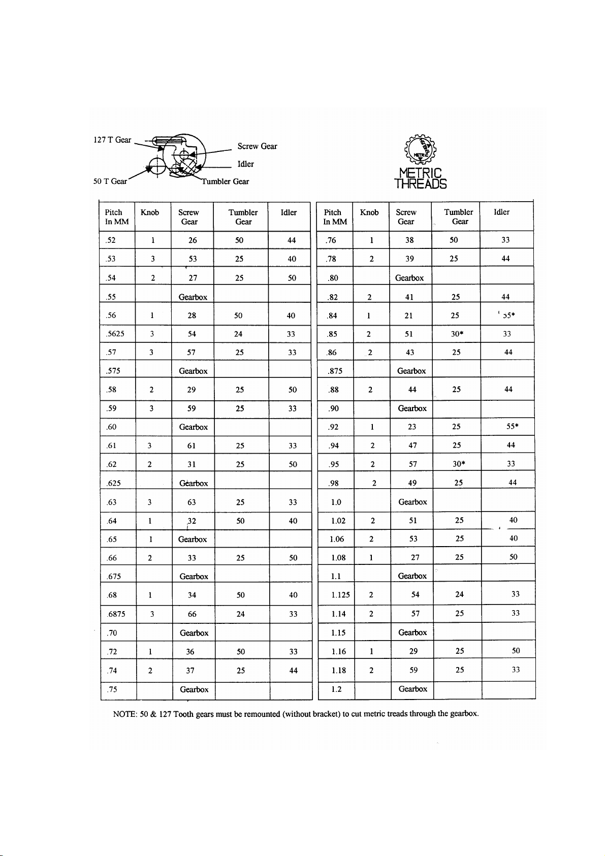
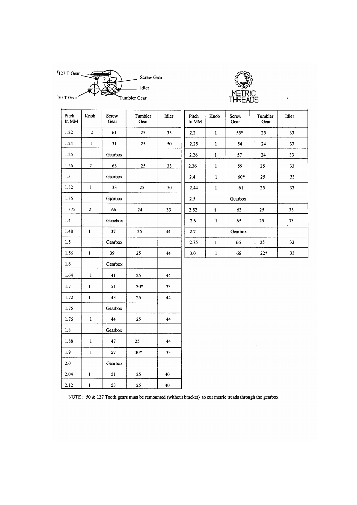
OUTSIDE CHANGE GEARS
A set of five gears and bracket are pr o vid ed as standard equipment for cutting threads not
available in the quick-change gearbox. When set up per the chart on page 18, 10 threads
per inch or 0.25mm pitch can be cut. Three gears are shipped on the bracket and the other
two are in place of the shafts as shown at positions “O” and “F” (Fig.35).
NOTE: BEFORE SETTING UP CHANGE GEARS, PLACE KNOB “A” (Fig.29) IN
THE “OUT” POSITION.
S
R
Q
B
C
L
Figure 31 Spindle Figure 32 Carriage Figure 33 Gearbox
Handwheel
P
E
D
14
Page 17
A
B
The tumbler handle bracket within the gear box has a round safety bar “ D” (Fig.35) to
prevent installing change gears out side of the gear box until the tumbler handle “A”
(Fig.29) is in the out position. (Additional gears are availabl e for cutting threads not
available through the gearbox).
Be sure to lubricate bushings and shafts on the change gear bracke t with spind l e oil each
time a set up is made. If long run threa ding is involved, lubricate daily.
ENGLISH THREADS USING OUTSIDE CHANGE GEARS
1. Turn off power supply.
2. On the english side of the change gea r brac k et “L” (Fig.36) mount first gear on stud
“K” with spacer between gea rs . O nly snug bolt “I” (Fig.36).
3. Mount Idler Gear “G” and snug bolt “H”, but do not mesh with first gear on stud “K”.
4. Loosen knob “F”(Fig.29), open gearbox door and remove 50-tooth gear “A” and 127-
tooth gear “B”(Fig.34).
5. If the thread chart specifies the number of teeth in the first gear to be other than 22
teeth gear “C” (Fig.35) must be replaced with specified gear.
6. Remove tumbler gear “F” (Fig.35).
7. Moount change gear bracket assembly (Fig.36 on pivot post “E” (Fig.35) and snug
bracket bolt “R” (Fig.37).
8. Make certain key is in place and mount screw gear “ H” (Fig. 3 7) and replace bolts
“U” and “V”.
9. Adjust gear on stud “P” (Fig.37) with gear “H” allowing .003 to .004” backlash and
tighten bolt “Q” (Fig.37).
10. Adjust gear “M” allowing .003” to .004” between it and gear “O” (Fig.35) and tighten
bolt “N” (Fig.37).
11. Pivot bracket to obtain .003” to .004” backlash between gear “O” (Fig35) and gear
“M” (Fig. 37) and tighten bolt “ R” (F ig.37).
12. Check all gears f or proper fit and all bolts are properly tightened.
13. Close gearbox door, tighten knob “F” (Fig.29) and set knob “C” (Fig.29) to the
position specified on the chart.
14. Turn English/Metric knob “B” (Fig.29) to “English”.
O C D F E
G H I K J L
Figure 34 Threading Figure 35 Threading Figure 36 Change
Gear Gearbox Gear Bracket
15
Page 18

15. Set Feed/Thread knob “D” (Fig.33) to the Thread position.
16. Follow the same procedures for setting carriage stops, lead screw nut and compound
slide as when cutting threads from the gear box.
NOTE:
a. the 50 tooth gear “A” and 127 tooth gear “B” (Fig.34) must be remounted
(without the bracket) to cut metric threads through the gearbox.
b. When disassembling setup, remount 22 tooth gear “O” and gear “F” (Fig.35).
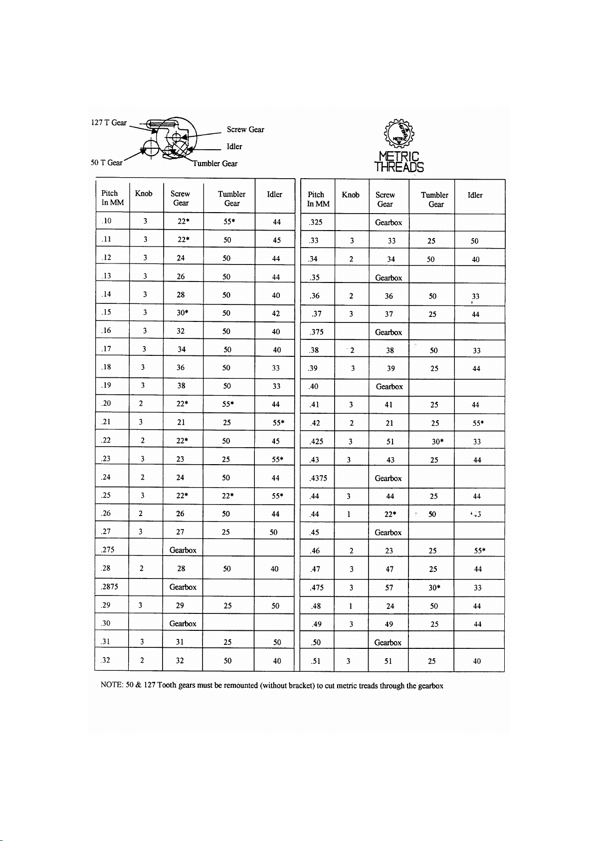
METRIC THREADS USING OUTSIDE C HA NGE GEARS
1. Turn off power supply.
2. Mount Idler Gear “Y” on the metric side of the change bracket “X” (Fig.38) and snug
bolt “B”.
3. Loosen knob “F” (Fig.29), open gearbox door and remove 127-tooth gear “B” (Fig34).
4. Mount change gear bracket assembly (Fig.38) on pivot post “E” (Fig.35) and snug
Bolt “B” (Fig.39).
5. Remove First Gear “O” (Fig.35) and replace bolt. (Do not misplace key).
6. Mount First Gear on screw “D” (Fig.39).
7. If the thread chart specifies the number of teeth for the Tumbler Gear to be other than
22 teeth, replace gear “F” (Fig.35) with the specified gear.
8. Adjust Idler Gear “G” (Fig.3 9 ) allowing .003” to .004” backlash between it and
tumbler gear “F” and tighten bolt “E” (Fig.39).
9. Pivot bracket to obtain .003’ TO .004” backlash between the idler gear “G” and
tumbler gear “F”. Tighten bracket bolt “B” (Fig.39).
10. Be certain key is in pl ac e and remount 127 tooth bear. Tighte n B olt “ Q” (Fig.37).
11. Re-check gears for proper backlash and all bolts for tightness.
12. Close gearbox door, tighten knob “F” (Fig.29) and turn change knob “C” (Fig.29) to
position specified on the chart.
13. Turn English / Metric knob “B” (Fig.29) to “Metric”.
14. Turn Feed / Thread knob “E” (Fig.29) to “Thread”.
15. Follow the same the same procedures for setting carriage stops, lead screw nut and
compound slide as previously described.
16. Observe the same operational precautions as when cutting threads from the gearbox.
16
Page 19
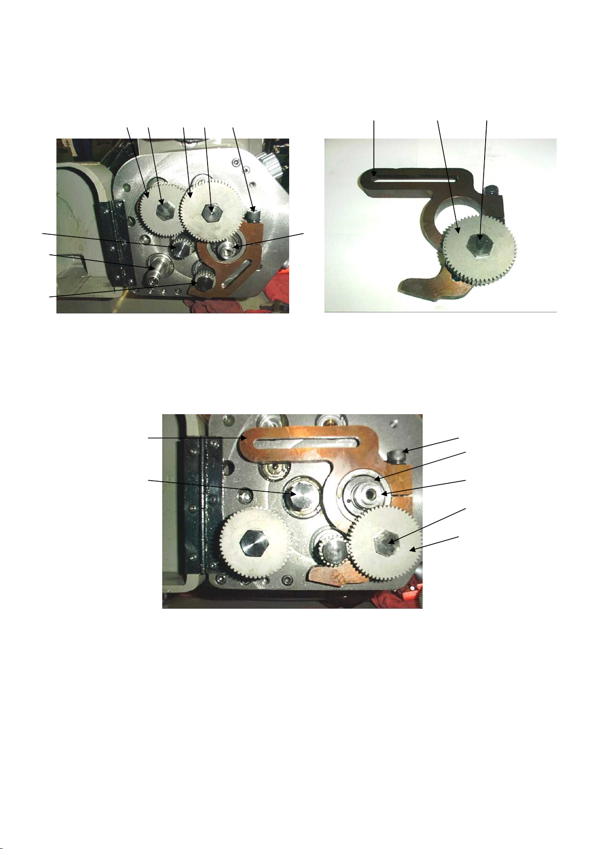
S
U
V
M N P Q R
X Y Z
H
Figure 37 Mounting Change Gear Bracket Figure 38 Change Gear Bracket
A
C
B
E
D
F
G
Figure 39 Mounting Change Gear Bracket
17
Page 20
18
Page 21
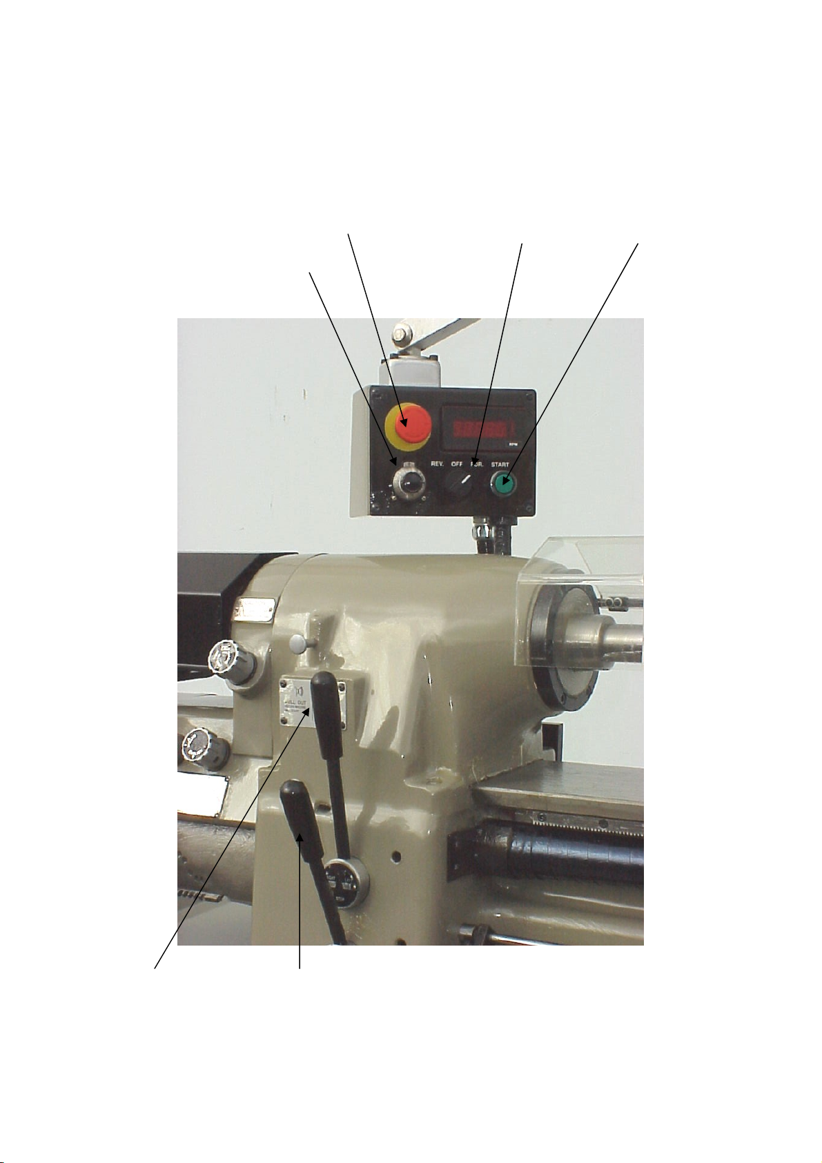
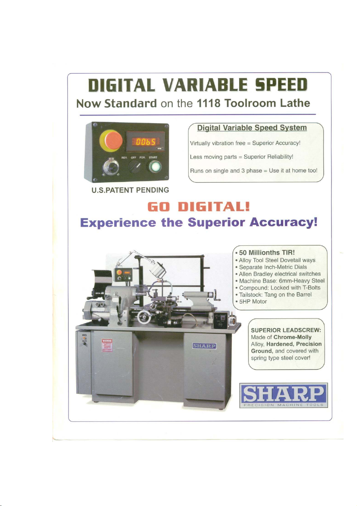
1118H CONTROL WITH DVS
Emergency Stop FWD/OFF/REV Power Switch
RPM Indicator
Threading Lever Spindle LOW/STOP/HIGH
19
Page 22
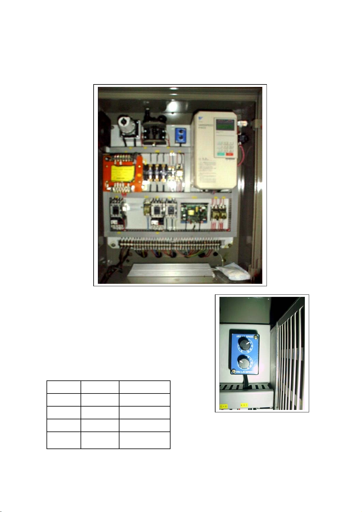
ELECTRICAL BOX with INVERTER
Upper Dial Lower Dial High/Low Ratio
7 3 3 : 1
7 5 2.5 : 1
7 6 2 : 1
7 7.5 1.5 : 1
20
Page 23
21
Page 24
22
Page 25
23
Page 26
24
Page 27
25
Page 28
26
Page 29
27
Page 30

PARTS LIST CONTENTS
Description
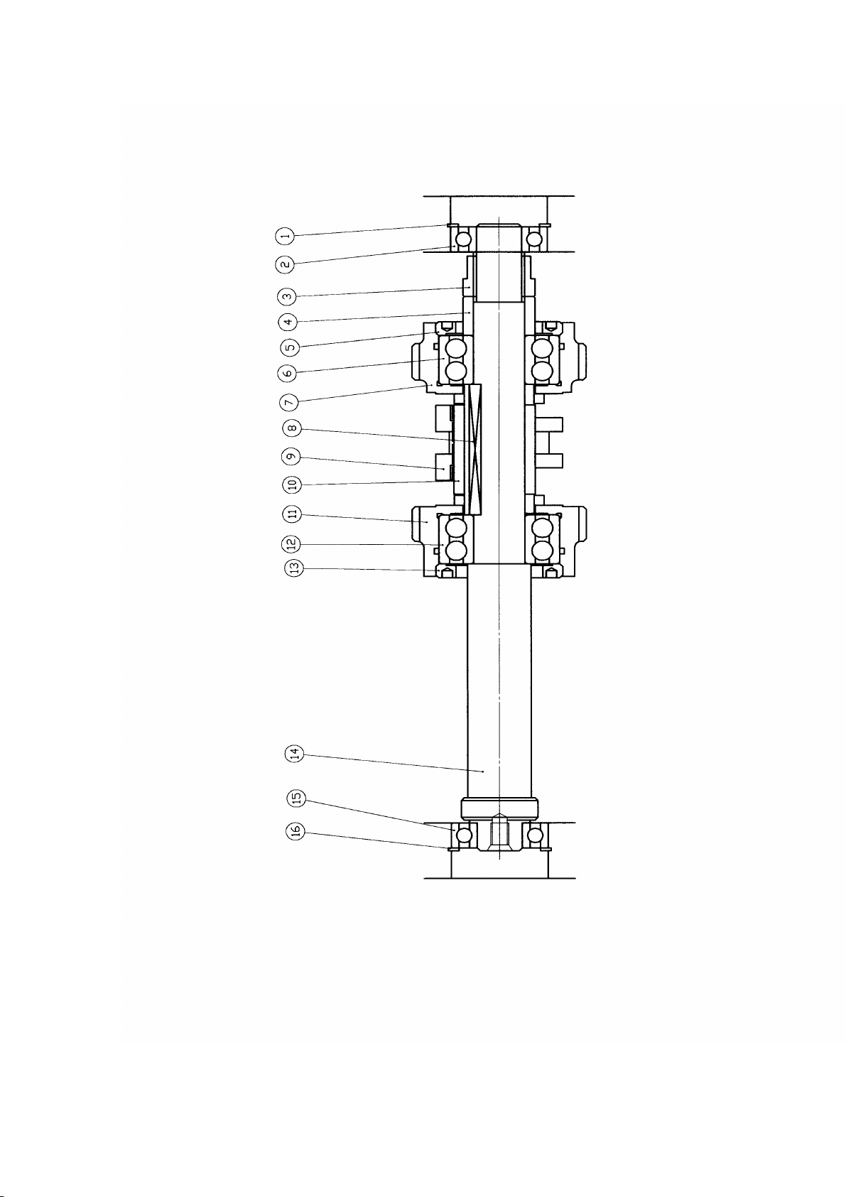
Headstock I --------------------------------------------------
Headstock II -------------------------------------------------
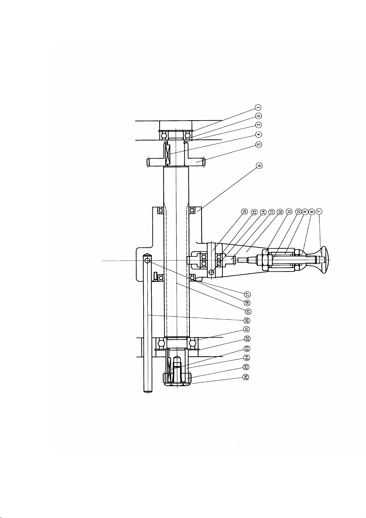
Collet closer assembly -------------------------------------
Gear box assembly I ---------------------------------------
Show which shaft assembly on gear box assembly II ---
2nd drive shaft ---------------------------------------
rd
drive shaft ---------------------------------------
3
th
4
drive shaft ---------------------------------------
5th drive shaft ---------------------------------------
6th drive shaft ---------------------------------------
7th drive shaft ---------------------------------------
th
drive shaft ---------------------------------------
8
th
9
drive shaft ---------------------------------------
Gear part( for forward & reverse thread shaft) --------
Gear change assembly ------------------------------------
Bed assembly ---------------------------------------
Cross slide & compound slide -------------------------
Carriage gear box ---------------------------------------
Feed clutch assembly --------------------------------------
Pedastal assembly (old style) -------------------------------
D.C. motor power feed control assembly ---------------
D.C. motor assembly -----------------------------------
Variable speed control box assembly(old style)----------
Brake assembly -------------------------------------
Variable speed pulley assembly(old style)-----------------
Variable speed drive control assembly(old style)---------
Tailstock assembly -----------------------------------
Motor drive system assembly(new style) ---------------
Padestal assembly(new style) ---------------------------
Control plate assembly(new style) -------------------------
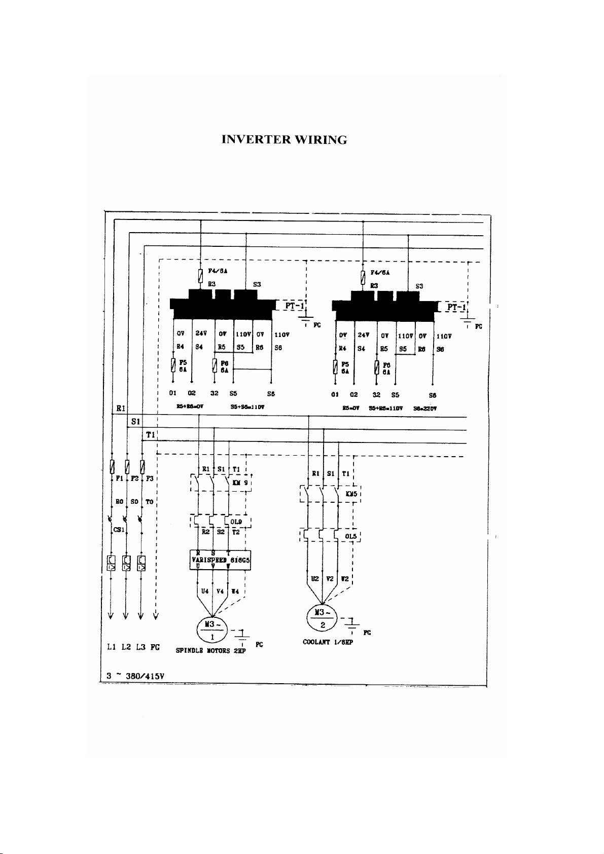
Inverter wiring view ---------------------------------------
Inverter wiring --------------------------------------
Wiring for old style -------------------------------------
Drawing page
1
3
5
7
9
10
12
14
16
18
20
22
24
26
28
30
33
37
40
42
44
46
48
50
52
54
56
59
61
63
65
66-69
70
Parts list page
2
4
6
8
11
13
15
17
19
21
23
25
27
29
31- 32
34-36
38-39
41
43
45
47
49
51
53
55
57-58
60
62
64
Page 31

HEADSTOCK
1
Page 32

W
HEADSTOCK I
KEY PART N UM B ER DESCRIPTION QUA NTITY
OOO1 GTC 11080 SPINDLE 1
OOO2 SS 06012 SET SCREW 1
OOO3 GCT 11160 KEY SCREW 1
OOO4 GCT 11050 FRONT CAP 1
OOO5 GCT 11060 G ASKET 1
OOO6 SP 03012 STRAIGHT PIN 1
OOO7 ACBB 7014CP4 BEARING 1
OOO8 GCT 11080 SPACER 1
OOO9 GCT 11090 SPACER 1
OO10 GCT 11010 HEAD STOCK 1
OO11 TP 08040 TAPER P IN 2
OO12 DRK 04045 KEY 1
OO13 GCT 11020 PULLEY 1
OO14 11M-11700 BELT 2
OO15 GCT 11030 SPINDLE NUT 1
OO16 CP 05 PLUG 2
OO17 SS 06008 SET SCREW 2
OO18 GCT 11260 SPACER 1
OO19 DRK 04025 KEY 1
OO20 GCT 11210 DRIVE GEAR 1
OO21 GCT 12010 GEAR BO X 1
OO22 DRK 04014 KEY 1
OO23 GCT 11200 HAND WHEEL 1
OO24 GCT 11190 NUT 1
OO25 CP 05 PLUG 2
OO26 SS 06008 SET SCREW 2
OO27 GCT 11120 SCRE
OO28 GCT 21010 BED 1
OO29 GCT 21430 SLIDE 1
OO30 00R 5 "O" RING 1
2
6
Page 33

3
Page 34

HEADSTOCK II
KEY PART N UM B ER DESCRIPTION QUA NTITY
OOO1 EC 06 CONNECTOR 1
OOO2 SHS 10040 SCREW 3
OOO3 SS 10012 SET SCREW 2
OOO4 GCT 11110 PLUG 1
OOO5 LW 010 LOCK WASHER 4
OOO6 GCT 11230 SET SCREW 1
OOO7 SS 04012 SET SCREW 4
OOO8 GCT 11170 NAME PLATE 1
OOO9 SS 0425 SET SCREW 2
OO1O MSZ - 15 MICRO SWITCH 1
OO11 GCT 11130 SPRING 1
OO12 GCT 11140 PLUNGER 1
OO13 GCT 11150 LOCKING PIN 1
OO14 GCT 11090 SCREW 1
OO15 SSB 06012 SET SCRE W 1
4
Page 35

5
Page 36

COLLET CLOSER ASSEMBLY
KEY PART N UM B ER DESCRIPTION QUA NTITY
OOO1 TP 08040 TAPER PIN 2
OOO2 GCT 11100 COLLET CLOSER BRACKET 1
OOO3 SS 08020 SET SCREW 3
OOO4 GCT 14030 LINK PIN 1
OOO5 CRR 012 SNAP RING 2
OOO6 GCT 14230 KEY 1
OOO7 GCT 14080 ADJUSTING NUT 1
OOO8 PB 03012 PIN 1
OOO9 GCT 14220 SPRING HOUSE 1
OO1O GCT 14170 SPRING 1
OO11 GCT 14100 ADJUSTING FINGER
OO12 PB 04016 PIN 1
OO13 GCT 14150 RING 3
OO14 SHS 05012 SCREW 4
OO15 GCT 14200 LOCKING JAW 3
OO16 GCT 14060 PROTATING RING 1
OO17 GCT 14180 CLUTCH CONE 1
OO18 BB 6208ZZ BEARING 1
OO19 GCT 14190 LO C KING N U T 1
OO2O DR K 02B30 KEY 1
OO21 GCT 14210 STOP RING 1
OO22 GCT 14090 COLLET SPINDLE 1
OO23 GCT 14070 CONNECTING LINK 1
OO24 NF 1 2 NUT 2
OO25 GCT 14040 PIVOT SCREW 2
OO26 CRS 033 RETAINING RING 1
OO27 GCT 14120 SPRING DISC 1
OO28 GCT 14030 SCREW 1
OO29 G CT 14020 SWIVEL BLOCK 2
OO30 GCT 14010 YOKE LEVER 1
OO31 GCT 14130 LEVER 1
OO32 GCT 14110 HANDLE 1
6
1
Page 37

7
Page 38

GEAR BOX ASSEMBLY I
KEY PART N UM B ER DESCRIPTION QUA NTITY
OOO1 SHS 06025 SCREW 3
OOO2 SS 06008 SET SCREW 2
OOO3 GCT 12410 PLATE 1
OOO4 SHS 04010 SCREW 2
OOO5 TP 08040 TAPER PIN 1
OOO6 SHS 08035 SCREW 4
OOO7 TP 08035 TAPER PIN 1
OOO8 SHS 06035 SCREW 1
OOO9 HRS 04010 SCREW 6
OO10 GCT 12940 SWIVEL LINK 1
OO11 GCT 12960 COVER 1
OO12 HRS 05012 SCREW 4
OO13 HRS 05012 SCREW 4
OO14 GCT 12970 COVER 1
OO15 GCT 13010 WARNING PLATE 1
OO16 M P 02 PIN 4
OO17 GCT 12980 THREAD FEED PLATE 1
OO18 GCT 12990 CHANGE PLATE 1
OO19 GCT 13000 SELECT PLATE 1
OO20 GCT 13020 THREAD CH AR T PLA TE 1
OO21 GCT 12950 GEAR BOX 1
OO22 GCT 12940 LOCK KNOB 1
OO23 GCT 12740 KNOB 3
OO24 GCT 12720 UPPER SLEEVE 1
OO25 GCT 12730 LOWER SLEEVE 2
OO26 GCT 12750 GEAR SHAFT 3
1
8
Page 39

9
Page 40

10
Page 41

2ND DRIVE SHAFT ASSEMBLY
KEY PART N UM B ER DESCRIPTION QUA NTITY
OOO1 SHS 05012 SCREW 2
OOO2 GCT 12060 GEAR STOP BLOCK 1
OOO3 BB 6002ZZ BEARING 1
OOO4 CRR 032 RETAINING RING 1
OOO5 GCT 12040 SHAFT 1
OOO6 DRK 04020 KEY 1
OOO7 GCT 12050 LOCKING SHAFT 1
OO7A SS 10010 SET SCREW 1
OOO8 GCT 12030 GEAR 1
OOO9 BB 6001ZZ BEARING 1
OO1O CRR 032 RETAINING RING 1
11
Page 42

12
Page 43

3rd DRIVE SHAFT ASSEMBLY
KEY PART N UM B ER DESCRIPTION QUA NTITY
OOO1 CRR 032 RETAINING RING 1
OOO2 BB 6002ZZ BEARING 1
OOO3 GCT 12070 GEAR SHAFT 1
OOO4 BB 6002ZZ BEARING 1
OOO5 CRR 032 RETAINING RING 1
13
Page 44
14
Page 45

4th DRIVE SHAFT ASSEMBLY
KEY PART NUMBER DESCRIPTION QUANTITY
OOO1 CRR 032 RETAINING RING 1
OOO2 BB 6002ZZ BEARING 1
OOO3 GCT 12160 LOCKING NUT 1
OOO4 GCT 12150 SLEEVE 1
OOO5 GCT 12190 LOCKING NUT 1
OOO6 DBB 5203ZZ BEARING 1
OOO7 GCT 12130 CLUTCH GEAR 1
OOO8 DRK 04045 KEY 1
OOO9
OO1O GCT 12110 KEY SLEEVE 1
OO11 GCT 12100 CLUTCH GEAR 1
OO12 DBB 5203ZZ BEARING 1
OO13 GCT 12090 LOCKING NUT 1
OO14 GCT 12080 GEAR SHAFT 1
OO15 BB 6002ZZ BEARING 1
OO16 CRR 032 RETAINING RING 1
GCT 12120
CLUTCH
1
15
Page 46

16
Page 47

5th DRIVE SHAFT ASSEMBLY
KEY PART NUMBER DESCRIPTION QUANTITY
OOO1 CRR 032 RETAINING RING 1
OOO2 BB 6002ZZ BEARING 1
OOO3 GCT 12170 GEAR SHAFT 1
OOO4 DRK 05040 KEY 1
OOO5 GCT 12200 DRIVE GEAR 1
OOO6 SS 05010 SET SCREW 2
OOO7 GCT 12210 DRIVE GEAR 1
OOO8 BB 6002ZZ BEARING 1
OOO9 CRR 032 RETAINING RING 1
17
Page 48

18
Page 49

6th DRIVE SHAFT ASSEMBLY
KEY PART NUMBER DESCRIPTION QUANTITY
OOO1 CRR 032 RETAINING RING 1
OOO2 BB 6002ZZ BEARING 1
OOO3 GCT 12240 CONVERSION GEAR 1
OOO4 GCT 12230 CONVERSION FORK 1
OOO5 BB 6805ZZ BEARING 1
OOO6 CRR 025 RETAINING RING 1
OOO7 DRK 04185 KEY 1
OOO8 GCT 12270 CHANGE GEAR 1
OOO9 SRK 04015 KEY 1
OO1O GCT 12260 CHANGE GEAR 1
OO11 SHS 04010 SCREW 2
OO12 GCT 12250 CHANGE GEAR 1
OO13 GCT 12220 GEAR SHAFT 1
OO14 BB 6004ZZ BEARING 1
OO15 CRR 042 RETAINING RING 1
OO16 GCT 12280 SLEEVE 1
OO17 SRK 03023 KEY 1
OO18 GCT 12290 PINION 1
OO19 GCT 12300 BOLT 1
19
Page 50

20
Page 51

7th DRIVE SHAFT ASSEMBLY
KEY PART NUMBER DESCRIPTION QUANTITY
OOO1 CRR 032 RETAINING RING 1
OOO2 BB 6002ZZ BEARING 1
OOO3 CRR 017 RETAINING RING 1
OOO4 DRK 04020 KEY 1
OOO5 GCT 12320 DRIVE GEAR 1
OOO6 GCT 12310 DRIVE SHAFT 1
OOO7 BB 6004ZZ BEARING 1
OOO8 CRR 042 RETAINING RING 1
OOO9 GCT 12330 SLEEVE 1
OO10 SRK 03008 KEY 1
OO11 GCT 12340 GEAR 1
OO12 GCT 12300 BOLT 1
21
Page 52
22
Page 53

th
8
DRIVE SHAFT ASSEMBLY
KEY PART NUMBER DESCRIPTION QUANTITY
OOO1 CRR 032 RETAINING RING 1
OOO2 BB 6002ZZ BEARING 1
OOO3 CRR 017 RETAINING RING 1
OOO4 DRK 04020 KEY 1
OOO5 GCT 12360 DRIVE GEAR 1
OOO6 DS 03008 SCREW 2
OOO7 GCT 12450 BALL HEAD 1
OOO8 GCT 12420 SLEEVE 1
OOO9 GCT 12460 SPRING 1
OO1O GCT 12440 INSERT PIN 1
OO11 GCT 12430 NUT 1
OO12 GCT 12370 SELECT ARM 1
OO13 GCT 12380 IDLE GEAR 1
OO14 SS 05008 SET SCREW 1
OO15 BB 608ZZ BEARING 1
OO16 GCT 12390 IDLE GEAR ROD 1
OO17 BB 6805ZZ BEARING 1
OO18 SS 05008 SET SCREW 1
OO19 GCT 12350 GEAR SHAFT 1
OO20 GCT 12400 LIMIT BAR 1
OO21 BB 6004ZZ BEARING 1
OO22 CRR 042 RETAINING RING 1
OO23 SRK 03023 KEY 1
OO24 GCT 12280 SLEEVE 1
OO25 GCT 12290 PINION 1
OO26 GCT 12300 BOLT 1
23
Page 54

24
Page 55

9th DRIVE SHAFT ASSEMBLY
KEY PART NUMBER DESCRIPTION QUANTITY
OOO1 GCT 21260 LOCKING NUT 1
OOO2 GCT 12090 NUT 1
OOO3 BB 6304ZZ BEARING 2
OOO4 GCT 12690 BUSING 1
OOO5 GCT 21220 BEARING HOUSING 1
OOO6 GCT 12660 DRIVE SHAFT 1
OOO7 GCT 12680 LOCKING NUT 1
OOO8 BB 6304ZZ BEARING 1
OOO9 DRK 04045 KEY 1
OO1O GCT 12670 DRIVE GEAR 1
OO11 NBNK 121912 NEDDLE BEARING 1
OO12 GCT 12480 GEAR SHAFT 1
OO13 GCT 12510 54T GEAR 1
OO14 GCT 12520 50T GEAR 1
OO15 GCT 12530 40T GEAR 1
OO16 GCT 12540 36T GEAR 1
OO17 GCT 12550 35T GEAR 1
OO18 GCT 12560 32T GEAR 1
OO19 GCT 12570 30T GEAR 1
OO20 GCT 12580 28T GEAR 1
OO21 GCT 12590 26T GEAR 1
OO22 GCT 12600
OO23 GCT 12610 23T GEAR 1
OO24 GCT 12620 22T GEAR 1
OO25 DRK 04115 KEY 1
OO26 BB 6208ZZ BEARING 1
OO27 GCT 12630 NUT 1
OO28 GCT 12640 SPACER 1
OO29 SRK 03020 KEY 1
OO30 GCT 12650 127T GEAR 1
OO31 GCT 12300 BOLT 1
OO32 GCT 21230 EXTERNAL SPACER 1
OO33 GCT 21240 INTERNAL SPACER 1
24T GEAR
25
1
Page 56

26
Page 57

GEARBOX PART
KEY PART NUMBER DESCRIPTION QUANTITY
OOO1 GCT 12700 SHAFT 1
OOO2 GCT 21090 SWIVEL SHAFT 1
OOO3 CRS 008 REATINING RING 1
OOO4 GCT 21080 L OCATING 1
OOO5 GCT 12710 F/R ARM 1
OOO6 SS 06012 SET SCREW 2
27
Page 58

28
Page 59

GEAR CHANGE ASSEMBLY
KEY PART NUMBER DESCRIPTION QUANTITY
OOO1 GCT 12790 NUT 1
OOO2 GCT 12830 SLEEVE 1
OOO3 GCT 12850 SLEEVE 1
OOO4 GCT 12840 KEY SLEEVE 1
OOO5 GCT 12860 BOLT 1
OOO6 SHS 010040 SCREW 1
OOO7 GCT 12780 GEAR BRACKET 1
OOO8 GCT 12820 BOLT 1
OOO9 GCT 12800 KEY SLEEVE 1
OO1O GCT 12810 SLEEVE 1
29
Page 60

30
Page 61

BED ASSEMBLY
KEY PART NUMBER DESCRIPTION QUANTITY
OOO1 NF 010B NUT 3
OOO2 GCT 21330 WASHER(2t) 2
OOO2A GCT 21330 WASHER(3t) 2
OOO2B GCT 21330 WASHER(4t) 2
OOO3 GCT 21340 SPRING 3
OOO4 GCT 21410 RUBBER SHIM 3
0004A GCT 21360 RUBBER SHIM 3
OOO5 GCT 21300 WASHER 6
OOO6 GCT 21320 WASHER 3
OOO7 GCT 21310 STUD 3
OOO8 GCT 21180 LENGTH CONTROL BAR 1
OOO9 SPP 03025 SPRING PIN 1
OO1O GCT 21200 LOCATOR BLOCK 1
OO11 GCT 21040 LEAD SCREW BRACKET 1
OO12 TP 010045 TAPER PIN 2
OO13 SHS 08050 SCREW 2
OO14 NBRNA 6902 NEDDLE BEARING 1
OO15 GCT 21430 SLIDE PLATE 1
OO16 GCT 21030 LEAD SCREW 1
OO17 TPP 05020 TAPER PIN 2
OO18 GCT 21040 RACK 1
OO19 SHS 05020 SCREW 8
OO20 GCT 21050 CONTROL LEVER 1
OO21 ORR 032 "O" RING 1
OO22 SS 012020 SET SCREW 1
OO23 GCT 21170 SPRING 1
OO24 GCT 21160 LOCATOR PIN 1
OO25 GCT 21350 HANDLE 2
OO26 GCT 21210 LENGTH CONRTOL LEVER 1
OO27 GCT 21100 ARM 1
OO28 ORR 032 "O" RING 1
OO29 TPP 06045 TAPER PIN 1
OO30 GCT 21250 HANDLE 2
OO31 GCT 21070 ARM 1
OO32 TPP 06045 TAPER PIN 1
OO33 CRS 008 RETAINING RING 2
OO34 GCT 12700 CONNECTING LINK 1
31
Page 62

BED ASSEMBLY
KEY PART NUMBER DESCRIPTION QUANTITY
OO35 GCT 21090 SWIVEL SHAFT 1
OO36 GCT 21280 SLEEVE 2
OO37 HN 012 HEX NUT 2
OO38 TPP 04025 TAPER PIN 1
OO39 GCT 21190 STOP BLOCK 1
OO40 SS 05010 SET SCREW 2
OO41 SS 06010 SET SCREW 1
OO42 SHS 06035 SCREW 1
OO43 GCT 21100 NUT 1
OO44 GCT 21150 LOCATOR CONNECTION LINK 1
OO45 GCT 21100 NUT 1
OO46 SS 06010 SET SCREW 1
OO47 GCT 21140 GUIDE SHAFT 1
32
Page 63

33
Page 64

CROSS SLIDE AND COMPOUND SLIDE
KEY PART NUMBER DESCRIPTION QUANTITY
OOO1 RHS 06010 SCREW 4
OOO2 GCT 24290 COVER 1
OOO3 RHS 06025 SCREW 4
OOO4 GCT 24280 OIL JUNCTION BLOCK 1
OOO5 ORP 10A "O" RING 3
OOO6 GCT 24270 FITTING 3
OOO7 FN 08 NUT 1
OOO8 BT 04115 BRASS TUBE 3
OOO9 RHS 06015 SCREW 18
OO10 GCT 23220 WIPER(LEFT SIDE) 1
OO10A GCT 23210 WIPER(RIGHT SIDE) 1
OO11 GCT 24520 SHAFT BUSHING 1
OO12 SHS 04008 SCREW 2
OO13 RHS 06025 SCREW 4
OO14 SP 05025 PIN 2
OO15 GCT 24600 HANDLE 1
OO16 GCT 24590 HANDLE 1
OO17 GCT 24580 FIXED PIN 1
OO18 SS 08008 SET SCREW 2
OO19 GCT 24470 DIAL RING 1
OO20 GCT 44040 ZERO RING 1
OO21 GCT 24630 SUPPORT SHAFT 1
OO22 GCT 24460 DIAL RING 1
OO22A GCT 44030 SPRING 8
OO22B GCT 24010 BRASS ROD 8
OO23 DHS 04008 SCREW 2
OO24 BB 6000ZZ BEARING 1
OO25 GCT 24430 QUICK ACTING SHAFT 1
OO26 GCT 24510 GUIDE BLOCK 1
OO27 GCT 24550 HUB BLOCK 1
OO28 GCT 24530 ECCENTRIC SHAFT 1
OO29 RHS 05010 SCREW 1
OO30 FW 05 WASHER 1
OO31 DRK 04012 KEY 1
OO32 GCT 24410 LOCKING NUT 1
OO33 GCT 24490 BRASS NUT 1
OO34 GCT 24750 LEVER 1
OO35 GCT 25110 BALL HANDLE 1
OO36 GCT 24480 COMPOUND SLIDE SCREW 1
OO37 GCT 24390 TOP SLIDE 1
34
Page 65

CROSS SLIDE AND COMPOUND SLIDE ASSEMBLY
KEY PART NUMBER DESCRIPTION QUANTITY
OO38 GCT 24170 FINE ADJUSTING SCREW 1
OO39 GCT 24150 LOCKING NUT 1
OO40 SHS 04012 SCREW 1
OO41 GCT 24210 GUIDE WAY PLATE 1
OO42 FW 010 WASHER 1
OO43 HHS 10025 HEX. SCREW 1
OO44 GCT 24450 SLIDE BODY 1
OO45 HN 08 HEX. NUT 1
OO46 GCT 24440 ECCENTRIC SCREW 1
OO48 RHS 05010 SCREW 4
OO49 GCT 24070 COVER 2
OO50 GCT 24700 HALF NUT FOR LEAD SCREW 1
OO51
OO52
OO53 GCT 24420 TAPER GIB 1
OO54 GCT 24640 GIB SCREW 2
OO55
OO56 SHS 06045 SCREW 4
OO57 SPB 04020 PIN 4
OO58 GCT 24550 PIN 2
OO59 GCT 24560 PIN 1
OO60 OW 025 OIL WINDOW 1
OO61 GCT 22120 OIL PLUG 1
OO62 GCT 22130 OIL PLUG CAP 1
OO63 SS 06010 SET SCREW 1
OO64 SS 06020 SET SCREW 2
OO65 HN 06 NUT 2
OO66 GCT 23410 GIB SCREW 2
OO67 GCT 24160 GIB 1
OO68 SSC 162405 SEAL 1
OO69 NBRNA 4901 NEDDLE BEARING 1
OO70 RHS 06010 SCREW 2
OO71 GCT 24230 COVER 1
OO72 OR 05013 "O" RING 1
OO73 SHS 06025 SCREW 2
OO74 GCT 24100 CONVERSION IDLE GEAR 1
OO75 GCT 24120 GEAR SHAFT 1
35
Page 66

CROSS SLIDE AND COMPOUND SLIDE ASSEMBLY
KEY PART NUMBER DESCRIPTION QUANTITY
OO76 SS 05008 SET SCREW 1
OO77 GCT 24650 RING 1
OO78 GCT 24050 CROSS SLIDE SCREW 1
OO79 NO 10 NUT 1
OO8O GCT 24060 DIAL RING 1
OO81 GCT 24110 ZERO RING 1
OO82 SS 05008 SET SCREW 2
OO83 GCT 24080 DIAL RING 1
OO84 GCT 24040 BEARING HOUSING 1
OO85 RHS 06015 SCREW 6
OO86 GCT 24310 WIPPER PLATE 1
OO87 GCT 24300 WIPPER 1
OO88 GCT 24330 "T"SCREW 2
OO89 GCT 24320 FIXED RING 1
OO90 GCT 24340 NUT 2
OO91 SHS 06008 SCREW 1
OO92 GCT 24380 WIPPER 1
OO93 RHS 05010 SCREW 2
OO94 GCT 24730 BLOT 1
OO95 GCT 24790 SCREW 1
OO96 RHS 04008 SCREW 1
OO97 GCT 24760 SHIM 1
OO98 GCT 24780 GIB 1
OO99 SS 08015 SET SCREW 2
O100 GCT 31180 WASHER 1
O101 GCT 24720 LOCKING NUT 1
O102 GCCT 24710 LEVER 1
O103 SHS 06016 SCREW 4
O104 GCT 24090 125T GEAR 2
36
Page 67

37
Page 68

CARRIAGE GEAR BOX
KEY PART NUMBER DESCRIPTION QUANTITY
OOO1 GCT 34010 GEAR BOX FOR DC MOTOR 1
OOO2 GCT 22110 BOX COVER 1
OOO3 GCT 23060 GEAR 1
OOO4 GCT 23100 SHAFT 1
OOO5 GCT 23110 GEAR 1
OOO6 GCT 23130 SLEEVE 1
OOO7 GCT 23091 CLUTCH SLEEVE 1
OOO8 BK 1812 NEDDLE BEARING 4
OOO9 GCT 23180 GEAR 1
OO1O DBB 5202ZZ BEARING 2
OO11 GCT 23020 IDLE GEAR 1
OO12 GCT 23040 FIXED STUD 1
OO13 SS 06008 SET SCREW 1
OO14 GCT 23030 IDLE GEAR 1
OO15 GCT 23010 CARRIAGE 1
OO16 GCT 23410 CROSS SLIDE SCREW 1
OO17 GCT 23120 CLUTCH FIXED PLATE 1
OO18 GCT 23130 SLEEVE 1
OO19 GCT 23150 GEAR SHAFT 1
OO2O GCT 23170 CLUTCH PIN 1
OO21 CRS 06 RETAINING RING 6
OO22 GCT 23280 SPRING 2
OO23 GCT 23070 CLUTCH DISC 1
OO24 GCT 23140 FRICTION 2
OO25 GCT 23160 CLUTCH BUSHING 1
OO26 GCT 23400 HANDLE 1
OO27 HN 010F HEX NUT 1
OO28 FW 010 WASHER 1
OO29 DRK 04012 KEY 1
OO30 GCT 23390 HANDLE WHEEL 1
OO31 GCT 23260 GEAR SHAFT 1
OO32 SS 05004 SET SCREW 2
OO33 GCT 24010 FRICTION ROD 2
OO34 GCT 44030 SPRING 2
OO35 GCT 24060 DIAL RING 1
OO36 GCT 24030 CONVERSION GEAR 1
OO37 SS 05008 SET SCREW 2
OO38 GCT 24110 ZERO RING 1
OO39 GCT 24090 CONVERSION GEAR 1
38
Page 69

CARRIAGE GEAR BOX ASSEMBLY
KEY PART NUMBER DESCRIPTION QUANTITY
OO40 GCT 24080 DIAL RING 1
OO41 DHS 04008 SCREW 3
OO42 GCT 24630 SUPPORT SHAFT 1
OO43 GCT 24130 BUSHING 1
OO44 GCT 24120 IDLE GEAR SHAFT 1
OO45 GCT 24100 CONVERSION IDLE GEAR 1
OO46 SS 05008 SET SCREW 1
OO47 GCT 24070 COVER 1
OO48 GCT 23270 BEARING BRACKET 1
OO49 SHS 05025 SCREW 3
OO5O GCT 23370 PLUG 1
OO51 GCT 23380 BRASS BEARING 1
OO52 GCT 23190 DRIVE GEAR 1
OO53 GCT 23360 BRASS BEARING 1
OO54 STC 20305 SEAL 1
39
Page 70

40
Page 71

FEED CLUTCH ASSEMBLY
KEY PART NUMBER DESCRIPTION QUANTITY
OOO1 SHS 05020 SCREW 4
OOO2 GCT 25170 FIXED SCREW 1
OOO3 GCT 25110 BALL HANDLE 1
OOO4 GCT 25080 CLUTCH HOUSING 1
OOO5 GCT 25090 SPRING RING 1
OOO6 GCT 25070 CLUTCH SPRING 1
OOO7 GCT 25060 SLEEVE 1
OOO8 GCT 24120 WASHER 1
OOO9 GCT 25100 SHAFT 1
OO1O BB 629ZZ BEARING 1
OO11 GCT 25180 NUT 1
OO12 GCT 25040 PLUG 1
OO13 GCT 25050 CLUTCH SHAFT 1
OO14 ORSP O35 "O" RING 1
OO15 GCT 25030 ADJUSTING STUD 1
OO16 GCT 25020 BUSHING SLEEVE 1
OO17 HN 08 HEX NUT 1
OO18 GCT 25010 COVER 1
OO19 GCT 25160 NUT 1
OO2O GCT 25150 SPRING 1
OO21 GCT 25140 STOPPING PIN 1
OO22 ORP 018 "O " RING 1
OO23 GCT 25100 LEVER 1
41
Page 72

42
Page 73

PEDASTAL ASSEMBLY OLD STYLE
KEY P ART NUMBER DESCRIPTION QUANTITY
OOO1 GCT 31160 COLET HOLDER PLATE 1
OOO2 GCT 31190 PULL ROD 1
OOO3 RHS 06015 SCREW 3
OOO4 GCT 31200 BUSHING 1
OOO5 GCT 31400 NAMEPLATE 1
OOO6 MP 02 NAMEPLATE PIN 1
OOO7 GCT 31480 RIGHT SIDE DOOR 4
OOO8 GCT 31220 TOOLING COLLECT IO N PLATE 1
OOO9 GCT 21010 BED BODY 1
OO1O GCT 31010 PEDESTAS 1
OO11 GCT 31020 OIL PAN 1
OO12 GCT 31490 LEFT SIDE DOOR 1
OO13 GCT 31440 CORD PRO 2
OO14 GCT 21210 CONTROL LEVER 1
OO15 GCT 21050 HI-LOW CONTROL LEVER 1
OO16 GCT 31500 MARK PLATE 1
OO17 MP 02 MARK PLATE PINS 4
OO18 GCT 31460 PULL ROD 1
OO19 GCT 31120 PANEL 1
OO20 GCT 31130 P ANEL COVER 1
OO21 VB 268935 DRIVE BELTS 2
OO22 GCT 36080 PULLEY 1
OO23 HHS 010025 HEX.SCREEW 2
OO24 GCT 31030 ADJUSTING SCREW 6
OO25 GCT 3103 0A PAD 6
OO26 GCT 31050 S UPPORT STUD 1
OO27 HN 08BF HEX NUT 2
OO28 HHS 08025 HE X HEAD S CRE W 2
OO29 GCT 31060 UPPER SUPPORT PLATE 1
OO30 GCT 31040 LOWER SUPPORT PLATE 1
OO31 GCT 31240 PULLEY 1
OO32 EAM 41201 MOTOR 1
OO33 HHS 12035 HE X HEAD S CRE W 4
OO33A HN 012 HEX NUT 4
OO34 GCT 31300 MOTOR PLATE 1
OO35 HN 10BF HEX NUT 2
OO36 GCT 31280 HINGE EYE BOLT 2
OO37 GCT 31090 ROD 2
OO38 GCT 31080 REAR COVER 1
OO39 RHS 06015 SCREW 4
OO40 DS 25 COOLANT PUMP 1
OO41 SCREW 6
OO42 SCREW 5
43
Page 74

44
Page 75

D.C. MOTOR POWER FEED CONTROL ASSEMBLY
KEY PART NUMBER DESCRIPTION QUANTITY
OOO1 GCT 33010 D. C. GEAR BOX 1
OOO2 SHS 08020 SCREW 3
OOO3 EBS 0891 F.B.R. SWITCH KIT 1
OOO4 GCT 33020 NAME PLATE 1
OOO5 RHS 05015 SCREW 4
OOO6 EBSFPM 0830C SWITCH 1
OOO7 EBSK KNOB 1
OOO8 PL09 LAMP 1
45
Page 76
46
Page 77

D.C. MOTOR ASSEMBLY
KEY PART NUMBER DESCRIPTION QUANTITY
OOO1 GCT 34130 CONNECTING ADAPTER 1
OOO2 SHS 05015 SCREW 4
OOO3 GCT 34100 NUT 1
OOO4 LWS 017 LOCKING WASHER 1
OOO5 GCT 34030 SPACER 1
OOO6 CRR 035 RETAINING RING 1
OOO7 DRK 03015 KEY 2
OOO8 BB 6003ZZ BEARING 1
OOO9 GCT 34020 WORM SHAFT 1
OO1O BB 6000ZZ BEARING 1
OO11 GCT 34090 BEARING CAP 1
OO12 NF 010 NUT 1
OO13 GCT 34050 W ORM GEAR 1
OO14 DRK 04012 KEY 1
OO15 GCT 34140 FIXED SCREW 1
OO16 GCT 34080 MAIN GEAR SHAFT 1
OO17 GCT 34060 BEARING BRACKET 1
OO18 STC 102607 SEAL 2
OO19 ORS 042 "O " RING 1
OO2O CRR 03 5 RETAINING RING 1
OO21 ORS 045 "O " RING 1
OO22 BB 6000ZZ BEARING 2
OO23 SHS 05015 SCREW 1
OO24 RHS 04010 SCREW 1
47
Page 78

48
Page 79

VARIABLE SPEED CONTROL BOX ASSEMBLY
KEY PART NUMBER DESCRIPTION QUANTITY
OOO1 SS 06008 SET SCREW 1
OOO2 GCT 37050 STUD 1
OOO3 RHS 05020 SPEED INDICATOR PLATE 1
OOO4 GCT 37020 INDICATOR PLATE SCREW 4
OOO5 GCT 37040 INDICATOR ROD 1
OOO6 GCT 37030 PLASTIC WINDOW 1
OOO7 GCT 37010 OPERATION BOX 1
OOO8 SS 06010 SET SCREW 2
OOO9 CONNECTOR & CONDUIT 1
OO1O ESB 025 START BUTTON 1
OO11 ECS 025 CAM SWITCH 1
OO12 ETS 025 TOGGLE SW ITCH 1
OO13 EES 025 EMERGENCE SWITCH 1
49
Page 80

50
Page 81

BRAKE ASSEMBLY
KEY PART NUMBER DESCRIPTION QUANTITY
OOO1 WS 010 W AHSER 2
OOO2 HHS 10030 HEX HEAD SCREW 2
OOO3 SHS 05035 SCREW 2
OOO4 GCT 35110 ADJUSTING BOLT 1
OOO5 GCT 35090 SPRING 1
OOO6 GCT 35010 BRAKE BASE 1
OOO7 GCT 35020 COIL ASSEMBLY 1
OOO8 GCT 31040 NUT PLAT E 1
OOO9 SHS 05020 SCREW 3
OO1O GCT 35040 COVER 1
OO11 GCT 35050 BUSHING 1
OO12 GCT 35070 CORK CONNECTION SLEEVE 1
OO13 GCT 35080 BRAKE CORK 1
OO14 GCT 35060 SET SCREW 1
OO15 HN 05 HEX NUT 1
OO16 GCT 35030 DISC 1
OO17 GCT 35120 BUSHING 1
51
Page 82

52
Page 83

VARIABLE SPEED PULLEY ASSEMBLY
KEY PART NUMBER DESCRIPTION QUANTITY
OOO1 N 010 NUT 2
OOO2 SS 10030 SET SCREW 2
OOO3 GCT 36160 BUSHING 2
OOO4 GCT 36150 RUBBER WAHSER 2
OOO5 GCT 31010 DRIVE PEDESTAL SUPPORT 1
OOO6 SHS 12020 SCREW 1
OOO7 GCT 36130 PIVOT BLOCK 1
OOO8 GCT 36010 PULLEY BASE 1
OOO9 HN 012F HEX NUT 2
OO1O FW 012 WASHER 2
OO11 GCT 36120 PIVOT SCREW 2
OO12 FW 012 WASHER 1
OO13 SHS 12020 SCREW 1
OO14 GCT 36140 SUPPORT BRACKET 1
OO15 GCT 36170 INSULATOR 1
OO16 SS 10020 SET SCREW 2
OO17 HN 010 HEX NUT 2
OO18 GCT 36030 PAD 2
OO19 GCT 36040 WASHER 2
OO2O HHS 10030 HEX HEAD SCREW 2
OO21 GCT 36070 BRASS BUSHING 1
OO22 GCT 36060 PULLEY 1
OO23 GCT 36080 PULLEY 2
OO24 DRK 05011 KEY 2
OO25 GCT 36090 NUT 2
OO26 GCT 36180 PLUG 4
OO27 SS 06010 SET SCREW 4
OO28 GCT 36110 PULLEY SHAFT 1
OO29 BB 6004ZZ BEARING 2
OO30 CRR 042 RETAINING RING 4
OO31 GCT 31350 SUPPORT PLATE 1
OO32 HHS 05015 HEX HEAD SCREW 1
OO33 GCT 31360 PIVOT SCREW 1
OO34 HN 08 HEX NUT 1
53
Page 84

54
Page 85

VARIABLE SPEED DRIVE CONTROL ASSEMBLY
KEY PART NUMBER DESCRIPTION QUANTITY
OOO1 GCT 38310 BACKING PLATE 1
OOO2 HHS 10020 HEX HEAD SCREW 2
OOO3 GCT 38320 INSULATOR 2
OOO4 GCT 38300 SUPPORT BLOCK 1
OOO5 SS 05010 SET SCREW 1
OOO6 GCT 38290 SWIVEL PIN 1
OOO7 GCT 38080 CONTROL BOX 1
OOO8 GCT 38150 PLUG 1
OOO9 GCT 38280 LOCKING NUT 1
OO1O SS 05010 SET SCREW 1
OO11 GCT 38270 WORM SHAFT 1
OO12 GCT 38100 GEAR 1
OO13 DRK O5O15 KEY 1
OO14 GCT 38260 BUSHING 1
OO15 GCT 38220 SPACER 1
OO16 SHS 05010 SCREW 3
OO17 BB 6202ZZ BEARING 2
OO18 GCT 38160 SCREW SHAFT 1
OO19 GCT 38210 LOCKING NUT 1
OO2O GCT 38200 SCREW NUT 1
OO21 GCT 38180 SCREW NUT HOUSING 1
OO22 GCT 38190 SPRING 1
OO23 GF 02B GREASE FIT TING 1
OO24 GCT 38170 KEY 1
OO25 GCT 38070 CONTROL ROD 1
OO26 GCT 38140 STOPPING RING 4
OO27 GCT 38150 BRASS PLUG 4
OO28 SS 05006 SET SCREW 4
OO29 GCT 38090 COVER 1
OO30 SHS 05012 SCREW 4
OO31 RCS 04025 SCREW 4
OO32 MSZ 15 MICRO SWITCH 2
OO33 GCT 38020 DOG RING 2
OO34 SS 06008 SET SCREW 2
OO35 ESM O1 HP MOTOR ASSEMBLY 1
OO36 GCT 38190 SPRING 1
55
Page 86

56
Page 87

TAILSTOCK ASSEMBLY
KEY PART NUMBER DESCRIPTION QUANTITY
OOO1 GCT 44180 SCREW NUT 1
OOO2 GCT 44170 WASHER 1
OOO3 GCT 44160 KEY 1
OOO4 GCT 44230 LOCKING NUT 1
OOO5 GCT 44140 HANDLE 1
OOO6 GCT 44130 TAILSTOCK SPINDLE 1
OOO7 GCT 44080 TAILSTOCK SCREW 1
OOO8 GCT 44270 SET SCREW 1
OOO9 GCT 44120 TAILSTOCK SPINDLE 1
OO1O GCT 44100 BRASS NUT 1
OO11 GCT 44090 LOCKING NUT 1
OO12 DBB 5202ZZ BEARING 1
OO13 DHS 04008 SCREW 3
OO14 SHS 05020 SCREW 4
OO15
OO16 GCT 44250 BUSHING 1
OO17 GCT 44050 BEARING HOUSING 1
OO18 GCT 24630 SUPPORT SHAFT 1
OO19 GCT 24090 CONVERSION GEAR 1
OO2O GCT 44030 SPRING 1
OO21 GCT 24460 DIAL RING 1
OO22 GCT 24010 FRICTION ROD 2
OO23 GCT 44040 ZERO RING 1
OO24 SS 05008 SET SCREW 2
OO25 GCT 24030 CONVERSION GEAR 1
OO26 GCT 24470 DIAL RING 1
OO27 GCT 44240 BLOCK 1
OO28 GCT 44020 HAND WHEEL 1
OO29 DRK 04012 KEY 1
OO30 GCT 44010 WASHER 1
OO31 N O1O NUT 1
OO32 GCT 24400 ROTARY HANDLE 1
OO33
OO34 GCT 23410 GIB SCREW 2
OO35 GCT 44260 GIB 1
OO36 GCT 44110 LOCKING SCREW 1
OO37 GCT 44220 LOCKING SCREW 1
OO38 GCT 44210 BUSHING 1
OO39 GCT 44190 PLUG 1
57
Page 88

TAILSTOCK ASSEMBLY
KEY PART NUMBER DESCRIPTION QUANTITY
OO4O SHS 50012 SCREW 1
OO41 SP 08045 PIN 1
OO42 GCT 44200 LEVER 1
OO43 GCT 24070 COVER 1
OO44 GCT 24100 CONVERSION GEAR 1
OO45 RHS 05010 SCREW 2
OO46 GCT 24120 IDLE GEAR SHAFT 1
58
Page 89

59
Page 90

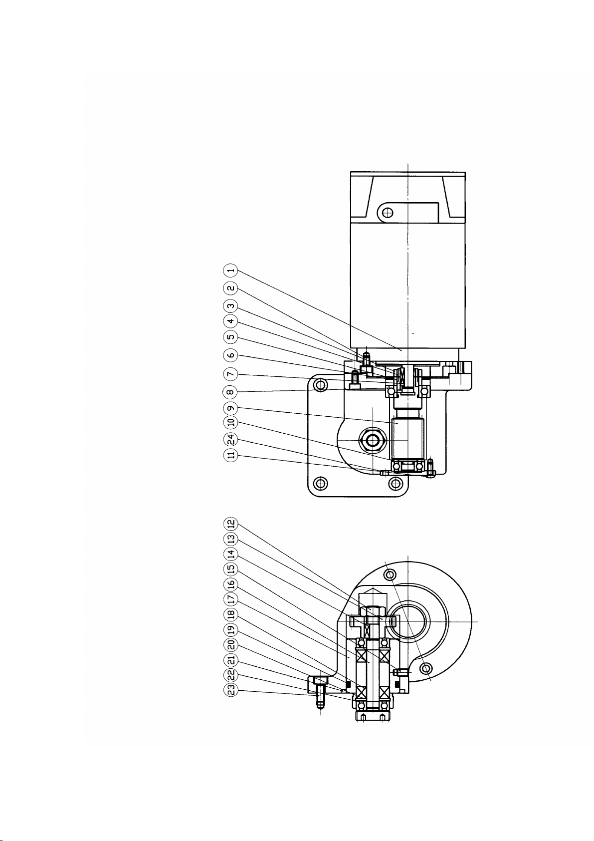
MOTOR DRIVE SYSTEM ASSEMBLY
KEY PART NUMBER DESCRIPTION QUANTITY
OOO1 GCT 1102F SPINDLE PULLEY 1
OOO2 11M1650 SPINDLE PULLEY BELT 1SET
OOO3 ESM05HP SPINDLE MOTOR 1
OOO4 SS 08012 SET SCREW 3
OOO5 GCT 31230 MOT OR PULLEY 1
OOO6 GCT 31280 SCREW 2
OOO7 HN 10 NUT 2
OOO8 GCT 31090 ROD 2
OOO9 GCT 31100 RUBBER BUSHING 2
OO1O GCT 31300 SUPPORT BASE 1
OO11 HN 10 NUT 4
OO12 HHS 10030 SCREW 4
OO13 GCT 31060 UPPER SOLID BLOCK 1
OO14 GCT 31040 LOWER SOLID BLOCK 1
OO15 HHS 08025 SCREW 2
OO16 GCT 31050 SCREW 1
OO17 HN 08F NUT 2
OO18 GCT 31310 RUBBER BUSHING 2
OO19 WS 08 WASHER 2
OO20 HHS 10040 SCREW 4
OO21 GCT 31340 MOTOR MOUNT BLOCK 1
60
Page 91

61
Page 92

PADESTAL ASSEMBLY NEW STYLE
KEY PART NUMBER DESCRIPTION QUANTITY
OOO1 GCT 31160 COLET HOLDER PLAT E 1
OOO2 GCT 31190 PULL ROD 1
OOO3 RHS 06015 SCREW 3
OOO4 GCT 31200 BUSHING 1
OOO5 GCT 31400 NAMEPLATE 1
OOO6 MP 02 NAMEPLATE PIN 1
OOO7 GCT 31480 RIGHT SIDE DOOR 4
OOO8 GCT 31220 TOOLING COLLECT IO N PLATE 1
OOO9 GCT 21010 BED BODY 1
OO1O GCT 31010 PEDESTAS 1
OO11 GCT 31020 OIL PAN 1
OO12 GCT 31490 LEFT SIDE DOOR 1
OO13 GCT 31440 CORD PRO 2
OO14 GCT 21210 CONTROL LEVER 1
OO15 GCT 21050 HI-LOW CONTROL LEVER 1
OO16 GCT 31500 MARK PLATE 1
OO17 MP 02 MARK PLATE PINS 4
OO18 GCT 31460 PULL ROD 1
OO19 GCT 31120 PANEL 1
OO20 GCT 31130 P ANEL COVER 1
OO21 VB 268935 DRIVE BELTS 2
OO22 GCT 36080 PULLEY 1
OO23 HHS 010025 HEX.SCREEW 2
OO24 GCT 31030 A DJUSTING SCREW 6
OO25 GCT 3103 0A PAD 6
OO26 GCT 31050 S UPPORT STUD 1
OO27 HN 08BF HEX NUT 2
OO28 HHS 08025 HEX HEAD SCREW 2
OO29 GCT 31060 UPPER SUPPORT PLATE 1
OO30 GCT 31040 LOWER SUPPORT PLATE 1
OO31 GCT 31240 PULLEY 1
OO32 EAM 41201 MOTOR 1
OO33 HHS 12035 HEX HEAD SCREW 4
OO33A HN 012 HEX NUT 4
OO34 GCT 31300 MOTOR PLATE 1
OO35 HN 10BF HEX NUT 2
OO36 GCT 31280 HINGE EYE BOLT 2
OO37 GCT 31090 ROD 2
OO38 GCT 31080 REAR COVER 1
OO39 RHS 06015 SCREW 4
62
Page 93

63
Page 94

CONTROL PLATE ASSEMBLY
KEY PART NUMBER DESCRIPTION QUANTITY
OOO1 GCT-37010 CONTROL BOX 1
OOO2 GCT 37020 CONTROL PLATE 1
OOO3 EP 8025 POWER SWITCH 1
OOO4 HRS05080 SCREW 1
OOO5 GCT 37050 SUPPORT ROD 1
OOO6 ETS 025 TOGGLE SWITCH 1
OOO7 ECN 012 NUT 1
OOO8 ECC12 CONDUIT 1
OOO9 ELD-24V LED 1
OO1O EES 025 EMERGENCE SWITCH 1
OO11 EB 202 ADJ. SWITCH 1
OO12 EB 202BR KNOB BRAKET 1
OO13 EB 202KB MICRO KNOB 1
64
Page 95

65
Page 96
66
Page 97

67
68
Page 98

Page 99

69
Page 100

 Loading...