

Shark SSD-603567E,SSD-603567E/G Operator's Manual
SSD
98011940-1
L
I
S
T
E
D
®
OPERATOR’S MANUAL
SSD-603567E 1.110-586.0
SSD-603567E/G
To locate your local Shark Commercial Pressure Washer Dealer nearest you,
MODEL # ORDER #
1.110-587.0
visit www.sharkpw.com
9.801-194.0


Introduction & Important Safety Information 4-6
Component Identification 7
Assembly Instruction 8
Operating Instructions 9
Detergents & Cleaning Tips 10
Shut Down & Clean-Up 11
Storage 11
Maintenance 12-14
Troubleshooting 15-18
Preventative Maintenance & Oil Change Chart 19
Exploded View 20-21
Exploded View, Parts List 22-24
Hose and Spray Gun Assembly & Parts List 25
Platform, Isolator, Exploded View & Parts List 26-27
CONTENTS
Pump Assemblies, Exploded View 28
Pump Assemblies, Parts List 29
Control Box, Exploded View & Parts List 30
Float Tank Assembly, Exploded View & Parts List 31
Specifications 32
VRT 3 Unloader Exploded View & Parts List 33
KT.1 Series Pump Exploded View & Parts List 34-35
Clear Flame Burner "S" Replacement & Parts List 36-37
Clear Flame Burner "M/L" Replacement & Parts List 38-39
Warranty
Model Number ______________________________
Serial Number ______________________________
Date of Purchase ____________________________
The model and serial numbers will be found on a decal attached
to the pressure washer. You should record both serial number and
date of purchase and keep in a safe place for future reference.
3
SSD • 9.801-194.0 • Rev. 12/13
INTRODUCTION & IMPORTANT SAFETY INFORMATION
MANUAL THOROUGHLY
WARNING
WARNING
WARNING
WARNING
WARNING
Thank you for purchasing a Shark Pressure Washer. We
reserve the right to make changes at any time without
incurring any obligation.
Owner/User Responsibility:
The owner and/or user must have an understanding of
the manufacturer’s operating instructions and warnings
before using this pressure washer. Warning information
PRESSURE WASHER
should be emphasized and understood. If the operator
is not fluent in English, the manufacturer’s instructions
and warnings shall be read to and discussed with
the operator in the operator’s native language by the
purchaser/owner, making sure that the operator comprehends its contents.
Owner and/or user must study and maintain for future
reference the manufacturers’ instructions.
OPERATOR’S MANUAL
The operator must know how to stop the machine
quickly and understand the operation of all controls.
Never permit anyone to operate the engine without
proper instructions.
SAVE THESE INSTRUCTIONS
This manual should be considered a permanent
part of the machine and should remain with it if
machine is resold.
When ordering parts, please specify model and serial number. Use only identical replacement parts.
This machine is to be used only by trained
operators.
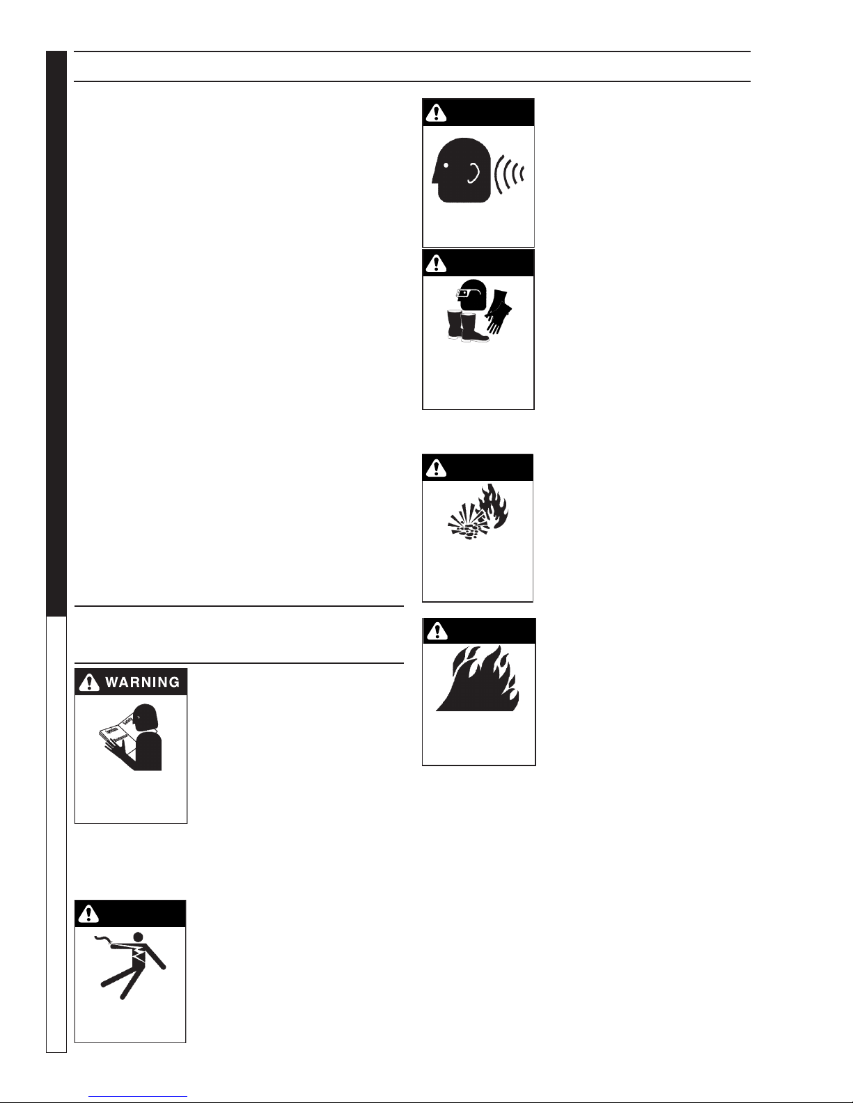
WARNING: This machine exceeds
85 db appropriate ear protection
must be worn.
EAR PROTECTION
MUST BE WORN
WARNING: High pressure spray
can cause paint chips or other
particles to become airborne
and fly at high speeds. To avoid
personal injury, eye, hand and
USE PROTECTIVE
EYE WEAR
AND CLOTHING
WHEN OPERATING
THIS EQUIPMENT.
foot safety devices must be
worn.
5. Eye, hand, and foot protection
must be worn when using this
equipment.
6. Keep operating area clear of all persons.
WARNING: Flammable liquids
can create fumes which can ignite, causing property damage
or severe injury.
RISK OF EXPLOSION:
OPERATE ONLY
WHERE OPEN FLAME
OR TORCH IS
PERMITTED
WARNING: Risk of explosion —
Operate only where open flame
or torch is permitted.
IMPORTANT SAFETY
INFORMATION
WARNING: To reduce the risk of
injury, read operating instructions carefully before using.
1. Read the owner's manual
thoroughly. Failure to follow
instructions could cause mal-
READ OPERATOR’S
PRIOR TO USE.
2. Know how to stop the machine and bleed pressure
quickly. Be thoroughly familiar with the controls.
3. Stay alert — watch what you are doing.
KEEP WATER
SPRAY AWAY FROM
ELECTRICAL WIRING.
4
function of the machine and
result in death, serious bodily
injury and/or property damage.
WARNING: Keep wand, hose, and
water spray away from electric
wiring or fatal electric shock may
result.
4. All installations must comply with
local codes. Contact your electrician, plumber, utility company or
the selling distributor for specific
details.
RISK OF FIRE.
DO NOT ADD FUEL
WHEN OPERATING
MACHINE.
Spray flammable liquids.
7. Allow engine to cool for 1-2 minutes before refueling. If any fuel is spilled, make sure the area is dry
before testing the spark plug or starting the engine.
(Fire and/or explosion may occur if this is not done.)
Gasoline engines on mobile or portable equipment
shall be refueled:
a. outdoors;
b. with the engine on the equipment stopped;
c. with no source of ignition within 10 feet of
the dispensing point; and
d. with an allowance made for expansion of the
fuel should the equipment be exposed to a
higher ambient temperature.
SSD • 9.801-194.0 • Rev. 12/13
WARNING: Risk of fire — Do not
add fuel when the product is
operating or still hot.
WARNING: Do not use gasoline
crankcase draining or oil containing gasoline, solvents or
alcohol. Doing so will result in
fire and/or explosion.
WARNING: Risk of fire — Do not
WARNING
WARNING
WARNING
WARNING
IMPORTANT SAFETY INFORMATION
WARNING
WARNING
PRESSURE WASHER
In an overfilling situation, additional precautions are
necessary to ensure that the situation is handled
in a safe manner.
WARNING: Risk of injury. Disconnect battery
ground terminal before servicing.
8. When in use , do not place machine near flammable
objects as the engine is hot.
9. Oil burning appliances shall be installed only in
locations where combustible dusts and flammable
gases or vapors are not present. Do not store or
use gasoline near this machine.
10. Use No. 1 or No. 2 heating oil (ASTM D306) only.
NEVER use gasoline in your fuel oil tank. Gasoline
is more combustible than fuel oil and could result
in a serious explosion. NEVER use crankcase or
waste oil in your burner. Fuel unit malfunction could
result from contamination.
11. Do not confuse gasoline and fuel oil tanks. Keep
proper fuel in proper tank.
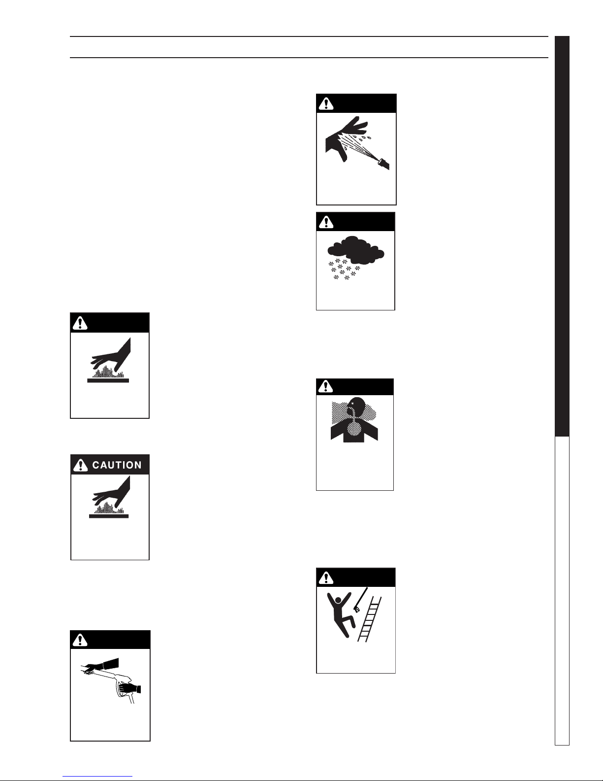
WARNING: Risk of injury. Hot
surfaces can cause burns. Use
only designated gripping areas
of spray gun and wand. Do not
place hands or feet on non-insulated areas of the pressure
RISK OF INJURY.
HOT SURFACES
CAN CAUSE BURNS
washer.
12. Transport/repair with fuel tank EMPTY or with fuel
shut-off valve OFF.
CAUTION: Hot discharge fluid.
Do not touch or direct discharge
stream at persons.
WARNING: This machine produces hot water and must have
HOT DISCHARGE
FLUID: DO NOT
TOUCH OR DIRECT
DISCHARGE STREAM
AT PERSONS.
insulated components attached
to protect the operator.
13. To reduce the risk of injury, close supervision is
necessary when a machine is used near children.
Do not allow children to operate the pressure
washer. This machine must be attended during
operation.
WARNING: Grip cleaning wand
securely with both hands before
starting. Failure to do this could
result in injury from a whipping
wand.
14. Never make adjustments on
TRIGGER GUN KICKS
BACK - HOLD WITH
BOTH HANDS
machine while in operation.
SSD • 9.801-194.0 • Rev. 12/13
15. Be certain all quick coupler fittings are secured
before using pressure washer.
WARNING: High pressure devel-
oped by these machines will
cause personal injury or equipment damage. Keep clear of
nozzle. Use caution when operating. Do not direct discharge
RISK OF INJECTION
OR SEVERE INJURY
TO PERSONS. KEEP
CLEAR OF NOZZLE.
stream at people, or severe injury or death will result.
WARNING: Protect machine from
freezing.
16. To keep machine in best
operating conditions, it is
important you protect machine
from freezing. Failure to protect
PROTECT FROM
FREEZING
machine from freezing
could cause malfunction of the
machine and result in death,
serious bodily injury, and/or property damage. Follow storage instructions specified in this manual.
17. Inlet water must be clean fresh water and no hotter
then 90°F.
WARNING: Risk of asphyxiation.
Use this product only in a well
ventilated area.
18. Avoid installing machines in
small areas or near exhaust
RISK OF
ASPHYXIATION: USE
THIS PRODUCT ONLY
IN A WELL
VENTILATED AREA.
fans. Adequate oxygen is
needed for combustion or
dangerous carbon monoxide
will result.
19. Manufacturer will not be liable for any changes
made to our standard machines or any components
not purchased from us.
20. The best insurance against an accident is precaution and knowledge of the machine.
WARNING: Be extremely careful
when using a ladder, scaffolding
or any other relatively unstable
location. The cleaning area
should have adequate slopes
and drainage to reduce the pos-
RISK OF INJURY
FROM FALLS WHEN
USING LADDER.
sibility of a fall due to slippery
surfaces.
21. Do not allow acids, caustic or abrasive fluids to pass
through the pump.
22. Never run pump dry or leave spray gun closed
longer than 1-2 minutes.
OPERATOR’S MANUAL
5

IMPORTANT SAFETY INFORMATION
23. Machines with shut-off spray gun should not be
operated with the spray gun in the off position for
extensive periods of time as this may cause damage to the pump.
24. Protect discharge hose from vehicle traffic and
sharp objects. Inspect condition of high pressure
hose before using or bodily injury may result.
PRESSURE WASHER
25. Before disconnecting discharge hose from water
outlet, turn burner off and open spray gun to allow water to cool below 100° before stopping the
machine. Then open the spray gun to relieve pressure. Failure to properly cool down or maintain the
heating coil may result in a steam explosion.
26. Do not overreach or stand on unstable support.
Keep good footing and balance at all times.
OPERATOR’S MANUAL
27. Do not operate this machine when fatigued or under
the influence of alcohol, prescription medications,
or drugs.
28. In oil burning models, use only kerosene, No. 1
home heating fuel, or diesel. If diesel is used, add
a soot remover to every tankful.
Follow the maintenance instructions
specified in the manual.
6
SSD • 9.801-194.0 • Rev. 12/13
98011940-2
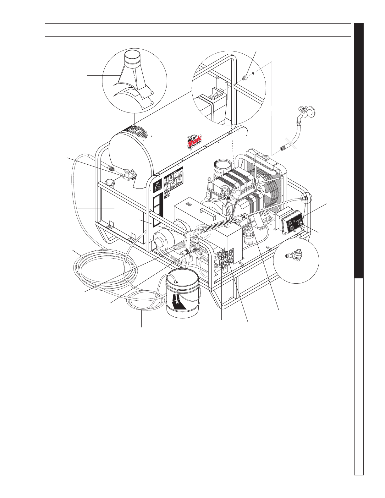
Flue Adapter
Optional 7-10049
Insulation Gasket
Optional 7-01471
NOTE: Burner air adjustment
must be tested after installation.
Rupture
Disk
Detergent
Metering
Valve
Diesel
Fuel Tank
PRESSURE WASHER
COMPONENT IDENTIFICATION
Inlet Connection
Water
Supply Hose
(not included)
OPERATOR’S MANUAL
Burner
Switch
Spray
Gun
High
Pressure
Hose
Unloader
Valve
Trigger/Safety
Latch
Pick-up Hose
Pump — Develops high pressure by pumping water
volume through nozzle.
Spray Gun — Controls the application of water and
detergent onto cleaning surface with trigger device.
Includes safety latch.
Detergent Metering Valve — Controls detergent
mixture.
Wand — Must be connected to the spray gun.
Rupture Disk — Will burst when extreme pressure
limits are reached.
Pressure Switch — Activates fuel solenoid to turn off
burner when trigger on spray gun is released.
Detergent
Pump
Detergent Bucket
(not included)
Unloader Valve — Safety control which releases
pressure when spray gun trigger is released.
High Pressure Hose — Connect one end to water
pump discharge nipple and the other end to spray
gun.
Pressure Nozzle — Inserted into wand quick coupler
to develop pressure
Adjustable Thermostat — Prevents water temperature from exceeding high temperatures. Is not used to
maintain constant temperature setting.
SSD • 9.801-194.0 • Rev. 12/13
Adjustable
Thermostat
Pressure
Nozzle
Wand
Pressure
Switch
7
98011940-10
98011940-15
98011940-13
98011940-12
98011940-11
ASSEMBLY INSTRUCTIONS
98011940-14
Spray
Gun
Safety
Latch
High
PRESSURE WASHER
Pressure
Hose
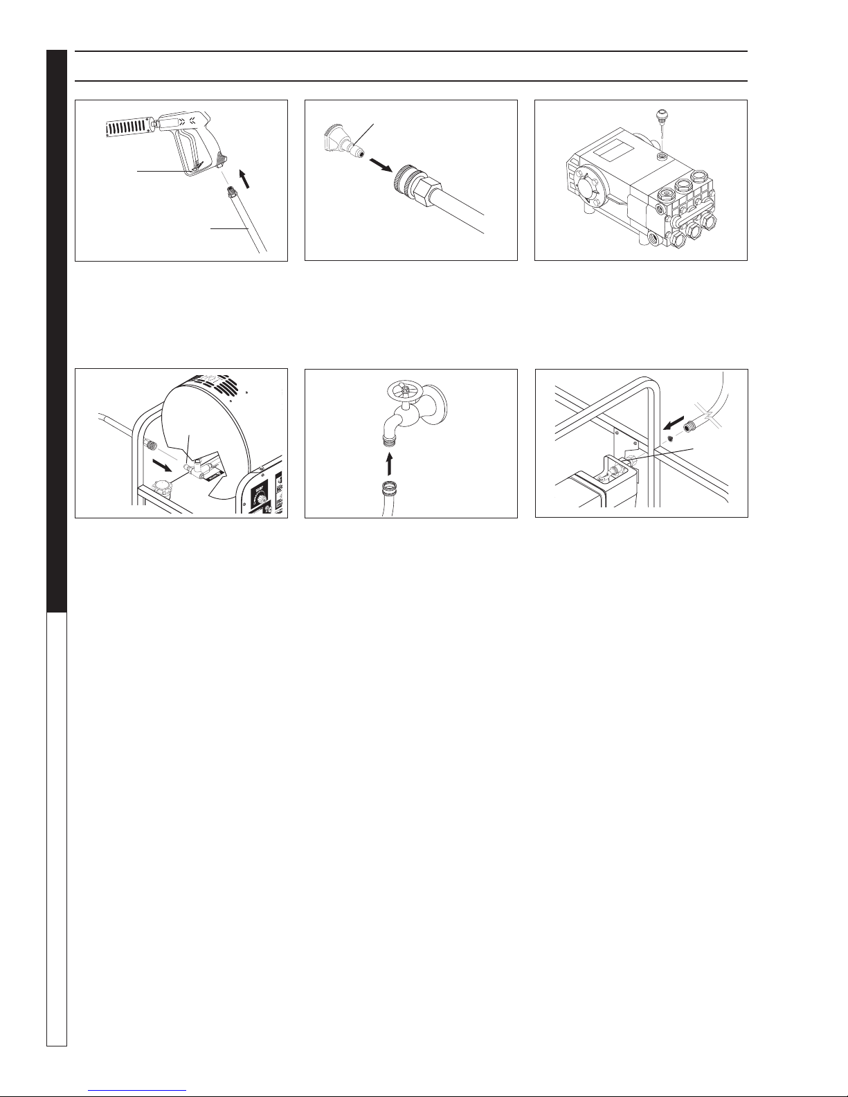
STEP 1: Attach the high pressure
hose to the spray gun using teflon
tape on hose threads.
OPERATOR’S MANUAL
Pump
Discharge
Fitting
Pressure
Nozzle
Wand
STEP 2: Pull the spring-loaded
collar of the wand coupler back to insert your choice of pressure nozzle.
Dipstick
STEP 3: Remove shipping cap and
install oil dipstick. Check pump oil
level by using dipstick or observe
oil level in oil window (if equipped).
Use 30 wt. non detergent oil.
Garden
Hose
Water
Inlet
STEP 4: Connect the high pressure
hose to the pump discharge fitting.
Push coupler collar forward until
secure.
STEP 5: Connect garden hose to
cold water source and turn water on
completely. Never use hot water.
STEP 6: Connect the garden hose
to pump water inlet. Inspect inlets.
CAUTION: Do not run the pump
without water or pump damage
will result.
8
SSD • 9.801-194.0 • Rev. 12/13
98011940-17
OPERATING INSTRUCTIONS
98011940-16
98011940-19
98011940-21
PRESSURE WASHER
Oil Dipstick
Oil Cap Filter
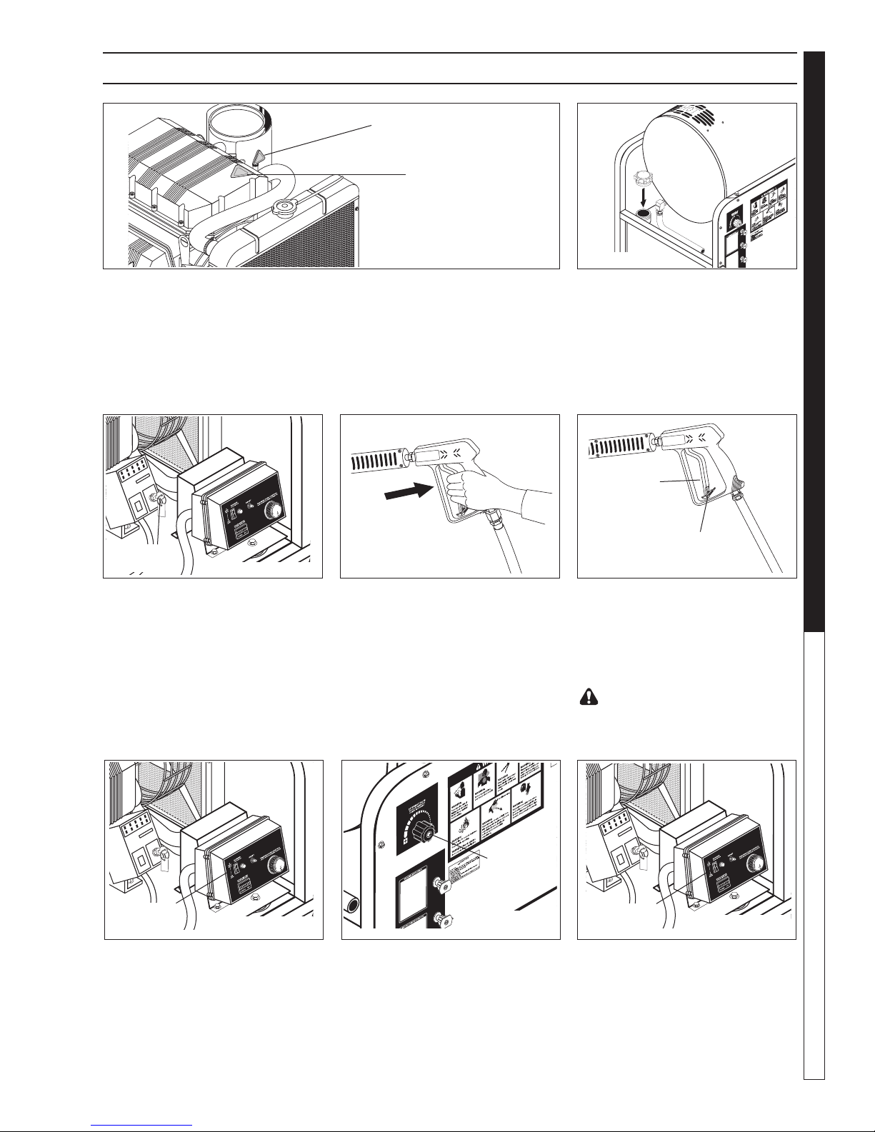
STEP 1: Read operator's manual before operating machine. Check engine
oil level. Oil level should be level with the bottom of the oil filler neck. (Refer
to the engine’s operating manual included with machine.) We recommend
that the oil be changed after the first 50 hours of use, then once every
250 hours. NOTE: Improper oil levels will cause low oil sensor to shut off
engine. IMPORTANT! Do not run engine with high or low oil levels
as this will cause engine damage.
Fuel
Tank
OPERATOR’S MANUAL
STEP 2: Fill engine fuel tank with
No. 2 diesel fuel. Check engine and
pump oil levels. Check engine radiator fluid level. Install battery and
connect red cable to the + terminal
and black to the - terminal.
Trigger
Key
Switch
98011940-18
STEP 3: Read engine manual. The
keyed ignition is located on the engine control panel. Turn key to first
position. The glow plug light will illuminate. When the light goes out, turn
key to start (second) position. Do not
hold key in start position longer than
five (5) seconds or starter motor will
be damaged.
Burner
Switch
98011940-18
STEP 4: Before installing pressure nozzle, trigger spray gun to
eliminate trapped pressure. Then
run machine allowing water to flush
through the system until clear.
Detergent
Valve
Safety
98011940-20
Latch
STEP 5: With spray gun and wand
pointed away from you or anybody
else, insert pressure nozzle into
quick coupler on end of wand.
Press trigger on spray gun to obtain
pressurized cold water spray.
WARNING! Never replace nozzles without engaging the safety
latch on the spray gun trigger.
Burner
Switch
98011940-18
STEP 6: For hot water, turn the
burner switch to ON when a steady
stream of water flows out of the
spray gun. Burner will light automatically.
NOTE: Do not start machine with
burner switch on.
STEP 7: To apply detergent, place
detergent pick-up tube into a container of detergent and turn the
detergent valve counterclockwise.
SSD • 9.801-194.0 • Rev. 12/13
STEP 8: To stop, reverse steps
and set all controls to their original
settings.
Turn burner switch OFF and open
trigger on spray gun, allowing water
to cool.
9
WARNING
98011940-23
98011940-19
DETERGENTS & GENERAL CLEANING TECHNIQUES
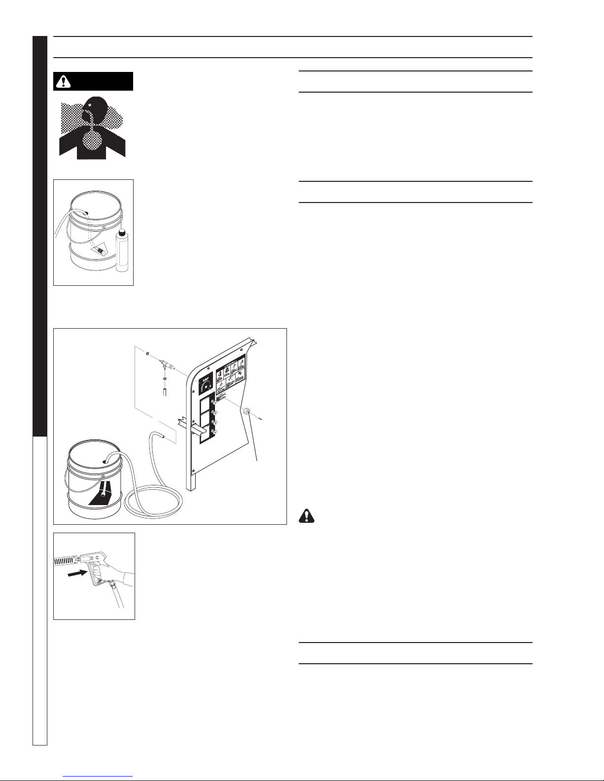
WARNING: Some detergents
may be harmful if inhaled or ingested, causing severe nausea,
fainting or poisoning. The harmful elements may cause property
damage or severe injury.
PRESSURE WASHER
STEP 1: Use detergent designed
specifically for pressure washers.
Household detergents could damage the pump. Prepare detergent
solution as required by the manufacturer. Fill a container with pressure washer detergent. Place the
OPERATOR’S MANUAL
STEP 2: Open detergent valve to desired mixture
ratio.
filter end of detergent suction tube
into the detergent container.
THERMAL PUMP PROTECTION
If you run the engine on your pressure washer for 3-5
minutes without pressing the trigger on the spray gun,
circulating water in the pump can reach high temperatures. When the water reaches this temperature,
the pump protector engages and cools the pump by
discharging the warm water onto the ground. This
thermal device prevents internal damage to the pump.
CLEANING TIPS
Pre-rinse cleaning surface with fresh water. Place
detergent suction tube directly into cleaning solution
and apply to surface (for best results, limit your work
area to sections approximately 6 feet square and always
apply detergent from bottom to top). Allow detergent
to remain on surface 1-3 minutes. Do not allow detergent to dry on surface. If surface appears to be drying,
simply wet down surface with fresh water. If needed,
use brush to remove stubborn dirt. Rinse from top to
bottom in an even sweeping motion keeping the spray
nozzle approximately 1 foot from cleaning surface. Use
overlapping strokes as you clean and rinse any surface.
For best surface cleaning action spray at a slight angle.
Detergent
Valve
STEP 3: With the engine running,
pull trigger to operate machine.
Liquid detergent is drawn into the
machine and mixed with water.
Apply detergent to work area.
Do not allow detergent to dry on
surface.
IMPORTANT: You must flush
the detergent line after each use by placing the
suction tube into a bucket of clean water, then run the
pressure washer for 1-2 minutes.
Recommendations:
• Before cleaning any surface, an inconspicuous
area should be cleaned to test spray pattern and
distance for maximum cleaning results.
• Ifpaintedsurfacesarepeelingorchipping,use
extreme caution as pressure washer may remove
the loose paint from the surface.
• Keepthespraynozzleasafedistancefromthe
surface you plan to clean. High pressure wash a
small area, then check the surface for damage.
If no damage is found, continue to pressure
washing.
CAUTION - Never use:
• Bleach, chlorine products and other corrosive
chemicals
• Liquids containing solvents (i.e., paint thinner,
gasoline, oils
• Tri-sodiumphosphateproducts
• Ammoniaproducts
• Acid-basedproducts
These chemicals will harm the machine and will damage the surface being cleaned.
RINSING
It will take a few seconds for the detergent to clear.
Apply safety latch to spray gun. Open detergent valve.
Select and install the desired high pressure nozzle.
NOTE: You can also stop detergent from flowing by
simply removing detergent siphon tube from bottle.
10
SSD • 9.801-194.0 • Rev. 12/13
98011940-18
98011940-20
98011940-24
SHUTTING DOWN AND CLEAN-UP
98011940-25
98011940-19
98011940-26
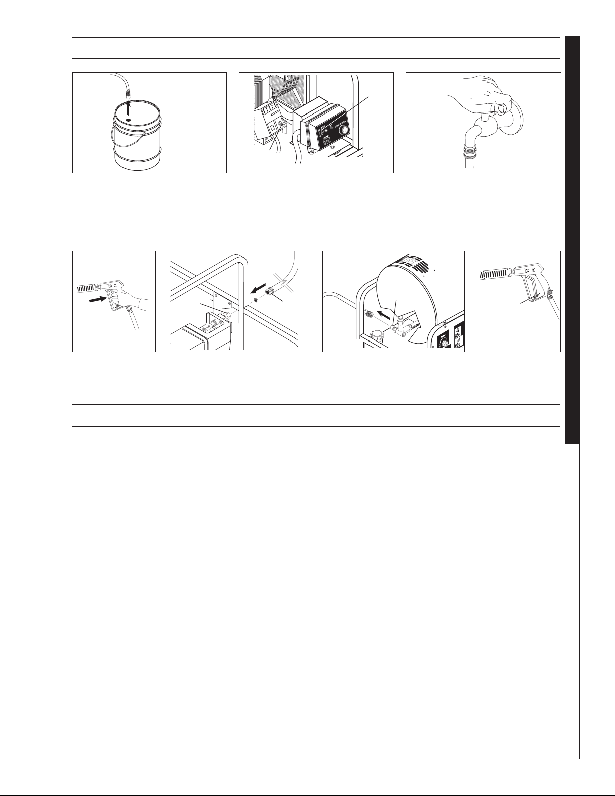
STEP 1: Remove detergent suction
tube from container and insert into
one gallon of fresh water. Open
detergent mixing valve. Pull trigger
on spray gun and siphon water for
one minute.
Water
Inlet
Burner
Switch
On-Off
Key Switch
STEP 2: Turn burner switch off and
continue spraying, allowing water to
cool below 100°F.
To stop engine, turn key to off
position.
Pressure
Outlet
Garden
Inlet
STEP 3: Turn off water supply.
High
Safety
Latch
PRESSURE WASHER
OPERATOR’S MANUAL
STEP 4: Press trigger to release water pressure.
STEP 5: Disconnect the garden
hose from the water inlet on the
machine.
Measures should be taken to protect your FOCS series
engine if the engine is not operated for a period of 30
days or more. Proper storage will protect the engine
from corrosion and prevent costly repairs due to storage
induced problems.
Storage - 1 to 6 months
1. Start and idle the engine at a no-load condition for
15 minutes.
2. Stop the engine, allow the engine to cool enough
to safely drain the oil as shown Re-install the oil
drain plug, then fill the crankcase with MIL-L-644P9 protectant oil. Fill the fuel tank with a high grade
fuel preservative (add mix) such as STA-BIL per the
manufacturer recommendations.
3. Start and operate the engine at 3/4 speed for 5-10
minutes.
4. Stop the engine, allow to cool enough to safely
drain the engine oil as shown. Re-install the oil
drain plug.
5. Refill the engine with standard recommended lubricating oil.
6. Drain the fuel tank. Remove the fuel filter. Install a
new fuel filter.
7. Carefully clean all debris from the radiator fins.
98011940-15
STEP 6: Disconnect the high
pressure hose from high
pressure outlet. Protect from
freezing.
STORAGE
8. Remove the intake manifold. Rotate the engine
until the intake valve opens at each cylinder. Using
suitable means, pour approximately 1 tsp. of engine
oil into each cylinder. Rotate the engine several
revolutions. Spray the inside of the intake manifold
with SAE 10 W oil. Replace the intake manifold
using a new gasket.
9. Spray the inside of the exhaust manifold with SAE
10W oil.
10. Cover all openings with tape and apply grease to
any and all unpainted surfaces.
11. Loosen the fan belt before wrapping the engine in
plastic film and storing in a dry place away from
high voltage sources and off the ground.
Storage - In excess of 6 months
Perform the storage preparation procedures approximately as detailed, except with the following changes.
1. Replace the oil in step 2 above with MIL-L-21260,
grade 2, SAE 30W rustproof oil.
2. Delete steps 5 and 11 above.
3. Coat any and all unpainted surfaces with MIL-C
16173D, grade 3 anti-rust grease.
4. Replace anti-freeze every 2 years.
SSD • 9.801-194.0 • Rev. 12/13
STEP 7: Engage
the spray gun
safety lock.
11

MAINTENANCE
PREVENTATIVE MAINTENANCE
1. Check to see that water pump is properly
lubricated.
2. Follow winterizing instructions to prevent freeze
damage to pump and coils.
3. Always neutralize and flush detergent from system
after use.
PRESSURE WASHER
4. If water is known to have high mineral content, use
a water softener in your water system, or de-scale
as needed.
5. Do not allow acidic, caustic or abrasive fluids to be
pumped through system.
6. Always use high grade quality cleaning products.
7. Never run pump dry for extended periods of time.
OPERATOR’S MANUAL
8. Use clean No. 2 diesel fuel. Clean or replace fuel
filter every 250 hours of operation. Avoid water
contaminated fuel as it will damage the fuel pump.
9. If machine is operated with smoky or eye burning
exhaust, coils will soot up. Adjust air bands and fuel
pressure for proper emission.
10. Never allow water to be sprayed on or near
the engine or burner assembly or any electrical
component.
11. Periodically delime coils as per instructions.
12. Check to see that engine is properly lubricated. Use
SAE 10W40 grade oil.
It is advisable, periodically, to visually inspect the
burner. Check air inlet to make sure it is not clogged
or blocked. Wipe off any oil spills and keep equipment
clean and dry.
The flow of combustion and ventilating air to the burner
must not be blocked or obstructed in any manner.
The area around the washer should be kept clean
and free of combustible materials, gasoline and other
flammable vapors and liquids.
Winterizing Procedure:
Damage due to freezing is not covered by warranty.
Adhere to the following cold weather procedures whenever the washer must be stored or operated outdoors
under freezing conditions.
During winter months, when temperatures drop below
32°F, protecting your machine against freezing is necessary. Store the machine in a heated room. If this is not
possible then mix a 50/50 solution of anti-freeze and
water in the float tank. Turn the engine on to siphon the
anti-freeze mixture through the machine. If compressed
air is available, an air fitting can be screwed into the
float tank by removing the float tank strainer and fitting.
Then inject the compressed air. Water will be blown
out of the machine when the trigger on the spray gun
is opened.
High Limit Hot Water Thermostat:
For safety, each machine is equipped with a temperature sensitive high limit control switch. In the event that
the water should exceed its operating temperature,
the high limit control will turn the burner off until the
water cools, then it will automatically reset itself. The
thermostat sensor is located on the discharge side of
the heating coil. The thermostat control dial is located
on the control panel.
Pumps:
Use only SAE 10/40 weight non-detergent oil. Change
oil after first 50 hours of use. Thereafter, change oil
every three months or at 500 hour intervals. Oil level
should be checked through use of dipstick found on top
of pump, or the red dot visible through the oil gauge
window. Oil should be maintained at that level.
MAINTENANCE AND SERVICE
Unloader Valves:
Unloader valves are preset and tested at the factory
before shipping. Occasional adjustment of the unloader
may be necessary to maintain correct pressure.
Adjusting Unloader Valves:
Tampering with the factory setting may cause
personal injury and/or property damage and will void
the manufacturer's warranty.
12
SSD • 9.801-194.0 • Rev. 12/13
MAINTENANCE AND SERVICE
98011930-28
PRESSURE WASHER
Deliming Coils:
Periodic flushing of coils or optional float tank is
recommended.
Step 1 Fill a container with 4 gallons of water, then .
add 1 lb. of deliming powder. Mix thoroughly.
Pour mixture into float tank.
Step 2 Remove wand assembly from spray gun and
put spray gun into float tank. Secure the trig ger on the spray gun into the open position.
Step 3 Turn engine on, allowing solution to be
pumped through coils back into the float tank.
The solution should be allowed to circulate 2- 4
hours or until the color changes.
Step 4 After circulating solution, flush the entire
system with fresh water. Clean out float tank
and then reinstall wand assembly to spray gun.
Removal of Soot from Heating Coil:
In the heating process, fuel residue in the form of soot
deposits may develop between the heating coil pipe,
and block air flow which will affect burner combustion.
When soot has been detected on visual observation,
the soot on the coil must be washed off after following
the coil removal steps (See Coil Removal section).
Fuel:
Use clean fuel oil that is not contaminated with water
and debris. Replace fuel filter and drain tank every 100
hours of operation.
Use No.1 or No 2 Heating Oil (ASTM D306) only.
NEVER use gasoline in your burner fuel tank. Gasoline
is more combustible than fuel oil and could result in a
serious explosion. NEVER use crankcase or waste oil
in your burner. Fuel unit malfunction could result from
contamination.
Fuel Control System:
This machine utilizes a fuel solenoid valve located on
the fuel pump to control the flow of fuel to the combustion chamber. The solenoid, which is normally closed,
is activated by a flow switch when water flows through
it. When the operator releases the trigger on the spray
gun, the flow of water through the flow switch stops,
turning off the electrical current to the fuel solenoid.
The solenoid then closes, shutting off the supply of
fuel to the combustion chamber. Controlling the flow
of fuel in this way gives an instantaneous burn-or-noburn situation, thereby eliminating high and low water
temperatures and the combustion smoke normally
associated with machines incorporating a spray gun.
Periodic inspection, to insure that the fuel solenoid
valve functions properly, is recommended. This can
be done by operating the machine and checking to
see that the burner is not firing when the spray gun is
in the OFF position.
Fuel Pressure Adjustment:
To control water temperature, adjust fuel pressure
by turning the regulating pressure adjusting screw
clockwise to increase, counterclockwise to decrease.
NOTE: When changing fuel pump, a bypass plug must
be installed in return port or fuel pump will not prime.
Burner Nozzle:
Keep the tip free of surface deposits by wiping it with
a clean, solvent saturated cloth, being careful not to
plug or enlarge the nozzle. For maximum efficiency,
replace the nozzle each season.
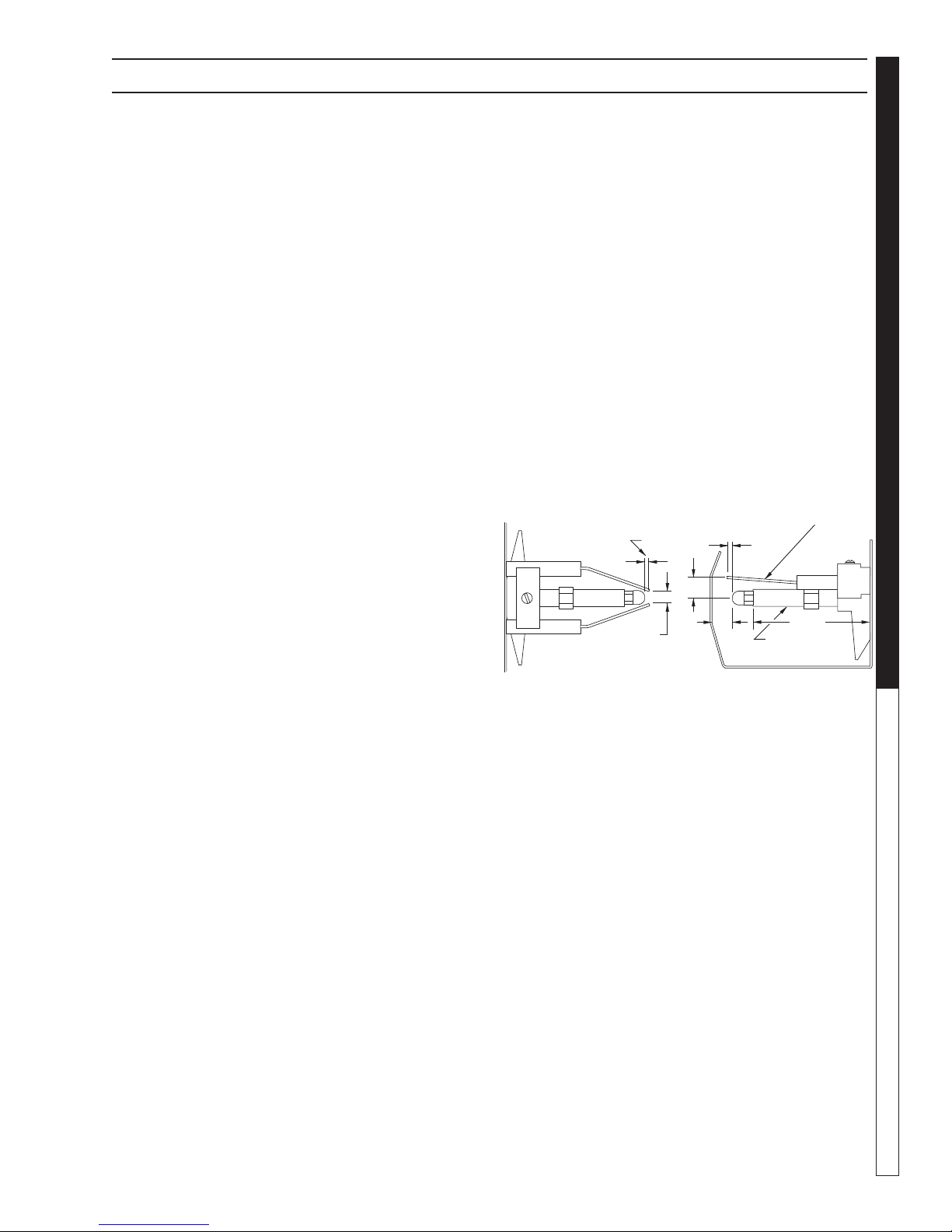
Electrode Setting:
Electrodes
Gap
1/8"
3/8"
3/16"
Top View Side View
Periodically Check Wiring Connections. If Necessary
To Adjust Electrodes, Use Diagram.
1/2"
1/8"
2-7/8"
Nozzle
Adapter
Beckett Burner Air Adjustment:
The oil burner on this machine is preset for operation
at altitudes below 1000 feet. If operated at higher
altitudes, it may be necessary to adjust the air band
setting. Adjust air band for a #1 or #2 smoke spot
on the Bacharach scale. If a smoky or eye-burning
exhaust is being emitted from the stack, two things
should be checked. First, check the fuel to be certain
that kerosene or No.1 home heating fuel is being used.
Next, check the air adjustment on the burner. An oily,
smoky fire indicates a lack of air and the air band
should be moved to allow the air to flow through the
burner. Sharp eye-burning fumes indicate too much
air flowing through the combustion chamber. The air
band should be readjusted to allow less air to flow
through the burner.
OPERATOR’S MANUAL
13
SSD • 9.801-194.0 • Rev. 12/13
 Loading...